EP1577752A2 - Software development using visual interfaces - Google Patents
Software development using visual interfaces Download PDFInfo
- Publication number
- EP1577752A2 EP1577752A2 EP05002376A EP05002376A EP1577752A2 EP 1577752 A2 EP1577752 A2 EP 1577752A2 EP 05002376 A EP05002376 A EP 05002376A EP 05002376 A EP05002376 A EP 05002376A EP 1577752 A2 EP1577752 A2 EP 1577752A2
- Authority
- EP
- European Patent Office
- Prior art keywords
- user interface
- elements
- user
- action elements
- documentation
- Prior art date
- Legal status (The legal status is an assumption and is not a legal conclusion. Google has not performed a legal analysis and makes no representation as to the accuracy of the status listed.)
- Ceased
Links
Images


Classifications
-
- G—PHYSICS
- G06—COMPUTING; CALCULATING OR COUNTING
- G06F—ELECTRIC DIGITAL DATA PROCESSING
- G06F8/00—Arrangements for software engineering
- G06F8/30—Creation or generation of source code
- G06F8/34—Graphical or visual programming
-
- G—PHYSICS
- G06—COMPUTING; CALCULATING OR COUNTING
- G06F—ELECTRIC DIGITAL DATA PROCESSING
- G06F8/00—Arrangements for software engineering
- G06F8/10—Requirements analysis; Specification techniques
Definitions
- This invention relates to the field of software engineering, and more specifically to a method and apparatus to gather and review requirements, specifications, interfaces, documentation, and other elements of an information system over the various phases of the information system's life cycle.
- SDLC software development life cycle
- the invention resides in a method comprising: providing a user interface having action elements; and providing a mechanism for specification and review of the action elements using the user interface.
- a second embodiment teaches a software system comprising: a database schema to map visual action elements with corresponding behavioral implementation elements; and, a mechanism to display the visual action elements as part of a user interface, and to accept comments related to the visual action elements.
- Another embodiment teaches an apparatus with a computer-readable medium having information stored thereon, the information comprising: a user interface having action elements; a database schema having descriptive elements for the action elements; and, a user interaction tool to display the user interface and allow a user to interact with the descriptive elements.
- FIG. 1 shows modeling of nodes and events at different levels.
- FIG. 2 is a schema for gathering requirements and engineering enterprise software.
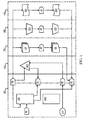
- FIG. 3 is a chart of levels used in schema 200 for engineering the enterprise software.
- FIG. 4 shows a preview-architecture of a prototype tool.
- FIG. 5 shows a user interface in the preview architecture of FIG. 4.
- FIG. 6 shows user interface review comments.
- FIG. 7 shows a tool to display an animation of a stimulus response sequence.
- FIG. 8 is a schematic block diagram of an exemplary information-processing system that can be used in conjunction with various embodiments of the present invention.
- Enterprise applications are systems that typically respond to either external stimulus or a system stimulus.
- various embodiments of the present invention model business systems using node/event pairs.
- the event depicts the stimulus
- the node depicts the response to the stimulus
- the response to the stimulus may lead to a new stimulus to the business system.
- the use of events and nodes to specify the behavior of the business systems at different levels ensures that there is coherence between the specifications at a process level, and that the coherence seamlessly percolates down to the system implementation.
- application and business architecture is defined in the following five elements: (A) the business functions performed in an organization, (B) the activities performed inside a business function in response to happenings within and from outside the system, (C) the user interfaces used as a set to complete each of activities to capture and retrieve information, (D) the tasks or actions performed to fill, persist and retrieve various elements on the user interfaces, and (E) the business rules that govern each of such tasks.
- Each of the five elements is represented by a data structure (in some embodiments these are, for example, five interrelated portions of a single larger data structure), into which data regarding requirements is entered.
- attributes for user interfaces such as whether to use buttons, radio dials, fields, etc.
- Attributes for activities may include whether the activity is system or user initiated.
- a user-initiated activity might appear as a menu item, but system initiated activity will not appear as a menu item.
- a function might be an external function, in which case it might be interfaced to another system for implementation of the function itself.
- the standard architectural elements of such an approach which correspond to the above five elements, then are (a) Business functions, (b) Business activities, (c) User interfaces or forms, (d) Tasks or actions performed on the user interface, and (e) Business rules.
- Various embodiments of the present invention model high-level specifications for business systems as node/event pairs, or "stimulus response" at different levels.
- Each of the events may have different attributes, including, but not limited to: Exit/Entry event; Start/End/Intermediate event; Information Exchange or Transfer of Control.
- FIG. 1 shows a diagram illustrating the modeling of nodes and events.
- process flow level 102 each node depicts a business function.
- the entry and exit events specify the triggers that the function needs to respond to and in turn trigger other functions.
- activity level 104 nodes are activities.
- the activities and their associated events are modeled as node/event pairs.
- the external events that are triggered in the process level are modeled as entry events in activity levels and these form the menu items.
- the interactions of different activities depict the workflow in the system.
- the nodes in the next level 106 are user interfaces and these form the basis for the visual interaction across and within functions.
- the transfers of control (TC) events depict the forward traversal of the user interface and the information exchange depicts the lookup screens traversals.
- Various node/event pairs may also be modeled at this level.
- the nodes at the next level 108 relate to user action, and the events across these depict the user navigation scheme within the user interface, and the nodes at the next level 110 are the top level business rules which depict the flow of methods. These high-level flow business rules set the context for specifying the detailed business rules.
- the events cutting across function are mapped as a collection of forward traversals across component boundaries and as the integration services calls across component boundaries and invocation of database methods across component boundaries. This way there is a strong correlation of the interactions at a higher level (coarse) and the interaction at a lower (detailed) level.
- This methodology for requirements specifications provides a well defined traceability at different stages of the software development life cycle, and, leakage across stages of the life cycle is reduced. Further, this methodology allows business users to specify requirements in a language that they are conversant with (e.g., functions and their interactions).
- Figure 2 is a schema 200 for gathering requirements and for creating and managing enterprise software from the gathered requirements.
- Schema 200 includes multiple levels of abstraction of requirements,
- the first level 202 is an application or business architecture level. This level is used to define the high level requirements in context relevant syntax.
- the levels are stored in a database schema form in one embodiment, such that lower levels, progressing toward actual coding are linked to high levels.
- a second level 204 is used to represent a technical or design architecture of the first level. It serves as an intermediate link between the first level and a third level 206 represents the actual building blocks and technology specific customization.
- the first level is a process expression level. It includes a plurality of elements or units, each of which stores various aspects of specifications derived from the requirements and software built to those specifications.
- schema level 202 includes business processes 211 that define the requirements at a level compatible with the thinking processes of business-requirements experts.
- business processes 211 are divided into a first five units including business functions 212, business activities 213, user interfaces 214, actions 215, and business rules 216.
- An example of a business process might be purchase order processing for a business.
- Business functions 212 would include purchase requisitioning, approval and purchase order dispatch.
- Business activities might include an acknowledgement, get best quote, release purchase order.
- User interfaces may be defined in terms of show all pending purchase orders for approval, an approval screen, and others. Actions may include things like fetch next purchase order for approval, link to next page, send acknowledgement, or send rejection.
- the first level 202 contains a textual description of the business or other process to be implemented by a computer system or otherwise electronically.
- the descriptions take the form of text that is very relevant to one who is designing the business process. In one sense, it is an abstract representation of the actual code that will be written, but in another sense, it separates the structure of the implementation from the expression of the process.
- Business processes 211 and their associated events 221 represent the operational flow across the organization for which the software is being developed.
- Events 221, in the form of entry and exit events to the constituent functions, activities, and interfaces are connectors that define flow of control or interfaces between other units.
- Business activities and their associated events represent the operational flow across a unit within the organization.
- User interfaces 214 and their associated events 221 represent the specified interface map for the systems and software being developed.
- Links 222 are formed from mapping of events 221 that represent interconnections, or from user interfaces 234, Integration services 223 are formed from mapping of events 221, business rules 216, or methods 236.
- a second five units represent the design architecture 204, and include, in some embodiments, components 231 that represent the basic software units of this approach, entry points 232, user interfaces 233, services 234, and methods 235.
- each one of the first five units is mapped to a corresponding one of the second five units, e,g., business functions 212 are mapped to components 231, business activities 213 are mapped to entry points 232, user interfaces 214 are mapped to user interfaces 233, action 215 are mapped to services 234, and business rules 216 are mapped to methods 235.
- error conditions 236 are provided for methods 235.
- the third level 206 contains building blocks and customization.
- Data structure artifacts 241 are generated from the events 221 and the components 231
- user-interface artifacts 242 are generated from the entry points 232 and the user interfaces 233 of the second five units
- application service artifacts 243 are generated from the services 234 and the methods 235.
- application service artifacts 243 are also generated from integration services 223 and error conditions 236.
- FIG. 3 represents connections within and across levels, which are used as the software is being developed and engineered.
- the first level corresponding to level 202 in FIG. 2 in the diagram creates a process flow by depicting entry events and exit events to the constituent functions from/to other functions in the same process or across processes.
- the standard connective elements (which connect the standard architectural elements) are events that are triggered by and/or handled by the various architectural elements (FEn1, FEx1, AEn1, AEx1, UEn1, UEx1)
- FEn1 represents an entry event handled by function 1
- FEx 1 is an exit event generated by function 1.
- AEnl is an entry event handled by activity 1.
- Events are represented by ovals in FIG. 2.
- AEx1 is an exit event generated by activity 1.
- UEn1 is an entry event handled by User Interface 1.
- UEx1 is an exit event generated by User Interface 1.
- the second level 204 for activity flow uses the entry event for the corresponding functions as the start event to create the set of activities and interactions thru events to reach the end events for the function.
- Each activity node 305, 315, and 320 is expanded along the same principles to depict the User Interface (UI) flow needed to complete the activity.
- the next level 206 represents tasks at task nodes 325, 330 and 335 on the UI and subsequently the business rules to be implemented for the tasks expanded. Events are again represented by ovals.
- the nodes translate to relevant nodes in engineering.
- the events that connect them are classified and translated to information-exchange events (these are implemented as UI look ups, and Data Look ups at the SP level for performing the validations), and transfer-of-control events (these are implemented as integration services across component boundaries and data updates or access across boundaries for local storage inside the component boundary).
- user interfaces created for software systems are used as a basis for providing the specification and review interface.
- visual action elements that are included on the user interface are mapped to their associated behavioral implementations in a specification structure.
- various embodiments of the present invention provide a visual approach to the various phases of the software development life cycle.
- a visual overall process flow for a business system may be created using interactive rendering technologies such as "Flash” from Macromedia in a web browser program.
- a review capturing mechanism may be provided against this visual flow.
- functions are used as interaction points to support creation of the activity flow within the function.
- activities are used as interaction points to specify the user interface and the necessary navigation connections between the pieces.
- a traversable preview of the activities may be created using the specifications created so far, and from this point on, the user interfaces may be used as the interaction points to provide further specification and review support.
- active elements on the user interface are the anchor points for specifying and reviewing the business behavior, and in some embodiments, the active elements are the anchor points for specifying and reviewing the technical behavior.
- Active elements on a user interface may include: menu structures and associated element; actions recognized on the interface by the supporting technology (Button clicks, focus movement, etc.), and the like.
- using these elements that invoke the system behavior to specify the technical behavior is achieved by invoking the user interface preview under the relevant stages (e.g., requirements gathering, design) with the actions interpreted suitably. For example, invoking a 'button' action element using the traversable preview packaged for:
- Design specification will present the necessary templates for creating service specification to handle this action.
- this approach may be used for collecting reviews against these specifications during various stages, In addition, in some embodiments, this approach is also implemented to progressively carry this to a functioning software piece to be tested using the interfaces again.
- any atomic identity in the software solution represents how the system would react to one or more stimuli both within the system and from the external world,
- the external world usually consists of end users who provide the required data for the process or interpret the data that is provided by the solution as a response to the end user's stimuli.
- the interface that links the user and the system can be visual or non visual. Non visual could be sensory both for the end user and for the system. In majority of the situations, the interface will be visible. In a software solution this visual interface is termed as the User Interface (UI).
- UI User Interface
- User Interfaces may be presented in various mediums such as Graphical User Interfaces, Character Based User Interfaces, Reports and could be on a variety of devices. Reports may also be visualized as display-only user interfaces as they present data to the end users.
- a software solution provider may generate the user interface as understood from the functional requirements of the end user and package these user interfaces in a manner that can be shipped to the end user.
- the end user may then install the same on his local workstation and review it.
- Preliminary usage documentation may also be provided for the user's review. This documentation describes what the prototype is all about and how to navigate through the prototype. Since the prototype is structured clearly, the user needs to follow very few steps in getting started with the actual job of reviewing the user interface.
- Figure 4 shows a preview-architecture of a prototype tool.
- the prototype tool shown in Figure 4 provides a user interaction tool to display a user interface and to provide a mechanism for user interaction.
- the prototype tool may display a user interface having action elements that are associated with descriptive elements in a database schema.
- the descriptive elements may provide any type of description for the associated action elements.
- the descriptive elements may include requirements, specifications, documentation, or any other type of information associated with an action element.
- the prototype tool may include a set of toolbars 402, each of which having a predefined functionality across the application. These toolbars may also have a short text field (tool tip) 404 associated with it that becomes visible as soon as the user hovers over these buttons using the mouse.
- the application can be launched in a web browser and does not require any special custom software to be installed.
- prototypes have a three frame hypertext markup language (html) architecture.
- the top frame includes the banner and the toolbars, and the toolbars are visible throughout the preview cycle.
- the left pane includes a list of various functions and their corresponding activities. On clicking of a particular node in the left pane, the corresponding information is displayed in the right pane of the browser document. The information displayed may be either the documentation about the particular node or a preview of the node. As shown in Figure 4, the right pane is empty except for the tool tip 404.
- Figure 5 shows a user interface in the preview architecture of Figure 4.
- the corresponding user interface prototype is launched on the right pane.
- This preview may be representative of the final deliverable that will be delivered to the end user.
- the preview may also include sample data that enables the end user to have a feel of the system with some relevant data.
- the application displays a brief documentation on what purpose the particular control on the user interface is used for. For example, when the user hovers over a button, the short documentation on what the button does will appear.
- the user wants to record a review comment for the user interface he is reviewing he can click on a toolbar button designated for the purpose.
- a mechanism for specification and review comprises providing the toolbar with functionality to record user comments regarding action elements. This will launch a user interface that will intelligently get the current context and display the corresponding information.
- the user can record his review comments or modify the existing comments already recorded by him.
- Figure 6 shows an interactive screen for user interface review comments. These review comments may be stored in the local environment in a structured fashion, and a facility may be provided to periodically move the data to the solution provider who will act on the review points and deliver the refined version of the user interface along with information on the action taken on the various review points recorded by the reviewer.
- the user may also have a facility to view the list of all his review comments for the application. This will enable him to have an overall idea on the progress of his review.
- the user interface mechanism described above enables a user to review the user interface without any need to be connected online with the solution provider, and removes the need of a specific format for recording user comments and reviewing the same with the action taken by the solution provider.
- This approach further provides an intuitive user interface which enables the user to get a gist of what the user interface is capable by just moving around in the screen.
- this approach provides a seamless interface between the user interface and the documentation content that are prepared for the user interface, and results in a significant time saving in the entire software development lifecycle for the solution developed.
- a solutioning process collects event-based inputs from the users to enable them to provide their requirements clearly.
- the actors on these events are nodes that enable flow of information between these events. Nodes are the hierarchy followed in the business architecture for an application.
- a source file such as an Excel file is uploaded to a modeling tool such as Aries to provide user input to the solutioning platform.
- Other example source file types include XML.
- Events are direction based and are given as entry and exit events. Exit events typically trigger the action to be performed while entry Events handles the event having the same event name, and perform the action.
- Execution sequence is an attribute of every event that has options Start, Intermediate and End. Start and intermediate options are provided at the entry events. Intermediate and End are provided at the exit events. Flow type is another attribute captured having options such as external, "information exchange” and "transfer of control”. Entry events are associated at all levels excepting the process and activity flow. There is a provision made for creation of external events that are entry points to the process. Typically all these external events at the entry level arc of execution sequence start. At the exit level the execution sequence is end.
- Figure 7 shows a tool to display an animation of a stimulus response sequence.
- the animation may utilize any suitable tool, including Flash. Flash launches successfully only when there is at least one start event in the chosen Process, Function or Activity. On "mouse move over" of start events, the event description and the event name is displayed in the header area. This is provided in addition to the process, function or activity for which the review is happening. There is also a display of the flow type of the event at this time. There is a properties button in the header which on clicking will launch a dialog window and display the attributes of the event namely flow type, execution sequence and the short event description. There could be multiple events which clearly establish the multiple entry points to the parent node in consideration. In activity level, all entry points do begin with integration activity as the start node.
- a "model based environment” refers to the approach and implementation by which every significant part of a software development lifecycle can be modeled as data and persisted with capabilities of enabling user to perform the various steps in the software development lifecycle. This persisted data may be used by the downstream processes for their activities thereby ensuring that all the relevant data that is captured by upstream processes are used in the downstream processes without any significant loss of information.
- the significant processes in a model based development environment include Solutioning, Engineering, Rollout, and Planning & Control.
- the model based environment includes information about all the artifacts and their interactions. Documentation may be captured in the model against each of these artifacts in various dimensions. For example, whenever documentation is captured for a Solutioning artifact, the documentation may be captured in the following categories:
- Each or a set of these categories are aimed at a particular set of users. Only the format in which the document needs to be prepared varies from user to user.
- a typical set of documentation captured in the Engineering Process may include
- Table 2 shows a sample list of such software system documentation.
- This approach provides a high degree of flexibility for the solutions provider to satisfy the end user requirements in terms of documentation, and further, eliminates the need for the end user to get used to a standard set of documentation generated by the system.
- the end user can concentrate on the contents of the document rather than the format of the document.
- FIG. 8 is an overview diagram of a hardware and operating environment in conjunction with which various embodiments of the invention may be practiced.
- the description of FIG. 8 is intended to provide a brief, general description of suitable computer hardware and a suitable computing environment in conjunction with which some embodiments of the invention may be implemented.
- the invention is described in the general context of computer-executable instructions, such as program modules, being executed by a computer, such as a personal computer,
- program modules include routines, programs, objects, components, data structures, etc., that perform particular tasks or, implement particular abstract data types.
- the invention may be practiced with other computer system configurations, including hand-held devices, multiprocessor systems, microprocessor-based or programmable consumer electronics, network PCS, minicomputers, mainframe computers, and the like.
- the invention may also be practiced in distributed computer environments where tasks are performed by I/ 0 remote processing devices that are linked through a communications network.
- program modules may be located in both local and remote memory storage devices.
- FIG. 8 a hardware and operating environment is provided that is applicable to any of the information systems and tools shown in the other Figures.
- one embodiment of the hardware and operating environment includes a general purpose computing device in the form of a computer 20 (e.g., a personal computer, workstation, or server), including one or more processing units 21, a system memory 22, and a system bus 23 that operatively couples various system components including the system memory 22 to the processing unit 21.
- a computer 20 e.g., a personal computer, workstation, or server
- processing units 21 e.g., a personal computer, workstation, or server
- system bus 23 that operatively couples various system components including the system memory 22 to the processing unit 21.
- the processor of computer 20 comprises a single central-processing unit (CPU), or a plurality of processing units, commonly referred to as a multiprocessor or parallel-processor environment.
- CPU central-processing unit
- computer 20 is a conventional computer, a distributed computer, or any other type of computer.
- the system bus 23 can be any of several types of bus structures including a memory bus or memory controller, a peripheral bus, and a local bus using any of a variety of bus architectures.
- the system memory can also be referred to as simply the memory, and, in some embodiments, includes read-only memory (ROM) 24 and random-access memory (RAM) 25.
- ROM read-only memory
- RAM random-access memory
- a basic input/output system (BIOS) program 26 containing the basic routines that help to transfer information between elements within the computer 20, such as during start-up, may be stored in ROM 24.
- the computer 20 further includes a hard disk drive 27 for reading from and writing to a hard disk, not shown, a magnetic disk drive 28 for reading from or writing to a removable magnetic disk 29, and an optical disk drive 30 for reading from or writing to a removable optical disk 31 such as a CD ROM or other optical media.
- a hard disk drive 27 for reading from and writing to a hard disk, not shown
- a magnetic disk drive 28 for reading from or writing to a removable magnetic disk 29
- an optical disk drive 30 for reading from or writing to a removable optical disk 31 such as a CD ROM or other optical media.
- the hard disk drive 27, magnetic disk drive 28, and optical disk drive 30 couple with a hard disk drive interface 32, a magnetic disk drive interface 33, and an optical disk drive interface 34, respectively.
- the drives and their associated computer-readable media provide non volatile storage of computer-readable instructions, data structures, program modules and other data for the computer 20. It should be appreciated by those skilled in the art that any type of computer-readable media which can store data that is accessible by a computer, such as magnetic cassettes, flash memory cards, digital video disks, Bernoulli cartridges, random access memories (RAMs), read only memories (ROMs), redundant arrays of independent disks (e.g., RAID storage devices) and the like, can be used in the exemplary operating environment.
- a plurality of program modules can be stored on the hard disk, magnetic disk 29, optical disk 31, ROM 24, or RAM 25, including an operating system 35, one or more application programs 36, other program modules 37, and program data 38.
- a user prototype tool may be implemented as one or more program modules.
- a tool to display an animation of a stimulus response sequence may be implemented as one or more program modules.
- a user may enter commands and information into computer 20 through input devices such as a keyboard 40 and pointing device 42.
- Other input devices can include a microphone, joystick, game pad, satellite dish, scanner, or the like.
- These other input devices are often connected to the processing unit 21 through a serial port interface 46 that is coupled to the system bus 23, but can be connected by other interfaces, such as a parallel port, game port, or a universal serial bus (USB).
- a monitor 47 or other type of display device can also be connected to the system bus 23 via an interface, such as a video adapter 48.
- the monitor 40 can display a graphical user interface for the user.
- computers typically include other peripheral output devices (not shown), such as speakers and printers.
- the computer 20 may operate in a networked environment using logical connections to one or more remote computers or servers, such as remote computer 49. These logical connections are achieved by a communication device that is coupled to or is a part of the computer 20; the invention is not limited to a particular type of communications device.
- the remote computer 49 can be another computer, a server, a router, a network PC, a client, a peer device or other common network node, and typically includes many or all of the elements described above relative to the computer 20, although only a memory storage device 50 has been illustrated.
- the logical connections depicted in FIG. 8 include a local area network (LAN) 51 and/or a wide area network (WAN) 52.
- LAN local area network
- WAN wide area network
- the computer 20 When used in a LAN-networking environment, the computer 20 is connected to the LAN 51 through a network interface or adapter 53, which is one type of communications device.
- the computer 20 when used in a WAN-networking environment, the computer 20 typically includes a modem 54 (another type of communications device) or any other type of communications device, e.g., a wireless transceiver, for establishing communications over the wide-area network 52, such as the internet.
- the modem 54 which may be internal or external, is connected to the system bus 23 via the serial port interface 46.
- program modules depicted relative to the computer 20 can be stored in the remote memory storage device 50 of remote computer, or server 49.
- network connections shown are exemplary and other means of, and communications devices for, establishing a communications link between the computers may be used including hybrid fiber-coax connections, T1-T3 lines, DSLs, OC-3 and/or OC-12, TCP/IP, microwave, wireless application protocol, and any other electronic media through any suitable switches, routers, outlets and power lines, as the same are known and understood by one of ordinary skill in the art.
Abstract
Description
- This invention relates to the field of software engineering, and more specifically to a method and apparatus to gather and review requirements, specifications, interfaces, documentation, and other elements of an information system over the various phases of the information system's life cycle.
- Software specification and generation through pictures is a longstanding and cherished goal in software engineering. This approach generally appeals to software professionals and users, in part because it promises to render the ethereal nature of software creation related activities into a visual exercise.
- Some previous attempts to create a visual approach to software engineering have used diagram conventions such as sequence diagrams and flow charts to represent and specify software structures with varying levels of success. Some outstanding issues that may not be adequately addressed in the previous attempts include the facts that: (1) the diagrammatic conventions bear little or no resemblance to the look and feel of the eventual software delivered; (2) users do not see a progression in realizing functioning software through what will be delivered to them; and (3) software professionals have to visualize and specify the expected behavior using different conventions. These outstanding issues, and others, have historically reduced the practical applicability of diagrams and pictures in software engineering.
- Further, most of the available tools for developing and implementing enterprise applications deal with the syntax of the requirements and keep the semantics of behavior very loosely coupled. These do not enforce any translation semantics when the high level specifications are used during different stages of a software development life cycle (SDLC). This leads to a high degree of information leakage at different stages of the software lifecycle development process, causing lack of tune with the high level requirements that were envisaged in the initial stages of the development. This results in costly rework, and the need to review schedule, at later stages of the SDLC. There is a need for a formal method for capturing the business requirements that ensure strong semantic relationship across the different entities associated with the requirements and the eventual software artifacts implementing the same.
- In one embodiment, the invention resides in a method comprising: providing a user interface having action elements; and providing a mechanism for specification and review of the action elements using the user interface. A second embodiment teaches a software system comprising: a database schema to map visual action elements with corresponding behavioral implementation elements; and, a mechanism to display the visual action elements as part of a user interface, and to accept comments related to the visual action elements. Another embodiment teaches an apparatus with a computer-readable medium having information stored thereon, the information comprising: a user interface having action elements; a database schema having descriptive elements for the action elements; and, a user interaction tool to display the user interface and allow a user to interact with the descriptive elements.
- FIG. 1 shows modeling of nodes and events at different levels.
- FIG. 2 is a schema for gathering requirements and engineering enterprise software.
- FIG. 3 is a chart of levels used in
schema 200 for engineering the enterprise software. - FIG. 4 shows a preview-architecture of a prototype tool.
- FIG. 5 shows a user interface in the preview architecture of FIG. 4.
- FIG. 6 shows user interface review comments.
- FIG. 7 shows a tool to display an animation of a stimulus response sequence.
- FIG. 8 is a schematic block diagram of an exemplary information-processing system that can be used in conjunction with various embodiments of the present invention.
- In the following detailed description of the preferred embodiments, reference is made to the accompanying drawings that form a part hereof, and in which are shown by way of illustration specific embodiments in which the invention may be practiced. It is understood that other embodiments may be utilized and structural changes may be made without departing from the scope of the present invention.
- Enterprise applications are systems that typically respond to either external stimulus or a system stimulus. To capture stimulus and stimulus response, various embodiments of the present invention model business systems using node/event pairs. Within each node/event pair, the event depicts the stimulus, the node depicts the response to the stimulus, and the response to the stimulus may lead to a new stimulus to the business system. The use of events and nodes to specify the behavior of the business systems at different levels ensures that there is coherence between the specifications at a process level, and that the coherence seamlessly percolates down to the system implementation.
- In some embodiments of the present invention, application and business architecture is defined in the following five elements: (A) the business functions performed in an organization, (B) the activities performed inside a business function in response to happenings within and from outside the system, (C) the user interfaces used as a set to complete each of activities to capture and retrieve information, (D) the tasks or actions performed to fill, persist and retrieve various elements on the user interfaces, and (E) the business rules that govern each of such tasks.
- Each of the five elements is represented by a data structure (in some embodiments these are, for example, five interrelated portions of a single larger data structure), into which data regarding requirements is entered.
- Further exemplary attributes include attributes for user interfaces, such as whether to use buttons, radio dials, fields, etc. Attributes for activities may include whether the activity is system or user initiated. A user-initiated activity might appear as a menu item, but system initiated activity will not appear as a menu item. A function might be an external function, in which case it might be interfaced to another system for implementation of the function itself. These are just a very few examples of attributes that may be collected to help in producing enterprise software. The attributes are formulated to provide constraints, and to make planning and managing of implementation of the software easy to do. Others will be apparent to those of skill in the art, and may also be dependent on the type of processes being specified.
- The requirements gathered from one or more business analysts (experts who understand the needs of the business organization) are constrained to a particular format suitable for entry into a data structure.
- The standard architectural elements of such an approach, which correspond to the above five elements, then are (a) Business functions, (b) Business activities, (c) User interfaces or forms, (d) Tasks or actions performed on the user interface, and (e) Business rules.
- Various embodiments of the present invention model high-level specifications for business systems as node/event pairs, or "stimulus response" at different levels. Each of the events may have different attributes, including, but not limited to: Exit/Entry event; Start/End/Intermediate event; Information Exchange or Transfer of Control.
- Figure 1 shows a diagram illustrating the modeling of nodes and events. In
process flow level 102, each node depicts a business function. The entry and exit events specify the triggers that the function needs to respond to and in turn trigger other functions. - At the next level,
activity level 104, nodes are activities. The activities and their associated events are modeled as node/event pairs. The external events that are triggered in the process level are modeled as entry events in activity levels and these form the menu items. The interactions of different activities depict the workflow in the system. - The nodes in the next level 106 are user interfaces and these form the basis for the visual interaction across and within functions. The transfers of control (TC) events depict the forward traversal of the user interface and the information exchange depicts the lookup screens traversals. Various node/event pairs may also be modeled at this level.
- The nodes at the
next level 108 relate to user action, and the events across these depict the user navigation scheme within the user interface, and the nodes at thenext level 110 are the top level business rules which depict the flow of methods. These high-level flow business rules set the context for specifying the detailed business rules. - The events cutting across function are mapped as a collection of forward traversals across component boundaries and as the integration services calls across component boundaries and invocation of database methods across component boundaries. This way there is a strong correlation of the interactions at a higher level (coarse) and the interaction at a lower (detailed) level.
- As shown in Table 1 below, the different entities that are specified at the high level specifications have a one to one correspondence at the subsequent stages.
High level requirements System Implementation artifacts Function Component Activity Entry points (Menu Items). Workflow steps User Interfaces Pages, Forms, Screens Tasks User/system actions on the interface Flow Business Rules Methods integration services, Data views and re-used procedures TC events Visual Forward links across UI TC events Non-visual Integration services, Procedure calls IE events Visual Help/look ups across UI IE events Non-visual Data views and procedures - This methodology for requirements specifications provides a well defined traceability at different stages of the software development life cycle, and, leakage across stages of the life cycle is reduced. Further, this methodology allows business users to specify requirements in a language that they are conversant with (e.g., functions and their interactions).
- Figure 2 is a
schema 200 for gathering requirements and for creating and managing enterprise software from the gathered requirements.Schema 200 includes multiple levels of abstraction of requirements, Thefirst level 202 is an application or business architecture level. This level is used to define the high level requirements in context relevant syntax. The levels are stored in a database schema form in one embodiment, such that lower levels, progressing toward actual coding are linked to high levels. Asecond level 204 is used to represent a technical or design architecture of the first level. It serves as an intermediate link between the first level and athird level 206 represents the actual building blocks and technology specific customization. - The first level is a process expression level. It includes a plurality of elements or units, each of which stores various aspects of specifications derived from the requirements and software built to those specifications. In some embodiments,
schema level 202 includes business processes 211 that define the requirements at a level compatible with the thinking processes of business-requirements experts. In some embodiments, business processes 211 are divided into a first five units including business functions 212,business activities 213,user interfaces 214,actions 215, and business rules 216. - An example of a business process might be purchase order processing for a business. Business functions 212 would include purchase requisitioning, approval and purchase order dispatch. Business activities might include an acknowledgement, get best quote, release purchase order. User interfaces may be defined in terms of show all pending purchase orders for approval, an approval screen, and others. Actions may include things like fetch next purchase order for approval, link to next page, send acknowledgement, or send rejection.
- Business rules might include things like "if no request, tell user x". As can be seen, the
first level 202 contains a textual description of the business or other process to be implemented by a computer system or otherwise electronically. The descriptions take the form of text that is very relevant to one who is designing the business process. In one sense, it is an abstract representation of the actual code that will be written, but in another sense, it separates the structure of the implementation from the expression of the process. - Business processes 211 and their associated
events 221 represent the operational flow across the organization for which the software is being developed.Events 221, in the form of entry and exit events to the constituent functions, activities, and interfaces are connectors that define flow of control or interfaces between other units. Business activities and their associated events represent the operational flow across a unit within the organization.User interfaces 214 and their associatedevents 221 represent the specified interface map for the systems and software being developed. -
Links 222 are formed from mapping ofevents 221 that represent interconnections, or fromuser interfaces 234,Integration services 223 are formed from mapping ofevents 221,business rules 216, ormethods 236. A second five units represent thedesign architecture 204, and include, in some embodiments, components 231 that represent the basic software units of this approach, entry points 232,user interfaces 233,services 234, andmethods 235. In some embodiments, each one of the first five units is mapped to a corresponding one of the second five units, e,g., business functions 212 are mapped to components 231,business activities 213 are mapped to entry points 232,user interfaces 214 are mapped touser interfaces 233,action 215 are mapped toservices 234, andbusiness rules 216 are mapped tomethods 235. In some embodiments,error conditions 236 are provided formethods 235. - In some embodiments, the
third level 206 contains building blocks and customization.Data structure artifacts 241 are generated from theevents 221 and the components 231, user-interface artifacts 242 are generated from the entry points 232 and theuser interfaces 233 of the second five units, andapplication service artifacts 243 are generated from theservices 234 and themethods 235. In some embodiments,application service artifacts 243 are also generated fromintegration services 223 anderror conditions 236. - FIG. 3 represents connections within and across levels, which are used as the software is being developed and engineered.
- The first level corresponding to
level 202 in FIG. 2 in the diagram creates a process flow by depicting entry events and exit events to the constituent functions from/to other functions in the same process or across processes. The standard connective elements (which connect the standard architectural elements) are events that are triggered by and/or handled by the various architectural elements (FEn1, FEx1, AEn1, AEx1, UEn1, UEx1) FEn1 represents an entry event handled byfunction 1,FEx 1 is an exit event generated byfunction 1. AEnl is an entry event handled byactivity 1. Events are represented by ovals in FIG. 2. AEx1 is an exit event generated byactivity 1. UEn1 is an entry event handled byUser Interface 1. UEx1 is an exit event generated byUser Interface 1. - The
second level 204 for activity flow uses the entry event for the corresponding functions as the start event to create the set of activities and interactions thru events to reach the end events for the function. Eachactivity node next level 206 represents tasks attask nodes - This approach creates a complete map of the system behavior up to the business rules/policies level and will be the driver for engaging with customers for whom the code is being written. The nodes translate to relevant nodes in engineering. The events that connect them are classified and translated to information-exchange events (these are implemented as UI look ups, and Data Look ups at the SP level for performing the validations), and transfer-of-control events (these are implemented as integration services across component boundaries and data updates or access across boundaries for local storage inside the component boundary).
- Specification and Review using Visual Interfaces:
- In various embodiments of the present invention, user interfaces created for software systems are used as a basis for providing the specification and review interface. In various embodiments, visual action elements that are included on the user interface are mapped to their associated behavioral implementations in a specification structure.
- By utilizing the user interface (or prototypes of the eventual user interface) and the node/event mappings described above, various embodiments of the present invention provide a visual approach to the various phases of the software development life cycle. For example, in some embodiments, a visual overall process flow for a business system may be created using interactive rendering technologies such as "Flash" from Macromedia in a web browser program. Further, in some embodiments, a review capturing mechanism may be provided against this visual flow. Some of these embodiments are described below under the heading "User Interface Review" and "Review Using Video."
- In some of these embodiments, functions are used as interaction points to support creation of the activity flow within the function. Also in some embodiments, activities are used as interaction points to specify the user interface and the necessary navigation connections between the pieces. A traversable preview of the activities may be created using the specifications created so far, and from this point on, the user interfaces may be used as the interaction points to provide further specification and review support.
- In some embodiments, active elements on the user interface are the anchor points for specifying and reviewing the business behavior, and in some embodiments, the active elements are the anchor points for specifying and reviewing the technical behavior. Active elements on a user interface may include: menu structures and associated element; actions recognized on the interface by the supporting technology (Button clicks, focus movement, etc.), and the like.
- In some embodiments, using these elements that invoke the system behavior to specify the technical behavior is achieved by invoking the user interface preview under the relevant stages (e.g., requirements gathering, design) with the actions interpreted suitably. For example, invoking a 'button' action element using the traversable preview packaged for:
- (1) Requirements gathering will present the necessary templates for creating the specification;
- (2) Design specification will present the necessary templates for creating service specification to handle this action; and
- (3) Documentation creation will present the template for documenting the behavior for training.
- The same approach may be used for collecting reviews against these specifications during various stages, In addition, in some embodiments, this approach is also implemented to progressively carry this to a functioning software piece to be tested using the interfaces again.
- These mechanisms for specification and review using interfaces allow the software development life cycle to proceed while avoiding the need to switch between different conventions to create specifications, Further, review efficiency may be increased due to the awareness of the context and visibility into the progression of the process.
- User Interface review:
- As described above, various embodiments of the present invention model a software solution as a map of various stimulus response sequences that happen within the business environment. Any atomic identity in the software solution represents how the system would react to one or more stimuli both within the system and from the external world, The external world usually consists of end users who provide the required data for the process or interpret the data that is provided by the solution as a response to the end user's stimuli.
- The interface that links the user and the system can be visual or non visual. Non visual could be sensory both for the end user and for the system. In majority of the situations, the interface will be visible. In a software solution this visual interface is termed as the User Interface (UI). User Interfaces may be presented in various mediums such as Graphical User Interfaces, Character Based User Interfaces, Reports and could be on a variety of devices. Reports may also be visualized as display-only user interfaces as they present data to the end users.
- One challenge of software development is the accurate capture of user requirements for these interfaces. For any requirement to be effective and correct it should be adequately reviewed by the end user, and preferably from where the requirements originated.
- Many end users are not tech-sawy and hence would not be exposed to various constituents of a User Interface requirement. An effective review of user interfaces benefits from a thorough understanding about the various user interface concepts and how they relate to the user interface the end user reviews. Posed by this problem, a typical end user may only perform a high level review with many untold assumptions, only to find during delivery and testing that the software solution does not address these assumptions. This is a major problem in the review process of any User Interface.
- Another important hurdle to the end user involvement in the review process is the requirement of being connected with the software solution that the end user is expected to review. In addition, users also need to have a system that enables them to communicate their review comments to the author of the system. In the past, this may have been in the form of some non-structured medium such as e-mail or word documents or manuscripts. All these hurdles reduce the end user involvement in the user interface review process that is critical for a successful solution delivery.
- Various embodiments of the present invention use the concept of an offline prototype. A software solution provider may generate the user interface as understood from the functional requirements of the end user and package these user interfaces in a manner that can be shipped to the end user. The end user may then install the same on his local workstation and review it. Preliminary usage documentation may also be provided for the user's review. This documentation describes what the prototype is all about and how to navigate through the prototype. Since the prototype is structured clearly, the user needs to follow very few steps in getting started with the actual job of reviewing the user interface.
- Figure 4 shows a preview-architecture of a prototype tool. The prototype tool shown in Figure 4 provides a user interaction tool to display a user interface and to provide a mechanism for user interaction. For example, the prototype tool may display a user interface having action elements that are associated with descriptive elements in a database schema. The descriptive elements may provide any type of description for the associated action elements. For example, the descriptive elements may include requirements, specifications, documentation, or any other type of information associated with an action element.
- In various embodiments of the present invention, the prototype tool may include a set of
toolbars 402, each of which having a predefined functionality across the application. These toolbars may also have a short text field (tool tip) 404 associated with it that becomes visible as soon as the user hovers over these buttons using the mouse. The application can be launched in a web browser and does not require any special custom software to be installed. - In some embodiments, prototypes have a three frame hypertext markup language (html) architecture. The top frame includes the banner and the toolbars, and the toolbars are visible throughout the preview cycle. The left pane includes a list of various functions and their corresponding activities. On clicking of a particular node in the left pane, the corresponding information is displayed in the right pane of the browser document. The information displayed may be either the documentation about the particular node or a preview of the node. As shown in Figure 4, the right pane is empty except for the
tool tip 404. - Figure 5 shows a user interface in the preview architecture of Figure 4. In some embodiments, whenever the user clicks on an activity node in the left pane, the corresponding user interface prototype is launched on the right pane. This preview may be representative of the final deliverable that will be delivered to the end user. The preview may also include sample data that enables the end user to have a feel of the system with some relevant data.
- Whenever the user hovers on any control of the user interface, the application displays a brief documentation on what purpose the particular control on the user interface is used for. For example, when the user hovers over a button, the short documentation on what the button does will appear. Whenever the user wants to record a review comment for the user interface he is reviewing, he can click on a toolbar button designated for the purpose. A mechanism for specification and review comprises providing the toolbar with functionality to record user comments regarding action elements. This will launch a user interface that will intelligently get the current context and display the corresponding information.
- The user can record his review comments or modify the existing comments already recorded by him.
- Figure 6 shows an interactive screen for user interface review comments. These review comments may be stored in the local environment in a structured fashion, and a facility may be provided to periodically move the data to the solution provider who will act on the review points and deliver the refined version of the user interface along with information on the action taken on the various review points recorded by the reviewer.
- In various embodiments of the present invention, the user may also have a facility to view the list of all his review comments for the application. This will enable him to have an overall idea on the progress of his review.
- The foregoing paragraphs have described a review process for user interfaces, although the present invention is not limited in this regard. For example, in some embodiments, other review processes, such as Design Review, Test Plan Review, Test Case Review and Testing Results Review are performed in the same or a similar manner.
- The user interface mechanism described above enables a user to review the user interface without any need to be connected online with the solution provider, and removes the need of a specific format for recording user comments and reviewing the same with the action taken by the solution provider. This approach further provides an intuitive user interface which enables the user to get a gist of what the user interface is capable by just moving around in the screen.
- In addition, this approach provides a seamless interface between the user interface and the documentation content that are prepared for the user interface, and results in a significant time saving in the entire software development lifecycle for the solution developed.
- Streaming Video:
- In various embodiments of the present invention, a solutioning process collects event-based inputs from the users to enable them to provide their requirements clearly. The actors on these events are nodes that enable flow of information between these events. Nodes are the hierarchy followed in the business architecture for an application. In some embodiments, a source file such as an Excel file is uploaded to a modeling tool such as Aries to provide user input to the solutioning platform. Other example source file types include XML. The advantage of this over the use of an Aries-like modeling tool alone is that cluttering of lots of events is avoided and the user has the facility to pick up individual process, function or activity and look at the flow through Flash as a movie, This depicts the cycle of work. This way of representation is very clear and easy to understand. There is an offline facility provided where the user is likely to save Flash movies and view them one by one at his convenience.
- Semantics of defining events that need to be understood for Flash preview are provided here. Events are direction based and are given as entry and exit events. Exit events typically trigger the action to be performed while entry Events handles the event having the same event name, and perform the action. Execution sequence is an attribute of every event that has options Start, Intermediate and End. Start and intermediate options are provided at the entry events. Intermediate and End are provided at the exit events. Flow type is another attribute captured having options such as external, "information exchange" and "transfer of control". Entry events are associated at all levels excepting the process and activity flow. There is a provision made for creation of external events that are entry points to the process. Typically all these external events at the entry level arc of execution sequence start. At the exit level the execution sequence is end. This shows the control movement in and out of process boundary. Conversion of this execution sequence is allowed for events and flow type with minimal rules to ensure proper documentation. A Short Event Description is also provided to ensure Round Trip to the process modeling tools like Aries from our platform model. Display of different colors based on different attributes of events and nodes may be provided in the preview.
- Figure 7 shows a tool to display an animation of a stimulus response sequence. The animation may utilize any suitable tool, including Flash. Flash launches successfully only when there is at least one start event in the chosen Process, Function or Activity. On "mouse move over" of start events, the event description and the event name is displayed in the header area. This is provided in addition to the process, function or activity for which the review is happening. There is also a display of the flow type of the event at this time. There is a properties button in the header which on clicking will launch a dialog window and display the attributes of the event namely flow type, execution sequence and the short event description. There could be multiple events which clearly establish the multiple entry points to the parent node in consideration. In activity level, all entry points do begin with integration activity as the start node. Similarly now the header will display the details of the node and on mouse move over the node abbreviation and name are displayed. Choosing properties at this level shows the same as attributes of the node namely the description, abbreviation and unique name. On click of the node, all the exit events that arise out of this node are available to the user and similar pattern on mouse move over or on click to another node is available. This way of viewing or reviewing the flow or preview is a unique, user friendly and less complicated process then looking this as a complex diagram. Image of the user interface that collects the data is provided for the flow at user interface level. As a part of platform enhancement provision for another entry point for user interaction to collect requirements is to be provided. This can be made offline with security procedures, to upload the information collected offline, to platform solutioning process storage, for everyone to use and act accordingly in the project.
- Delivering Software System documentation according to Organizational Standards:
- A "model based environment" refers to the approach and implementation by which every significant part of a software development lifecycle can be modeled as data and persisted with capabilities of enabling user to perform the various steps in the software development lifecycle. This persisted data may be used by the downstream processes for their activities thereby ensuring that all the relevant data that is captured by upstream processes are used in the downstream processes without any significant loss of information.
- The significant processes in a model based development environment include Solutioning, Engineering, Rollout, and Planning & Control.
- Data is captured as a part of the model throughout the software development lifecycle. As a part of any software solution, documents need to be provided at various stages to the end users for documentation and review. Each end user would like documents as per their internal organizational standards, which may vary between organizations. The organization providing solutions to customers should gear itself towards its capability to assimilate the entire information and present them as required by the end user.
- This makes it a challenge to deliver requirements document as per the end user's organization standards. The technologies and tools used for delivering and reviewing these documents call for additional training and expertise on these tools and technologies. This results in the consumption of extra resources for preparing these documents.
- In various embodiments of the present invention, the model based environment includes information about all the artifacts and their interactions. Documentation may be captured in the model against each of these artifacts in various dimensions. For example, whenever documentation is captured for a Solutioning artifact, the documentation may be captured in the following categories:
- Process Interaction Information
- End user Documentation
- Documentation for Engineering
- Usage scenarios
- Alternate Courses
- Cardinality
- Each or a set of these categories are aimed at a particular set of users. Only the format in which the document needs to be prepared varies from user to user.
- Similarly, in the design process the documentation is captured for the various entities in various dimensions. Depending on the end user requirement and the process requirement, this documentation is provided. A typical set of documentation captured in the Engineering Process may include
- Business Object Documentation
- Schema Level documentation
- Service documentation
- Method documentation
- Stored Procedure Documentation
- This documentation is useful both for the end users who would like to maintain the software solution and also to the downstream process owners for performing their activities effectively.
- Any documentation that needs to be generated will address a specific need of the end user. As the end user need changes, the documentation generation approach alone needs to change. This will not have any impact on process execution.
- Each of the processes would require documentation in various different ways. The differentiation in the requirements would be both in terms of methodology and in terms of technology platforms. The end user would have standardized on certain representation tools as a standard in their organization. This brings in a need for rendering the documentation readable by the tools used by the end users.
- The type of tools used varies depending on the various business processes. This approach has the ability to generate the documentation in all these methodologies.
- Table 2 shows a sample list of such software system documentation.
- The sample list in Table 2 does not limit the capability of the approach to generate further documentation as and when the need arises. The only effort that would be required will be to map the data captured in the process to the end user requirements. This effort will not be significant.
Process Deliverable Supported Tool Solutioning Use Case Diagram Rational Rose Event Based Process Chain Aris from IDS SCHEER Process Flow Diagram Microsoft Visio Process Documentation Microsoft Word Component Data Sheet Microsoft Word, Excel. Process flow Diagram Macromedia Flash Engineering Class Diagram Rational Rose Entity Relationship Diagram ER Win Data Flow Diagram Microsoft Visio High Level Documentation Microsoft Word Low Level Documentation Microsoft Schema Documentation Microsoft Excel Component Datasheet Microsoft Excel Rollout Deployment Topology Microsoft Visio User Role Documentation Microsoft Word Component Data Sheet Microsoft Excel Planning and Control High Level Plan Microsoft Project Detailed Plan Microsoft Project Plan status report Microsoft Word Scheduling and Tracking Reports Microsoft Excel Utilization and Efficiency Reports Microsoft Excel - This approach provides a high degree of flexibility for the solutions provider to satisfy the end user requirements in terms of documentation, and further, eliminates the need for the end user to get used to a standard set of documentation generated by the system. The end user can concentrate on the contents of the document rather than the format of the document.
- This approach is future ready as any new delivery format only involves identifying the translation semantics and the technical requirements for performing this translation. This gives a great flexibility for both the solutions provider and the end user of the software solution.
- FIG. 8 is an overview diagram of a hardware and operating environment in conjunction with which various embodiments of the invention may be practiced. The description of FIG. 8 is intended to provide a brief, general description of suitable computer hardware and a suitable computing environment in conjunction with which some embodiments of the invention may be implemented. In some embodiments, the invention is described in the general context of computer-executable instructions, such as program modules, being executed by a computer, such as a personal computer, Generally, program modules include routines, programs, objects, components, data structures, etc., that perform particular tasks or, implement particular abstract data types.
- Moreover, those skilled in the art will appreciate that the invention may be practiced with other computer system configurations, including hand-held devices, multiprocessor systems, microprocessor-based or programmable consumer electronics, network PCS, minicomputers, mainframe computers, and the like. The invention may also be practiced in distributed computer environments where tasks are performed by I/ 0 remote processing devices that are linked through a communications network. In a distributed computing environment, program modules may be located in both local and remote memory storage devices.
- In the embodiment shown in FIG. 8, a hardware and operating environment is provided that is applicable to any of the information systems and tools shown in the other Figures.
- As shown in FIG. 8, one embodiment of the hardware and operating environment includes a general purpose computing device in the form of a computer 20 (e.g., a personal computer, workstation, or server), including one or
more processing units 21, asystem memory 22, and a system bus 23 that operatively couples various system components including thesystem memory 22 to theprocessing unit 21. There may be only one or there may be more than oneprocessing unit 21, such that the processor ofcomputer 20 comprises a single central-processing unit (CPU), or a plurality of processing units, commonly referred to as a multiprocessor or parallel-processor environment. In various embodiments,computer 20 is a conventional computer, a distributed computer, or any other type of computer. - The system bus 23 can be any of several types of bus structures including a memory bus or memory controller, a peripheral bus, and a local bus using any of a variety of bus architectures. The system memory can also be referred to as simply the memory, and, in some embodiments, includes read-only memory (ROM) 24 and random-access memory (RAM) 25. A basic input/output system (BIOS)
program 26, containing the basic routines that help to transfer information between elements within thecomputer 20, such as during start-up, may be stored inROM 24. Thecomputer 20 further includes ahard disk drive 27 for reading from and writing to a hard disk, not shown, amagnetic disk drive 28 for reading from or writing to a removablemagnetic disk 29, and anoptical disk drive 30 for reading from or writing to a removable optical disk 31 such as a CD ROM or other optical media. - The
hard disk drive 27,magnetic disk drive 28, andoptical disk drive 30 couple with a harddisk drive interface 32, a magneticdisk drive interface 33, and an opticaldisk drive interface 34, respectively. The drives and their associated computer-readable media provide non volatile storage of computer-readable instructions, data structures, program modules and other data for thecomputer 20. It should be appreciated by those skilled in the art that any type of computer-readable media which can store data that is accessible by a computer, such as magnetic cassettes, flash memory cards, digital video disks, Bernoulli cartridges, random access memories (RAMs), read only memories (ROMs), redundant arrays of independent disks (e.g., RAID storage devices) and the like, can be used in the exemplary operating environment. - A plurality of program modules can be stored on the hard disk,
magnetic disk 29, optical disk 31,ROM 24, orRAM 25, including anoperating system 35, one ormore application programs 36,other program modules 37, andprogram data 38. For example, a user prototype tool may be implemented as one or more program modules. Also for example, a tool to display an animation of a stimulus response sequence may be implemented as one or more program modules. - A user may enter commands and information into
computer 20 through input devices such as akeyboard 40 andpointing device 42. Other input devices (not shown) can include a microphone, joystick, game pad, satellite dish, scanner, or the like. These other input devices are often connected to theprocessing unit 21 through aserial port interface 46 that is coupled to the system bus 23, but can be connected by other interfaces, such as a parallel port, game port, or a universal serial bus (USB). Amonitor 47 or other type of display device can also be connected to the system bus 23 via an interface, such as avideo adapter 48. Themonitor 40 can display a graphical user interface for the user. In addition to themonitor 40, computers typically include other peripheral output devices (not shown), such as speakers and printers. - The
computer 20 may operate in a networked environment using logical connections to one or more remote computers or servers, such asremote computer 49. These logical connections are achieved by a communication device that is coupled to or is a part of thecomputer 20; the invention is not limited to a particular type of communications device. Theremote computer 49 can be another computer, a server, a router, a network PC, a client, a peer device or other common network node, and typically includes many or all of the elements described above relative to thecomputer 20, although only amemory storage device 50 has been illustrated. The logical connections depicted in FIG. 8 include a local area network (LAN) 51 and/or a wide area network (WAN) 52. Such networking environments are commonplace in office networks, enterprise-wide computer networks, intranets and the internet, which are all types of networks. - When used in a LAN-networking environment, the
computer 20 is connected to theLAN 51 through a network interface oradapter 53, which is one type of communications device. In some embodiments, when used in a WAN-networking environment, thecomputer 20 typically includes a modem 54 (another type of communications device) or any other type of communications device, e.g., a wireless transceiver, for establishing communications over the wide-area network 52, such as the internet. Themodem 54, which may be internal or external, is connected to the system bus 23 via theserial port interface 46. In a networked environment, program modules depicted relative to thecomputer 20 can be stored in the remotememory storage device 50 of remote computer, orserver 49. It is appreciated that the network connections shown are exemplary and other means of, and communications devices for, establishing a communications link between the computers may be used including hybrid fiber-coax connections, T1-T3 lines, DSLs, OC-3 and/or OC-12, TCP/IP, microwave, wireless application protocol, and any other electronic media through any suitable switches, routers, outlets and power lines, as the same are known and understood by one of ordinary skill in the art. - In the foregoing detailed description of embodiments of the invention, various features are grouped together in a single embodiment for the purpose of streamlining the disclosure. This method of disclosure is not to be interpreted as reflecting an intention that the claimed embodiments of the invention require more features than are expressly recited in each claim, Rather, as the following claims reflect, inventive subject matter lies in less than all features of a single disclosed embodiment. Thus the following claims are hereby incorporated into the detailed description of embodiments of the invention, with each claim standing on its own as a separate embodiment. It is understood that the above description is intended to be illustrative, and not restrictive. It is intended to cover all alternatives, modifications and equivalents as may be included within the spirit and scope of the invention as defined in the appended claims. Many other embodiments will be apparent to those of skill in the art upon reviewing the above description. The scope of the invention should therefore be determined with reference to the appended claims, along with the full scope of equivalents to which such claims are entitled. In the appended claims, the terms "including" and "in which" are used as the plain-English equivalents of the respective terms "comprising" and "wherein," respectively. Moreover, the terms "first," "second," and "third," etc., are used merely as labels, and are not intended to impose numerical requirements on their objects.
Claims (10)
- A method comprising:providing a user interface (fig5, 214, 233) having action elements; andproviding a mechanism for specification and review of the action elements (242) using the user interface.
- The method of claim 1 wherein providing a user interface comprises providing a prototype of the user interface in a web browser; and,
providing a mechanism for specification and review comprises providing a toolbar with functionality to record user comments regarding action elements. - The method of claim 1 further comprising providing a mechanism to document the user interface using the user interface, and providing an animated view of stimulus response behavior of the action elements.
- A software system comprising:a database schema (200) to map visual action elements with corresponding behavioral implementation elements; anda mechanism to display the visual action elements as part of a user interface (fig5, 214,233), and to accept comments related to the visual action elements.
- The software system of claim 4 wherein the mechanism to display the visual action elements and accept commentary comprises software to run in a web browser, wherein the mechanism to accept comments comprises a mechanism to accept requirements for the behavioral implementation elements, and a mechanism to accept documentation for the user interface.
- The software system of claim 5, further comprising a tool to translate the documentation into a user specified format.
- The software system of claim 4 further comprising a mechanism to display an animated representation of a stimulus response behavior of the visual action elements and the behavioral implementation elements, wherein the schema (200) models the visual action elements and behavioral implementation elements as node/event pairs (315, 320, 325, 330),
- An apparatus with a computer-readable medium having information stored thereon, the information comprising:a user interface (fig5, 214, 233) having action elements;a database schema (200) having descriptive elements for the action elements; anda user interaction tool (fig4) to display the user interface and allow a user to interact with the descriptive elements.
- The apparatus of claim 8 wherein the action elements include an element selected from a menu and buttons.
- The apparatus of claim 8 wherein the descriptive elements include one chosen from: requirements, behavioral specifications, and documentation.
Applications Claiming Priority (20)
| Application Number | Priority Date | Filing Date | Title |
|---|---|---|---|
| US55308704P | 2004-03-15 | 2004-03-15 | |
| US55335204P | 2004-03-15 | 2004-03-15 | |
| US55323204P | 2004-03-15 | 2004-03-15 | |
| US55326104P | 2004-03-15 | 2004-03-15 | |
| US55325604P | 2004-03-15 | 2004-03-15 | |
| US553352P | 2004-03-15 | ||
| US553261P | 2004-03-15 | ||
| US553232P | 2004-03-15 | ||
| US553256P | 2004-03-15 | ||
| US553087P | 2004-03-15 | ||
| US55346504P | 2004-03-16 | 2004-03-16 | |
| US55347004P | 2004-03-16 | 2004-03-16 | |
| US55346604P | 2004-03-16 | 2004-03-16 | |
| US55346904P | 2004-03-16 | 2004-03-16 | |
| US553466P | 2004-03-16 | ||
| US553469P | 2004-03-16 | ||
| US553470P | 2004-03-16 | ||
| US553465P | 2004-03-16 | ||
| US11/029,876 US7793258B2 (en) | 2004-03-15 | 2005-01-05 | Software development using visual interfaces |
| US29876 | 2005-01-05 |
Publications (2)
| Publication Number | Publication Date |
|---|---|
| EP1577752A2 true EP1577752A2 (en) | 2005-09-21 |
| EP1577752A3 EP1577752A3 (en) | 2007-05-02 |
Family
ID=34842146
Family Applications (1)
| Application Number | Title | Priority Date | Filing Date |
|---|---|---|---|
| EP05002376A Ceased EP1577752A3 (en) | 2004-03-15 | 2005-02-04 | Software development using visual interfaces |
Country Status (2)
| Country | Link |
|---|---|
| US (1) | US7793258B2 (en) |
| EP (1) | EP1577752A3 (en) |
Families Citing this family (66)
| Publication number | Priority date | Publication date | Assignee | Title |
|---|---|---|---|---|
| EP1725922A4 (en) * | 2003-10-30 | 2008-11-12 | Lavastorm Technologies Inc | Methods and systems for automated data processing |
| US20060200792A1 (en) * | 2005-03-07 | 2006-09-07 | Microsoft Corporation | Process templates for software creation |
| US8321831B2 (en) | 2005-12-30 | 2012-11-27 | Sap Ag | Architectural design for internal projects application software |
| US8380553B2 (en) | 2005-12-30 | 2013-02-19 | Sap Ag | Architectural design for plan-driven procurement application software |
| US8676617B2 (en) | 2005-12-30 | 2014-03-18 | Sap Ag | Architectural design for self-service procurement application software |
| US8522194B2 (en) | 2005-12-30 | 2013-08-27 | Sap Ag | Software modeling |
| US8327319B2 (en) | 2005-12-30 | 2012-12-04 | Sap Ag | Software model process interaction |
| US8326703B2 (en) | 2005-12-30 | 2012-12-04 | Sap Ag | Architectural design for product catalog management application software |
| US8316344B2 (en) | 2005-12-30 | 2012-11-20 | Sap Ag | Software model deployment units |
| US8396731B2 (en) | 2005-12-30 | 2013-03-12 | Sap Ag | Architectural design for service procurement application software |
| US8448137B2 (en) | 2005-12-30 | 2013-05-21 | Sap Ag | Software model integration scenarios |
| US8402426B2 (en) | 2005-12-30 | 2013-03-19 | Sap Ag | Architectural design for make to stock application software |
| US8370794B2 (en) | 2005-12-30 | 2013-02-05 | Sap Ag | Software model process component |
| US8326702B2 (en) | 2006-03-30 | 2012-12-04 | Sap Ag | Providing supplier relationship management software application as enterprise services |
| US8538864B2 (en) | 2006-03-30 | 2013-09-17 | Sap Ag | Providing payment software application as enterprise services |
| US8396761B2 (en) | 2006-03-30 | 2013-03-12 | Sap Ag | Providing product catalog software application as enterprise services |
| US8396749B2 (en) | 2006-03-30 | 2013-03-12 | Sap Ag | Providing customer relationship management application as enterprise services |
| US8438119B2 (en) | 2006-03-30 | 2013-05-07 | Sap Ag | Foundation layer for services based enterprise software architecture |
| US8442850B2 (en) | 2006-03-30 | 2013-05-14 | Sap Ag | Providing accounting software application as enterprise services |
| US8321832B2 (en) * | 2006-03-31 | 2012-11-27 | Sap Ag | Composite application modeling |
| US8312416B2 (en) | 2006-04-13 | 2012-11-13 | Sap Ag | Software model business process variant types |
| US7784022B2 (en) * | 2006-04-25 | 2010-08-24 | Sap Ag | Mapping a new user interface onto an existing integrated interface |
| US7925977B2 (en) * | 2006-05-15 | 2011-04-12 | Sap Ag | Architecture solution map builder |
| US7886284B2 (en) * | 2006-09-05 | 2011-02-08 | International Business Machines Corporation | Using a backend simulator to test and develop xforms templates before linking the xforms templates to backend data processing systems |
| US8127278B2 (en) | 2006-09-28 | 2012-02-28 | Sap Ag | System and method for extending legacy applications with undo/redo functionality |
| US8010397B1 (en) * | 2007-01-23 | 2011-08-30 | Sprint Communications Company L.P. | Enterprise infrastructure development systems and methods |
| WO2008093723A1 (en) * | 2007-01-30 | 2008-08-07 | Arkray, Inc. | Measurement method for hba1c |
| US8024700B2 (en) * | 2007-05-18 | 2011-09-20 | International Business Machines Corporation | Method and system for understanding social organization in a design and development process |
| SG151126A1 (en) * | 2007-09-26 | 2009-04-30 | Yokogawa Electric Corp | A system and method for configuration of a graphical user interface |
| US8091094B2 (en) | 2007-10-10 | 2012-01-03 | Sap Ag | Methods and systems for ambistateful backend control |
| US8510143B2 (en) | 2007-12-31 | 2013-08-13 | Sap Ag | Architectural design for ad-hoc goods movement software |
| US8447657B2 (en) | 2007-12-31 | 2013-05-21 | Sap Ag | Architectural design for service procurement application software |
| US8315926B2 (en) | 2008-09-18 | 2012-11-20 | Sap Ag | Architectural design for tax declaration application software |
| US8401928B2 (en) | 2008-09-18 | 2013-03-19 | Sap Ag | Providing supplier relationship management software application as enterprise services |
| US8352338B2 (en) | 2008-09-18 | 2013-01-08 | Sap Ag | Architectural design for time recording application software |
| US8595077B2 (en) | 2008-09-18 | 2013-11-26 | Sap Ag | Architectural design for service request and order management application software |
| US8380549B2 (en) * | 2008-09-18 | 2013-02-19 | Sap Ag | Architectural design for embedded support application software |
| US8818884B2 (en) | 2008-09-18 | 2014-08-26 | Sap Ag | Architectural design for customer returns handling application software |
| US8359218B2 (en) | 2008-09-18 | 2013-01-22 | Sap Ag | Computer readable medium for implementing supply chain control using service-oriented methodology |
| US8386325B2 (en) | 2008-09-18 | 2013-02-26 | Sap Ag | Architectural design for plan-driven procurement application software |
| US8374896B2 (en) | 2008-09-18 | 2013-02-12 | Sap Ag | Architectural design for opportunity management application software |
| US8418070B2 (en) * | 2008-10-08 | 2013-04-09 | Sap Ag | Developing user interface element settings |
| US8490049B2 (en) * | 2008-10-15 | 2013-07-16 | International Business Machines Corporation | Faceted, tag-based approach for the design and composition of components and applications in component-based systems |
| US8555240B2 (en) * | 2008-10-15 | 2013-10-08 | International Business Machines Corporation | Describing formal end-user requirements in information processing systems using a faceted, tag-based model |
| US8738476B2 (en) | 2008-12-03 | 2014-05-27 | Sap Ag | Architectural design for selling standardized services application software |
| US8321306B2 (en) | 2008-12-03 | 2012-11-27 | Sap Ag | Architectural design for selling project-based services application software |
| US8401908B2 (en) | 2008-12-03 | 2013-03-19 | Sap Ag | Architectural design for make-to-specification application software |
| US8311904B2 (en) | 2008-12-03 | 2012-11-13 | Sap Ag | Architectural design for intra-company stock transfer application software |
| US8701085B2 (en) * | 2008-12-08 | 2014-04-15 | Adobe Systems Incorporated | Graphical event and binding editor for software development |
| US8671035B2 (en) | 2008-12-11 | 2014-03-11 | Sap Ag | Providing payroll software application as enterprise services |
| US8595697B2 (en) * | 2009-07-01 | 2013-11-26 | International Business Machines Corporation | Serializing a templated markup language representation of test artifacts |
| CN101989198A (en) * | 2009-07-31 | 2011-03-23 | 国际商业机器公司 | User feedback method and system for client customization of service suite |
| US8799791B2 (en) * | 2010-03-31 | 2014-08-05 | Thomson Reuters Global Resources | System for use in editorial review of stored information |
| US8799326B2 (en) | 2010-03-31 | 2014-08-05 | Thomson Reuters Global Resources | System for managing electronically stored information |
| US9213528B2 (en) * | 2010-11-11 | 2015-12-15 | Sap Se | Dialog generation |
| US9123002B2 (en) * | 2011-05-27 | 2015-09-01 | Abbott Informatics Corporation | Graphically based method for developing rules for managing a laboratory workflow |
| WO2015199677A1 (en) | 2014-06-25 | 2015-12-30 | Hewlett Packard Development Company, L.P. | Documentation notification |
| US9946625B2 (en) * | 2015-03-18 | 2018-04-17 | New Iron Group, Inc. | Diagnostic tool and method for efficient software development |
| US10229379B2 (en) * | 2015-04-20 | 2019-03-12 | Sap Se | Checklist function integrated with process flow model |
| US11080435B2 (en) * | 2016-04-29 | 2021-08-03 | Accenture Global Solutions Limited | System architecture with visual modeling tool for designing and deploying complex models to distributed computing clusters |
| US10871753B2 (en) | 2016-07-27 | 2020-12-22 | Accenture Global Solutions Limited | Feedback loop driven end-to-end state control of complex data-analytic systems |
| RU2668738C1 (en) * | 2017-11-15 | 2018-10-02 | Общество с ограниченной ответственностью "УМИКОН" | Method and system for visual creation of programs for computer devices |
| CN109189391A (en) * | 2018-09-12 | 2019-01-11 | 北京中电普华信息技术有限公司 | A kind of page development method and device |
| US11640630B2 (en) | 2018-11-09 | 2023-05-02 | Honeywell International Inc. | Systems and methods for verifying identity of a user on an equipment online marketplace platform |
| US11494832B2 (en) | 2018-11-09 | 2022-11-08 | Honeywell International Inc. | Systems and methods for securely creating a listing of equipment on an equipment online marketplace platform |
| CN112988138A (en) | 2019-12-16 | 2021-06-18 | 杭州中天微系统有限公司 | System and method for application in an integrated development environment |
Family Cites Families (15)
| Publication number | Priority date | Publication date | Assignee | Title |
|---|---|---|---|---|
| US5729746A (en) * | 1992-12-08 | 1998-03-17 | Leonard; Ricky Jack | Computerized interactive tool for developing a software product that provides convergent metrics for estimating the final size of the product throughout the development process using the life-cycle model |
| US6199199B1 (en) | 1998-09-16 | 2001-03-06 | International Business Machines Corporation | Presentation of visual program performance data |
| US6789252B1 (en) * | 1999-04-15 | 2004-09-07 | Miles D. Burke | Building business objects and business software applications using dynamic object definitions of ingrediential objects |
| US6681383B1 (en) * | 2000-04-04 | 2004-01-20 | Sosy, Inc. | Automatic software production system |
| CA2454742C (en) * | 2001-07-26 | 2011-03-08 | Irise | System and process for gathering, recording and validating requirements for computer applications |
| US20030028579A1 (en) * | 2001-08-06 | 2003-02-06 | Kulkarni Vinay Vasant | Process for component-based application development |
| US7343428B2 (en) * | 2001-09-19 | 2008-03-11 | International Business Machines Corporation | Dynamic, real-time integration of software resources through services of a content framework |
| AU2002328726A1 (en) * | 2001-09-28 | 2003-04-14 | Codagen Technologies Corp. | A system and method for managing architectural layers within a software model |
| US7107285B2 (en) * | 2002-03-16 | 2006-09-12 | Questerra Corporation | Method, system, and program for an improved enterprise spatial system |
| US20040073886A1 (en) * | 2002-05-20 | 2004-04-15 | Benafsha Irani | Program management lifecycle solution |
| US7228524B2 (en) * | 2002-12-20 | 2007-06-05 | The Boeing Company | Method and system for analysis of software requirements |
| US7814423B2 (en) * | 2003-02-28 | 2010-10-12 | Bea Systems, Inc. | Method for providing a graphical user interface |
| US20040255265A1 (en) * | 2003-03-26 | 2004-12-16 | Brown William M. | System and method for project management |
| US20050065970A1 (en) * | 2003-08-20 | 2005-03-24 | King Anthony Graham | System, method and apparatus for developing software |
| US20050097462A1 (en) * | 2003-10-31 | 2005-05-05 | Spx Corporation | System and method for information creation, management and publication of documentation from a single source |
-
2005
- 2005-01-05 US US11/029,876 patent/US7793258B2/en active Active
- 2005-02-04 EP EP05002376A patent/EP1577752A3/en not_active Ceased
Non-Patent Citations (1)
| Title |
|---|
| None |
Also Published As
| Publication number | Publication date |
|---|---|
| EP1577752A3 (en) | 2007-05-02 |
| US7793258B2 (en) | 2010-09-07 |
| US20050203764A1 (en) | 2005-09-15 |
Similar Documents
| Publication | Publication Date | Title |
|---|---|---|
| US7793258B2 (en) | Software development using visual interfaces | |
| US10768909B2 (en) | Development system with improved methodology for creation and reuse of software assets | |
| US9009658B2 (en) | Component based software system | |
| US7644390B2 (en) | Design tool and methodology for enterprise software applications | |
| US9342272B2 (en) | Custom and customizable components, such as for workflow applications | |
| US7349837B2 (en) | Systems and methods for a programming environment for a simulation of a computer application | |
| US7870512B2 (en) | User interface (UI) prototype using UI taxonomy | |
| Schwinger et al. | A survey on web modeling approaches for ubiquitous web applications | |
| EP1577756A2 (en) | Software life cycle availability over the internet | |
| EP1577754A2 (en) | Structured approach to software specification | |
| EP1577755A2 (en) | Model driven software | |
| EP1669856A2 (en) | Component-based software system | |
| US8302074B1 (en) | “If” and “switch” as drag and drop objects | |
| Li et al. | A visual language and environment for enterprise system modelling and automation | |
| Aouad et al. | Requirements engineering for computer integrated environments in construction | |
| US20100269089A1 (en) | Method and system for generation of reusable design patterns | |
| Homrighausen et al. | Round-trip prototyping based on integrated functional and user interface requirements specifications | |
| Bolcer | Flexible and customizable workflow execution on the www | |
| Zaupa et al. | A Service-oriented Process to Develop Web Applications. | |
| Scogings et al. | Linking tasks, dialogue and GUI design: a method involving UML and Lean Cuisine+ | |
| Ballardin et al. | Computer-Aided Analysis of Cooperative Applications | |
| Sauerová | Web Browser Recorder | |
| Dahman | A UML based methodology for the development of web services: an approach to model tranformation and code generation | |
| Taylor et al. | Open Technology for Software Evolution: Hyperware, Architecture, and Process | |
| Taveter | CONE: Improving human-computer interaction by integrated ontological models |
Legal Events
| Date | Code | Title | Description |
|---|---|---|---|
| PUAI | Public reference made under article 153(3) epc to a published international application that has entered the european phase |
Free format text: ORIGINAL CODE: 0009012 |
|
| AK | Designated contracting states |
Kind code of ref document: A2 Designated state(s): AT BE BG CH CY CZ DE DK EE ES FI FR GB GR HU IE IS IT LI LT LU MC NL PL PT RO SE SI SK TR |
|
| AX | Request for extension of the european patent |
Extension state: AL BA HR LV MK YU |
|
| PUAL | Search report despatched |
Free format text: ORIGINAL CODE: 0009013 |
|
| AK | Designated contracting states |
Kind code of ref document: A3 Designated state(s): AT BE BG CH CY CZ DE DK EE ES FI FR GB GR HU IE IS IT LI LT LU MC NL PL PT RO SE SI SK TR |
|
| AX | Request for extension of the european patent |
Extension state: AL BA HR LV MK YU |
|
| 17P | Request for examination filed |
Effective date: 20071010 |
|
| AKX | Designation fees paid |
Designated state(s): AT BE BG CH CY CZ DE DK EE ES FI FR GB GR HU IE IS IT LI LT LU MC NL PL PT RO SE SI SK TR |
|
| 17Q | First examination report despatched |
Effective date: 20080117 |
|
| STAA | Information on the status of an ep patent application or granted ep patent |
Free format text: STATUS: THE APPLICATION HAS BEEN REFUSED |
|
| 18R | Application refused |
Effective date: 20121114 |