EP1577634A1 - Igniter for propulsive charge - Google Patents
Igniter for propulsive charge Download PDFInfo
- Publication number
- EP1577634A1 EP1577634A1 EP05001511A EP05001511A EP1577634A1 EP 1577634 A1 EP1577634 A1 EP 1577634A1 EP 05001511 A EP05001511 A EP 05001511A EP 05001511 A EP05001511 A EP 05001511A EP 1577634 A1 EP1577634 A1 EP 1577634A1
- Authority
- EP
- European Patent Office
- Prior art keywords
- ignition
- tube
- closure cap
- protective tube
- charge
- Prior art date
- Legal status (The legal status is an assumption and is not a legal conclusion. Google has not performed a legal analysis and makes no representation as to the accuracy of the status listed.)
- Granted
Links
Images


Classifications
-
- F—MECHANICAL ENGINEERING; LIGHTING; HEATING; WEAPONS; BLASTING
- F42—AMMUNITION; BLASTING
- F42C—AMMUNITION FUZES; ARMING OR SAFETY MEANS THEREFOR
- F42C19/00—Details of fuzes
- F42C19/08—Primers; Detonators
- F42C19/0823—Primers or igniters for the initiation or the propellant charge in a cartridged ammunition
- F42C19/0826—Primers or igniters for the initiation or the propellant charge in a cartridged ammunition comprising an elongated perforated tube, i.e. flame tube, for the transmission of the initial energy to the propellant charge, e.g. used for artillery shells and kinetic energy penetrators
Definitions
- the invention relates to a propellant charge for cartridged ammunition with a Headboard and an adjoining the headboard, ignition openings exhibiting Ignition tube in which a Anzündladung is arranged.
- TLAnz propellant charge igniter
- a thin-walled protective tube made of a plastic or to arrange metal foil, which on its side facing away from the head part is closed and its outer wall rests against the inner wall of the jacket tube and the Ignition openings concealed on the inside.
- the invention has for its object to provide a propellant charge igniter, the one Ignition with an internally arranged protective tube has, which even at elevated Moisture storage over a longer period the ignition charge safe against external Environmental influences seals.
- the invention is based essentially on the idea of the protective tube on his Head end facing by a non-positively connected to the protective tube Seal cap against moisture.
- thermowell with ignition charge and this unit on Waterproofness e.g. through a visual check and weight control too check.
- the closure cap may be formed, for example, as a flat plate and with the glued or welded to the front part facing the front edge of the protective tube be.
- cap hat-shaped with and without edge brim train it is also possible, the cap hat-shaped with and without edge brim train.
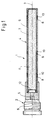
- a propellant charge for large-caliber cartridges ammunition referred to, consisting essentially of a head part 2 and a towards it in the direction the longitudinal axis 3 of the lighter 1 subsequent ignition tube 4 is made.
- the head part 2 which is an unillustrated primer and a booster charge 5 contains with an external thread 6 for screwing the propellant charge igniter 1 in the ground the corresponding cartridge (not shown) provided.
- the ignition tube 4 is composed of a jacket tube 7 made of steel with ignition openings 8 and an inside arranged seal in the form of a front side closed Protective tube 9 (e.g., a plastic or metal foil) together.
- a jacket tube 7 made of steel with ignition openings 8 and an inside arranged seal in the form of a front side closed Protective tube 9 (e.g., a plastic or metal foil) together.
- the protective tube 9 is with a powder or filled rod-shaped ignition charge 11 and covers the ignition openings 8 inside from.
- a e.g. hat-shaped cap 12 On its head part 2 facing the end of the protective tube 9 according to the invention by a e.g. hat-shaped cap 12 so tightly closed that no moisture can penetrate into the interior of the protective tube 9 in this area.
- FIGS 2-6 show different embodiments of such caps.
- closure caps 12 ' which are plate-shaped and glued to the head portion 2 of the TLAnz facing edge region 13 of the protective tube 9 or welded.
- the cap 12 ' can directly frontally with the Protective tube 9 be connected ( Figure 2) or it is from the folded edge area 13 of the protective tube 9 enclosed ( Figure 3).
- FIGS. 4 and 5 show hat-shaped closure caps 12 and 12 " .
- the closure cap 12 is provided with a brim 14 which is enclosed by the turned over edge region 13 of the protective tube 9.
- FIG. 6 shows a further embodiment of a hat-shaped closure cap 12 '" , which is provided on its side of the bottom 15 facing the ignition charge 11 with circular depressions 16 forming predetermined breaking points.
- the depressions do not necessarily have to be circular but may be another form, e.g. a circle-shaped figure, exhibit.
Abstract
Description
Die Erfindung betrifft einen Treibladungsanzünder für patronierte Munition mit einem Kopfteil und einem sich an das Kopfteil anschließendes, Anzündöffnungen aufweisendes Anzündrohr, in dem eine Anzündladung angeordnet ist.The invention relates to a propellant charge for cartridged ammunition with a Headboard and an adjoining the headboard, ignition openings exhibiting Ignition tube in which a Anzündladung is arranged.
In einem derartigen Treibladungsanzünder (TLAnz) müssen die empfindlichen explosiven Elemente der Anzündkette in geschützter, umhüllter Form vorliegen. Insbesondere ist eine Abdichtung der empfindlichen Anzündladung gegen Umwelteinflüsse erforderlich. So müssen die Anzündöffnungen und Gewindeteile des Anzündrohres zuverlässig abgedichtet sein, um die Funktion des TLAnz zu gewährleisten. Im Hinblick auf die Forderungen der Abnehmer entsprechender Munition muß die Abdichtung der Anzündladung mindestens 10 Jahre in feucht und feuchtaggressiven Klimaten zuverlässig gewährleistet sein, und zwar selbst dann, wenn die entsprechende Patrone nicht vollständig gegen Feuchtigkeit abgedichtet ist.In such a propellant charge igniter (TLAnz) must be the sensitive explosive Elements of the igniter chain are in protected, enveloped form. In particular, one is Sealing the sensitive ignition charge against environmental influences required. So the ignition openings and threaded parts of the ignition tube must be reliably sealed be to ensure the function of the TLAnz. With regard to the demands of Customers of appropriate ammunition must seal the ignition charge at least Be assured reliably for 10 years in humid and wet-aggressive climates, and though, even if the corresponding cartridge is not completely resistant to moisture is sealed.
Es ist bereits vorgeschlagen worden, zum Schutz der Anzündladung gegen äußere Umgebungseinflüsse innerhalb des Mantelrohres ein dünnwandiges Schutzrohr aus einer Kunststoff- oder Metallfolie anzuordnen, welches auf seiner dem Kopfteil abgewandten Seite geschlossen ist und dessen Außenwand an der Innenwand des Mantelrohres anliegt und die Anzündöffnungen innenseitig verdeckt.It has already been proposed to protect the ignition charge against external environmental influences within the jacket tube, a thin-walled protective tube made of a plastic or to arrange metal foil, which on its side facing away from the head part is closed and its outer wall rests against the inner wall of the jacket tube and the Ignition openings concealed on the inside.
Bei Überdruckversuchen hat sich indessen gezeigt, daß das Innere des Schutzrohres nicht vollständig wasserdicht ist, da vermutlich zwischen dem Mantelrohr und dem Schutzrohr Feuchtigkeit kopfteilseitig in das Schutzrohr und damit auch in die Anzündladung gelangt. In overpressure tests, however, has shown that the interior of the protective tube not completely waterproof, as probably between the jacket tube and the protective tube Moisture headboard side enters the protective tube and thus also in the ignition charge.
Der Erfindung liegt die Aufgabe zugrunde, einen Treibladungsanzünder anzugeben, der ein Anzündrohr mit einem innenseitig angeordneten Schutzrohr besitzt, welches auch bei erhöhter Feuchtelagerung über einen längeren Zeitraum die Anzündladung sicher gegen äußere Umgebungseinflüsse abdichtet.The invention has for its object to provide a propellant charge igniter, the one Ignition with an internally arranged protective tube has, which even at elevated Moisture storage over a longer period the ignition charge safe against external Environmental influences seals.
Diese Aufgabe wird erfindungsgemäß durch die Merkmale des Anspruchs 1 gelöst. Weitere, besonders vorteilhafte Ausgestaltungen der Erfindung offenbaren die Unteransprüche.This object is achieved by the features of claim 1. Further, Particularly advantageous embodiments of the invention disclose the dependent claims.
Die Erfindung beruht im wesentlichen auf dem Gedanken, das Schutzrohr auf seinem dem Kopfteil zugewandten Ende durch eine mit dem Schutzrohr kraftschlüssig verbundene Verschlußkappe gegen Feuchtigkeit abzudichten.The invention is based essentially on the idea of the protective tube on his Head end facing by a non-positively connected to the protective tube Seal cap against moisture.
Die Verwendung einer derartigen Verschlußkappe ermöglicht es außerdem, auf einfache Weise ein gekapseltes Schutzrohr mit Anzündladung vorzufertigen und diese Einheit auf Wasserdichtigkeit z.B. durch eine visuelle Überprüfung und eine Gewichtskontrolle zu prüfen.The use of such a cap also makes it easy to To prefabricate an enclosed thermowell with ignition charge and this unit on Waterproofness e.g. through a visual check and weight control too check.
Die Verschlußkappe kann beispielsweise als ebene Platte ausgebildet sein und mit dem dem Kopfteil zugewandten vorderen Rand des Schutzrohres verklebt oder verschweißt sein.The closure cap may be formed, for example, as a flat plate and with the glued or welded to the front part facing the front edge of the protective tube be.
Möglich ist es ferner, die Verschlußkappe hutförmig mit und ohne randseitige Krempe auszubilden.It is also possible, the cap hat-shaped with and without edge brim train.
Um ein sicheres Zünden der Anzündladung zu gewährleisten, hat es sich ferner als zweckmäßig erwiesen, wenn die der Anzündladung zugewandte Seite des Bodens der Verschlußkappe mit Sollbruchstellen bildenden Vertiefungen versehen ist.To ensure a safe ignition of the ignition charge, it has also as proven useful when the ignition of the side facing the bottom of the Cap is provided with predetermined breaking points forming depressions.
Schließlich ergibt sich ein weiterer Schutz gegen Feuchtigkeit, wenn die Anzündöffnungen des Mantelrohres mit stopfen- oder klipsartigen Elementen verschlossen werden, weil selbst im Fall einer nachträglichen Beschädigung des relativ dünnen Schutzrohres keine Feuchtigkeit durch diese Öffnungen in das Schutzrohr gelangen kann.Finally, there is a further protection against moisture when the ignition openings the jacket tube are closed with plug or clip-like elements, because even in the case of subsequent damage to the relatively thin protective tube no Moisture can pass through these openings in the protective tube.
Weitere Einzelheiten und Vorteile der Erfindung ergeben sich aus den folgenden anhand
von Figuren erläuterten Ausführungsbeispielen. Es zeigen:
In Fig.1 ist mit 1 ein Treibladungsanzünder für großkalibrige patronierte Panzermunition
bezeichnet, der im wesentlichen aus einem Kopfteil 2 und einem sich daran in Richtung
der Längsachse 3 des Anzünders 1 anschließenden Anzündrohr 4 besteht. Das Kopfteil 2,
welches ein nicht dargestelltes Anzündhütchen sowie eine Verstärkerladung 5 enthält, ist
mit einem Außengewinde 6 zum Einschrauben des Treibladungsanzünders 1 in den Boden
der entsprechenden Patrone (nicht dargestellt) versehen.In Fig.1 with 1 is a propellant charge for large-caliber cartridges ammunition
referred to, consisting essentially of a
Das Anzündrohr 4 setzt sich aus einem Mantelrohr 7 aus Stahl mit Anzündöffnungen 8 und
einer innenseitig angeordneten Abdichtung in Form eines vorderseitig geschlossenen
Schutzrohres 9 (z.B. aus einer Kunststoff- oder Metallfolie) zusammen. The ignition tube 4 is composed of a jacket tube 7 made of steel with
Um zu vermeiden, daß Feuchtigkeit von außen durch die Anzündöffnungen 8 eindringen
kann, sind die Anzündöffnungen 8 durch Stopfen 10 aus einem entsprechenden feuchtigkeitsundurchlässigen
Material verschlossen. Das Schutzrohr 9 ist mit einer pulver- oder
stangenförmigen Anzündladung 11 gefüllt und deckt die Anzündöffnungen 8 innenseitig
ab.To prevent moisture from entering through the
Auf seinem dem Kopfteil 2 zugewandten Ende ist das Schutzrohr 9 erfindungsgemäß
durch eine z.B. hutförmige Verschlußkappe 12 derart dicht verschlossen, daß keine Feuchtigkeit
in diesem Bereich in das Innere des Schutzrohres 9 eindringen kann.On its
Die Fig.2-6 zeigen unterschiedliche Ausgestaltungen derartiger Verschlußkappen.Figures 2-6 show different embodiments of such caps.
Dabei zeigen die Fig.2 und 3 Verschlußkappen 12', die plattenförmig ausgebildet sind und
mit dem dem Kopfteil 2 des TLAnz zugewandten Randbereich 13 des Schutzrohres 9 verklebt
oder verschweißt sind. Die Verschlußkappe 12' kann direkt stirnseitig mit dem
Schutzrohr 9 verbunden sein (Fig.2) oder sie wird von dem umgeschlagenen Randbereich
13 des Schutzrohres 9 umschlossen (Fig.3).2 and 3
Die Fig.4 und 5 zeigen hutförmig ausgebildete Verschlußkappen 12 und 12". Im Falle der
Fig.5 ist die Verschlußkappe 12 mit einer Krempe 14 versehen, die von dem umgeschlagenen
Randbereich 13 des Schutzrohres 9 umschlossen ist.4 and 5 show hat-
In Fig.6 ist ein weiteres Ausführungsbeispiel einer hutförmigen Verschlußkappe 12'" dargestellt,
die auf ihrer der Anzündladung 11 zugewandten Seite des Bodens 15 mit Sollbruchstellen
bildenden kreisförmigen Vertiefungen 16 versehen ist.6 shows a further embodiment of a hat-
Wie Fig.7 entnehmbar ist, müssen die Vertiefungen nicht zwingend kreisförmig ausgebildet sein, sondern können auch eine andere Form, z.B. eine kreisabschnittsförmig Gestalt, aufweisen. As can be seen from FIG. 7, the depressions do not necessarily have to be circular but may be another form, e.g. a circle-shaped figure, exhibit.
- 11
- Treibladungsanzündercharge igniter
- 22
- Kopfteilheadboard
- 33
- Längsachselongitudinal axis
- 44
- Anzündrohrignition tube
- 55
- Verstärkerladungbooster charge
- 66
- Außengewindeexternal thread
- 77
- Mantelrohrcasing pipe
- 88th
- AnzündöffnungAnzündöffnung
- 99
- Schutzrohrthermowell
- 1010
- Stopfen, ElementStopper, element
- 1111
- Anzündladungignition charge
- 12-12"'12-12 " '
- Verschlußkappencaps
- 1313
- Randbereichborder area
- 1414
- Krempebrim
- 1515
- Bodenground
- 16,16'16.16 '
- Vertiefungenwells
Claims (7)
Applications Claiming Priority (2)
| Application Number | Priority Date | Filing Date | Title |
|---|---|---|---|
| DE102004012934 | 2004-03-17 | ||
| DE102004012934A DE102004012934A1 (en) | 2004-03-17 | 2004-03-17 | charge igniter |
Publications (2)
| Publication Number | Publication Date |
|---|---|
| EP1577634A1 true EP1577634A1 (en) | 2005-09-21 |
| EP1577634B1 EP1577634B1 (en) | 2011-06-01 |
Family
ID=34833149
Family Applications (1)
| Application Number | Title | Priority Date | Filing Date |
|---|---|---|---|
| EP05001511A Active EP1577634B1 (en) | 2004-03-17 | 2005-01-26 | Igniter for propulsive charge |
Country Status (3)
| Country | Link |
|---|---|
| EP (1) | EP1577634B1 (en) |
| AT (1) | ATE511627T1 (en) |
| DE (1) | DE102004012934A1 (en) |
Cited By (2)
| Publication number | Priority date | Publication date | Assignee | Title |
|---|---|---|---|---|
| WO2009024243A1 (en) * | 2007-08-22 | 2009-02-26 | Rheinmetall Waffe Munition Gmbh | Propellant charge igniter |
| DE102022118632A1 (en) | 2022-07-26 | 2024-02-01 | Nitrochemie Aschau Gmbh | Shell and artillery charge |
Families Citing this family (1)
| Publication number | Priority date | Publication date | Assignee | Title |
|---|---|---|---|---|
| WO2010055089A1 (en) | 2008-11-13 | 2010-05-20 | Ruag Ammotec Gmbh | Pyrotechnic igniter |
Citations (9)
| Publication number | Priority date | Publication date | Assignee | Title |
|---|---|---|---|---|
| FR866800A (en) * | 1940-05-09 | 1941-09-03 | Method and devices for protecting sheath bodies | |
| GB605135A (en) * | 1945-12-14 | 1948-07-16 | John Norman Pring | Improvements in or relating to magazines or containers for cartridge priming compositions |
| US2446187A (en) * | 1945-05-07 | 1948-08-03 | Leo T Meister | Lined igniter-charge tube |
| DE2344979A1 (en) * | 1973-09-06 | 1975-03-20 | Dynamit Nobel Ag | Flange closure for igniter housing - has shoulder bent round inwards to press cover against conical step |
| FR2343987A1 (en) * | 1976-03-08 | 1977-10-07 | France Etat | Tubular primer for artillery ammunition propellant - has axial bore and side vents through combustible ensuring uniform ignition |
| US4284196A (en) * | 1978-10-04 | 1981-08-18 | Nitro Nobel Ab | Tubular container for viscous, viscous-elastic, plastic products as well as for powder or granular products |
| EP0390756A2 (en) * | 1989-03-02 | 1990-10-03 | Ab Bofors | Primer for a propellant charge |
| EP1039260A2 (en) * | 1996-08-02 | 2000-09-27 | Rheinmetall W & M GmbH | Primer for propulsive charge |
| WO2001071274A1 (en) * | 2000-03-23 | 2001-09-27 | Giat Industries | Igniter tube for artillery ammunition |
-
2004
- 2004-03-17 DE DE102004012934A patent/DE102004012934A1/en not_active Withdrawn
-
2005
- 2005-01-26 EP EP05001511A patent/EP1577634B1/en active Active
- 2005-01-26 AT AT05001511T patent/ATE511627T1/en active
Patent Citations (9)
| Publication number | Priority date | Publication date | Assignee | Title |
|---|---|---|---|---|
| FR866800A (en) * | 1940-05-09 | 1941-09-03 | Method and devices for protecting sheath bodies | |
| US2446187A (en) * | 1945-05-07 | 1948-08-03 | Leo T Meister | Lined igniter-charge tube |
| GB605135A (en) * | 1945-12-14 | 1948-07-16 | John Norman Pring | Improvements in or relating to magazines or containers for cartridge priming compositions |
| DE2344979A1 (en) * | 1973-09-06 | 1975-03-20 | Dynamit Nobel Ag | Flange closure for igniter housing - has shoulder bent round inwards to press cover against conical step |
| FR2343987A1 (en) * | 1976-03-08 | 1977-10-07 | France Etat | Tubular primer for artillery ammunition propellant - has axial bore and side vents through combustible ensuring uniform ignition |
| US4284196A (en) * | 1978-10-04 | 1981-08-18 | Nitro Nobel Ab | Tubular container for viscous, viscous-elastic, plastic products as well as for powder or granular products |
| EP0390756A2 (en) * | 1989-03-02 | 1990-10-03 | Ab Bofors | Primer for a propellant charge |
| EP1039260A2 (en) * | 1996-08-02 | 2000-09-27 | Rheinmetall W & M GmbH | Primer for propulsive charge |
| WO2001071274A1 (en) * | 2000-03-23 | 2001-09-27 | Giat Industries | Igniter tube for artillery ammunition |
Cited By (4)
| Publication number | Priority date | Publication date | Assignee | Title |
|---|---|---|---|---|
| WO2009024243A1 (en) * | 2007-08-22 | 2009-02-26 | Rheinmetall Waffe Munition Gmbh | Propellant charge igniter |
| US9016203B2 (en) | 2007-08-22 | 2015-04-28 | Rheinmetall Waffe Munition Gmbh | Propellant charge igniter |
| DE102022118632A1 (en) | 2022-07-26 | 2024-02-01 | Nitrochemie Aschau Gmbh | Shell and artillery charge |
| DE102022118632B4 (en) | 2022-07-26 | 2024-03-21 | Nitrochemie Aschau Gmbh | Shell and artillery charge |
Also Published As
| Publication number | Publication date |
|---|---|
| EP1577634B1 (en) | 2011-06-01 |
| ATE511627T1 (en) | 2011-06-15 |
| DE102004012934A1 (en) | 2005-10-06 |
Similar Documents
| Publication | Publication Date | Title |
|---|---|---|
| DE102004059991A1 (en) | irritation body | |
| DE2842797A1 (en) | THROWING BODY | |
| EP1577634B1 (en) | Igniter for propulsive charge | |
| WO2012126554A1 (en) | Non-sensitive ammunition | |
| EP1067358B1 (en) | Igniter for a propulsive charge | |
| DE2932922C2 (en) | Smoke missile | |
| EP1484574A1 (en) | Safety bomb container | |
| DE2911595A1 (en) | ARRANGEMENT ON A BUSTER CAP OF A LOW ENERGY CONNECTOR | |
| EP3006889B1 (en) | Chemical igniter with electric triggering | |
| EP3479051A1 (en) | Stun grenade and method for production thereof | |
| DE1728018A1 (en) | Semi-flammable ammunition for locks of the open chamber type | |
| DE1814099C3 (en) | Explosion-proof cup capacitor | |
| DE2446832C2 (en) | Ignition device for launcher tubes for igniting the propulsion charge of a projectile | |
| DE60107181T2 (en) | METHOD FOR NEUTRALIZING A USE LOAD | |
| DE2031940A1 (en) | Safety device for hand grenades | |
| EP0733874B1 (en) | Device for simulating a projectile and manufacturing method for making such a device | |
| EP2146179A2 (en) | Smoke pot | |
| AT396304B (en) | Practice hand grenade detonator (fuze) | |
| DE4444095C2 (en) | Band-shaped loading strip for bolt-setting tools | |
| AT393561B (en) | Safety device for land mines | |
| DE3434650A1 (en) | Container insertable into a projectile | |
| DE3048621A1 (en) | Window cartridge with charge in glass fibre reinforced plastics case - has closure protecting metallised threads of various lengths from handling shock | |
| EP2705328A1 (en) | Explosive material container | |
| EP1471268A1 (en) | Fracture bolt | |
| AT253388B (en) | Land mine, especially anti-tank mine |
Legal Events
| Date | Code | Title | Description |
|---|---|---|---|
| PUAI | Public reference made under article 153(3) epc to a published international application that has entered the european phase |
Free format text: ORIGINAL CODE: 0009012 |
|
| AK | Designated contracting states |
Kind code of ref document: A1 Designated state(s): AT BE BG CH CY CZ DE DK EE ES FI FR GB GR HU IE IS IT LI LT LU MC NL PL PT RO SE SI SK TR |
|
| AX | Request for extension of the european patent |
Extension state: AL BA HR LV MK YU |
|
| 17P | Request for examination filed |
Effective date: 20060307 |
|
| AKX | Designation fees paid |
Designated state(s): AT BE BG CH CY CZ DE DK EE ES FI FR GB GR HU IE IS IT LI LT LU MC NL PL PT RO SE SI SK TR |
|
| RAP1 | Party data changed (applicant data changed or rights of an application transferred) |
Owner name: RHEINMETALL WAFFE MUNITION GMBH |
|
| GRAP | Despatch of communication of intention to grant a patent |
Free format text: ORIGINAL CODE: EPIDOSNIGR1 |
|
| GRAS | Grant fee paid |
Free format text: ORIGINAL CODE: EPIDOSNIGR3 |
|
| GRAA | (expected) grant |
Free format text: ORIGINAL CODE: 0009210 |
|
| AK | Designated contracting states |
Kind code of ref document: B1 Designated state(s): AT BE BG CH CY CZ DE DK EE ES FI FR GB GR HU IE IS IT LI LT LU MC NL PL PT RO SE SI SK TR |
|
| REG | Reference to a national code |
Ref country code: GB Ref legal event code: FG4D Free format text: NOT ENGLISH |
|
| REG | Reference to a national code |
Ref country code: CH Ref legal event code: EP |
|
| REG | Reference to a national code |
Ref country code: IE Ref legal event code: FG4D Free format text: LANGUAGE OF EP DOCUMENT: GERMAN |
|
| REG | Reference to a national code |
Ref country code: DE Ref legal event code: R096 Ref document number: 502005011448 Country of ref document: DE Effective date: 20110714 |
|
| REG | Reference to a national code |
Ref country code: NL Ref legal event code: VDEP Effective date: 20110601 |
|
| PG25 | Lapsed in a contracting state [announced via postgrant information from national office to epo] |
Ref country code: LT Free format text: LAPSE BECAUSE OF FAILURE TO SUBMIT A TRANSLATION OF THE DESCRIPTION OR TO PAY THE FEE WITHIN THE PRESCRIBED TIME-LIMIT Effective date: 20110601 Ref country code: SE Free format text: LAPSE BECAUSE OF FAILURE TO SUBMIT A TRANSLATION OF THE DESCRIPTION OR TO PAY THE FEE WITHIN THE PRESCRIBED TIME-LIMIT Effective date: 20110601 |
|
| PG25 | Lapsed in a contracting state [announced via postgrant information from national office to epo] |
Ref country code: FI Free format text: LAPSE BECAUSE OF FAILURE TO SUBMIT A TRANSLATION OF THE DESCRIPTION OR TO PAY THE FEE WITHIN THE PRESCRIBED TIME-LIMIT Effective date: 20110601 Ref country code: CY Free format text: LAPSE BECAUSE OF FAILURE TO SUBMIT A TRANSLATION OF THE DESCRIPTION OR TO PAY THE FEE WITHIN THE PRESCRIBED TIME-LIMIT Effective date: 20110601 Ref country code: GR Free format text: LAPSE BECAUSE OF FAILURE TO SUBMIT A TRANSLATION OF THE DESCRIPTION OR TO PAY THE FEE WITHIN THE PRESCRIBED TIME-LIMIT Effective date: 20110902 Ref country code: ES Free format text: LAPSE BECAUSE OF FAILURE TO SUBMIT A TRANSLATION OF THE DESCRIPTION OR TO PAY THE FEE WITHIN THE PRESCRIBED TIME-LIMIT Effective date: 20110912 Ref country code: SI Free format text: LAPSE BECAUSE OF FAILURE TO SUBMIT A TRANSLATION OF THE DESCRIPTION OR TO PAY THE FEE WITHIN THE PRESCRIBED TIME-LIMIT Effective date: 20110601 |
|
| REG | Reference to a national code |
Ref country code: IE Ref legal event code: FD4D |
|
| PG25 | Lapsed in a contracting state [announced via postgrant information from national office to epo] |
Ref country code: NL Free format text: LAPSE BECAUSE OF FAILURE TO SUBMIT A TRANSLATION OF THE DESCRIPTION OR TO PAY THE FEE WITHIN THE PRESCRIBED TIME-LIMIT Effective date: 20110601 |
|
| PG25 | Lapsed in a contracting state [announced via postgrant information from national office to epo] |
Ref country code: PT Free format text: LAPSE BECAUSE OF FAILURE TO SUBMIT A TRANSLATION OF THE DESCRIPTION OR TO PAY THE FEE WITHIN THE PRESCRIBED TIME-LIMIT Effective date: 20111003 Ref country code: CZ Free format text: LAPSE BECAUSE OF FAILURE TO SUBMIT A TRANSLATION OF THE DESCRIPTION OR TO PAY THE FEE WITHIN THE PRESCRIBED TIME-LIMIT Effective date: 20110601 Ref country code: IE Free format text: LAPSE BECAUSE OF FAILURE TO SUBMIT A TRANSLATION OF THE DESCRIPTION OR TO PAY THE FEE WITHIN THE PRESCRIBED TIME-LIMIT Effective date: 20110601 Ref country code: EE Free format text: LAPSE BECAUSE OF FAILURE TO SUBMIT A TRANSLATION OF THE DESCRIPTION OR TO PAY THE FEE WITHIN THE PRESCRIBED TIME-LIMIT Effective date: 20110601 Ref country code: IS Free format text: LAPSE BECAUSE OF FAILURE TO SUBMIT A TRANSLATION OF THE DESCRIPTION OR TO PAY THE FEE WITHIN THE PRESCRIBED TIME-LIMIT Effective date: 20111001 |
|
| PG25 | Lapsed in a contracting state [announced via postgrant information from national office to epo] |
Ref country code: RO Free format text: LAPSE BECAUSE OF FAILURE TO SUBMIT A TRANSLATION OF THE DESCRIPTION OR TO PAY THE FEE WITHIN THE PRESCRIBED TIME-LIMIT Effective date: 20110601 Ref country code: PL Free format text: LAPSE BECAUSE OF FAILURE TO SUBMIT A TRANSLATION OF THE DESCRIPTION OR TO PAY THE FEE WITHIN THE PRESCRIBED TIME-LIMIT Effective date: 20110601 Ref country code: SK Free format text: LAPSE BECAUSE OF FAILURE TO SUBMIT A TRANSLATION OF THE DESCRIPTION OR TO PAY THE FEE WITHIN THE PRESCRIBED TIME-LIMIT Effective date: 20110601 |
|
| PLBE | No opposition filed within time limit |
Free format text: ORIGINAL CODE: 0009261 |
|
| STAA | Information on the status of an ep patent application or granted ep patent |
Free format text: STATUS: NO OPPOSITION FILED WITHIN TIME LIMIT |
|
| 26N | No opposition filed |
Effective date: 20120302 |
|
| PG25 | Lapsed in a contracting state [announced via postgrant information from national office to epo] |
Ref country code: IT Free format text: LAPSE BECAUSE OF FAILURE TO SUBMIT A TRANSLATION OF THE DESCRIPTION OR TO PAY THE FEE WITHIN THE PRESCRIBED TIME-LIMIT Effective date: 20110601 |
|
| REG | Reference to a national code |
Ref country code: DE Ref legal event code: R097 Ref document number: 502005011448 Country of ref document: DE Effective date: 20120302 |
|
| PG25 | Lapsed in a contracting state [announced via postgrant information from national office to epo] |
Ref country code: DK Free format text: LAPSE BECAUSE OF FAILURE TO SUBMIT A TRANSLATION OF THE DESCRIPTION OR TO PAY THE FEE WITHIN THE PRESCRIBED TIME-LIMIT Effective date: 20110601 |
|
| BERE | Be: lapsed |
Owner name: RHEINMETALL WAFFE MUNITION G.M.B.H. Effective date: 20120131 |
|
| PG25 | Lapsed in a contracting state [announced via postgrant information from national office to epo] |
Ref country code: MC Free format text: LAPSE BECAUSE OF NON-PAYMENT OF DUE FEES Effective date: 20120131 |
|
| REG | Reference to a national code |
Ref country code: CH Ref legal event code: PL |
|
| PG25 | Lapsed in a contracting state [announced via postgrant information from national office to epo] |
Ref country code: LI Free format text: LAPSE BECAUSE OF NON-PAYMENT OF DUE FEES Effective date: 20120131 Ref country code: CH Free format text: LAPSE BECAUSE OF NON-PAYMENT OF DUE FEES Effective date: 20120131 |
|
| PG25 | Lapsed in a contracting state [announced via postgrant information from national office to epo] |
Ref country code: BE Free format text: LAPSE BECAUSE OF NON-PAYMENT OF DUE FEES Effective date: 20120131 |
|
| REG | Reference to a national code |
Ref country code: AT Ref legal event code: MM01 Ref document number: 511627 Country of ref document: AT Kind code of ref document: T Effective date: 20120126 |
|
| PG25 | Lapsed in a contracting state [announced via postgrant information from national office to epo] |
Ref country code: BG Free format text: LAPSE BECAUSE OF FAILURE TO SUBMIT A TRANSLATION OF THE DESCRIPTION OR TO PAY THE FEE WITHIN THE PRESCRIBED TIME-LIMIT Effective date: 20110901 Ref country code: AT Free format text: LAPSE BECAUSE OF NON-PAYMENT OF DUE FEES Effective date: 20120126 |
|
| PG25 | Lapsed in a contracting state [announced via postgrant information from national office to epo] |
Ref country code: TR Free format text: LAPSE BECAUSE OF FAILURE TO SUBMIT A TRANSLATION OF THE DESCRIPTION OR TO PAY THE FEE WITHIN THE PRESCRIBED TIME-LIMIT Effective date: 20110601 |
|
| PG25 | Lapsed in a contracting state [announced via postgrant information from national office to epo] |
Ref country code: LU Free format text: LAPSE BECAUSE OF NON-PAYMENT OF DUE FEES Effective date: 20120126 |
|
| PG25 | Lapsed in a contracting state [announced via postgrant information from national office to epo] |
Ref country code: HU Free format text: LAPSE BECAUSE OF FAILURE TO SUBMIT A TRANSLATION OF THE DESCRIPTION OR TO PAY THE FEE WITHIN THE PRESCRIBED TIME-LIMIT Effective date: 20050126 |
|
| REG | Reference to a national code |
Ref country code: FR Ref legal event code: PLFP Year of fee payment: 12 |
|
| REG | Reference to a national code |
Ref country code: FR Ref legal event code: PLFP Year of fee payment: 13 |
|
| REG | Reference to a national code |
Ref country code: FR Ref legal event code: PLFP Year of fee payment: 14 |
|
| REG | Reference to a national code |
Ref country code: DE Ref legal event code: R082 Ref document number: 502005011448 Country of ref document: DE Representative=s name: DREISS PATENTANWAELTE PARTG MBB, DE |
|
| REG | Reference to a national code |
Ref country code: DE Ref legal event code: R082 Ref document number: 502005011448 Country of ref document: DE Representative=s name: DREISS PATENTANWAELTE PARTG MBB, DE |
|
| PGFP | Annual fee paid to national office [announced via postgrant information from national office to epo] |
Ref country code: FR Payment date: 20230124 Year of fee payment: 19 |
|
| PGFP | Annual fee paid to national office [announced via postgrant information from national office to epo] |
Ref country code: GB Payment date: 20230119 Year of fee payment: 19 Ref country code: DE Payment date: 20220620 Year of fee payment: 19 |