EP1576858B1 - Supply assembly for a led lighting module - Google Patents
Supply assembly for a led lighting module Download PDFInfo
- Publication number
- EP1576858B1 EP1576858B1 EP03777081A EP03777081A EP1576858B1 EP 1576858 B1 EP1576858 B1 EP 1576858B1 EP 03777081 A EP03777081 A EP 03777081A EP 03777081 A EP03777081 A EP 03777081A EP 1576858 B1 EP1576858 B1 EP 1576858B1
- Authority
- EP
- European Patent Office
- Prior art keywords
- current
- high frequency
- switching signal
- low frequency
- pwm switching
- Prior art date
- Legal status (The legal status is an assumption and is not a legal conclusion. Google has not performed a legal analysis and makes no representation as to the accuracy of the status listed.)
- Expired - Lifetime
Links
- 230000009977 dual effect Effects 0.000 claims abstract description 15
- 238000009877 rendering Methods 0.000 claims 1
- 238000010586 diagram Methods 0.000 description 14
- 238000001514 detection method Methods 0.000 description 4
- 239000003990 capacitor Substances 0.000 description 3
- 230000000712 assembly Effects 0.000 description 2
- 238000000429 assembly Methods 0.000 description 2
Images


Classifications
-
- H—ELECTRICITY
- H05—ELECTRIC TECHNIQUES NOT OTHERWISE PROVIDED FOR
- H05B—ELECTRIC HEATING; ELECTRIC LIGHT SOURCES NOT OTHERWISE PROVIDED FOR; CIRCUIT ARRANGEMENTS FOR ELECTRIC LIGHT SOURCES, IN GENERAL
- H05B45/00—Circuit arrangements for operating light-emitting diodes [LED]
- H05B45/30—Driver circuits
- H05B45/32—Pulse-control circuits
- H05B45/327—Burst dimming
-
- H—ELECTRICITY
- H05—ELECTRIC TECHNIQUES NOT OTHERWISE PROVIDED FOR
- H05B—ELECTRIC HEATING; ELECTRIC LIGHT SOURCES NOT OTHERWISE PROVIDED FOR; CIRCUIT ARRANGEMENTS FOR ELECTRIC LIGHT SOURCES, IN GENERAL
- H05B45/00—Circuit arrangements for operating light-emitting diodes [LED]
- H05B45/10—Controlling the intensity of the light
-
- H—ELECTRICITY
- H05—ELECTRIC TECHNIQUES NOT OTHERWISE PROVIDED FOR
- H05B—ELECTRIC HEATING; ELECTRIC LIGHT SOURCES NOT OTHERWISE PROVIDED FOR; CIRCUIT ARRANGEMENTS FOR ELECTRIC LIGHT SOURCES, IN GENERAL
- H05B45/00—Circuit arrangements for operating light-emitting diodes [LED]
- H05B45/30—Driver circuits
- H05B45/37—Converter circuits
- H05B45/3725—Switched mode power supply [SMPS]
-
- F—MECHANICAL ENGINEERING; LIGHTING; HEATING; WEAPONS; BLASTING
- F21—LIGHTING
- F21W—INDEXING SCHEME ASSOCIATED WITH SUBCLASSES F21K, F21L, F21S and F21V, RELATING TO USES OR APPLICATIONS OF LIGHTING DEVICES OR SYSTEMS
- F21W2107/00—Use or application of lighting devices on or in particular types of vehicles
-
- F—MECHANICAL ENGINEERING; LIGHTING; HEATING; WEAPONS; BLASTING
- F21—LIGHTING
- F21W—INDEXING SCHEME ASSOCIATED WITH SUBCLASSES F21K, F21L, F21S and F21V, RELATING TO USES OR APPLICATIONS OF LIGHTING DEVICES OR SYSTEMS
- F21W2111/00—Use or application of lighting devices or systems for signalling, marking or indicating, not provided for in codes F21W2102/00 – F21W2107/00
- F21W2111/02—Use or application of lighting devices or systems for signalling, marking or indicating, not provided for in codes F21W2102/00 – F21W2107/00 for roads, paths or the like
-
- H—ELECTRICITY
- H05—ELECTRIC TECHNIQUES NOT OTHERWISE PROVIDED FOR
- H05B—ELECTRIC HEATING; ELECTRIC LIGHT SOURCES NOT OTHERWISE PROVIDED FOR; CIRCUIT ARRANGEMENTS FOR ELECTRIC LIGHT SOURCES, IN GENERAL
- H05B45/00—Circuit arrangements for operating light-emitting diodes [LED]
- H05B45/30—Driver circuits
- H05B45/37—Converter circuits
- H05B45/3725—Switched mode power supply [SMPS]
- H05B45/375—Switched mode power supply [SMPS] using buck topology
Abstract
Description
- The subject invention relates to a supply assembly for supplying power to a light emitting diode (LED) lighting module. Such supply assemblies are disclosed for instance in
US-B1-6329760 andEP-A-948241 - LED lighting modules are becoming more common in many applications for replacing less efficient incandescent lamps, for example, in traffic signal lights and automobile lighting. Depending on the amount of light required in the application, the LED lighting modules may consist of a plurality LED's arranged in parallel or in series, or a combination of both. In either case, the LED lighting module receives operating power from a supply assembly that switches a direct current voltage on and off at a high frequency. Such supply assemblies are known as switched-mode power supplies and are available in a plurality of forms, for example, a flyback converter, a buck converter, a half-bridge converter, etc. Each of these converters is capable of supplying a constant current to the LED lighting module in the form of a pulse width modulated signal.
- In the use of LED lighting modules, it is desirable to be able to control the intensity of the light being output by the LED lighting module. This may be achieved in a number of ways. For example, the amount of current delivered to the LED lighting module may be adjusted by controlling the pulse width modulation. However, once the current intensity drops below 20% of the nominal current intensity, the relation between the current intensity and the light output becomes largely non-linear, and the efficiency of the LED lighting module becomes far from optimal.
-
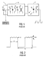
U.S. Patent 5,661,645 describes a power supply for a light emitting diode array which includes a circuit for interrupting the supply of power from the power supply to the LED array. As shown inFig. 1 herein, the power supply 1 includes a supply of directcurrent voltage 10, which may be a battery or rectified line alternating current (AC) voltage connected to a switched-mode converter 12 typically having acontrol switch 14, adiode 16, aninductor 18, anoptional capacitor 20 and anoptional transformer 22. A control input of thecontrol switch 14 receives a high frequency pulse-width modulated (PWM) switching signal. Outputs from the power supply 1 are connected to anLED lighting module 2 having an LED array 24 (shown herein as a single LED) and acontrollable switch 26 for interrupting the supply of power to theLED array 24. Thecontrollable switch 26 receives a low frequency PWM switching signal for controlling the mean current to theLED array 24.Fig. 2 shows a plot of the current through theLED array 24 in which the low frequency PWM switching signal causes current pulses D occurring in the period FD, an the high frequency PWM switching signal causes the current variation AID While this arrangement ensures that the LED array always operates in an efficient manner, it should be understood that the power supply 1 is continually on even when the PWM switching signal has thecontrollable switch 26 turned off.Fig. 3 shows an equivalent circuit of the arrangement ofFig. 1 . As should be apparent, while the power from the DC source is stopped when thecontrol switch 14 is open, such is not the case when thecontrollable switch 26 is open. As such, this arrangement suffers from an unnecessary loss of energy. - Published
U.S. Patent Application No. 2001/0024112A1 discloses an alternate arrangement to that shown inU.S. Patent 5,661,645 . In this alternate arrangement, the power supply itself is turned on an off using the low frequency PWM switching signal.Fig. 4 shows an example of this alternate arrangement. Similarly as inFig. 1 , the power supply 1' includes a supply of directcurrent voltage 10, which may be a battery or rectified line alternating current (AC) voltage connected to a switched-mode converter 12' typically having acontrol switch 14, adiode 16, aninductor 18, anoptional capacitor 20 and anoptional transformer 22. A control input of thecontrol switch 14 receives a high frequency pulse-width modulated (PWM) switching signal. Outputs from the power supply 1' are connected to an LED lighting module 2' having an LED array 24 (shown herein as a single LED). The LED lighting module 2' does not include thecontrollable switch 26 shown inFig. 1 . Rather, the switched-mode converter 12' includes an input for receiving the low frequency PWM switching signal which effectively controls means for turning on and off the switched-mode converter 12'. - It is an object of the subject invention to eliminate the means for switching on and off the power supply to an LED array while still effecting the low frequency pulse width modulation of the current to the LED array.
- This object is achieved in a supply assembly for a LED lighting module comprising a direct current (DC) voltage source having a first and a second supply terminal; a series arrangement of a diode and a controllable switch connected across the first and second supply terminals of the DC voltage source; an inductor connecting the first supply terminal of the DC voltage source to an first output terminal, a node between the diode and the controllable switch forming a second output terminal, said LED lighting module being connectable between the first and second output terminals; and a controller for controlling the switching of the controllable switch, said controller having means for supplying a dual pulse-width modulated switching signal to said controllable switch at two frequencies including a high frequency pulse-width modulated switching signal component for controlling a magnitude of the LED current, and a low frequency pulse-width modulated switching signal component for controlling a duration of the LED current.
- Applicants have found that the control switch in the switched-mode power supply may be used for both the high frequency PWM switching as well as the low frequency PWM switching thereby eliminating the need for separate means for switching the power supply on and off. To that end, the supply signal to the control switch includes both the high frequency PWM switching signal as well as the low frequency PWM switching signal, i.e., the high frequency switching signal is applied in pulse bursts at the low frequency to the control switch.
- Applicants have further found that when the power supply is switched on and off by separate means, there is a gradual increase and decrease in the duty cycle, while when a dual PWM switching signal is applied to the control switch, the change in the duty cycle is instantaneous.
- In a further embodiment of the subject invention, the controller further comprises an input for receiving a current signal indicative of the LED current, and means for modifying said low frequency pulse-width modulated switching signal component in dependence on said current signal.
- Applicants have found that by detecting the LED current, the duty cycle of the high frequency PWM switching signal component may quickly respond to the LED current leading to the fastest rise/fall time of the LED current.
- With the above and additional object and advantages in mind as will hereinafter appear, the subject invention will be described with reference to the accompanying drawings, in which:
-
Fig. 1 shows a generic block circuit diagram of a prior art power supply for an LED array; -
Fig. 2 shows a graph of the current through the LED array ofFig. 1 ; -
Fig. 3 shows an equivalent circuit of the power supply ofFig. 1 ; -
Fig. 4 shows a generic block circuit diagram of another prior art power supply for an LED array; -
Fig. 5 shows a generic block circuit diagram of a power supply for an LED array incorporating the subject invention; -
Fig. 6 shows a graph of the dual PWM control signal for the power supply ofFig. 5 ; -
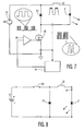
Fig. 7 shows a block circuit diagram of a buck converter for an LED array incorporating the subject invention; -
Fig. 8 shows an equivalent circuit of the power supply ofFig. 7 ; -
Fig. 9 shows a block circuit diagram of the power supply ofFig. 7 , showing a first embodiment of the controller; -
Fig. 10 shows a block circuit diagram of the power supply ofFig. 7 , showing a second embodiment of the controller; -
Fig. 11 shows a block circuit diagram of the power supply ofFig. 7 , showing a third embodiment of the controller; and -
Fig. 12A shows a graph of the LED current,Fig. 12B shows the details of the LED current at turn off, andFig. 12C shows the details of the LED current at turn on. -
Fig. 5 shows a generic block circuit diagram of the power supply and LED lighting module of the subject invention. In particular, similarly as inFigs. 1 and4 , the power supply 1" includes a supply of directcurrent voltage 10, which may be a battery or rectified line alternating current (AC) voltage connected to a switched-mode converter 12" typically having acontrol switch 14, adiode 16, aninductor 18, anoptional capacitor 20 and anoptional transformer 22. Outputs from the power supply 1" are connected to an LED lighting module 2' having anLED array 24. A control input of thecontrol switch 14 now receives a dual PWM switching signal. As is more clearly shown inFig. 6 , this dual PWM switching signal is, in essence, a combination of a high frequency PWM switching signal component which is applied in pulse bursts at a low frequency, i.e., the low frequency PWM switching component. -
Fig. 7 shows a block circuit diagram of a buck converter for an LED array incorporating the subject invention. In particular, aDC supply 10 is connected across the series arrangement of a diode D1 and acontrol switch 30, shown as a MOSFET, while a series arrangement of aninductor 32 and the LED lighting module 2' is connected across the diode D1. Acontroller 34 generates the dual PWM switching signal which is applied, via anamplifier 36 to a control input of thecontrol switch 30. Thecontroller 34 has an input for receiving a signal indicative of the current sensed in the drain terminal of thecontrol switch 30, which is related to the LED current. Alternatively, as shown in dotted line, this input may receive a signal indicative of the sensed LED current. -
Fig. 8 shows an equivalent circuit diagram of the power supply/LED lighting module ofFig. 7 . It should be apparent that in this configuration, the inductor current always ramps down to zero when the control switch is turned off, thereby avoiding the current circulation problems of the circuit diagram ofFig. 3 when the controllable switch is turned off. -
Fig. 9 shows the block circuit diagram ofFig. 7 with a first embodiment of thecontroller 34. In particular, thecontroller 34 includes a current modepulse width modulator 38 which receives an LED current reference signal from acurrent source 40, the sensed current, and a high frequency sawtooth signal. The current modepulse width modulator 38 then supplies the high frequency pulse width modulated switching signal component which is applied to one input of an AND-gate 42, the other input of which receives the low frequency PWM switching signal component. The output from the AND-gate 42 is then applied through theamplifier 36 to the gate of thecontrol switch 30. -
Fig. 10 shows the block circuit diagram ofFig. 7 , with a second embodiment of thecontroller 34. In particular, thecontroller 34 includes anadder 44 having a positive input for receiving a reference voltage VREF and a negative input for receiving a high frequency ramp signal. An output from theadder 44 is applied to an inverting input of acomparator 46 which receives the sensed current at its non-inverting input. An output of thecomparator 46 is applied to the reset input of an RS flip-flop 48 which receives a high frequency clock signal at its set input. The Q output from the RS flip-flop 48 is applied to one input of an AND-gate 50 which receives the low frequency PWM switching signal component at its other input. The output from the AND-gate 50 is then applied through theamplifier 36 to the gate of thecontrol switch 30. - In the embodiment of
Fig. 9 , either peak or average current detection may be used, while in the embodiment ofFig. 10 , peak current detection is used. -
Fig. 11 shows the block circuit diagram ofFig. 7 , showing a third embodiment of thecontroller 34 in which both peak current detection and average current detection are used. In particular, the sensed current is applied to anintegrator 52 which forms an average of the sensed current. An output of theintegrator 52 is applied to a low frequencypulse width modulator 54 which receives a reference current fromcurrent source 56 and a low frequency sawtooth signal from low frequencysawtooth generator 58 which has auser control 60 coupled thereto. An output from the low frequencypulse width modulator 54 is applied to a first input of an AND-gate 62. The sensed current is also applied to a sample-and-hold circuit 64. An output from the sample-and-hold circuit 64, which represents the peak sensed current, is applied to a high frequencypulse width modulator 66 which also receives a reference current fromcurrent source 68 and a high frequency sawtooth signal from high frequencysawtooth generator 70. The output from the high frequencypulse width modulator 66 is applied to the second input of the AND-gate 62, and the output from the AND-gate 62 is then applied through theamplifier 36 to the gate of thecontrol switch 30. - In operation, the user sets a desired intensity level for the LED lighting module using the
user control 58. The resulting sawtooth signal (varying in, for example, the duration of each sawtooth) generated by the low frequencysawtooth generator 56 is applied to the low frequencypulse width modulator 54. In dependence on this sawtooth signal, the reference current, and the average LED current, the low frequency pulse width modulator generates the low frequency PWM switching signal component with the appropriate pulse width. At the same time, the sensed current is applied and stored in the sample-and-hold circuit 62. The output from the sample-and-hold circuit 62, along with the reference current and the high frequency sawtooth signal are processed by the high frequencypulse width modulator 64 to adjust the pulse width of the high frequency PWM switching signal component. The AND-gate 60 then combines the high frequency and low frequency PWM switching signal components to form the dual PWM switching signal which is applied, via theamplifier 36 to the gate of thecontrol switch 30. -
Fig. 12A shows the overall LED current.Fig. 12B shows the LED current at the end of, for example, the first pulse inFig. 12A , as compared with the dual switching signal ofFig. 6 . For comparison,Fig. 12B also shows the LED current (dotted line) if, instead, the power supply were merely turned off, which then exhibits ringing. Finally,Fig. 12C shows the LED current at the beginning of, for example, the second pulse inFig. 12A , as compared with the dual switching signal ofFig. 6 . For comparison,Fig. 12C also shows the LED current (dotted line) if, instead, the power supply were merely turned on.
Claims (6)
- A supply assembly(1") for a LED lighting module (2') comprising:a direct current (DC) voltage source (10) having a first and a second supply terminal;a switched-mode converter (12")connected to said first and second supply terminals for supplying power to an LED lighting module (2') connectable to said switched mode converter, said switched mode converter comprising a controllable switch (14) coupled to at least one of said first and second supply terminals for switchably connecting said DC voltage source and said converter being constructed so that the LED lighting module can conduct a current both when the controllable switch is conductive and when the controllable switch is non-conductive; anda controller (34) for controlling the switching of the controllable switch (14) by means of a dual pulse width modulated signal, such that a periodical LED current is generated, said LED current being continuous with a superimposed ripple during a first time interval of each period and equal to zero during the remainder of each period, said controller (34) comprising means for supplying a high frequency pulse width modulated signal to said controllable switch during the first time interval of each period of the LED current for controlling the average amplitude of the LED current during the first time interval and the duration of the first time interval and means for rendering the controllable switch non-conductive during the remainder of each period of the LED current.
- The supply assembly (1") for a LED lighting module of claim 1, comprising:a series arrangement of a diode (D1) operating as a free-wheeling diode and a controllable switch (30) connected across the first and second supply terminals of the DC voltage source; andan inductor (32)connecting the first supply terminal of the DC voltage source (10) to an first output terminal, a node between the diode (D1) and the controllable switch (30) forming a second output terminal, said LED lighting module being connectable between the first and second output terminals.
- The supply assembly (1") as claimed in claim 2, wherein the controller (34) further comprises an input for receiving a sensed current indicative of the LED current, and means (38) for modifying said low frequency pulse-width modulated switching signal component in dependence on said sensed current.
- The supply assembly (1") as claimed in claim 3, wherein the controller (34) comprises:a current source (42) for supplying a reference current;a source for supplying a high frequency sawtooth signal;a current mode pulse width modulator (38) coupled to receive said sensed current, said reference current and said high frequency sawtooth signal, said current mode pulse width modulator (38) supplying said high frequency PWM switching signal component;a source for said low frequency PWM switching signal component; andan AND-gate (42) having a first input for receiving said high frequency PWM switching signal component, and a second input for receiving said low frequency PWM switching signal component, said AND-gate (42) supplying said dual PWM switching signal.
- The supply assembly (1") as claimed in claim 3, wherein the controller (34) comprises:an adder (44) for receiving a voltage reference signal and a high frequency sawtooth signal;a comparator (46) having an inverting input coupled to an output of said adder (44), and a non-inverting input coupled to receive said sensed current;an RS flip-flop (48) having a reset input coupled to an output of said comparator (46) and a set input coupled to receive a high frequency clock signal; andan AND-gate (50) having a first input coupled to an output of said RS flip-flop (48), and a second input coupled to receive the low frequency PWM switching signal component, said AND-gate supplying said dual PWM switching signal.
- The supply assembly (1") as claimed in claim 3, wherein the controller(34) comprises:an integrator(52) coupled to receive said sensed current, said integrator(52) forming an average of said sensed current;a low frequency sawtooth generator(58) having a variable user control input for varying a generated low frequency sawtooth signal;a first reference current source (56);a low frequency pulse width modulator (54) coupled to receive said average sensed current, said low frequency sawtooth signal and said first reference current, said low frequency pulse width modulator (54) varying a pulse width of the generated low frequency PWM switching signal component in dependence on the average sensed current and the low frequency sawtooth signal;a sample-and-hold circuit(64) also coupled to receive said sensed current, said sample-and-hold circuit (64) having a control input for receiving the low frequency PWM switching signal component as a gate signal, said sample-and-hold circuit supplying a peak current signal of said sensed current;a second reference current source (68);a high frequency sawtooth generator (70) for generating a high frequency sawtooth signal;a high frequency pulse width modulator (66) coupled to receive said peak current signal, said second reference current and said high frequency sawtooth signal, said high frequency pulse width modulator (66) varying a pulse width of the generated high frequency PWM switching signal component in dependence on the peak current signal and the high frequency sawtooth signal; andan AND-gate (62) having a first input for receiving the low frequency PWM switching signal component, and a second input for receiving the high frequency PWM switching signal component, said AND-gate (62) supplying said dual PWM switching signal.
Applications Claiming Priority (3)
| Application Number | Priority Date | Filing Date | Title |
|---|---|---|---|
| US323445 | 2002-12-19 | ||
| US10/323,445 US7071762B2 (en) | 2001-01-31 | 2002-12-19 | Supply assembly for a led lighting module |
| PCT/IB2003/005944 WO2004057921A1 (en) | 2002-12-19 | 2003-12-11 | Supply assembly for a led lighting module |
Publications (2)
| Publication Number | Publication Date |
|---|---|
| EP1576858A1 EP1576858A1 (en) | 2005-09-21 |
| EP1576858B1 true EP1576858B1 (en) | 2008-12-03 |
Family
ID=32680716
Family Applications (1)
| Application Number | Title | Priority Date | Filing Date |
|---|---|---|---|
| EP03777081A Expired - Lifetime EP1576858B1 (en) | 2002-12-19 | 2003-12-11 | Supply assembly for a led lighting module |
Country Status (10)
| Country | Link |
|---|---|
| US (1) | US7071762B2 (en) |
| EP (1) | EP1576858B1 (en) |
| JP (1) | JP4901104B2 (en) |
| KR (1) | KR100978019B1 (en) |
| CN (1) | CN1729722B (en) |
| AT (1) | ATE416596T1 (en) |
| AU (1) | AU2003286338A1 (en) |
| DE (1) | DE60325093D1 (en) |
| ES (1) | ES2318177T3 (en) |
| WO (1) | WO2004057921A1 (en) |
Cited By (33)
| Publication number | Priority date | Publication date | Assignee | Title |
|---|---|---|---|---|
| US8299695B2 (en) | 2009-06-02 | 2012-10-30 | Ilumisys, Inc. | Screw-in LED bulb comprising a base having outwardly projecting nodes |
| US8330381B2 (en) | 2009-05-14 | 2012-12-11 | Ilumisys, Inc. | Electronic circuit for DC conversion of fluorescent lighting ballast |
| US8362710B2 (en) | 2009-01-21 | 2013-01-29 | Ilumisys, Inc. | Direct AC-to-DC converter for passive component minimization and universal operation of LED arrays |
| US8421366B2 (en) | 2009-06-23 | 2013-04-16 | Ilumisys, Inc. | Illumination device including LEDs and a switching power control system |
| US8454193B2 (en) | 2010-07-08 | 2013-06-04 | Ilumisys, Inc. | Independent modules for LED fluorescent light tube replacement |
| US8523394B2 (en) | 2010-10-29 | 2013-09-03 | Ilumisys, Inc. | Mechanisms for reducing risk of shock during installation of light tube |
| US8541958B2 (en) | 2010-03-26 | 2013-09-24 | Ilumisys, Inc. | LED light with thermoelectric generator |
| US8540401B2 (en) | 2010-03-26 | 2013-09-24 | Ilumisys, Inc. | LED bulb with internal heat dissipating structures |
| US8556452B2 (en) | 2009-01-15 | 2013-10-15 | Ilumisys, Inc. | LED lens |
| EP2667687A1 (en) | 2012-05-23 | 2013-11-27 | Vossloh-Schwabe Deutschland GmbH | Operation control device and method for operating a lighting assembly |
| US8596813B2 (en) | 2010-07-12 | 2013-12-03 | Ilumisys, Inc. | Circuit board mount for LED light tube |
| US8664880B2 (en) | 2009-01-21 | 2014-03-04 | Ilumisys, Inc. | Ballast/line detection circuit for fluorescent replacement lamps |
| US8807785B2 (en) | 2008-05-23 | 2014-08-19 | Ilumisys, Inc. | Electric shock resistant L.E.D. based light |
| US8870415B2 (en) | 2010-12-09 | 2014-10-28 | Ilumisys, Inc. | LED fluorescent tube replacement light with reduced shock hazard |
| US8901823B2 (en) | 2008-10-24 | 2014-12-02 | Ilumisys, Inc. | Light and light sensor |
| US8928025B2 (en) | 2007-12-20 | 2015-01-06 | Ilumisys, Inc. | LED lighting apparatus with swivel connection |
| US8946996B2 (en) | 2008-10-24 | 2015-02-03 | Ilumisys, Inc. | Light and light sensor |
| US9057493B2 (en) | 2010-03-26 | 2015-06-16 | Ilumisys, Inc. | LED light tube with dual sided light distribution |
| US9072171B2 (en) | 2011-08-24 | 2015-06-30 | Ilumisys, Inc. | Circuit board mount for LED light |
| US9101026B2 (en) | 2008-10-24 | 2015-08-04 | Ilumisys, Inc. | Integration of LED lighting with building controls |
| US9163794B2 (en) | 2012-07-06 | 2015-10-20 | Ilumisys, Inc. | Power supply assembly for LED-based light tube |
| US9184518B2 (en) | 2012-03-02 | 2015-11-10 | Ilumisys, Inc. | Electrical connector header for an LED-based light |
| US9271367B2 (en) | 2012-07-09 | 2016-02-23 | Ilumisys, Inc. | System and method for controlling operation of an LED-based light |
| US9267650B2 (en) | 2013-10-09 | 2016-02-23 | Ilumisys, Inc. | Lens for an LED-based light |
| US9285084B2 (en) | 2013-03-14 | 2016-03-15 | Ilumisys, Inc. | Diffusers for LED-based lights |
| US9353939B2 (en) | 2008-10-24 | 2016-05-31 | iLumisys, Inc | Lighting including integral communication apparatus |
| EP2829157B1 (en) | 2012-03-21 | 2016-06-15 | Tridonic GmbH & Co KG | Operating circuit for leds, having dimming signal comprising high-frequency modulated pulse packet signal with harmonised frequencies |
| US9510400B2 (en) | 2014-05-13 | 2016-11-29 | Ilumisys, Inc. | User input systems for an LED-based light |
| US9574717B2 (en) | 2014-01-22 | 2017-02-21 | Ilumisys, Inc. | LED-based light with addressed LEDs |
| DE102016107578A1 (en) | 2016-04-25 | 2017-10-26 | Vossloh-Schwabe Deutschland Gmbh | Operating circuit and method for operating at least one light source |
| US10161568B2 (en) | 2015-06-01 | 2018-12-25 | Ilumisys, Inc. | LED-based light with canted outer walls |
| US10176689B2 (en) | 2008-10-24 | 2019-01-08 | Ilumisys, Inc. | Integration of led lighting control with emergency notification systems |
| DE102020103921A1 (en) | 2020-02-14 | 2021-08-19 | Vossloh-Schwabe Deutschland Gmbh | Operating device and method for operating a lighting arrangement |
Families Citing this family (177)
| Publication number | Priority date | Publication date | Assignee | Title |
|---|---|---|---|---|
| JP4633363B2 (en) * | 2002-02-14 | 2011-02-16 | コーニンクレッカ フィリップス エレクトロニクス エヌ ヴィ | LED array driving switching device |
| US8063575B2 (en) | 2002-07-04 | 2011-11-22 | Tridonic Jennersdorf Gmbh | Current supply for luminescent diodes |
| KR101037274B1 (en) * | 2003-07-16 | 2011-05-26 | 디에스피 그룹 스위?W랜드 아게 | Method and device for supplying power to leds |
| TWI329724B (en) * | 2003-09-09 | 2010-09-01 | Koninkl Philips Electronics Nv | Integrated lamp with feedback and wireless control |
| TWI291311B (en) * | 2003-12-08 | 2007-12-11 | Beyond Innovation Tech Co Ltd | PWM illumination control circuit with low visual noise for LED |
| DE102004003844A1 (en) * | 2004-01-26 | 2005-08-11 | Schefenacker Vision Systems Germany Gmbh & Co. Kg | Method for controlling at least one luminous means and drive circuit for carrying out such a method |
| US7557521B2 (en) * | 2004-03-15 | 2009-07-07 | Philips Solid-State Lighting Solutions, Inc. | LED power control methods and apparatus |
| CN103746581B (en) | 2004-05-17 | 2017-08-08 | 索尼株式会社 | Power-supply device and display device |
| US20050259424A1 (en) | 2004-05-18 | 2005-11-24 | Zampini Thomas L Ii | Collimating and controlling light produced by light emitting diodes |
| DE602004022518D1 (en) * | 2004-06-14 | 2009-09-24 | St Microelectronics Srl | LED control units with light intensity change |
| DE102004036744B4 (en) * | 2004-07-29 | 2008-04-10 | Novar Gmbh | Flashing circuit, in particular for a DC-powered warning light |
| JP4642406B2 (en) * | 2004-08-02 | 2011-03-02 | Necディスプレイソリューションズ株式会社 | Constant current drive circuit |
| US7542257B2 (en) | 2004-09-10 | 2009-06-02 | Philips Solid-State Lighting Solutions, Inc. | Power control methods and apparatus for variable loads |
| JP4060840B2 (en) | 2004-10-01 | 2008-03-12 | 松下電器産業株式会社 | Light emitting diode driving semiconductor circuit and light emitting diode driving device having the same |
| KR100628716B1 (en) * | 2005-02-02 | 2006-09-28 | 삼성전자주식회사 | Led driver |
| US7567223B2 (en) * | 2005-03-01 | 2009-07-28 | Honeywell International Inc. | Light-emitting diode (LED) hysteretic current controller |
| JP2006261160A (en) * | 2005-03-15 | 2006-09-28 | Mitsumi Electric Co Ltd | Inductive led driver |
| DE102005016729B3 (en) * | 2005-04-11 | 2006-10-26 | Airbus Deutschland Gmbh | White luminescence diode e.g. LED, operating method, involves flowing rated current with given frequency through diode depending on high frequency portion of control signal, and determining value of current for time of pulse duration |
| US8016470B2 (en) * | 2007-10-05 | 2011-09-13 | Dental Equipment, Llc | LED-based dental exam lamp with variable chromaticity |
| US7675487B2 (en) * | 2005-07-15 | 2010-03-09 | Honeywell International, Inc. | Simplified light-emitting diode (LED) hysteretic current controller |
| CA2559153C (en) | 2005-09-12 | 2018-10-02 | Acuity Brands, Inc. | Light management system having networked intelligent luminaire managers |
| CA2624502C (en) | 2005-10-05 | 2013-07-09 | Guardian Networks, Llc | A method and system for remotely monitoring and controlling field devices with a street lamp elevated mesh network |
| DE102005061204A1 (en) * | 2005-12-21 | 2007-07-05 | Perkinelmer Elcos Gmbh | Lighting device, lighting control device and lighting system |
| JP4818738B2 (en) * | 2006-01-20 | 2011-11-16 | パナソニック株式会社 | LED driving device |
| CN101009957B (en) * | 2006-01-24 | 2010-05-12 | 聚积科技股份有限公司 | LED driving integrated circuit device with the adjustable pulse bandwidth |
| KR101303362B1 (en) * | 2006-01-31 | 2013-09-03 | 코닌클리즈케 필립스 일렉트로닉스 엔.브이. | Led driver circuit |
| KR101300007B1 (en) * | 2006-02-10 | 2013-08-27 | 필립스 솔리드-스테이트 라이팅 솔루션스, 인크. | Methods and apparatus for high power factor controlled power delivery using a single switching stage per load |
| KR100774884B1 (en) * | 2006-02-22 | 2007-11-09 | 성호전자(주) | Device of driving LED with pulse width modulation |
| US7321203B2 (en) * | 2006-03-13 | 2008-01-22 | Linear Technology Corporation | LED dimming control technique for increasing the maximum PWM dimming ratio and avoiding LED flicker |
| TW200737066A (en) * | 2006-03-22 | 2007-10-01 | Beyond Innovation Tech Co Ltd | Driving circuit with protection module for back light module |
| JP2007265805A (en) * | 2006-03-28 | 2007-10-11 | Matsushita Electric Works Ltd | Lighting system |
| KR100679410B1 (en) * | 2006-04-04 | 2007-02-06 | 엘지.필립스 엘시디 주식회사 | Device for driving light emitting diode |
| US20090160364A1 (en) * | 2006-04-12 | 2009-06-25 | Koninklijke Philips Electronics N V | Operating solid-state lighting elements |
| DE102006034371B4 (en) | 2006-04-21 | 2019-01-31 | Tridonic Ag | Operating circuit and operating method for light-emitting diodes |
| US7766511B2 (en) | 2006-04-24 | 2010-08-03 | Integrated Illumination Systems | LED light fixture |
| WO2007141741A1 (en) * | 2006-06-08 | 2007-12-13 | Koninklijke Philips Electronics N.V. | Circuitry for dimming led illumination devices |
| US7729941B2 (en) | 2006-11-17 | 2010-06-01 | Integrated Illumination Systems, Inc. | Apparatus and method of using lighting systems to enhance brand recognition |
| US8013538B2 (en) | 2007-01-26 | 2011-09-06 | Integrated Illumination Systems, Inc. | TRI-light |
| US8008870B2 (en) | 2007-02-15 | 2011-08-30 | Nec Display Solutions, Ltd. | Constant-current drive circuit |
| KR100740620B1 (en) * | 2007-04-04 | 2007-07-18 | (주)아이엔아이 | Electric current suppressing modulation circuit for semiconductor optical device |
| US8262253B2 (en) * | 2007-05-02 | 2012-09-11 | Luminator Holding Lp | Lighting method and system |
| DE102007031038A1 (en) * | 2007-07-04 | 2009-01-08 | Tridonicatco Schweiz Ag | Circuit for operating light-emitting diodes (LEDs) |
| US8742686B2 (en) | 2007-09-24 | 2014-06-03 | Integrated Illumination Systems, Inc. | Systems and methods for providing an OEM level networked lighting system |
| NL1034616C2 (en) * | 2007-11-01 | 2009-05-06 | E L Boer Holding | LED lamp dimmer i.e. wall mount LED lamp dimmer, for use in e.g. home, has control unit with controller for regulating pressure or pulse width modulation, so that flow of current passing through regular flow system is limited |
| WO2009060368A2 (en) | 2007-11-05 | 2009-05-14 | Philips Intellectual Property & Standards Gmbh | Device for driving a load |
| JP5216103B2 (en) * | 2008-01-18 | 2013-06-19 | オスラム ゲーエムベーハー | Buck converter for supplying current to at least one LED |
| US8040070B2 (en) | 2008-01-23 | 2011-10-18 | Cree, Inc. | Frequency converted dimming signal generation |
| KR101478558B1 (en) * | 2008-02-19 | 2015-01-02 | 삼성전자주식회사 | Led operating circuit and terminal having the same |
| US8140276B2 (en) | 2008-02-27 | 2012-03-20 | Abl Ip Holding Llc | System and method for streetlight monitoring diagnostics |
| US8915609B1 (en) | 2008-03-20 | 2014-12-23 | Cooper Technologies Company | Systems, methods, and devices for providing a track light and portable light |
| US7726974B2 (en) | 2008-03-20 | 2010-06-01 | Illumitron International | Magnetic power and data coupling for LED lighting |
| US8255487B2 (en) | 2008-05-16 | 2012-08-28 | Integrated Illumination Systems, Inc. | Systems and methods for communicating in a lighting network |
| US8994615B2 (en) | 2008-06-06 | 2015-03-31 | Dolby Laboratories Licensing Corporation | Apparatus and methods for driving solid-state illumination sources |
| IT1391326B1 (en) * | 2008-07-21 | 2011-12-05 | Mt Lights S R L | "LED DIODE ELECTRONIC POWER SUPPLY" |
| DK2344939T3 (en) | 2008-09-24 | 2018-06-25 | Luminator Holding Lp | Methods and systems for maintaining the illumination intensity of light emitting diodes |
| WO2010049074A1 (en) * | 2008-10-20 | 2010-05-06 | Tridonicatco Schweiz Ag | Operating circuit for light-emitting diodes |
| US8525442B2 (en) | 2008-10-20 | 2013-09-03 | Tridonic Ag | Operating circuit for LEDs |
| CN102187737B (en) * | 2008-10-22 | 2014-06-04 | 赤多尼科两合股份有限公司 | Circuit for the operation of at least one LED |
| US8665922B2 (en) | 2008-10-31 | 2014-03-04 | Sanyo Electric Co., Ltd. | Driver circuit of light-emitting element |
| US20100109550A1 (en) * | 2008-11-03 | 2010-05-06 | Muzahid Bin Huda | LED Dimming Techniques Using Spread Spectrum Modulation |
| DE102008058524B4 (en) * | 2008-11-21 | 2010-11-18 | Herbert Waldmann Gmbh & Co. Kg | Circuit arrangement for a light with LEDs |
| JP5457684B2 (en) * | 2009-01-20 | 2014-04-02 | 株式会社小糸製作所 | Lighting control device for vehicle lamp |
| JP4630930B2 (en) * | 2009-01-29 | 2011-02-09 | 極光電気株式会社 | LED driving circuit and LED lighting device using the same |
| KR100917226B1 (en) * | 2009-02-17 | 2009-09-16 | 노현태 | The led lamp |
| JP5342270B2 (en) * | 2009-02-23 | 2013-11-13 | パナソニック株式会社 | LED dimming / lighting device and LED lighting apparatus using the same |
| US8585245B2 (en) | 2009-04-23 | 2013-11-19 | Integrated Illumination Systems, Inc. | Systems and methods for sealing a lighting fixture |
| TW201040550A (en) * | 2009-05-15 | 2010-11-16 | Ene Technology Inc | Apparatus and method for detecting faulty diode |
| US8217591B2 (en) | 2009-05-28 | 2012-07-10 | Cree, Inc. | Power source sensing dimming circuits and methods of operating same |
| TWI400004B (en) * | 2009-07-22 | 2013-06-21 | Koyo Electronics Ind Co | Method and device for driving light source |
| EP2478743B1 (en) | 2009-09-18 | 2014-06-11 | Koninklijke Philips N.V. | Illumination device |
| US9713211B2 (en) | 2009-09-24 | 2017-07-18 | Cree, Inc. | Solid state lighting apparatus with controllable bypass circuits and methods of operation thereof |
| US8901845B2 (en) | 2009-09-24 | 2014-12-02 | Cree, Inc. | Temperature responsive control for lighting apparatus including light emitting devices providing different chromaticities and related methods |
| US10264637B2 (en) | 2009-09-24 | 2019-04-16 | Cree, Inc. | Solid state lighting apparatus with compensation bypass circuits and methods of operation thereof |
| US9464801B2 (en) | 2009-09-25 | 2016-10-11 | Cree, Inc. | Lighting device with one or more removable heat sink elements |
| US9285103B2 (en) | 2009-09-25 | 2016-03-15 | Cree, Inc. | Light engines for lighting devices |
| US8602579B2 (en) | 2009-09-25 | 2013-12-10 | Cree, Inc. | Lighting devices including thermally conductive housings and related structures |
| US9353933B2 (en) * | 2009-09-25 | 2016-05-31 | Cree, Inc. | Lighting device with position-retaining element |
| US9068719B2 (en) * | 2009-09-25 | 2015-06-30 | Cree, Inc. | Light engines for lighting devices |
| US8777449B2 (en) | 2009-09-25 | 2014-07-15 | Cree, Inc. | Lighting devices comprising solid state light emitters |
| CN101668369A (en) * | 2009-10-01 | 2010-03-10 | 英飞特电子(杭州)有限公司 | High-efficiency constant-current LED driver |
| US8492988B2 (en) | 2009-10-07 | 2013-07-23 | Lutron Electronics Co., Inc. | Configurable load control device for light-emitting diode light sources |
| US9030120B2 (en) * | 2009-10-20 | 2015-05-12 | Cree, Inc. | Heat sinks and lamp incorporating same |
| US9217542B2 (en) | 2009-10-20 | 2015-12-22 | Cree, Inc. | Heat sinks and lamp incorporating same |
| DE102009050651A1 (en) * | 2009-10-26 | 2011-04-28 | Infineon Technologies Austria Ag | Method and device for controlling the brightness of light-emitting diodes |
| KR20110053678A (en) * | 2009-11-16 | 2011-05-24 | 김운복 | Method drive for the circuit drive led lighting a lamp use frequency |
| DE102009047716A1 (en) | 2009-12-09 | 2011-06-16 | Robert Bosch Gmbh | Control circuit for LED unit for motor vehicle, has comparator for producing signal from another signal, where current flow exists for long time, as voltage at input of comparator does not exceed divided reference voltage |
| JP5431980B2 (en) * | 2010-01-14 | 2014-03-05 | 旭化成エレクトロニクス株式会社 | Switching power supply control device and control method |
| US8773007B2 (en) | 2010-02-12 | 2014-07-08 | Cree, Inc. | Lighting devices that comprise one or more solid state light emitters |
| US20110267821A1 (en) | 2010-02-12 | 2011-11-03 | Cree, Inc. | Lighting device with heat dissipation elements |
| EP2534407A2 (en) | 2010-02-12 | 2012-12-19 | Cree, Inc. | Lighting devices that comprise one or more solid state light emitters |
| CN102782391B (en) | 2010-02-12 | 2016-08-03 | 科锐公司 | Solid state illumination device and assembly method thereof |
| US9518715B2 (en) * | 2010-02-12 | 2016-12-13 | Cree, Inc. | Lighting devices that comprise one or more solid state light emitters |
| GB201002815D0 (en) * | 2010-02-18 | 2010-04-07 | New Led Light Ltd | Automated energy saver led power supply system |
| US8531127B2 (en) * | 2010-02-24 | 2013-09-10 | Cal Poly Pomona Foundation, Inc | Computer controlled power supply assembly for a LED array |
| DE102010002568A1 (en) * | 2010-03-04 | 2011-09-08 | Tridonic Ag | Flicker avoidance with LEDs |
| JP2011192399A (en) * | 2010-03-11 | 2011-09-29 | Panasonic Electric Works Co Ltd | Led lighting circuit |
| WO2011130770A1 (en) * | 2010-04-21 | 2011-10-27 | Tridonic Gmbh & Co. Kg | Operating circuit for light-emitting diodes |
| JP2011233450A (en) * | 2010-04-30 | 2011-11-17 | On Semiconductor Trading Ltd | Control circuit of light-emitting element |
| US8476836B2 (en) | 2010-05-07 | 2013-07-02 | Cree, Inc. | AC driven solid state lighting apparatus with LED string including switched segments |
| JP2011254665A (en) | 2010-06-03 | 2011-12-15 | On Semiconductor Trading Ltd | Control circuit of light-emitting element |
| EP2410821B1 (en) * | 2010-07-20 | 2014-01-08 | Panasonic Corporation | Lighting device of semiconductor light-emitting element and illumination fixture using the same |
| DE102010031845A1 (en) * | 2010-07-22 | 2012-01-26 | Hella Kgaa Hueck & Co. | Circuit device for controlling power supply to LED, has pulse width modulation signal input terminal that is connected with input terminal of switching circuit for switching ON/OFF state of static converter |
| US9173261B2 (en) | 2010-07-30 | 2015-10-27 | Wesley L. Mokry | Secondary-side alternating energy transfer control with inverted reference and LED-derived power supply |
| DE102010038849A1 (en) * | 2010-08-03 | 2012-02-09 | Tridonic Ag | Method and operating circuit for operating an LED |
| JP5280467B2 (en) * | 2011-01-24 | 2013-09-04 | パナソニック株式会社 | Light emitting diode drive device |
| JP2012164594A (en) * | 2011-02-09 | 2012-08-30 | Panasonic Corp | Lighting device for semiconductor light-emitting element, and illuminating fixture using the same |
| KR101029560B1 (en) * | 2011-03-09 | 2011-04-15 | 제이엠씨엔지니어링 주식회사 | Light emitting diode brightness control circuit and light emitting diode apparatus having the same |
| US8680787B2 (en) | 2011-03-15 | 2014-03-25 | Lutron Electronics Co., Inc. | Load control device for a light-emitting diode light source |
| US9066381B2 (en) | 2011-03-16 | 2015-06-23 | Integrated Illumination Systems, Inc. | System and method for low level dimming |
| JP5821023B2 (en) * | 2011-03-18 | 2015-11-24 | パナソニックIpマネジメント株式会社 | Solid state light emitting device lighting device and lighting apparatus using the same |
| JP5576818B2 (en) * | 2011-03-22 | 2014-08-20 | パナソニック株式会社 | Lighting device and lighting fixture using the same |
| JP5760176B2 (en) * | 2011-03-23 | 2015-08-05 | パナソニックIpマネジメント株式会社 | Solid-state light source lighting device and lighting apparatus and lighting system using the same |
| JP5576819B2 (en) * | 2011-03-23 | 2014-08-20 | パナソニック株式会社 | Lighting device and lighting apparatus |
| US8912734B2 (en) | 2011-03-24 | 2014-12-16 | Cirrus Logic, Inc. | Color mixing of electronic light sources with correlation between phase-cut dimmer angle and predetermined black body radiation function |
| JP5891454B2 (en) * | 2011-04-18 | 2016-03-23 | パナソニックIpマネジメント株式会社 | Semiconductor light-emitting element lighting device and lighting fixture using the same |
| JP5887524B2 (en) * | 2011-04-19 | 2016-03-16 | パナソニックIpマネジメント株式会社 | Power supply |
| US10030863B2 (en) | 2011-04-19 | 2018-07-24 | Cree, Inc. | Heat sink structures, lighting elements and lamps incorporating same, and methods of making same |
| JP5810305B2 (en) * | 2011-04-21 | 2015-11-11 | パナソニックIpマネジメント株式会社 | Lighting device and lighting apparatus |
| US9967940B2 (en) | 2011-05-05 | 2018-05-08 | Integrated Illumination Systems, Inc. | Systems and methods for active thermal management |
| JP5834236B2 (en) | 2011-05-12 | 2015-12-16 | パナソニックIpマネジメント株式会社 | Solid light source lighting device and lighting apparatus using the same |
| US9839083B2 (en) | 2011-06-03 | 2017-12-05 | Cree, Inc. | Solid state lighting apparatus and circuits including LED segments configured for targeted spectral power distribution and methods of operating the same |
| US9609720B2 (en) | 2011-07-26 | 2017-03-28 | Hunter Industries, Inc. | Systems and methods for providing power and data to lighting devices |
| US11917740B2 (en) | 2011-07-26 | 2024-02-27 | Hunter Industries, Inc. | Systems and methods for providing power and data to devices |
| US9521725B2 (en) | 2011-07-26 | 2016-12-13 | Hunter Industries, Inc. | Systems and methods for providing power and data to lighting devices |
| US20150237700A1 (en) | 2011-07-26 | 2015-08-20 | Hunter Industries, Inc. | Systems and methods to control color and brightness of lighting devices |
| US8710770B2 (en) | 2011-07-26 | 2014-04-29 | Hunter Industries, Inc. | Systems and methods for providing power and data to lighting devices |
| US10874003B2 (en) | 2011-07-26 | 2020-12-22 | Hunter Industries, Inc. | Systems and methods for providing power and data to devices |
| US8742671B2 (en) | 2011-07-28 | 2014-06-03 | Cree, Inc. | Solid state lighting apparatus and methods using integrated driver circuitry |
| US9510413B2 (en) | 2011-07-28 | 2016-11-29 | Cree, Inc. | Solid state lighting apparatus and methods of forming |
| JP5838346B2 (en) | 2011-10-24 | 2016-01-06 | パナソニックIpマネジメント株式会社 | Lighting device and lighting apparatus using the same |
| JP5884046B2 (en) | 2011-10-24 | 2016-03-15 | パナソニックIpマネジメント株式会社 | Lighting device and lighting apparatus using the same |
| WO2013067563A2 (en) * | 2011-11-11 | 2013-05-16 | Tridonic Gmbh & Co. Kg | Operating circuit for light-emitting diodes |
| JP6064272B2 (en) * | 2011-11-24 | 2017-01-25 | パナソニックIpマネジメント株式会社 | LED driving device and lighting device using the same |
| KR101291864B1 (en) * | 2011-11-25 | 2013-07-31 | 부산대학교 산학협력단 | Dielectric Heating Machine and Using Method By RMS Pulse Control Mechanism |
| CN102542981A (en) * | 2011-12-14 | 2012-07-04 | 深圳市华星光电技术有限公司 | Driving circuit and method of light-emitting diode and displaying device applied by same |
| US9554445B2 (en) | 2012-02-03 | 2017-01-24 | Cree, Inc. | Color point and/or lumen output correction device, lighting system with color point and/or lumen output correction, lighting device, and methods of lighting |
| US10378749B2 (en) | 2012-02-10 | 2019-08-13 | Ideal Industries Lighting Llc | Lighting device comprising shield element, and shield element |
| JP5828074B2 (en) | 2012-02-13 | 2015-12-02 | パナソニックIpマネジメント株式会社 | Lighting device and lighting apparatus using the same |
| CN102612223A (en) * | 2012-03-02 | 2012-07-25 | 苏州浩森电子科技有限公司 | LED driving device and control method thereof |
| TWI496407B (en) | 2012-03-23 | 2015-08-11 | Delta Electronics Inc | Power supply system and method of controlling current thereof |
| CN103327676A (en) * | 2012-03-23 | 2013-09-25 | 台达电子工业股份有限公司 | Power supply system and current control method thereof |
| DE102012007450B4 (en) * | 2012-04-13 | 2024-02-22 | Tridonic Gmbh & Co Kg | Converter for a light source, LED converter and method for operating an LLC resonance converter |
| JP5942256B2 (en) * | 2012-06-08 | 2016-06-29 | パナソニックIpマネジメント株式会社 | Lighting device and lighting apparatus |
| US9204503B1 (en) | 2012-07-03 | 2015-12-01 | Philips International, B.V. | Systems and methods for dimming multiple lighting devices by alternating transfer from a magnetic storage element |
| US8894437B2 (en) | 2012-07-19 | 2014-11-25 | Integrated Illumination Systems, Inc. | Systems and methods for connector enabling vertical removal |
| JP5988207B2 (en) | 2012-09-07 | 2016-09-07 | パナソニックIpマネジメント株式会社 | Solid-state light-emitting element driving device, lighting device, and lighting fixture |
| EP2709426A3 (en) * | 2012-09-14 | 2017-04-19 | Panasonic Intellectual Property Management Co., Ltd. | Solid-state light-emitting element drive device, lighting system and lighting fixture |
| US9379578B2 (en) | 2012-11-19 | 2016-06-28 | Integrated Illumination Systems, Inc. | Systems and methods for multi-state power management |
| US9420665B2 (en) | 2012-12-28 | 2016-08-16 | Integration Illumination Systems, Inc. | Systems and methods for continuous adjustment of reference signal to control chip |
| US9485814B2 (en) | 2013-01-04 | 2016-11-01 | Integrated Illumination Systems, Inc. | Systems and methods for a hysteresis based driver using a LED as a voltage reference |
| US9018859B2 (en) | 2013-03-29 | 2015-04-28 | Shenzhen China Star Optoelectronics Technology Co., Ltd. | LED backlight driving circuit and LCD device |
| CN103150999B (en) * | 2013-03-29 | 2015-07-15 | 深圳市华星光电技术有限公司 | Light-emitting diode (LED) backlight driving circuit and liquid crystal display device |
| DE102013205859B4 (en) * | 2013-04-03 | 2021-12-09 | Tridonic Gmbh & Co Kg | Method and operating circuit for operating light sources, in particular light-emitting diodes (LEDs) |
| DE102013104084B3 (en) * | 2013-04-23 | 2014-09-25 | Vossloh-Schwabe Deutschland Gmbh | Ballast for LED bulbs |
| AT13981U1 (en) * | 2013-04-30 | 2015-02-15 | Tridonic Gmbh & Co Kg | Operating circuit for LEDs |
| JP6037284B2 (en) * | 2013-05-28 | 2016-12-07 | パナソニックIpマネジメント株式会社 | Lighting device, lighting fixture using the same, and lighting system |
| WO2014194081A1 (en) | 2013-05-29 | 2014-12-04 | Lutron Electronics Co., Inc. | Load control device for a light-emitting diode light source |
| DE102014111085A1 (en) | 2013-08-20 | 2015-02-26 | Panasonic Corporation | Illumination assembly and lighting device using the same |
| DE102014111080A1 (en) | 2013-08-20 | 2015-02-26 | Panasonic Corporation | Illumination assembly and lighting device using the same |
| AT14104U1 (en) * | 2013-11-07 | 2015-04-15 | Tridonic Gmbh & Co Kg | Operating circuit for a light-emitting diode and method for controlling an operating circuit |
| US9247608B2 (en) | 2013-11-08 | 2016-01-26 | Lutron Electronics Co., Inc. | Load control device for a light-emitting diode light source |
| ITVA20130062A1 (en) * | 2013-12-05 | 2015-06-06 | Tci Telecomunicazioni Italia Srl | REGULATOR DEVICE OF THE LIGHT INTENSITY OF ONE OR MORE LAMPS |
| AT16867U1 (en) * | 2015-02-24 | 2020-11-15 | Tridonic Gmbh & Co Kg | Buck converter for operating lamps with peak current value control and mean current value acquisition |
| US9565731B2 (en) | 2015-05-01 | 2017-02-07 | Lutron Electronics Co., Inc. | Load control device for a light-emitting diode light source |
| US10918030B2 (en) | 2015-05-26 | 2021-02-16 | Hunter Industries, Inc. | Decoder systems and methods for irrigation control |
| US10228711B2 (en) | 2015-05-26 | 2019-03-12 | Hunter Industries, Inc. | Decoder systems and methods for irrigation control |
| US10030844B2 (en) | 2015-05-29 | 2018-07-24 | Integrated Illumination Systems, Inc. | Systems, methods and apparatus for illumination using asymmetrical optics |
| US10060599B2 (en) | 2015-05-29 | 2018-08-28 | Integrated Illumination Systems, Inc. | Systems, methods and apparatus for programmable light fixtures |
| WO2016205761A1 (en) | 2015-06-19 | 2016-12-22 | Lutron Electronics Co., Inc. | Load control device for a light-emitting diode light source |
| KR20170006475A (en) * | 2015-07-08 | 2017-01-18 | 유수근 | Method and Apparatus for Driving Light Emitting Diode (LED) Based on Switching Mode Power Supply (SMPS) |
| WO2018052970A1 (en) | 2016-09-16 | 2018-03-22 | Lutron Electronics Co., Inc. | Load control device for a light-emitting diode light source having different operating modes |
| CN106329891B (en) * | 2016-09-18 | 2019-08-30 | 珠海格力电器股份有限公司 | Trigger the pulse modulated circuit and method of thyristor |
| CN106823143A (en) * | 2017-03-20 | 2017-06-13 | 广州市家佑医疗科技有限公司 | Medium-frequency pulse electro-therapeutic apparatus and impulse electronic therapeutic meter control system |
| CN108575015A (en) * | 2017-08-21 | 2018-09-25 | 常州星宇车灯股份有限公司 | Detection device and detection method for automobile dynamic steering lamp |
| US10801714B1 (en) | 2019-10-03 | 2020-10-13 | CarJamz, Inc. | Lighting device |
| KR20230055562A (en) | 2021-10-19 | 2023-04-26 | 한국에너지기술연구원 | Composite polymer electrolyte membrane, fuel cell comprising the same, and process of preparing the same |
| CN114495848B (en) * | 2022-03-07 | 2022-08-16 | 北京芯格诺微电子有限公司 | LED backlight modulation method based on duty ratio reference point setting |
Family Cites Families (10)
| Publication number | Priority date | Publication date | Assignee | Title |
|---|---|---|---|---|
| DE19732828C2 (en) | 1997-07-30 | 2001-01-18 | Siemens Ag | Circuit arrangement for driving a light-emitting diode array |
| DE19810827A1 (en) | 1998-03-12 | 1999-09-16 | Siemens Ag | Circuit for temperature dependent current supply to LED |
| FI104034B (en) | 1998-03-30 | 1999-10-29 | Teknoware Oy | Method and device for supplying power to light emitting diodes |
| FI106770B (en) * | 1999-01-22 | 2001-03-30 | Nokia Mobile Phones Ltd | Illuminating electronic device and illumination method |
| WO2000054556A1 (en) | 1999-03-08 | 2000-09-14 | Bebenroth Guenther | Circuit arrangement for operating a luminous element |
| JP4353667B2 (en) * | 1999-12-14 | 2009-10-28 | 株式会社タキオン | LED lamp device |
| JP3769180B2 (en) * | 2000-09-26 | 2006-04-19 | 株式会社東芝 | Light emitting diode driving circuit and optical transmission module using the same |
| JP2002184588A (en) * | 2000-12-18 | 2002-06-28 | Sony Corp | Light-emitting diode lighting circuit |
| JP2002203988A (en) * | 2000-12-28 | 2002-07-19 | Toshiba Lsi System Support Kk | Light emitting element driving circuit |
| JP4123886B2 (en) * | 2002-09-24 | 2008-07-23 | 東芝ライテック株式会社 | LED lighting device |
-
2002
- 2002-12-19 US US10/323,445 patent/US7071762B2/en not_active Expired - Lifetime
-
2003
- 2003-12-11 KR KR1020057011369A patent/KR100978019B1/en active IP Right Grant
- 2003-12-11 ES ES03777081T patent/ES2318177T3/en not_active Expired - Lifetime
- 2003-12-11 CN CN2003801066542A patent/CN1729722B/en not_active Expired - Lifetime
- 2003-12-11 JP JP2004561838A patent/JP4901104B2/en not_active Expired - Lifetime
- 2003-12-11 AU AU2003286338A patent/AU2003286338A1/en not_active Abandoned
- 2003-12-11 WO PCT/IB2003/005944 patent/WO2004057921A1/en active Application Filing
- 2003-12-11 EP EP03777081A patent/EP1576858B1/en not_active Expired - Lifetime
- 2003-12-11 DE DE60325093T patent/DE60325093D1/en not_active Expired - Lifetime
- 2003-12-11 AT AT03777081T patent/ATE416596T1/en not_active IP Right Cessation
Cited By (47)
| Publication number | Priority date | Publication date | Assignee | Title |
|---|---|---|---|---|
| US8928025B2 (en) | 2007-12-20 | 2015-01-06 | Ilumisys, Inc. | LED lighting apparatus with swivel connection |
| US8807785B2 (en) | 2008-05-23 | 2014-08-19 | Ilumisys, Inc. | Electric shock resistant L.E.D. based light |
| US9585216B2 (en) | 2008-10-24 | 2017-02-28 | Ilumisys, Inc. | Integration of LED lighting with building controls |
| US10176689B2 (en) | 2008-10-24 | 2019-01-08 | Ilumisys, Inc. | Integration of led lighting control with emergency notification systems |
| US10036549B2 (en) | 2008-10-24 | 2018-07-31 | Ilumisys, Inc. | Lighting including integral communication apparatus |
| US9635727B2 (en) | 2008-10-24 | 2017-04-25 | Ilumisys, Inc. | Light and light sensor |
| US8901823B2 (en) | 2008-10-24 | 2014-12-02 | Ilumisys, Inc. | Light and light sensor |
| US9398661B2 (en) | 2008-10-24 | 2016-07-19 | Ilumisys, Inc. | Light and light sensor |
| US9353939B2 (en) | 2008-10-24 | 2016-05-31 | iLumisys, Inc | Lighting including integral communication apparatus |
| US9101026B2 (en) | 2008-10-24 | 2015-08-04 | Ilumisys, Inc. | Integration of LED lighting with building controls |
| US8946996B2 (en) | 2008-10-24 | 2015-02-03 | Ilumisys, Inc. | Light and light sensor |
| US10182480B2 (en) | 2008-10-24 | 2019-01-15 | Ilumisys, Inc. | Light and light sensor |
| US10342086B2 (en) | 2008-10-24 | 2019-07-02 | Ilumisys, Inc. | Integration of LED lighting with building controls |
| US8556452B2 (en) | 2009-01-15 | 2013-10-15 | Ilumisys, Inc. | LED lens |
| US8664880B2 (en) | 2009-01-21 | 2014-03-04 | Ilumisys, Inc. | Ballast/line detection circuit for fluorescent replacement lamps |
| US8362710B2 (en) | 2009-01-21 | 2013-01-29 | Ilumisys, Inc. | Direct AC-to-DC converter for passive component minimization and universal operation of LED arrays |
| US8330381B2 (en) | 2009-05-14 | 2012-12-11 | Ilumisys, Inc. | Electronic circuit for DC conversion of fluorescent lighting ballast |
| US8299695B2 (en) | 2009-06-02 | 2012-10-30 | Ilumisys, Inc. | Screw-in LED bulb comprising a base having outwardly projecting nodes |
| US8421366B2 (en) | 2009-06-23 | 2013-04-16 | Ilumisys, Inc. | Illumination device including LEDs and a switching power control system |
| US9013119B2 (en) | 2010-03-26 | 2015-04-21 | Ilumisys, Inc. | LED light with thermoelectric generator |
| US9395075B2 (en) | 2010-03-26 | 2016-07-19 | Ilumisys, Inc. | LED bulb for incandescent bulb replacement with internal heat dissipating structures |
| US9057493B2 (en) | 2010-03-26 | 2015-06-16 | Ilumisys, Inc. | LED light tube with dual sided light distribution |
| US8540401B2 (en) | 2010-03-26 | 2013-09-24 | Ilumisys, Inc. | LED bulb with internal heat dissipating structures |
| US8541958B2 (en) | 2010-03-26 | 2013-09-24 | Ilumisys, Inc. | LED light with thermoelectric generator |
| US8840282B2 (en) | 2010-03-26 | 2014-09-23 | Ilumisys, Inc. | LED bulb with internal heat dissipating structures |
| US8454193B2 (en) | 2010-07-08 | 2013-06-04 | Ilumisys, Inc. | Independent modules for LED fluorescent light tube replacement |
| US8596813B2 (en) | 2010-07-12 | 2013-12-03 | Ilumisys, Inc. | Circuit board mount for LED light tube |
| US8894430B2 (en) | 2010-10-29 | 2014-11-25 | Ilumisys, Inc. | Mechanisms for reducing risk of shock during installation of light tube |
| US8523394B2 (en) | 2010-10-29 | 2013-09-03 | Ilumisys, Inc. | Mechanisms for reducing risk of shock during installation of light tube |
| US8870415B2 (en) | 2010-12-09 | 2014-10-28 | Ilumisys, Inc. | LED fluorescent tube replacement light with reduced shock hazard |
| US9072171B2 (en) | 2011-08-24 | 2015-06-30 | Ilumisys, Inc. | Circuit board mount for LED light |
| US9184518B2 (en) | 2012-03-02 | 2015-11-10 | Ilumisys, Inc. | Electrical connector header for an LED-based light |
| EP2829157B1 (en) | 2012-03-21 | 2016-06-15 | Tridonic GmbH & Co KG | Operating circuit for leds, having dimming signal comprising high-frequency modulated pulse packet signal with harmonised frequencies |
| EP2667687A1 (en) | 2012-05-23 | 2013-11-27 | Vossloh-Schwabe Deutschland GmbH | Operation control device and method for operating a lighting assembly |
| US9163794B2 (en) | 2012-07-06 | 2015-10-20 | Ilumisys, Inc. | Power supply assembly for LED-based light tube |
| US9807842B2 (en) | 2012-07-09 | 2017-10-31 | Ilumisys, Inc. | System and method for controlling operation of an LED-based light |
| US9271367B2 (en) | 2012-07-09 | 2016-02-23 | Ilumisys, Inc. | System and method for controlling operation of an LED-based light |
| US9285084B2 (en) | 2013-03-14 | 2016-03-15 | Ilumisys, Inc. | Diffusers for LED-based lights |
| US9267650B2 (en) | 2013-10-09 | 2016-02-23 | Ilumisys, Inc. | Lens for an LED-based light |
| US9574717B2 (en) | 2014-01-22 | 2017-02-21 | Ilumisys, Inc. | LED-based light with addressed LEDs |
| US10260686B2 (en) | 2014-01-22 | 2019-04-16 | Ilumisys, Inc. | LED-based light with addressed LEDs |
| US9510400B2 (en) | 2014-05-13 | 2016-11-29 | Ilumisys, Inc. | User input systems for an LED-based light |
| US10161568B2 (en) | 2015-06-01 | 2018-12-25 | Ilumisys, Inc. | LED-based light with canted outer walls |
| DE102016107578A1 (en) | 2016-04-25 | 2017-10-26 | Vossloh-Schwabe Deutschland Gmbh | Operating circuit and method for operating at least one light source |
| DE102016107578B4 (en) | 2016-04-25 | 2023-06-01 | Vossloh-Schwabe Deutschland Gmbh | Operating circuit and method for operating at least one light source |
| DE102020103921A1 (en) | 2020-02-14 | 2021-08-19 | Vossloh-Schwabe Deutschland Gmbh | Operating device and method for operating a lighting arrangement |
| DE102020103921B4 (en) | 2020-02-14 | 2021-12-30 | Vossloh-Schwabe Deutschland Gmbh | Operating device and method for operating a lighting arrangement |
Also Published As
| Publication number | Publication date |
|---|---|
| JP4901104B2 (en) | 2012-03-21 |
| KR20050085774A (en) | 2005-08-29 |
| CN1729722A (en) | 2006-02-01 |
| ATE416596T1 (en) | 2008-12-15 |
| US7071762B2 (en) | 2006-07-04 |
| DE60325093D1 (en) | 2009-01-15 |
| AU2003286338A1 (en) | 2004-07-14 |
| KR100978019B1 (en) | 2010-08-25 |
| WO2004057921A1 (en) | 2004-07-08 |
| EP1576858A1 (en) | 2005-09-21 |
| JP2006511078A (en) | 2006-03-30 |
| US20030085749A1 (en) | 2003-05-08 |
| ES2318177T3 (en) | 2009-05-01 |
| CN1729722B (en) | 2010-06-09 |
Similar Documents
| Publication | Publication Date | Title |
|---|---|---|
| EP1576858B1 (en) | Supply assembly for a led lighting module | |
| US8076920B1 (en) | Switching power converter and control system | |
| US8339053B2 (en) | LED dimming apparatus | |
| US9192004B2 (en) | High-efficiency LED driver and driving method | |
| KR20010098937A (en) | Light emitting diode driving apparatus | |
| US11596035B2 (en) | Dimming control circuit, dimming control method and LED driver thereof | |
| EP2837266B1 (en) | Driver device and driving method for driving a load, in particular an led unit | |
| JP2002231471A (en) | Led lighting device and lighting system | |
| EP2519079B1 (en) | Solid light-emitting element lighting device and illumination fixture using the same | |
| JP2013529828A (en) | Open voltage clamp for electronic HID ballast | |
| EP1145604B1 (en) | Electronic ballast circuit | |
| JP6895502B2 (en) | Dimming circuit and dimming control method | |
| JP6023414B2 (en) | Power supply device and lighting fixture | |
| CN110168891B (en) | Synchronous converter | |
| JP2005347133A (en) | Led lighting driving circuit | |
| US8773045B1 (en) | Light emitting diode driving device | |
| US6525488B2 (en) | Self-oscillating synchronous boost converter | |
| CN210491281U (en) | LED dimming circuit | |
| US6489730B2 (en) | Discharge-lamp illumination circuit | |
| JP3677505B2 (en) | Driving method of switching regulator | |
| JP7425399B2 (en) | Power supplies and lighting equipment | |
| JP7273356B2 (en) | Lighting device and lighting device | |
| KR102070444B1 (en) | LED Lighting Control Apparatus for Reducing Flicker | |
| EP3829044A1 (en) | Mixed t_on - t_off modulation for a resonant converter | |
| KR20180001389A (en) | Led lamp dimming control device with flicker preventing function |
Legal Events
| Date | Code | Title | Description |
|---|---|---|---|
| PUAI | Public reference made under article 153(3) epc to a published international application that has entered the european phase |
Free format text: ORIGINAL CODE: 0009012 |
|
| 17P | Request for examination filed |
Effective date: 20050719 |
|
| AK | Designated contracting states |
Kind code of ref document: A1 Designated state(s): AT BE BG CH CY CZ DE DK EE ES FI FR GB GR HU IE IT LI LU MC NL PT RO SE SI SK TR |
|
| AX | Request for extension of the european patent |
Extension state: AL LT LV MK |
|
| DAX | Request for extension of the european patent (deleted) | ||
| 17Q | First examination report despatched |
Effective date: 20070214 |
|
| GRAP | Despatch of communication of intention to grant a patent |
Free format text: ORIGINAL CODE: EPIDOSNIGR1 |
|
| GRAS | Grant fee paid |
Free format text: ORIGINAL CODE: EPIDOSNIGR3 |
|
| GRAA | (expected) grant |
Free format text: ORIGINAL CODE: 0009210 |
|
| AK | Designated contracting states |
Kind code of ref document: B1 Designated state(s): AT BE BG CH CY CZ DE DK EE ES FI FR GB GR HU IE IT LI LU MC NL PT RO SE SI SK TR |
|
| REG | Reference to a national code |
Ref country code: GB Ref legal event code: FG4D |
|
| REG | Reference to a national code |
Ref country code: CH Ref legal event code: EP |
|
| REG | Reference to a national code |
Ref country code: IE Ref legal event code: FG4D |
|
| REF | Corresponds to: |
Ref document number: 60325093 Country of ref document: DE Date of ref document: 20090115 Kind code of ref document: P |
|
| REG | Reference to a national code |
Ref country code: ES Ref legal event code: FG2A Ref document number: 2318177 Country of ref document: ES Kind code of ref document: T3 |
|
| NLV1 | Nl: lapsed or annulled due to failure to fulfill the requirements of art. 29p and 29m of the patents act | ||
| PG25 | Lapsed in a contracting state [announced via postgrant information from national office to epo] |
Ref country code: SI Free format text: LAPSE BECAUSE OF FAILURE TO SUBMIT A TRANSLATION OF THE DESCRIPTION OR TO PAY THE FEE WITHIN THE PRESCRIBED TIME-LIMIT Effective date: 20081203 Ref country code: FI Free format text: LAPSE BECAUSE OF FAILURE TO SUBMIT A TRANSLATION OF THE DESCRIPTION OR TO PAY THE FEE WITHIN THE PRESCRIBED TIME-LIMIT Effective date: 20081203 Ref country code: NL Free format text: LAPSE BECAUSE OF FAILURE TO SUBMIT A TRANSLATION OF THE DESCRIPTION OR TO PAY THE FEE WITHIN THE PRESCRIBED TIME-LIMIT Effective date: 20081203 |
|
| PG25 | Lapsed in a contracting state [announced via postgrant information from national office to epo] |
Ref country code: BG Free format text: LAPSE BECAUSE OF FAILURE TO SUBMIT A TRANSLATION OF THE DESCRIPTION OR TO PAY THE FEE WITHIN THE PRESCRIBED TIME-LIMIT Effective date: 20090303 Ref country code: MC Free format text: LAPSE BECAUSE OF NON-PAYMENT OF DUE FEES Effective date: 20081231 Ref country code: BE Free format text: LAPSE BECAUSE OF FAILURE TO SUBMIT A TRANSLATION OF THE DESCRIPTION OR TO PAY THE FEE WITHIN THE PRESCRIBED TIME-LIMIT Effective date: 20081203 Ref country code: RO Free format text: LAPSE BECAUSE OF FAILURE TO SUBMIT A TRANSLATION OF THE DESCRIPTION OR TO PAY THE FEE WITHIN THE PRESCRIBED TIME-LIMIT Effective date: 20081203 Ref country code: EE Free format text: LAPSE BECAUSE OF FAILURE TO SUBMIT A TRANSLATION OF THE DESCRIPTION OR TO PAY THE FEE WITHIN THE PRESCRIBED TIME-LIMIT Effective date: 20081203 |
|
| REG | Reference to a national code |
Ref country code: CH Ref legal event code: PL |
|
| PG25 | Lapsed in a contracting state [announced via postgrant information from national office to epo] |
Ref country code: SE Free format text: LAPSE BECAUSE OF FAILURE TO SUBMIT A TRANSLATION OF THE DESCRIPTION OR TO PAY THE FEE WITHIN THE PRESCRIBED TIME-LIMIT Effective date: 20090303 Ref country code: PT Free format text: LAPSE BECAUSE OF FAILURE TO SUBMIT A TRANSLATION OF THE DESCRIPTION OR TO PAY THE FEE WITHIN THE PRESCRIBED TIME-LIMIT Effective date: 20090504 Ref country code: AT Free format text: LAPSE BECAUSE OF FAILURE TO SUBMIT A TRANSLATION OF THE DESCRIPTION OR TO PAY THE FEE WITHIN THE PRESCRIBED TIME-LIMIT Effective date: 20081203 Ref country code: CZ Free format text: LAPSE BECAUSE OF FAILURE TO SUBMIT A TRANSLATION OF THE DESCRIPTION OR TO PAY THE FEE WITHIN THE PRESCRIBED TIME-LIMIT Effective date: 20081203 |
|
| REG | Reference to a national code |
Ref country code: IE Ref legal event code: MM4A |
|
| PG25 | Lapsed in a contracting state [announced via postgrant information from national office to epo] |
Ref country code: SK Free format text: LAPSE BECAUSE OF FAILURE TO SUBMIT A TRANSLATION OF THE DESCRIPTION OR TO PAY THE FEE WITHIN THE PRESCRIBED TIME-LIMIT Effective date: 20081203 |
|
| PLBE | No opposition filed within time limit |
Free format text: ORIGINAL CODE: 0009261 |
|
| STAA | Information on the status of an ep patent application or granted ep patent |
Free format text: STATUS: NO OPPOSITION FILED WITHIN TIME LIMIT |
|
| PG25 | Lapsed in a contracting state [announced via postgrant information from national office to epo] |
Ref country code: LI Free format text: LAPSE BECAUSE OF NON-PAYMENT OF DUE FEES Effective date: 20081231 Ref country code: IE Free format text: LAPSE BECAUSE OF NON-PAYMENT OF DUE FEES Effective date: 20081211 Ref country code: DK Free format text: LAPSE BECAUSE OF FAILURE TO SUBMIT A TRANSLATION OF THE DESCRIPTION OR TO PAY THE FEE WITHIN THE PRESCRIBED TIME-LIMIT Effective date: 20081203 Ref country code: CH Free format text: LAPSE BECAUSE OF NON-PAYMENT OF DUE FEES Effective date: 20081231 |
|
| 26N | No opposition filed |
Effective date: 20090904 |
|
| PG25 | Lapsed in a contracting state [announced via postgrant information from national office to epo] |
Ref country code: LU Free format text: LAPSE BECAUSE OF NON-PAYMENT OF DUE FEES Effective date: 20081211 Ref country code: CY Free format text: LAPSE BECAUSE OF FAILURE TO SUBMIT A TRANSLATION OF THE DESCRIPTION OR TO PAY THE FEE WITHIN THE PRESCRIBED TIME-LIMIT Effective date: 20081203 Ref country code: HU Free format text: LAPSE BECAUSE OF FAILURE TO SUBMIT A TRANSLATION OF THE DESCRIPTION OR TO PAY THE FEE WITHIN THE PRESCRIBED TIME-LIMIT Effective date: 20090604 |
|
| PG25 | Lapsed in a contracting state [announced via postgrant information from national office to epo] |
Ref country code: TR Free format text: LAPSE BECAUSE OF FAILURE TO SUBMIT A TRANSLATION OF THE DESCRIPTION OR TO PAY THE FEE WITHIN THE PRESCRIBED TIME-LIMIT Effective date: 20081203 |
|
| PG25 | Lapsed in a contracting state [announced via postgrant information from national office to epo] |
Ref country code: GR Free format text: LAPSE BECAUSE OF FAILURE TO SUBMIT A TRANSLATION OF THE DESCRIPTION OR TO PAY THE FEE WITHIN THE PRESCRIBED TIME-LIMIT Effective date: 20090304 |
|
| REG | Reference to a national code |
Ref country code: ES Ref legal event code: PC2A Owner name: KONINKLIJKE PHILIPS N.V. Effective date: 20140221 |
|
| REG | Reference to a national code |
Ref country code: DE Ref legal event code: R082 Ref document number: 60325093 Country of ref document: DE Representative=s name: VOLMER, GEORG, DIPL.-ING., DE |
|
| REG | Reference to a national code |
Ref country code: DE Ref legal event code: R082 Ref document number: 60325093 Country of ref document: DE Representative=s name: MEISSNER BOLTE PATENTANWAELTE RECHTSANWAELTE P, DE Effective date: 20140328 Ref country code: DE Ref legal event code: R082 Ref document number: 60325093 Country of ref document: DE Representative=s name: MEISSNER, BOLTE & PARTNER GBR, DE Effective date: 20140328 Ref country code: DE Ref legal event code: R081 Ref document number: 60325093 Country of ref document: DE Owner name: KONINKLIJKE PHILIPS N.V., NL Free format text: FORMER OWNER: KONINKLIJKE PHILIPS ELECTRONICS N.V., EINDHOVEN, NL Effective date: 20140328 Ref country code: DE Ref legal event code: R082 Ref document number: 60325093 Country of ref document: DE Representative=s name: VOLMER, GEORG, DIPL.-ING., DE Effective date: 20140328 Ref country code: DE Ref legal event code: R081 Ref document number: 60325093 Country of ref document: DE Owner name: PHILIPS LIGHTING HOLDING B.V., NL Free format text: FORMER OWNER: KONINKLIJKE PHILIPS ELECTRONICS N.V., EINDHOVEN, NL Effective date: 20140328 |
|
| REG | Reference to a national code |
Ref country code: FR Ref legal event code: CD Owner name: KONINKLIJKE PHILIPS N.V., NL Effective date: 20141126 Ref country code: FR Ref legal event code: CA Effective date: 20141126 |
|
| REG | Reference to a national code |
Ref country code: FR Ref legal event code: PLFP Year of fee payment: 13 |
|
| REG | Reference to a national code |
Ref country code: DE Ref legal event code: R082 Ref document number: 60325093 Country of ref document: DE Representative=s name: MEISSNER BOLTE PATENTANWAELTE RECHTSANWAELTE P, DE Ref country code: DE Ref legal event code: R082 Ref document number: 60325093 Country of ref document: DE Representative=s name: EISENFUEHR SPEISER PATENTANWAELTE RECHTSANWAEL, DE Ref country code: DE Ref legal event code: R082 Ref document number: 60325093 Country of ref document: DE Representative=s name: MEISSNER, BOLTE & PARTNER GBR, DE |
|
| REG | Reference to a national code |
Ref country code: GB Ref legal event code: 732E Free format text: REGISTERED BETWEEN 20161006 AND 20161012 |
|
| REG | Reference to a national code |
Ref country code: FR Ref legal event code: PLFP Year of fee payment: 14 |
|
| REG | Reference to a national code |
Ref country code: DE Ref legal event code: R082 Ref document number: 60325093 Country of ref document: DE Representative=s name: EISENFUEHR SPEISER PATENTANWAELTE RECHTSANWAEL, DE Ref country code: DE Ref legal event code: R081 Ref document number: 60325093 Country of ref document: DE Owner name: SIGNIFY HOLDING B.V., NL Free format text: FORMER OWNER: KONINKLIJKE PHILIPS N.V., EINDHOVEN, NL Ref country code: DE Ref legal event code: R082 Ref document number: 60325093 Country of ref document: DE Representative=s name: MEISSNER BOLTE PATENTANWAELTE RECHTSANWAELTE P, DE Ref country code: DE Ref legal event code: R081 Ref document number: 60325093 Country of ref document: DE Owner name: PHILIPS LIGHTING HOLDING B.V., NL Free format text: FORMER OWNER: KONINKLIJKE PHILIPS N.V., EINDHOVEN, NL |
|
| REG | Reference to a national code |
Ref country code: FR Ref legal event code: PLFP Year of fee payment: 15 |
|
| REG | Reference to a national code |
Ref country code: ES Ref legal event code: PC2A Owner name: PHILIPS LIGHTING HOLDING B.V. Effective date: 20181221 |
|
| REG | Reference to a national code |
Ref country code: DE Ref legal event code: R079 Ref document number: 60325093 Country of ref document: DE Free format text: PREVIOUS MAIN CLASS: H05B0033080000 Ipc: H05B0045000000 |
|
| REG | Reference to a national code |
Ref country code: DE Ref legal event code: R008 Ref document number: 60325093 Country of ref document: DE Ref country code: DE Ref legal event code: R039 Ref document number: 60325093 Country of ref document: DE |
|
| REG | Reference to a national code |
Ref country code: DE Ref legal event code: R082 Ref document number: 60325093 Country of ref document: DE Representative=s name: EISENFUEHR SPEISER PATENTANWAELTE RECHTSANWAEL, DE |
|
| REG | Reference to a national code |
Ref country code: DE Ref legal event code: R082 Ref document number: 60325093 Country of ref document: DE Representative=s name: EISENFUEHR SPEISER PATENTANWAELTE RECHTSANWAEL, DE Ref country code: DE Ref legal event code: R081 Ref document number: 60325093 Country of ref document: DE Owner name: SIGNIFY HOLDING B.V., NL Free format text: FORMER OWNER: PHILIPS LIGHTING HOLDING B.V., EINDHOVEN, NL |
|
| REG | Reference to a national code |
Ref country code: ES Ref legal event code: PC2A Owner name: SIGNIFY HOLDING B.V. Effective date: 20201013 |
|
| PGFP | Annual fee paid to national office [announced via postgrant information from national office to epo] |
Ref country code: GB Payment date: 20221220 Year of fee payment: 20 Ref country code: FR Payment date: 20221222 Year of fee payment: 20 |
|
| PGFP | Annual fee paid to national office [announced via postgrant information from national office to epo] |
Ref country code: ES Payment date: 20230118 Year of fee payment: 20 |
|
| PGFP | Annual fee paid to national office [announced via postgrant information from national office to epo] |
Ref country code: IT Payment date: 20221222 Year of fee payment: 20 Ref country code: DE Payment date: 20230224 Year of fee payment: 20 |
|
| P01 | Opt-out of the competence of the unified patent court (upc) registered |
Effective date: 20230421 |
|
| REG | Reference to a national code |
Ref country code: DE Ref legal event code: R071 Ref document number: 60325093 Country of ref document: DE |
|
| REG | Reference to a national code |
Ref country code: ES Ref legal event code: FD2A Effective date: 20231227 |
|
| REG | Reference to a national code |
Ref country code: GB Ref legal event code: PE20 Expiry date: 20231210 |
|
| PG25 | Lapsed in a contracting state [announced via postgrant information from national office to epo] |
Ref country code: GB Free format text: LAPSE BECAUSE OF EXPIRATION OF PROTECTION Effective date: 20231210 |
|
| PG25 | Lapsed in a contracting state [announced via postgrant information from national office to epo] |
Ref country code: ES Free format text: LAPSE BECAUSE OF EXPIRATION OF PROTECTION Effective date: 20231212 |
|
| PG25 | Lapsed in a contracting state [announced via postgrant information from national office to epo] |
Ref country code: GB Free format text: LAPSE BECAUSE OF EXPIRATION OF PROTECTION Effective date: 20231210 Ref country code: ES Free format text: LAPSE BECAUSE OF EXPIRATION OF PROTECTION Effective date: 20231212 |