EP1575457B1 - Zwischenwirbelimplantat - Google Patents
Zwischenwirbelimplantat Download PDFInfo
- Publication number
- EP1575457B1 EP1575457B1 EP02782618A EP02782618A EP1575457B1 EP 1575457 B1 EP1575457 B1 EP 1575457B1 EP 02782618 A EP02782618 A EP 02782618A EP 02782618 A EP02782618 A EP 02782618A EP 1575457 B1 EP1575457 B1 EP 1575457B1
- Authority
- EP
- European Patent Office
- Prior art keywords
- intervertebral implant
- sliding surface
- sections
- joint
- section
- Prior art date
- Legal status (The legal status is an assumption and is not a legal conclusion. Google has not performed a legal analysis and makes no representation as to the accuracy of the status listed.)
- Expired - Lifetime
Links
- 239000007943 implant Substances 0.000 title claims abstract description 52
- 230000000295 complement effect Effects 0.000 claims description 18
- 210000000988 bone and bone Anatomy 0.000 claims description 12
- 230000000903 blocking effect Effects 0.000 claims description 6
- 210000001503 joint Anatomy 0.000 description 16
- 230000033001 locomotion Effects 0.000 description 15
- 208000002193 Pain Diseases 0.000 description 5
- 230000007850 degeneration Effects 0.000 description 4
- 238000013461 design Methods 0.000 description 4
- 238000000034 method Methods 0.000 description 3
- CWYNVVGOOAEACU-UHFFFAOYSA-N Fe2+ Chemical compound [Fe+2] CWYNVVGOOAEACU-UHFFFAOYSA-N 0.000 description 2
- 208000004550 Postoperative Pain Diseases 0.000 description 2
- 230000004927 fusion Effects 0.000 description 2
- 239000002184 metal Substances 0.000 description 2
- 239000004033 plastic Substances 0.000 description 2
- 229920003023 plastic Polymers 0.000 description 2
- 125000006850 spacer group Chemical group 0.000 description 2
- 238000013519 translation Methods 0.000 description 2
- 210000002517 zygapophyseal joint Anatomy 0.000 description 2
- 239000004696 Poly ether ether ketone Substances 0.000 description 1
- 238000005299 abrasion Methods 0.000 description 1
- 208000037873 arthrodesis Diseases 0.000 description 1
- JUPQTSLXMOCDHR-UHFFFAOYSA-N benzene-1,4-diol;bis(4-fluorophenyl)methanone Chemical compound OC1=CC=C(O)C=C1.C1=CC(F)=CC=C1C(=O)C1=CC=C(F)C=C1 JUPQTSLXMOCDHR-UHFFFAOYSA-N 0.000 description 1
- 239000000919 ceramic Substances 0.000 description 1
- 229910010293 ceramic material Inorganic materials 0.000 description 1
- 239000003795 chemical substances by application Substances 0.000 description 1
- 230000002950 deficient Effects 0.000 description 1
- 238000011161 development Methods 0.000 description 1
- 230000018109 developmental process Effects 0.000 description 1
- 230000000694 effects Effects 0.000 description 1
- 238000003780 insertion Methods 0.000 description 1
- 230000037431 insertion Effects 0.000 description 1
- 210000003041 ligament Anatomy 0.000 description 1
- 239000000463 material Substances 0.000 description 1
- 229910001092 metal group alloy Inorganic materials 0.000 description 1
- 238000002324 minimally invasive surgery Methods 0.000 description 1
- 210000003205 muscle Anatomy 0.000 description 1
- 229920002530 polyetherether ketone Polymers 0.000 description 1
- 238000004321 preservation Methods 0.000 description 1
- 238000010008 shearing Methods 0.000 description 1
- 229920001169 thermoplastic Polymers 0.000 description 1
- 239000004416 thermosoftening plastic Substances 0.000 description 1
Images


Classifications
-
- A—HUMAN NECESSITIES
- A61—MEDICAL OR VETERINARY SCIENCE; HYGIENE
- A61F—FILTERS IMPLANTABLE INTO BLOOD VESSELS; PROSTHESES; DEVICES PROVIDING PATENCY TO, OR PREVENTING COLLAPSING OF, TUBULAR STRUCTURES OF THE BODY, e.g. STENTS; ORTHOPAEDIC, NURSING OR CONTRACEPTIVE DEVICES; FOMENTATION; TREATMENT OR PROTECTION OF EYES OR EARS; BANDAGES, DRESSINGS OR ABSORBENT PADS; FIRST-AID KITS
- A61F2/00—Filters implantable into blood vessels; Prostheses, i.e. artificial substitutes or replacements for parts of the body; Appliances for connecting them with the body; Devices providing patency to, or preventing collapsing of, tubular structures of the body, e.g. stents
- A61F2/02—Prostheses implantable into the body
- A61F2/30—Joints
- A61F2/44—Joints for the spine, e.g. vertebrae, spinal discs
- A61F2/442—Intervertebral or spinal discs, e.g. resilient
- A61F2/4425—Intervertebral or spinal discs, e.g. resilient made of articulated components
-
- A—HUMAN NECESSITIES
- A61—MEDICAL OR VETERINARY SCIENCE; HYGIENE
- A61F—FILTERS IMPLANTABLE INTO BLOOD VESSELS; PROSTHESES; DEVICES PROVIDING PATENCY TO, OR PREVENTING COLLAPSING OF, TUBULAR STRUCTURES OF THE BODY, e.g. STENTS; ORTHOPAEDIC, NURSING OR CONTRACEPTIVE DEVICES; FOMENTATION; TREATMENT OR PROTECTION OF EYES OR EARS; BANDAGES, DRESSINGS OR ABSORBENT PADS; FIRST-AID KITS
- A61F2/00—Filters implantable into blood vessels; Prostheses, i.e. artificial substitutes or replacements for parts of the body; Appliances for connecting them with the body; Devices providing patency to, or preventing collapsing of, tubular structures of the body, e.g. stents
- A61F2/02—Prostheses implantable into the body
- A61F2/30—Joints
- A61F2002/30001—Additional features of subject-matter classified in A61F2/28, A61F2/30 and subgroups thereof
- A61F2002/30316—The prosthesis having different structural features at different locations within the same prosthesis; Connections between prosthetic parts; Special structural features of bone or joint prostheses not otherwise provided for
- A61F2002/30329—Connections or couplings between prosthetic parts, e.g. between modular parts; Connecting elements
- A61F2002/30383—Connections or couplings between prosthetic parts, e.g. between modular parts; Connecting elements made by laterally inserting a protrusion, e.g. a rib into a complementarily-shaped groove
- A61F2002/30387—Dovetail connection
-
- A—HUMAN NECESSITIES
- A61—MEDICAL OR VETERINARY SCIENCE; HYGIENE
- A61F—FILTERS IMPLANTABLE INTO BLOOD VESSELS; PROSTHESES; DEVICES PROVIDING PATENCY TO, OR PREVENTING COLLAPSING OF, TUBULAR STRUCTURES OF THE BODY, e.g. STENTS; ORTHOPAEDIC, NURSING OR CONTRACEPTIVE DEVICES; FOMENTATION; TREATMENT OR PROTECTION OF EYES OR EARS; BANDAGES, DRESSINGS OR ABSORBENT PADS; FIRST-AID KITS
- A61F2/00—Filters implantable into blood vessels; Prostheses, i.e. artificial substitutes or replacements for parts of the body; Appliances for connecting them with the body; Devices providing patency to, or preventing collapsing of, tubular structures of the body, e.g. stents
- A61F2/02—Prostheses implantable into the body
- A61F2/30—Joints
- A61F2002/30001—Additional features of subject-matter classified in A61F2/28, A61F2/30 and subgroups thereof
- A61F2002/30316—The prosthesis having different structural features at different locations within the same prosthesis; Connections between prosthetic parts; Special structural features of bone or joint prostheses not otherwise provided for
- A61F2002/30329—Connections or couplings between prosthetic parts, e.g. between modular parts; Connecting elements
- A61F2002/30476—Connections or couplings between prosthetic parts, e.g. between modular parts; Connecting elements locked by an additional locking mechanism
- A61F2002/30507—Connections or couplings between prosthetic parts, e.g. between modular parts; Connecting elements locked by an additional locking mechanism using a threaded locking member, e.g. a locking screw or a set screw
-
- A—HUMAN NECESSITIES
- A61—MEDICAL OR VETERINARY SCIENCE; HYGIENE
- A61F—FILTERS IMPLANTABLE INTO BLOOD VESSELS; PROSTHESES; DEVICES PROVIDING PATENCY TO, OR PREVENTING COLLAPSING OF, TUBULAR STRUCTURES OF THE BODY, e.g. STENTS; ORTHOPAEDIC, NURSING OR CONTRACEPTIVE DEVICES; FOMENTATION; TREATMENT OR PROTECTION OF EYES OR EARS; BANDAGES, DRESSINGS OR ABSORBENT PADS; FIRST-AID KITS
- A61F2/00—Filters implantable into blood vessels; Prostheses, i.e. artificial substitutes or replacements for parts of the body; Appliances for connecting them with the body; Devices providing patency to, or preventing collapsing of, tubular structures of the body, e.g. stents
- A61F2/02—Prostheses implantable into the body
- A61F2/30—Joints
- A61F2002/30001—Additional features of subject-matter classified in A61F2/28, A61F2/30 and subgroups thereof
- A61F2002/30316—The prosthesis having different structural features at different locations within the same prosthesis; Connections between prosthetic parts; Special structural features of bone or joint prostheses not otherwise provided for
- A61F2002/30329—Connections or couplings between prosthetic parts, e.g. between modular parts; Connecting elements
- A61F2002/30476—Connections or couplings between prosthetic parts, e.g. between modular parts; Connecting elements locked by an additional locking mechanism
- A61F2002/30515—Connections or couplings between prosthetic parts, e.g. between modular parts; Connecting elements locked by an additional locking mechanism using a locking wedge or block
-
- A—HUMAN NECESSITIES
- A61—MEDICAL OR VETERINARY SCIENCE; HYGIENE
- A61F—FILTERS IMPLANTABLE INTO BLOOD VESSELS; PROSTHESES; DEVICES PROVIDING PATENCY TO, OR PREVENTING COLLAPSING OF, TUBULAR STRUCTURES OF THE BODY, e.g. STENTS; ORTHOPAEDIC, NURSING OR CONTRACEPTIVE DEVICES; FOMENTATION; TREATMENT OR PROTECTION OF EYES OR EARS; BANDAGES, DRESSINGS OR ABSORBENT PADS; FIRST-AID KITS
- A61F2/00—Filters implantable into blood vessels; Prostheses, i.e. artificial substitutes or replacements for parts of the body; Appliances for connecting them with the body; Devices providing patency to, or preventing collapsing of, tubular structures of the body, e.g. stents
- A61F2/02—Prostheses implantable into the body
- A61F2/30—Joints
- A61F2002/30001—Additional features of subject-matter classified in A61F2/28, A61F2/30 and subgroups thereof
- A61F2002/30667—Features concerning an interaction with the environment or a particular use of the prosthesis
- A61F2002/30672—Features concerning an interaction with the environment or a particular use of the prosthesis temporary
-
- A—HUMAN NECESSITIES
- A61—MEDICAL OR VETERINARY SCIENCE; HYGIENE
- A61F—FILTERS IMPLANTABLE INTO BLOOD VESSELS; PROSTHESES; DEVICES PROVIDING PATENCY TO, OR PREVENTING COLLAPSING OF, TUBULAR STRUCTURES OF THE BODY, e.g. STENTS; ORTHOPAEDIC, NURSING OR CONTRACEPTIVE DEVICES; FOMENTATION; TREATMENT OR PROTECTION OF EYES OR EARS; BANDAGES, DRESSINGS OR ABSORBENT PADS; FIRST-AID KITS
- A61F2/00—Filters implantable into blood vessels; Prostheses, i.e. artificial substitutes or replacements for parts of the body; Appliances for connecting them with the body; Devices providing patency to, or preventing collapsing of, tubular structures of the body, e.g. stents
- A61F2/02—Prostheses implantable into the body
- A61F2/30—Joints
- A61F2/30767—Special external or bone-contacting surface, e.g. coating for improving bone ingrowth
- A61F2/30771—Special external or bone-contacting surface, e.g. coating for improving bone ingrowth applied in original prostheses, e.g. holes or grooves
- A61F2002/30772—Apertures or holes, e.g. of circular cross section
- A61F2002/30774—Apertures or holes, e.g. of circular cross section internally-threaded
-
- A—HUMAN NECESSITIES
- A61—MEDICAL OR VETERINARY SCIENCE; HYGIENE
- A61F—FILTERS IMPLANTABLE INTO BLOOD VESSELS; PROSTHESES; DEVICES PROVIDING PATENCY TO, OR PREVENTING COLLAPSING OF, TUBULAR STRUCTURES OF THE BODY, e.g. STENTS; ORTHOPAEDIC, NURSING OR CONTRACEPTIVE DEVICES; FOMENTATION; TREATMENT OR PROTECTION OF EYES OR EARS; BANDAGES, DRESSINGS OR ABSORBENT PADS; FIRST-AID KITS
- A61F2/00—Filters implantable into blood vessels; Prostheses, i.e. artificial substitutes or replacements for parts of the body; Appliances for connecting them with the body; Devices providing patency to, or preventing collapsing of, tubular structures of the body, e.g. stents
- A61F2/02—Prostheses implantable into the body
- A61F2/30—Joints
- A61F2/30767—Special external or bone-contacting surface, e.g. coating for improving bone ingrowth
- A61F2/30771—Special external or bone-contacting surface, e.g. coating for improving bone ingrowth applied in original prostheses, e.g. holes or grooves
- A61F2002/30772—Apertures or holes, e.g. of circular cross section
- A61F2002/30784—Plurality of holes
- A61F2002/30787—Plurality of holes inclined obliquely with respect to each other
-
- A—HUMAN NECESSITIES
- A61—MEDICAL OR VETERINARY SCIENCE; HYGIENE
- A61F—FILTERS IMPLANTABLE INTO BLOOD VESSELS; PROSTHESES; DEVICES PROVIDING PATENCY TO, OR PREVENTING COLLAPSING OF, TUBULAR STRUCTURES OF THE BODY, e.g. STENTS; ORTHOPAEDIC, NURSING OR CONTRACEPTIVE DEVICES; FOMENTATION; TREATMENT OR PROTECTION OF EYES OR EARS; BANDAGES, DRESSINGS OR ABSORBENT PADS; FIRST-AID KITS
- A61F2/00—Filters implantable into blood vessels; Prostheses, i.e. artificial substitutes or replacements for parts of the body; Appliances for connecting them with the body; Devices providing patency to, or preventing collapsing of, tubular structures of the body, e.g. stents
- A61F2/02—Prostheses implantable into the body
- A61F2/30—Joints
- A61F2/30767—Special external or bone-contacting surface, e.g. coating for improving bone ingrowth
- A61F2/30771—Special external or bone-contacting surface, e.g. coating for improving bone ingrowth applied in original prostheses, e.g. holes or grooves
- A61F2002/30795—Blind bores, e.g. of circular cross-section
- A61F2002/30813—Stepped or enlarged blind bores, e.g. having discrete diameter changes
-
- A—HUMAN NECESSITIES
- A61—MEDICAL OR VETERINARY SCIENCE; HYGIENE
- A61F—FILTERS IMPLANTABLE INTO BLOOD VESSELS; PROSTHESES; DEVICES PROVIDING PATENCY TO, OR PREVENTING COLLAPSING OF, TUBULAR STRUCTURES OF THE BODY, e.g. STENTS; ORTHOPAEDIC, NURSING OR CONTRACEPTIVE DEVICES; FOMENTATION; TREATMENT OR PROTECTION OF EYES OR EARS; BANDAGES, DRESSINGS OR ABSORBENT PADS; FIRST-AID KITS
- A61F2/00—Filters implantable into blood vessels; Prostheses, i.e. artificial substitutes or replacements for parts of the body; Appliances for connecting them with the body; Devices providing patency to, or preventing collapsing of, tubular structures of the body, e.g. stents
- A61F2/02—Prostheses implantable into the body
- A61F2/30—Joints
- A61F2/30767—Special external or bone-contacting surface, e.g. coating for improving bone ingrowth
- A61F2/30771—Special external or bone-contacting surface, e.g. coating for improving bone ingrowth applied in original prostheses, e.g. holes or grooves
- A61F2002/30841—Sharp anchoring protrusions for impaction into the bone, e.g. sharp pins, spikes
- A61F2002/30843—Pyramidally-shaped
-
- A—HUMAN NECESSITIES
- A61—MEDICAL OR VETERINARY SCIENCE; HYGIENE
- A61F—FILTERS IMPLANTABLE INTO BLOOD VESSELS; PROSTHESES; DEVICES PROVIDING PATENCY TO, OR PREVENTING COLLAPSING OF, TUBULAR STRUCTURES OF THE BODY, e.g. STENTS; ORTHOPAEDIC, NURSING OR CONTRACEPTIVE DEVICES; FOMENTATION; TREATMENT OR PROTECTION OF EYES OR EARS; BANDAGES, DRESSINGS OR ABSORBENT PADS; FIRST-AID KITS
- A61F2/00—Filters implantable into blood vessels; Prostheses, i.e. artificial substitutes or replacements for parts of the body; Appliances for connecting them with the body; Devices providing patency to, or preventing collapsing of, tubular structures of the body, e.g. stents
- A61F2/02—Prostheses implantable into the body
- A61F2/30—Joints
- A61F2/44—Joints for the spine, e.g. vertebrae, spinal discs
- A61F2/442—Intervertebral or spinal discs, e.g. resilient
- A61F2/4425—Intervertebral or spinal discs, e.g. resilient made of articulated components
- A61F2002/443—Intervertebral or spinal discs, e.g. resilient made of articulated components having two transversal endplates and at least one intermediate component
-
- A—HUMAN NECESSITIES
- A61—MEDICAL OR VETERINARY SCIENCE; HYGIENE
- A61F—FILTERS IMPLANTABLE INTO BLOOD VESSELS; PROSTHESES; DEVICES PROVIDING PATENCY TO, OR PREVENTING COLLAPSING OF, TUBULAR STRUCTURES OF THE BODY, e.g. STENTS; ORTHOPAEDIC, NURSING OR CONTRACEPTIVE DEVICES; FOMENTATION; TREATMENT OR PROTECTION OF EYES OR EARS; BANDAGES, DRESSINGS OR ABSORBENT PADS; FIRST-AID KITS
- A61F2220/00—Fixations or connections for prostheses classified in groups A61F2/00 - A61F2/26 or A61F2/82 or A61F9/00 or A61F11/00 or subgroups thereof
- A61F2220/0025—Connections or couplings between prosthetic parts, e.g. between modular parts; Connecting elements
Landscapes
- Health & Medical Sciences (AREA)
- Engineering & Computer Science (AREA)
- Biomedical Technology (AREA)
- Neurology (AREA)
- Orthopedic Medicine & Surgery (AREA)
- Cardiology (AREA)
- Oral & Maxillofacial Surgery (AREA)
- Transplantation (AREA)
- Heart & Thoracic Surgery (AREA)
- Vascular Medicine (AREA)
- Life Sciences & Earth Sciences (AREA)
- Animal Behavior & Ethology (AREA)
- General Health & Medical Sciences (AREA)
- Public Health (AREA)
- Veterinary Medicine (AREA)
- Prostheses (AREA)
Abstract
Description
- Die Erfindung bezieht sich auf ein Zwischenwirbelimplantat gemäss dem Oberbegriff des Patentanspruchs 1.
- Nach Entfernung einer beschädigten, natürlichen Bandscheibe oder eines beschädigten Nukleus pulposus einer Bandscheibe werden Implantate oder Prothesen in den Zwischenwirbelraum zweier benachbarter Wirbelkörper eingebracht. Dabei entsteht das Ziel, wieder möglichst natürliche Zustände herbeizuführen, d.h. insbesondere die ursprüngliche Bandscheibenhöhe und damit den ursprünglichen Abstand zwischen den beiden benachbarten Wirbelkörpern wiederherzustellen. Ferner sollen Bewegungen der benachbarten Wirbelkörper relativ zueinander möglichst ohne Behinderung in ihrer natürlichen Art ausführbar sein. Hierzu ist die Erhaltung der Bewegungsmöglichkeiten bei einer Vorwärts/Rückwärtsneigung, d.h. Flexion und Extension der Wirbelkörper sowie bei einer lateralen Beugung der Wirbelkörper innerhalb der natürlichen Grenzen wesentlich. Die natürlichen Bänder und Muskeln entlang der Wirbelsäule werden im wesentlichen intakt gelassen, so dass diese die Bewegungen eines mechanischen Bandscheibenersatzes weiter stabilisieren.
- Eine gattungsgemässe Bandscheibenendoprothese ist aus der
US 4,759,766 BÜTTNER bekannt. Diese bekannte Bandscheibenendoprothese besteht im wesentlichen aus zwei symmetrischen Abschlussplatten mit gegeneinander gerichteten konkaven Gleitflächen und je einer aussenstehenden Oberfläche zur Anlage an die Grundplatte, respektive die Deckplatte der angrenzenden Wirbelkörper und einem zwischen den Abschlussplatten positionierten Distanzstück mit zu den konkaven Gleitflächen an den Abschlussplatten komplementär ausgestalteten konvexen Gleitflächen. Die Gleitflächen sind in einer Ausführungsform als Teilflächen einer Zylindermantelfläche ausgebildet, wobei die an den beiden Abschlussplatten angeordneten Gleitflächen komplementär zu je einer der angrenzenden Gleitflächen am Distanzstück ausgestaltet sind und je zwei komplementäre Gleitflächen die aufeinander verschiebbaren Artikulationsflächen eines um eine Drehachse rotierbaren Gelenkteiles bilden. Das Gelenk umfasst ein oberes und ein unteres Gelenkteil mit je einer Drehachse. Die beiden Drehachsen sind um 90° zueinander versetzt. Nachteilig an dieser bekannten Bandscheibenendoprothese ist, dass - a) den durch die natürliche Bandscheibe übertragbaren überlagerten Schwenkbewegungen insbesondere bei anterior-posterior und lateraler Flexion, welche bei der natürlichen Bandscheibe unabhängig voneinander sind, durch die Ausgestaltung einer Bandscheibenendoprothese mit nur einem Drehzentrum nicht Rechnung getragen wird;
- b) durch Scherbewegungen, insbesondere bei Translation in anterior-posteriorer Richtung das Wirbelgelenk (Facettengelenk) belastet wird, wodurch für den Patienten Schmerzen verursacht werden können;
- c) nachteilige Reibungskräfte bei zwei aufeinander gleitbaren, artikulierenden Flächen entstehen. Ferner sind an den Flächen Verschleiss, d.h. unter anderem auch Abrieb sowie Widerstand bei der Bewegung der Gelenkteile die Folge. Zudem besteht das Risiko des "Stick-Slip" Effektes;
- d) ein mechanischer Bandscheibenersatz die weitere Degeneration der betroffenen Bewegungssegmente kaum aufhalten kann. Das Wiederherstellen der ursprünglichen Bewegungsverhältnisse reduziert den Schmerz wesentlich und der Patient gewinnt an Lebensqualität. Bei neuem Auftreten von Schmerz muss jedoch eine Revision der Versorgung in Angriff genommen werden. Dabei wird üblicherweise eine Bandscheibenprothese nach herkömmlicher Bauart komplett entfernt und das Bewegungssegment versteift. Diese Operation belastet den Patienten ausserordentlich; und
- e) der Form der Kontaktflächen zu den benachbarten Wirbelkörpern in der Regel nicht Rechnung getragen wird. Bandscheibenersatzimplantate herkömmlicher Bauart haben plane (flache) Kontaktflächen, welche oft noch mit kielartigen Erhebungen ergänzt sind.
- Hier will die Erfindung Abhilfe schaffen. Der Erfindung liegt die Aufgabe zugrunde, ein Zwischenwirbelimplantat zu schaffen, welches nur Drehbewegungen um bestimmte Drehachsen gestattet und keine Translationsbewegungen der Wirbelkörper zulässt.
- Die Erfindung löst die gestellte Aufgabe mit einem Zwischenwirbelimplantat, welches die Merkmale des Anspruchs 1 aufweist.
- Die durch die Erfindung erreichten Vorteile sind im wesentlichen darin zu sehen, dass dank des erfindungsgemässen Zwischenwirbelimplantates
- die Schwenkbewegungen in anterior-posteriorer Richtung und nach lateral sind unabhängig voneinander;
- Translationsbewegungen der Wirbelkörper sind ausgeschlossen, wodurch die Facettengelenke geschont werden können;
- die Drehachsen die anatomischen Gegebenheiten berücksichtigen.
- Im erfindungsgemässen Zwischenwirbelimplantat sind die Gleitflächen als Teilflächen von Kreiszylindermantelflächen ausgestaltet. Anstelle von Teilflächen aus Kreiszylindermantelflächen sind auch Teilflächen aus anderen rotationssymmetrischen Zylindermantelflächen, beispielsweise Kegelmantelflächen möglich.
- Im Zwischenwirbelimplantat ermöglichen die Mittel eine temporäre Blockierung der Beweglichkeit der beiden Teile um das Gelenk. Dadurch ist der Vorteil erreichbar, dass mittels eines minimal invasiven Eingriffes das im Zwischenwirbelraum integrierte Gelenk blockierbar ist. Dies ist besonders vorteilhaft in Fällen bei denen post-operativ Schmerzen auftreten, d.h. wo die Degeneration des betroffenen Wirbelsäulensegmentes weitergeht und der Chirurg eine Fusion der betroffenen Wirbel in Betracht zieht. Vorzugsweise sind die Mittel an den beiden ventralen Seitenflächen der beiden Teile anbringbar. Durch dieses spätere, sekundäre Blockieren der Bewegbarkeit der beiden Teile um das Gelenk wird das Zwischenwirbelimplantat versteift und in ein Arthrodesenimplantat (Fusions-Käfig) übergeführt.
- In einer Ausführungsform des erfindungsgemässen Zwischenwirbelimplantates umfasst beispielsweise das untere Gelenkteil mindestens eine bezüglich der ersten Drehachse rotationssymmetrische, untere konkave Gleitfläche und das mittlere Gelenkteil mindestens eine zur unteren konkaven Gleitfläche komplementäre, untere konvexe Gleitfläche. Das obere Gelenkteil umfasst mindestens eine bezüglich der zweiten Drehachse rotationssymmetrische, obere konvexe Gleitfläche und das mittlere Gelenkteil mindestens eine zur oberen konvexen Gleitfläche komplementäre, obere konkave Gleitfläche. Eine Umkehrung der zwei Gleitflächenpaare, so dass das obere Gelenkteil mindestens eine bezüglich der ersten Drehachse rotationssymmetrische, obere konkave Gleitfläche umfasst und das mittlere Gelenkteil mindestens eine zur oberen konkaven Gleitfläche komplementäre, obere konvexe Gleitfläche umfasst, ist auch möglich. In diesem Falle gilt die Umkehrung auch für das untere Gelenkteil, welche dann mindestens eine bezüglich der zweiten Drehachse rotationssymmetrische, untere konvexe Gleitfläche umfasst, während hier das mittlere Gelenkteil mindestens eine zur unteren konvexen Gleitfläche komplementäre, untere konkave Gleitfläche umfasst. Durch die Ausgestaltung des Gelenkes derart, dass das mittlere Gelenkteil eine konvexe und bezüglich der Zentralachse axial gegenüberliegend, eine konkave Gleitfläche aufweist und die aussenstehenden Gelenkteile komplementär ausgestaltet sind, ist eine minimale Bauhöhe des Zwischenwirbelimplantates erreichbar.
- Wegen der unterschiedlichen Positionen der natürlichen Drehachsen in den entlang der Wirbelsäule verschiedenen Bandscheibenräumen kann die Anordnung der Drehachsen windschief oder sich schneidend sein.
- Als Materialpaarungen für die mit Gleitflächen ausgestatteten Teile des Zwischenwirbelimplantates eignen sich im wesentlichen Metall-Metall, Metall-Keramik oder Metall-Kunststoff Paarungen. Als Metall sind eisenhaltige oder nichteisenhaltige Metallegierungen bevorzugt, während als Keramikmaterialien vorzugsweise AlOn und ZrOn einsetzbar sind. Von den für Implantate einsetzbaren Kunststoffen werden vorzugsweise hochmolekulare Thermoplaste eingesetzt, allerdings lässt sich auch PEEK verwenden.
- In einer anderen Ausführungsform des erfindungsgemässen Zwischenwirbelimplantates sind von den ventralen Seitenflächen her Mittel an den beiden Teilen anbringbar, wodurch die beiden Teile ventral auf einer bestimmten Distanz relativ zueinander gehalten werden können. Dadurch ist der Vorteil erreichbar, dass die beiden Teile zur Einführung in den Zwischenwirbelraum in eine Position mit fest gehaltener Höhe bringbar sind und nach der Einführung in den Zwischenwirbelraum um das Gelenk bewegbar und an die Grund- respektive Deckplatte der angrenzenden Wirbelkörper zur Anlage bringbar sind.
- In wiederum einer weiteren Ausführungsform des erfindungsgemässen Zwischenwirbelimplantates umfassen die Mittel einen Einsatz, welche in je eine Vertiefung an den einander gegenüberliegenden Oberflächen des oberen und unteren Teiles einsetzbar ist. Vorzugsweise sind die Vertiefungen als Schwalbenschwanzführungen ausgestaltet, welche an den ventralen Seitenflächen offen sind, so dass die zu den Schwalbenschwanzführungen komplementär ausgestalteten Enden des Einsatzes von ventral in die Schwalbenschwanzführungen eingeschoben werden können. Dadurch ist der Vorteil erzielbar, dass durch das Einführen des Einsatzes die Bewegbarkeit der beiden Teile um das Gelenk blockierbar ist. Die Starrheit der Blockierung lässt sich erhöhen, wenn die Schwalbenschwanzführungen so ausgestaltet sind, dass sie sich gegen die Zentralachse des Zwischenwirbelimplantates verjüngen, so dass der Einsatz zusätzlich in den Schwalbenschwanzführungen verkeilbar ist.
- In wiederum einer anderen Ausführungsform des erfindungsgemässen Zwischenwirbelimplantates sind die beiden Teile mit Bohrungen zur Aufnahme von Knochenfixationsmittel, insbesondere von Knochenschrauben versehen, wobei die Bohrungen Längsachsen aufweisen, welche schräg zur Zentralachse stehen. Vorzugsweise durchdringen je zwei Bohrungen eines der beiden Teile von der ventralen Seitenfläche zur Appositionsfläche. Dabei können die Längsachsen, falls nur eine axiale Fixierung des Zwischenwirbelimplantates vorgesehen ist, nur von lateral betrachtet schräg zur Zentralachse stehen, oder falls eine winkelstabile Fixierung des Zwischenwirbelimplantates vorgesehen ist, auch von ventral betrachtet von den inneren Oberflächen der beiden Teile gegen die Appositionsflächen divergieren.
- In einer weiteren Ausführungsform des erfindungsgemässen Zwischenwirbelimplantates sind die Bohrungen zur Aufnahme der Knochenfixationsmittel mit Innengewinden versehen, wodurch sich eine zusätzliche, rigide Fixierung der Knochenfixationsmittel in den beiden Teilen erreichen lässt. Vorzugsweise sind die Bohrungen konisch ausgestaltet, so dass durch die konischen Gewindeverbindungen zwischen den Innengewinden und den Aussengewinden an den Köpfen der Knochenfixationsmittel eine verstärkte Fixierung der Knochenfixationsmittel an jedem der beiden Teile erreichbar ist.
- Das Verfahren zum Einführen eines erfindungsgemäßen Zwischenwirbelimplantates dient im wesentlichen dem Ersatz einer defekten, natürlichen Bandscheibe durch ein Zwischenwirbelimplantat und stellt keinen Teil der Erfindung dar. Es umfasst die Schritte:
- A) blockieren des oder der Gelenke eines Zwischenwirbelimplantates mittels dafür vorgesehener Mittel in einer bestimmten Position des oder der Gelenke;
- B) einführen des Zwischenwirbelimplantates in den zu behandelnden Zwischenwirbelraum;
- C) lösen und entfernen der zur Blockierung des oder der Gelenke in das Zwischenwirbelimplantat eingesetzten Mittel. Durch die Blockierung des Gelenkes ist der Vorteil erreichbar, dass die beweglichen Teile mit den aussenstehenden Appositionsflächen einfacher in den zu behandelnden Zwischenwirbelraum einführbar sind.
- In einer weiteren Anwendung des Verfahren umfasst dieses das nachträgliche Blockieren des oder der Gelenke am implantierten Zwischenwirbelimplantat mittels der zur Blockierung des oder der Gelenke vorgesehenen Mittel. Dadurch ist der Vorteil erreichbar, dass bei einem Auftreten von post-operativen Schmerzen für den Patienten oder bei einer weiteren Degeneration des betroffenen Bewegungssegmentes das oder die Gelenke am Zwischenwirbelimplantat postoperativ durch Einsetzen der dazu vorgesehenen Mittel blockierbar sind. Diese nachträgliche Blockierung ist mit einem minimal-invasiven, vorzugsweise einem lapraskopischen Eingriff möglich. Das Zwischenwirbelimplantat übernimmt dann die Aufgabe eines Käfigs, so dass das betroffene Bewegungssegment der Wirbelsäule versteift werden kann.
- Die Erfindung und Weiterbildungen der Erfindung werden im folgenden anhand der teilweise schematischen Darstellungen mehrerer Ausführungsbeispiele noch näher erläutert.
- Es zeigen:
-
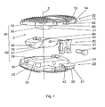
Fig. 1 eine Explosionsdarstellung einer Ausführungsform des erfindungsgemässen Zwischenwirbelimplantates; -
Fig. 2 eine perspektivische Ansicht der inFig. 1 dargestellten Ausführungsform des erfindungsgemässen Zwischenwirbelimplantates in zusammengesetztem Zustand; -
Fig. 3 eine Ansicht von lateral auf eine weitere Ausführungsform des erfindungsgemässen Zwischenwirbelimplantates; und -
Fig. 4 eine perspektivische Ansicht von ventral der Ausführungsform nachFig. 3 . - In den
Fig. 1 und2 ist eine Ausführungsform des erfindungsgemässen Zwischenwirbelimplantates 1 dargestellt, welche ein oberes Teil 10 mit einer oberen, quer zur Zentralachse 2 angeordneten Appositionsfläche 15 zur Anlage an die Grundplatte eines angrenzenden Wirbelkörpers, ein unteres Teil 20 mit einer unteren, quer zur Zentralachse 2 angeordneten Appositionsfläche 25 zur Anlage an die Deckplatte des angrenzenden Wirbelkörpers und zwei Gelenke 38;39 umfasst. Das obere Teil 10 und das untere Teil 20 sind über die Gelenke 38;39 relativ zueinander bewegbar verbunden, wobei die Bewegbarkeit des oberen Teils 10 relativ zum unteren Teil 20 um eine erste, quer zur Zentralachse 2 angeordnete Drehachse 3 innerhalb eines Winkelbereiches von +10° bis -6° eingeschränkt ist und um eine zweite, quer zur Zentralachse 2 und senkrecht zur ersten Drehachse 3 angeordneten Drehachse 4 innerhalb eines Winkelbereiches von ± 7° eingeschränkt ist - Die beiden Gelenke 38;39 sind durch drei Gelenkteile 31;32;33 realisiert, wovon das untere Gelenkteil 33 und das obere Gelenkteil 31 je ein mit dem mittleren Gelenkteil 32 zuammenwirkendes Gelenk 38;39 bilden. Die zwei Gelenke 38;39 weisen je eine Drehachse 3;4 auf, wobei die Drehachsen senkrecht aufeinander und senkrecht zur Zentralachse 2 stehen. Das untere Gelenk 39 umfasst als Artikulationsflächen eine am mittleren Gelenkteil 32 angeordnete zur ersten Drehachse 3 koaxiale, untere konvexe Gleitfläche 57 und eine am unteren Gelenkteil 33 angeordnete, zur Gleitfläche 5 komplementäre, untere konkave Gleitfläche 58. Das obere Gelenk 38 umfasst als Artikulationsflächen eine am oberen Gelenkteil 31 angeordnete zur zweiten Drehachse 4 koaxiale, obere konvexe Gleitfläche 55 und eine am mittleren Gelenkteil 32 angeordnete, zur Gleitfläche 55 komplementäre, untere konkave Gleitfläche 56 zusammen. Die Gleitflächen 55;56;57;58 sind als Teilflächen von Kreiszylindermantelflächen ausgestaltet.
- Ferner sind am oberen und am mittleren Gelenkteil 31;32 axial endständig zu den Drehachsen 3;4 koaxiale Nocken 90 angebracht, welche in Langlochführungen 91 im unteren Gelenkteil und im mittleren Gelenkteil 32 verschiebbar aufgenommen sind. Durch die in den Langlochführungen 91 geführten Nocken 90 werden die Drehwinkel der Gelenkteile 31;32;33 um die Drehachsen 3;4 begrenzt. Zudem wird das Zwischenwirbelimplantat 1 durch die in den Langlochführungen 91 aufgenommenen Nocken 90 zusammengehalten.
- Die Bewegbarkeit der beiden Teile 10;20 relativ zueinander ist durch die Mittel 40 lösbar blockierbar. Die Mittel 40 umfassen in der hier dargestellten Ausführungsform einen von den ventralen Seitenflächen 11;21 der beiden Teile 10;20 her quer zur Zentralachse 2 und parallel zu den lateralen Seitenflächen 13;14;23;24 der beiden Teile 10;20 einschiebbaren Einsatz 41. Das Einschieben des Einsatzes 41 erfolgt in zwei Vertiefungen 42;43, welche als Schwalbenschwanzführungen ausgestaltet sind. Der Einsatz 41 wird von den ventralen Seitenflächen 11;21 der beiden Teile 10;20 in die als Schwalbenschwanzführungen ausgestalteten Vertiefungen 42;43 eingeführt und am unteren Teil 20 mittels einer Schraube 44 befestigt. Zudem ist der Einsatz 41 endständig komplementär zu den Vertiefungen 42;43 ausgestaltet, so dass die beiden Teile 10;20 bei eingeschobenem Einsatz 41 parallel zur Zentralachse 2 relativ zueinander fixiert sind.
- In
Fig. 3 und4 ist eine Ausführungsform des erfindungsgemässen Zwischenwirbelimplantates 1 dargestellt, welche sich von der in denFig. 1 und2 dargestellten Ausführungsform nur darin unterscheidet, dass die beiden Teilen 10;20 Bohrungen 80 zur Aufnahme von Knochenfixationsmitteln 81 umfassen, wobei die Knochenfixationsmittel 80 hier als Knochenschrauben ausgestaltet sind. Die Bohrungen 80 weisen Längsachsen 83 auf, welche einen Winkel γ mit der Zentralachse 2 einschliessen. Ferner durchdringen je zwei Bohrungen 80 eines der beiden Teile 10;20 von der ventralen Seitenfläche 11;21 zur Appositionsfläche 15;25. Die Längsachsen 83 der Bohrungen 80 stehen sowohl von lateral betrachtet (Fig. 3 ) als auch von ventral betrachtet (Fig. 4 ) schräg zur Zentralachse 2. Ferner sind die Bohrungen 80 konisch, sich gegen die Appositionsflächen 15;25 verjüngend ausgestaltet und mit Innengewinden 82 versehen, welche zur schraubbaren Aufnahme der mit komplementären Aussengewinden versehenen Schraubenköpfe 84 der als Knochenschrauben ausgestalteten Knochenfixationsmittel 81 dienen.
Claims (15)
- Zwischenwirbelimplantat (1), insbesondere künstliche Bandscheibe, mit einer Zentralachse (2), einem oberen Teil (10), das für die Anlage an die Grundplatte eines darüber liegenden Wirbelkörpers geeignet ist und einem unteren Teil (20), das für die Anlage an die Deckplatte eines darunter liegenden Wirbelkörpers geeignet ist, wobeiA) das obere Teil (10) eine ventrale Seitenfläche (11), eine dorsale Seitenfläche (12), zwei laterale Seitenflächen (13,14), eine obere Appositionsfläche (15) und eine untere Oberfläche (16) aufweist;B) das untere Teil (20) eine ventrale Seitenfläche (21), eine dorsale Seitenfläche (22), zwei laterale Seitenflächen (23,24), eine untere Appositionsfläche (25) und eine obere Oberfläche (26) aufweist; wobeiC) die beiden Teile (10;20) durch zwei zwischen den beiden Teilen (10;20) angeordnete Gelenke (38;39) relativ zueinander bewegbar sind;D) jedes der Gelenke (38;39) eine Drehachse (3;4) aufweist und die beiden Drehachsen (3;4) quer zueinander angeordnet sind; undE) die beiden Gelenke (38;39) durch ein mit dem oberen Teil (10) verbundenes, oberes Gelenkteil (31), ein mittleres Gelenkteil (32) und ein mit dem unteren Teil (20) verbundenes Gelenkteil (33) realisiert sind;F) eines der aussenstehenden Gelenkteile (31;33) mindestens eine bezüglich einer Drehachse (3;4) rotationssymmetrische, konkave Gleitfläche (58) umfasst;G) das mittlere Gelenkteil (32) mindestens eine zu dieser konkaven Gleitfläche (58) komplementäre, konvexe Gleitfläche (57) umfasst,H) das andere der aussenstehenden Gelenkteile (31;33) mindestens eine bezüglich der anderen Drehachse (3;4) rotationssymmetrische, konvexe Gleitfläche (55) umfasst;I) das mittlere Gelenkteil (32) mindestens eine zu dieser konvexen Gleitfläche (55) komplementäre, konkave Gleitfläche (56) umfasst; undJ) die Gleitflächen (55;56;57;58) als Teilflächen von Kreiszylinder- oder Kreiskegel-Mantelflächen ausgestaltet sind;
dadurch gekennzeichnet, dassK) Mittel (40) vorgesehen sind, welche geeignet sind eine temporäre Blockierung der Beweglichkeit der beiden Teile (10,20) um die Gelenke (38;39) herbeizuführen. - Zwischenwirbelimplantat (1) nach Anspruch 1, dadurch gekennzeichnet, dass das untere Gelenkteil (33) mindestens eine bezüglich der ersten Drehachse (3) rotationssymmetrische, untere konkave Gleitfläche (58) umfasst und das mittlere Gelenkteil (32) mindestens eine zur unteren konkaven Gleitfläche (58) komplementäre, untere konvexe Gleitfläche (57) umfasst.
- Zwischenwirbelimplantat (1) nach Anspruch 1 oder 2, dadurch gekennzeichnet, dass das obere Gelenkteil (31) mindestens eine bezüglich der zweiten Drehachse (4) rotationssymmetrische, obere konvexe Gleitfläche (55) umfasst und das mittlere Gelenkteil (32) mindestens eine zur oberen konvexen Gleitfläche (55) komplementäre, obere konkave Gleitfläche (56) umfasst.
- Zwischenwirbelimplantat (1) nach einem der Ansprüche 1 bis 3, dadurch gekennzeichnet, dass Mittel (40) vorgesehen sind, welche die beiden Teile (10;20), bei ihren ventralen Seitenflächen (11;21) gemessen, auf einer festen Distanz voneinander halten.
- Zwischenwirbelimplantat (1) nach einem der Ansprüche 1 bis 4, dadurch gekennzeichnet, dass die Drehachsen (3;4) windschief zueinander angeordnet sind.
- Zwischenwirbelimplantat (1) nach einem der Ansprüche 1 bis 5, dadurch gekennzeichnet, dass die Mittel (40) an den beiden ventralen Seitenflächen (11,21) an den beiden Teilen (10;20) anbringbar sind.
- Zwischenwirbelimplantat (1) nach einem der Ansprüche 1 bis 6, dadurch gekennzeichnet, dass die Mittel (40) einen Einsatz (41) mit einem unteren Ende (45) und einem oberen Ende (46) und an den beiden Teilen (10;20) je eine Vertiefung (42;43) in den Oberflächen (16;26) umfassen, welche an den ventralen Seitenflächen (11;21) offen sind, und dass der Einsatz (41) mit seinen Enden (45;46) in je eine Vertiefung (42;43) einfügbar ist.
- Zwischenwirbelimplantat (1) nach Anspruch 7, dadurch gekennzeichnet, dass die Vertiefungen (42;43) Schwalbenschwanzführungen sind und die Enden (45;46) am Einsatz (41) komplementär zu diesen Schwalbenschwanzführungen ausgestaltet sind.
- Zwischenwirbelimplantat (1) nach Anspruch 8, dadurch gekennzeichnet, dass sich die Schwalbenschwanzführungen von den ventralen Seitenflächen (11;21) her gegen die dorsalen Seitenflächen (12;22) verjüngen.
- Zwischenwirbelimplantat (1) nach einem der Ansprüche 1 bis 9, dadurch gekennzeichnet, dass das obere und das untere Teil (10;20) je mindestens zwei von den ventralen Seitenflächen (11;21) zu den Appositionsflächen (15;25) durchgehende Bohrungen (80) mit Längsachsen (83) zur Aufnahme von Knochenfixationsmitteln (81) umfassen.
- Zwischenwirbelimplantat (1) nach Anspruch 10, dadurch gekennzeichnet, dass die Längsachsen (83) der Bohrungen (80) mit der Zentralachse (2) einen Winkel γ einschliessen.
- Zwischenwirbelimplantat (1) nach Anspruch 11, dadurch gekennzeichnet, dass der Winkel γ in einem Bereich von 20° und 65° liegt.
- Zwischenwirbelimplantat (1) nach einem der Ansprüche 10 bis 12, dadurch gekennzeichnet, dass die Längsachsen (83) der Bohrungen (80) von den ventralen Seitenflächen (11;21) aus betrachtet von den inneren Oberflächen (16;26) gegen die Appositionsflächen (15;25) divergieren.
- Zwischenwirbelimplantat (1) nach einem der Ansprüche 10 bis 13, dadurch gekennzeichnet, dass sich die Bohrungen (80) gegen die Appositionsflächen (15;25) konisch verjüngen.
- Zwischenwirbelimplantat (1) nach einem der Ansprüche 10 bis 14, dadurch gekennzeichnet, dass die Bohrungen (80) ein Innengewinde (82) aufweisen.
Applications Claiming Priority (1)
| Application Number | Priority Date | Filing Date | Title |
|---|---|---|---|
| PCT/CH2002/000707 WO2004054478A1 (de) | 2002-12-17 | 2002-12-17 | Zwischenwirbelimplantat |
Publications (2)
| Publication Number | Publication Date |
|---|---|
| EP1575457A1 EP1575457A1 (de) | 2005-09-21 |
| EP1575457B1 true EP1575457B1 (de) | 2008-05-07 |
Family
ID=32514200
Family Applications (1)
| Application Number | Title | Priority Date | Filing Date |
|---|---|---|---|
| EP02782618A Expired - Lifetime EP1575457B1 (de) | 2002-12-17 | 2002-12-17 | Zwischenwirbelimplantat |
Country Status (15)
| Country | Link |
|---|---|
| US (1) | US20060122703A1 (de) |
| EP (1) | EP1575457B1 (de) |
| JP (1) | JP2006509563A (de) |
| CN (1) | CN1713866A (de) |
| AR (1) | AR042506A1 (de) |
| AT (1) | ATE394087T1 (de) |
| AU (1) | AU2002347119B2 (de) |
| BR (1) | BR0215964A (de) |
| CA (1) | CA2510246A1 (de) |
| DE (1) | DE50212252D1 (de) |
| ES (1) | ES2306799T3 (de) |
| HU (1) | HUP0500740A2 (de) |
| NZ (1) | NZ540268A (de) |
| TW (1) | TW200418439A (de) |
| WO (1) | WO2004054478A1 (de) |
Families Citing this family (105)
| Publication number | Priority date | Publication date | Assignee | Title |
|---|---|---|---|---|
| FR2897259B1 (fr) | 2006-02-15 | 2008-05-09 | Ldr Medical Soc Par Actions Si | Cage intersomatique transforaminale a greffon de fusion intervetebrale et instrument d'implantation de la cage |
| US7674293B2 (en) | 2004-04-22 | 2010-03-09 | Facet Solutions, Inc. | Crossbar spinal prosthesis having a modular design and related implantation methods |
| US7691145B2 (en) * | 1999-10-22 | 2010-04-06 | Facet Solutions, Inc. | Prostheses, systems and methods for replacement of natural facet joints with artificial facet joint surfaces |
| US20050027361A1 (en) * | 1999-10-22 | 2005-02-03 | Reiley Mark A. | Facet arthroplasty devices and methods |
| US8187303B2 (en) | 2004-04-22 | 2012-05-29 | Gmedelaware 2 Llc | Anti-rotation fixation element for spinal prostheses |
| FR2824261B1 (fr) | 2001-05-04 | 2004-05-28 | Ldr Medical | Prothese de disque intervertebral et procede et outils de mise en place |
| FR2827156B1 (fr) | 2001-07-13 | 2003-11-14 | Ldr Medical | Dispositif de cage vertebrale avec fixation modulaire |
| EP1494751B1 (de) * | 2002-03-30 | 2010-11-10 | Infinity Orthopaedics Company, Ltd. | Medizinische Intervertebrale Vorrichtung |
| US6793678B2 (en) | 2002-06-27 | 2004-09-21 | Depuy Acromed, Inc. | Prosthetic intervertebral motion disc having dampening |
| FR2846550B1 (fr) * | 2002-11-05 | 2006-01-13 | Ldr Medical | Prothese de disque intervertebral |
| CN1774220A (zh) | 2003-02-14 | 2006-05-17 | 德普伊斯派尔公司 | 原位成型的椎间融合器械和方法 |
| US20170020683A1 (en) | 2003-04-21 | 2017-01-26 | Rsb Spine Llc | Bone plate stabilization system and method for its use |
| US7608104B2 (en) | 2003-05-14 | 2009-10-27 | Archus Orthopedics, Inc. | Prostheses, tools and methods for replacement of natural facet joints with artifical facet joint surfaces |
| US20040230304A1 (en) | 2003-05-14 | 2004-11-18 | Archus Orthopedics Inc. | Prostheses, tools and methods for replacement of natural facet joints with artifical facet joint surfaces |
| US20040267367A1 (en) | 2003-06-30 | 2004-12-30 | Depuy Acromed, Inc | Intervertebral implant with conformable endplate |
| US7074238B2 (en) | 2003-07-08 | 2006-07-11 | Archus Orthopedics, Inc. | Prostheses, tools and methods for replacement of natural facet joints with artificial facet joint surfaces |
| ATE435630T1 (de) * | 2003-07-22 | 2009-07-15 | Synthes Gmbh | Zwischenwirbelimplantat mit kalottenartigen gelenkflächen |
| CN100566678C (zh) * | 2003-07-22 | 2009-12-09 | 斯恩蒂斯有限公司 | 带有临时锁定装置的椎间植入物 |
| FR2858546B1 (fr) * | 2003-08-04 | 2006-04-28 | Spine Next Sa | Prothese de disque intervertebral |
| ATE508713T1 (de) | 2003-11-18 | 2011-05-15 | Zimmer Gmbh | Bandscheibenimplantat |
| US20050131406A1 (en) | 2003-12-15 | 2005-06-16 | Archus Orthopedics, Inc. | Polyaxial adjustment of facet joint prostheses |
| RU2354334C2 (ru) | 2004-02-04 | 2009-05-10 | Лдр Медикаль | Протез межпозвоночного диска |
| FR2865629B1 (fr) | 2004-02-04 | 2007-01-26 | Ldr Medical | Prothese de disque intervertebral |
| US8636802B2 (en) | 2004-03-06 | 2014-01-28 | DePuy Synthes Products, LLC | Dynamized interspinal implant |
| US7406775B2 (en) * | 2004-04-22 | 2008-08-05 | Archus Orthopedics, Inc. | Implantable orthopedic device component selection instrument and methods |
| FR2869528B1 (fr) * | 2004-04-28 | 2007-02-02 | Ldr Medical | Prothese de disque intervertebral |
| ES2398085T3 (es) * | 2004-06-30 | 2013-03-13 | Synergy Disc Replacement Inc. | Disco intervertebral artificial |
| EP1781216A2 (de) * | 2004-07-09 | 2007-05-09 | Pioneer Laboratories, Inc. | Skelett-rekonstruktionsvorrichtung |
| AU2005277363A1 (en) | 2004-08-18 | 2006-03-02 | Fsi Acquisition Sub, Llc | Adjacent level facet arthroplasty devices, spine stabilization systems, and methods |
| AU2005307005A1 (en) * | 2004-10-25 | 2006-05-26 | Fsi Acquisition Sub, Llc | Crossbar spinal prosthesis having a modular design and systems for treating spinal pathologies |
| FR2879436B1 (fr) | 2004-12-22 | 2007-03-09 | Ldr Medical | Prothese de disque intervertebral |
| US8496686B2 (en) * | 2005-03-22 | 2013-07-30 | Gmedelaware 2 Llc | Minimally invasive spine restoration systems, devices, methods and kits |
| EP1879529A4 (de) * | 2005-05-02 | 2009-12-16 | Kinetic Spine Technologies Inc | Künstliche bandscheibe |
| FR2887762B1 (fr) | 2005-06-29 | 2007-10-12 | Ldr Medical Soc Par Actions Si | Instrumentation d'insertion de prothese de disque intervertebral entre des vertebres |
| FR2891135B1 (fr) * | 2005-09-23 | 2008-09-12 | Ldr Medical Sarl | Prothese de disque intervertebral |
| FR2893838B1 (fr) | 2005-11-30 | 2008-08-08 | Ldr Medical Soc Par Actions Si | Prothese de disque intervertebral et instrumentation d'insertion de la prothese entre les vertebres |
| WO2007126428A2 (en) | 2005-12-20 | 2007-11-08 | Archus Orthopedics, Inc. | Arthroplasty revision system and method |
| US20070179611A1 (en) * | 2005-12-22 | 2007-08-02 | Dipoto Gene P | Methods and devices for replacement of intervertebral discs |
| WO2008019397A2 (en) | 2006-08-11 | 2008-02-14 | Archus Orthopedics, Inc. | Angled washer polyaxial connection for dynamic spine prosthesis |
| US8906096B2 (en) * | 2006-08-15 | 2014-12-09 | GMFDelaware 2 LLC | Spinal implant |
| US20080119845A1 (en) * | 2006-09-25 | 2008-05-22 | Archus Orthopedics, Inc. | Facet replacement device removal and revision systems and methods |
| US20080140204A1 (en) * | 2006-12-07 | 2008-06-12 | Warsaw Orthopedic, Inc. | Vertebral Implant Systems and Methods of Use |
| WO2008070863A2 (en) | 2006-12-07 | 2008-06-12 | Interventional Spine, Inc. | Intervertebral implant |
| US8715352B2 (en) | 2006-12-14 | 2014-05-06 | Depuy Spine, Inc. | Buckling disc replacement |
| US8465546B2 (en) | 2007-02-16 | 2013-06-18 | Ldr Medical | Intervertebral disc prosthesis insertion assemblies |
| US9358121B2 (en) * | 2007-03-10 | 2016-06-07 | Spinesmith Partners, L.P. | Artificial disc with unique articulating geometry and associated methods |
| US8864832B2 (en) | 2007-06-20 | 2014-10-21 | Hh Spinal Llc | Posterior total joint replacement |
| FR2916956B1 (fr) | 2007-06-08 | 2012-12-14 | Ldr Medical | Cage intersomatique,prothese intervertebrale,dispositif d'ancrage et instrumentation d'implantation |
| KR101498657B1 (ko) * | 2007-06-12 | 2015-03-04 | 키네틱 스파인 테크놀로지스 인크. | 인공 척추간 디스크 |
| US10821003B2 (en) | 2007-06-20 | 2020-11-03 | 3Spline Sezc | Spinal osteotomy |
| US8900307B2 (en) | 2007-06-26 | 2014-12-02 | DePuy Synthes Products, LLC | Highly lordosed fusion cage |
| CN101909549B (zh) * | 2007-10-25 | 2014-07-23 | 奈尔·杜加尔 | 用于置换椎盘的系统和方法 |
| CN101909548B (zh) | 2008-01-17 | 2014-07-30 | 斯恩蒂斯有限公司 | 可膨胀椎间植入件以及制造它的相关方法 |
| US20090248161A1 (en) * | 2008-03-20 | 2009-10-01 | K2M, Inc. | Artificial disc replacement device |
| JP5441997B2 (ja) | 2008-04-05 | 2014-03-12 | ジンテス ゲゼルシャフト ミット ベシュレンクテル ハフツング | 拡張可能な椎骨間インプラント |
| PL2992860T3 (pl) * | 2009-02-25 | 2017-10-31 | Spinewelding Ag | Urządzenie do stabilizacji kręgosłupa |
| US9526620B2 (en) | 2009-03-30 | 2016-12-27 | DePuy Synthes Products, Inc. | Zero profile spinal fusion cage |
| US9084688B2 (en) * | 2009-05-19 | 2015-07-21 | DePuy Synthes Products, Inc. | Dynamic trial implants |
| CN101559003B (zh) | 2009-06-02 | 2011-07-20 | 北京纳通投资有限公司 | 人工椎间盘 |
| GB2471133A (en) * | 2009-06-19 | 2010-12-22 | Karin Buettner-Janz | Intervertebral disc prosthesis with modular construction |
| BRPI1014714B1 (pt) | 2009-07-06 | 2020-05-19 | Synthes Gmbh | conjunto de fixação óssea expansível |
| US8403988B2 (en) | 2009-09-11 | 2013-03-26 | Depuy Spine, Inc. | Minimally invasive intervertebral staple distraction devices |
| US9615933B2 (en) | 2009-09-15 | 2017-04-11 | DePuy Synthes Products, Inc. | Expandable ring intervertebral fusion device |
| KR101805935B1 (ko) | 2009-09-17 | 2017-12-06 | 엘디알 홀딩 코포레이션 | 연장가능 골 고정 부재를 구비한 추간 임플란트 |
| US8840668B1 (en) | 2009-11-11 | 2014-09-23 | Nuvasive, Inc. | Spinal implants, instruments and related methods |
| US8740983B1 (en) | 2009-11-11 | 2014-06-03 | Nuvasive, Inc. | Spinal fusion implants and related methods |
| US9393129B2 (en) | 2009-12-10 | 2016-07-19 | DePuy Synthes Products, Inc. | Bellows-like expandable interbody fusion cage |
| JP5647264B2 (ja) | 2009-12-31 | 2014-12-24 | エル・デ・エール・メデイカル | 固定装置、椎間インプラント、および移植器具 |
| CA2793185C (en) | 2010-03-16 | 2019-02-12 | Pinnacle Spine Group, Llc | Intervertebral implants and graft delivery systems and methods |
| US9282979B2 (en) | 2010-06-24 | 2016-03-15 | DePuy Synthes Products, Inc. | Instruments and methods for non-parallel disc space preparation |
| US8979860B2 (en) | 2010-06-24 | 2015-03-17 | DePuy Synthes Products. LLC | Enhanced cage insertion device |
| WO2012003175A1 (en) | 2010-06-29 | 2012-01-05 | Synthes Usa, Llc | Distractible intervertebral implant |
| US20120078372A1 (en) | 2010-09-23 | 2012-03-29 | Thomas Gamache | Novel implant inserter having a laterally-extending dovetail engagement feature |
| US9402732B2 (en) | 2010-10-11 | 2016-08-02 | DePuy Synthes Products, Inc. | Expandable interspinous process spacer implant |
| DE112012000567B4 (de) * | 2011-01-25 | 2019-01-24 | Nuvasive, Inc. | Wirbelsäulenimplantate zur drehbaren Wirbelanpassung |
| AU2012301640B2 (en) * | 2011-09-01 | 2017-03-16 | In Queue Innovations, Llc | Disc replacement device and method of use |
| US9248028B2 (en) | 2011-09-16 | 2016-02-02 | DePuy Synthes Products, Inc. | Removable, bone-securing cover plate for intervertebral fusion cage |
| US9380932B1 (en) | 2011-11-02 | 2016-07-05 | Pinnacle Spine Group, Llc | Retractor devices for minimally invasive access to the spine |
| FR2987256B1 (fr) | 2012-02-24 | 2014-08-08 | Ldr Medical | Dispositif d'ancrage pour implant intervertebral, implant intervertebral et instrumentation d'implantation |
| US8940052B2 (en) | 2012-07-26 | 2015-01-27 | DePuy Synthes Products, LLC | Expandable implant |
| US9717601B2 (en) | 2013-02-28 | 2017-08-01 | DePuy Synthes Products, Inc. | Expandable intervertebral implant, system, kit and method |
| US9522070B2 (en) | 2013-03-07 | 2016-12-20 | Interventional Spine, Inc. | Intervertebral implant |
| WO2014159739A1 (en) | 2013-03-14 | 2014-10-02 | Pinnacle Spine Group, Llc | Interbody implants and graft delivery systems |
| FR3005569B1 (fr) | 2013-05-16 | 2021-09-03 | Ldr Medical | Implant vertebral, dispositif de fixation vertebrale d'implant et instrumentation d'implantation |
| USD745159S1 (en) | 2013-10-10 | 2015-12-08 | Nuvasive, Inc. | Intervertebral implant |
| FR3016793B1 (fr) | 2014-01-30 | 2021-05-07 | Ldr Medical | Dispositif d'ancrage pour implant spinal, implant spinal et instrumentation d'implantation |
| CN104970905B (zh) * | 2014-04-02 | 2018-02-23 | 宝楠生技股份有限公司 | 具立体网格体的脊椎小面关节融合固定器 |
| FR3020756B1 (fr) | 2014-05-06 | 2022-03-11 | Ldr Medical | Implant vertebral, dispositif de fixation vertebrale d'implant et instrumentation d'implantation |
| USD858769S1 (en) | 2014-11-20 | 2019-09-03 | Nuvasive, Inc. | Intervertebral implant |
| US11426290B2 (en) | 2015-03-06 | 2022-08-30 | DePuy Synthes Products, Inc. | Expandable intervertebral implant, system, kit and method |
| US9913727B2 (en) | 2015-07-02 | 2018-03-13 | Medos International Sarl | Expandable implant |
| US11510788B2 (en) | 2016-06-28 | 2022-11-29 | Eit Emerging Implant Technologies Gmbh | Expandable, angularly adjustable intervertebral cages |
| WO2018002715A2 (en) | 2016-06-28 | 2018-01-04 | Eit Emerging Implant Technologies Gmbh | Expandable and angularly adjustable articulating intervertebral cages |
| US10537436B2 (en) | 2016-11-01 | 2020-01-21 | DePuy Synthes Products, Inc. | Curved expandable cage |
| US10888433B2 (en) | 2016-12-14 | 2021-01-12 | DePuy Synthes Products, Inc. | Intervertebral implant inserter and related methods |
| US10398563B2 (en) | 2017-05-08 | 2019-09-03 | Medos International Sarl | Expandable cage |
| US11344424B2 (en) | 2017-06-14 | 2022-05-31 | Medos International Sarl | Expandable intervertebral implant and related methods |
| US10940016B2 (en) | 2017-07-05 | 2021-03-09 | Medos International Sarl | Expandable intervertebral fusion cage |
| CN107693169A (zh) * | 2017-09-16 | 2018-02-16 | 武汉光谷北宸医疗器械有限公司 | 楔入式可调节人工椎体 |
| US11446156B2 (en) | 2018-10-25 | 2022-09-20 | Medos International Sarl | Expandable intervertebral implant, inserter instrument, and related methods |
| US11622864B2 (en) | 2019-06-28 | 2023-04-11 | Innovasis, Inc. | Expandable intervertebral implant |
| US11426286B2 (en) | 2020-03-06 | 2022-08-30 | Eit Emerging Implant Technologies Gmbh | Expandable intervertebral implant |
| US11850160B2 (en) | 2021-03-26 | 2023-12-26 | Medos International Sarl | Expandable lordotic intervertebral fusion cage |
| US11752009B2 (en) | 2021-04-06 | 2023-09-12 | Medos International Sarl | Expandable intervertebral fusion cage |
| TWI819656B (zh) * | 2022-06-14 | 2023-10-21 | 緒鎮軟體科技股份有限公司 | 人工椎間盤 |
Family Cites Families (7)
| Publication number | Priority date | Publication date | Assignee | Title |
|---|---|---|---|---|
| ATE44871T1 (de) * | 1984-09-04 | 1989-08-15 | Univ Berlin Humboldt | Bandscheibenendoprothese. |
| DE4208115A1 (de) * | 1992-03-13 | 1993-09-16 | Link Waldemar Gmbh Co | Bandscheibenendoprothese |
| CA2394304C (en) * | 2000-02-04 | 2008-12-16 | Gary Karlin Michelson | Expandable push-in interbody spinal fusion implant |
| US6500205B1 (en) * | 2000-04-19 | 2002-12-31 | Gary K. Michelson | Expandable threaded arcuate interbody spinal fusion implant with cylindrical configuration during insertion |
| US6849093B2 (en) * | 2001-03-09 | 2005-02-01 | Gary K. Michelson | Expansion constraining member adapted for use with an expandable interbody spinal fusion implant and method for use thereof |
| FR2824261B1 (fr) * | 2001-05-04 | 2004-05-28 | Ldr Medical | Prothese de disque intervertebral et procede et outils de mise en place |
| US6793678B2 (en) * | 2002-06-27 | 2004-09-21 | Depuy Acromed, Inc. | Prosthetic intervertebral motion disc having dampening |
-
2002
- 2002-12-17 NZ NZ540268A patent/NZ540268A/en not_active IP Right Cessation
- 2002-12-17 JP JP2004559546A patent/JP2006509563A/ja not_active Ceased
- 2002-12-17 HU HU0500740A patent/HUP0500740A2/hu unknown
- 2002-12-17 EP EP02782618A patent/EP1575457B1/de not_active Expired - Lifetime
- 2002-12-17 CA CA002510246A patent/CA2510246A1/en not_active Abandoned
- 2002-12-17 WO PCT/CH2002/000707 patent/WO2004054478A1/de active IP Right Grant
- 2002-12-17 DE DE50212252T patent/DE50212252D1/de not_active Expired - Lifetime
- 2002-12-17 ES ES02782618T patent/ES2306799T3/es not_active Expired - Lifetime
- 2002-12-17 CN CNA028300602A patent/CN1713866A/zh active Pending
- 2002-12-17 US US10/538,950 patent/US20060122703A1/en not_active Abandoned
- 2002-12-17 BR BR0215964-3A patent/BR0215964A/pt not_active IP Right Cessation
- 2002-12-17 AT AT02782618T patent/ATE394087T1/de not_active IP Right Cessation
- 2002-12-17 AU AU2002347119A patent/AU2002347119B2/en not_active Ceased
-
2003
- 2003-11-28 TW TW092133518A patent/TW200418439A/zh unknown
- 2003-12-17 AR ARP030104678A patent/AR042506A1/es unknown
Also Published As
| Publication number | Publication date |
|---|---|
| WO2004054478A1 (de) | 2004-07-01 |
| ES2306799T3 (es) | 2008-11-16 |
| AU2002347119A1 (en) | 2004-07-09 |
| AU2002347119B2 (en) | 2007-01-25 |
| ATE394087T1 (de) | 2008-05-15 |
| NZ540268A (en) | 2006-07-28 |
| BR0215964A (pt) | 2005-09-27 |
| CA2510246A1 (en) | 2004-07-01 |
| TW200418439A (en) | 2004-10-01 |
| DE50212252D1 (de) | 2008-06-19 |
| HUP0500740A2 (en) | 2006-04-28 |
| JP2006509563A (ja) | 2006-03-23 |
| US20060122703A1 (en) | 2006-06-08 |
| EP1575457A1 (de) | 2005-09-21 |
| CN1713866A (zh) | 2005-12-28 |
| AR042506A1 (es) | 2005-06-22 |
Similar Documents
| Publication | Publication Date | Title |
|---|---|---|
| EP1575457B1 (de) | Zwischenwirbelimplantat | |
| EP1572037B1 (de) | Zwischenwirbelimplantat mit kippbaren gelenkteilen | |
| EP1572038B1 (de) | Zwischenwirbelimplantat mit kardanisch gelagerten gelenkteilen | |
| EP1572036B1 (de) | Zwischenwirbelimplantat mit auf wälzkörpern gelagerten gelenkteilen | |
| EP1572039B1 (de) | Zwischenwirbelimplantat | |
| EP1539051B1 (de) | Implantat mit zweiteiligem gelenk | |
| EP1646336B1 (de) | Zwischenwirbelimplantat mit kalottenartigen gelenkflächen | |
| EP1872748B1 (de) | Implantat zum Einsetzen zwischen zwei Wirbelkörper der Wirbelsäule | |
| EP1648351B1 (de) | Zwischenwirbelimplantat mit temporären blockiermitteln | |
| DE69936263T2 (de) | Geschraubte zylindrische, multidiskoide einfach- oder mehrfach-netzwerkplattenprothese | |
| EP0942692B1 (de) | Femorales teil einer kniegelenkprothese | |
| EP0079441B1 (de) | Endoprothese zum Ersatz stabförmiger Knochen | |
| EP0680292B1 (de) | System für die ausbildung einer kniegelenk-endoprothese | |
| EP1848379A1 (de) | Zwischenwirbelimplantat | |
| DE202005019487U1 (de) | Facettengelenkprothese | |
| DE2908898A1 (de) | Prothesengelenk | |
| DE10323363A1 (de) | Implantat zum Einsetzen zwischen Wirbelkörper der Wirbelsäule | |
| EP1417940A1 (de) | Wirbelsäulenprothese | |
| DE202004015198U1 (de) | Implantatsystem | |
| EP1411870A1 (de) | Endoprothese für ein kniegelenk | |
| DE102004047566B3 (de) | Implantatsystem | |
| DE102015101675B4 (de) | Implantat | |
| DE202007004508U1 (de) | Modularer Implantatteil und Kniegelenkprothese | |
| DE4425529A1 (de) | System für die Ausbildung einer Kniegelenk-Endoprothese |
Legal Events
| Date | Code | Title | Description |
|---|---|---|---|
| PUAI | Public reference made under article 153(3) epc to a published international application that has entered the european phase |
Free format text: ORIGINAL CODE: 0009012 |
|
| 17P | Request for examination filed |
Effective date: 20050510 |
|
| AK | Designated contracting states |
Kind code of ref document: A1 Designated state(s): AT BE BG CH CY CZ DE DK EE ES FI FR GB GR IE IT LI LU MC NL PT SE SI SK TR |
|
| AX | Request for extension of the european patent |
Extension state: AL LT LV MK RO |
|
| RAP1 | Party data changed (applicant data changed or rights of an application transferred) |
Owner name: SYNTHES GMBH |
|
| RAP1 | Party data changed (applicant data changed or rights of an application transferred) |
Owner name: SYNTHES GMBH |
|
| DAX | Request for extension of the european patent (deleted) | ||
| 17Q | First examination report despatched |
Effective date: 20070403 |
|
| GRAP | Despatch of communication of intention to grant a patent |
Free format text: ORIGINAL CODE: EPIDOSNIGR1 |
|
| GRAS | Grant fee paid |
Free format text: ORIGINAL CODE: EPIDOSNIGR3 |
|
| GRAA | (expected) grant |
Free format text: ORIGINAL CODE: 0009210 |
|
| AK | Designated contracting states |
Kind code of ref document: B1 Designated state(s): AT BE BG CH CY CZ DE DK EE ES FI FR GB GR IE IT LI LU MC NL PT SE SI SK TR |
|
| REG | Reference to a national code |
Ref country code: GB Ref legal event code: FG4D Free format text: NOT ENGLISH |
|
| REG | Reference to a national code |
Ref country code: CH Ref legal event code: NV Representative=s name: DR. LUSUARDI AG Ref country code: CH Ref legal event code: EP |
|
| REG | Reference to a national code |
Ref country code: IE Ref legal event code: FG4D Free format text: LANGUAGE OF EP DOCUMENT: GERMAN |
|
| REF | Corresponds to: |
Ref document number: 50212252 Country of ref document: DE Date of ref document: 20080619 Kind code of ref document: P |
|
| REG | Reference to a national code |
Ref country code: SE Ref legal event code: TRGR |
|
| PG25 | Lapsed in a contracting state [announced via postgrant information from national office to epo] |
Ref country code: SI Free format text: LAPSE BECAUSE OF FAILURE TO SUBMIT A TRANSLATION OF THE DESCRIPTION OR TO PAY THE FEE WITHIN THE PRESCRIBED TIME-LIMIT Effective date: 20080507 |
|
| PG25 | Lapsed in a contracting state [announced via postgrant information from national office to epo] |
Ref country code: FI Free format text: LAPSE BECAUSE OF FAILURE TO SUBMIT A TRANSLATION OF THE DESCRIPTION OR TO PAY THE FEE WITHIN THE PRESCRIBED TIME-LIMIT Effective date: 20080507 Ref country code: NL Free format text: LAPSE BECAUSE OF FAILURE TO SUBMIT A TRANSLATION OF THE DESCRIPTION OR TO PAY THE FEE WITHIN THE PRESCRIBED TIME-LIMIT Effective date: 20080507 |
|
| NLV1 | Nl: lapsed or annulled due to failure to fulfill the requirements of art. 29p and 29m of the patents act | ||
| REG | Reference to a national code |
Ref country code: ES Ref legal event code: FG2A Ref document number: 2306799 Country of ref document: ES Kind code of ref document: T3 |
|
| REG | Reference to a national code |
Ref country code: IE Ref legal event code: FD4D |
|
| PG25 | Lapsed in a contracting state [announced via postgrant information from national office to epo] |
Ref country code: IE Free format text: LAPSE BECAUSE OF FAILURE TO SUBMIT A TRANSLATION OF THE DESCRIPTION OR TO PAY THE FEE WITHIN THE PRESCRIBED TIME-LIMIT Effective date: 20080507 Ref country code: DK Free format text: LAPSE BECAUSE OF FAILURE TO SUBMIT A TRANSLATION OF THE DESCRIPTION OR TO PAY THE FEE WITHIN THE PRESCRIBED TIME-LIMIT Effective date: 20080507 Ref country code: CZ Free format text: LAPSE BECAUSE OF FAILURE TO SUBMIT A TRANSLATION OF THE DESCRIPTION OR TO PAY THE FEE WITHIN THE PRESCRIBED TIME-LIMIT Effective date: 20080507 Ref country code: PT Free format text: LAPSE BECAUSE OF FAILURE TO SUBMIT A TRANSLATION OF THE DESCRIPTION OR TO PAY THE FEE WITHIN THE PRESCRIBED TIME-LIMIT Effective date: 20081007 |
|
| PG25 | Lapsed in a contracting state [announced via postgrant information from national office to epo] |
Ref country code: SK Free format text: LAPSE BECAUSE OF FAILURE TO SUBMIT A TRANSLATION OF THE DESCRIPTION OR TO PAY THE FEE WITHIN THE PRESCRIBED TIME-LIMIT Effective date: 20080507 |
|
| PLBE | No opposition filed within time limit |
Free format text: ORIGINAL CODE: 0009261 |
|
| STAA | Information on the status of an ep patent application or granted ep patent |
Free format text: STATUS: NO OPPOSITION FILED WITHIN TIME LIMIT |
|
| 26N | No opposition filed |
Effective date: 20090210 |
|
| PG25 | Lapsed in a contracting state [announced via postgrant information from national office to epo] |
Ref country code: BG Free format text: LAPSE BECAUSE OF FAILURE TO SUBMIT A TRANSLATION OF THE DESCRIPTION OR TO PAY THE FEE WITHIN THE PRESCRIBED TIME-LIMIT Effective date: 20080807 Ref country code: EE Free format text: LAPSE BECAUSE OF FAILURE TO SUBMIT A TRANSLATION OF THE DESCRIPTION OR TO PAY THE FEE WITHIN THE PRESCRIBED TIME-LIMIT Effective date: 20080507 |
|
| BERE | Be: lapsed |
Owner name: SYNTHES GMBH Effective date: 20081231 |
|
| PG25 | Lapsed in a contracting state [announced via postgrant information from national office to epo] |
Ref country code: MC Free format text: LAPSE BECAUSE OF NON-PAYMENT OF DUE FEES Effective date: 20081231 |
|
| PG25 | Lapsed in a contracting state [announced via postgrant information from national office to epo] |
Ref country code: BE Free format text: LAPSE BECAUSE OF NON-PAYMENT OF DUE FEES Effective date: 20081231 |
|
| PGFP | Annual fee paid to national office [announced via postgrant information from national office to epo] |
Ref country code: AT Payment date: 20091211 Year of fee payment: 8 Ref country code: SE Payment date: 20091207 Year of fee payment: 8 |
|
| PGFP | Annual fee paid to national office [announced via postgrant information from national office to epo] |
Ref country code: ES Payment date: 20100113 Year of fee payment: 8 |
|
| PG25 | Lapsed in a contracting state [announced via postgrant information from national office to epo] |
Ref country code: CY Free format text: LAPSE BECAUSE OF FAILURE TO SUBMIT A TRANSLATION OF THE DESCRIPTION OR TO PAY THE FEE WITHIN THE PRESCRIBED TIME-LIMIT Effective date: 20080507 Ref country code: LU Free format text: LAPSE BECAUSE OF NON-PAYMENT OF DUE FEES Effective date: 20081217 |
|
| PG25 | Lapsed in a contracting state [announced via postgrant information from national office to epo] |
Ref country code: TR Free format text: LAPSE BECAUSE OF FAILURE TO SUBMIT A TRANSLATION OF THE DESCRIPTION OR TO PAY THE FEE WITHIN THE PRESCRIBED TIME-LIMIT Effective date: 20080507 |
|
| PG25 | Lapsed in a contracting state [announced via postgrant information from national office to epo] |
Ref country code: GR Free format text: LAPSE BECAUSE OF FAILURE TO SUBMIT A TRANSLATION OF THE DESCRIPTION OR TO PAY THE FEE WITHIN THE PRESCRIBED TIME-LIMIT Effective date: 20080808 |
|
| PG25 | Lapsed in a contracting state [announced via postgrant information from national office to epo] |
Ref country code: AT Free format text: LAPSE BECAUSE OF NON-PAYMENT OF DUE FEES Effective date: 20101217 |
|
| REG | Reference to a national code |
Ref country code: SE Ref legal event code: EUG |
|
| PG25 | Lapsed in a contracting state [announced via postgrant information from national office to epo] |
Ref country code: SE Free format text: LAPSE BECAUSE OF NON-PAYMENT OF DUE FEES Effective date: 20101218 |
|
| REG | Reference to a national code |
Ref country code: ES Ref legal event code: FD2A Effective date: 20120206 |
|
| PG25 | Lapsed in a contracting state [announced via postgrant information from national office to epo] |
Ref country code: ES Free format text: LAPSE BECAUSE OF NON-PAYMENT OF DUE FEES Effective date: 20101218 |
|
| REG | Reference to a national code |
Ref country code: FR Ref legal event code: PLFP Year of fee payment: 15 |
|
| REG | Reference to a national code |
Ref country code: FR Ref legal event code: PLFP Year of fee payment: 16 |
|
| PGFP | Annual fee paid to national office [announced via postgrant information from national office to epo] |
Ref country code: DE Payment date: 20181204 Year of fee payment: 17 |
|
| PGFP | Annual fee paid to national office [announced via postgrant information from national office to epo] |
Ref country code: FR Payment date: 20181121 Year of fee payment: 17 Ref country code: CH Payment date: 20181217 Year of fee payment: 17 Ref country code: GB Payment date: 20181212 Year of fee payment: 17 |
|
| PGFP | Annual fee paid to national office [announced via postgrant information from national office to epo] |
Ref country code: IT Payment date: 20181220 Year of fee payment: 17 |
|
| REG | Reference to a national code |
Ref country code: DE Ref legal event code: R119 Ref document number: 50212252 Country of ref document: DE |
|
| REG | Reference to a national code |
Ref country code: CH Ref legal event code: PL |
|
| GBPC | Gb: european patent ceased through non-payment of renewal fee |
Effective date: 20191217 |
|
| PG25 | Lapsed in a contracting state [announced via postgrant information from national office to epo] |
Ref country code: IT Free format text: LAPSE BECAUSE OF NON-PAYMENT OF DUE FEES Effective date: 20191217 Ref country code: DE Free format text: LAPSE BECAUSE OF NON-PAYMENT OF DUE FEES Effective date: 20200701 Ref country code: FR Free format text: LAPSE BECAUSE OF NON-PAYMENT OF DUE FEES Effective date: 20191231 Ref country code: GB Free format text: LAPSE BECAUSE OF NON-PAYMENT OF DUE FEES Effective date: 20191217 |
|
| PG25 | Lapsed in a contracting state [announced via postgrant information from national office to epo] |
Ref country code: LI Free format text: LAPSE BECAUSE OF NON-PAYMENT OF DUE FEES Effective date: 20191231 Ref country code: CH Free format text: LAPSE BECAUSE OF NON-PAYMENT OF DUE FEES Effective date: 20191231 |