EP1575191A1 - Method for data transmission and device for such a method - Google Patents
Method for data transmission and device for such a method Download PDFInfo
- Publication number
- EP1575191A1 EP1575191A1 EP05290461A EP05290461A EP1575191A1 EP 1575191 A1 EP1575191 A1 EP 1575191A1 EP 05290461 A EP05290461 A EP 05290461A EP 05290461 A EP05290461 A EP 05290461A EP 1575191 A1 EP1575191 A1 EP 1575191A1
- Authority
- EP
- European Patent Office
- Prior art keywords
- data transmission
- vehicle
- transmission device
- optical
- transparent wall
- Prior art date
- Legal status (The legal status is an assumption and is not a legal conclusion. Google has not performed a legal analysis and makes no representation as to the accuracy of the status listed.)
- Withdrawn
Links
Images


Classifications
-
- H—ELECTRICITY
- H04—ELECTRIC COMMUNICATION TECHNIQUE
- H04B—TRANSMISSION
- H04B10/00—Transmission systems employing electromagnetic waves other than radio-waves, e.g. infrared, visible or ultraviolet light, or employing corpuscular radiation, e.g. quantum communication
- H04B10/80—Optical aspects relating to the use of optical transmission for specific applications, not provided for in groups H04B10/03 - H04B10/70, e.g. optical power feeding or optical transmission through water
- H04B10/801—Optical aspects relating to the use of optical transmission for specific applications, not provided for in groups H04B10/03 - H04B10/70, e.g. optical power feeding or optical transmission through water using optical interconnects, e.g. light coupled isolators, circuit board interconnections
Definitions
- the technical field of the invention is that of methods for transmitting data.
- Vehicles and in particular land vehicles sometimes include ancillary devices that are attached to the outside of the vehicle and that it is necessary to be able to control from inside the vehicle.
- the patents FR2701105 and FR2750204 thus describe demining devices comprising one or more coils generating a variable electromagnetic field.
- These coils are connected to an electronic box which provides them with a modulated power signal depending on the shape of the desired field to ensure clearance.
- the electronic box connected to the coils must be able to be controlled remotely by an operator located inside of the vehicle. It is therefore necessary to provide a line of transmission of data between an electronic box of control located inside the vehicle and the housing controlled associated with the coils and which is attached to the outside.
- This line will at least ensure the orders on / off the demining medium and it will ensure the most often the exchange of control signals and / or test the state of the demining means as well as possibly the transmission of programming signals.
- EP1004844 discloses a device for active defense using load barriers formed.
- the method and the device according to the invention enable the transmission of data between a internal housing to a vehicle and an external housing to this vehicle without the need to drill through the vehicle wall.
- the subject of the invention is a transmission method data between an electronic control unit arranged inside a vehicle and an electronic unit controlled disposed outside the vehicle, characterized in that the data is transmitted between two housings in the form of light signals through at least one transparent wall.
- the light signals can be coded.
- the light signals can also be emitted in a frequency band located outside the visible spectrum.
- the subject of the invention is also a device for data transmission implementing such a method, device characterized in that it comprises at least one first optical transceiver means connected to the housing control electronics and arranged inside the vehicle and at least one second optical transceiver means connected to the electronic control unit and arranged to outside the vehicle, the first and second means optical transceivers being arranged relative to each other to each other so that they can exchange their signals at through at least one transparent wall.
- the first and second transmitter / receiver means optics can be arranged directly opposite one of the other side and other of at least one transparent wall.
- first and second means optical transmitters / receivers may be arranged indirectly facing each other, on both sides an episcope with at least two surfaces reflective.
- At least one transmitter / receiver means optics can be placed at a distance from the wall transparent and will be connected to it by a fiber optic that will be attached to the transparent wall by means support.
- At least one optical transceiver means may be integral with its electronic housing or integrated with it.
- Means for encoding and decoding the signals be provided in each electronic control unit in upstream of the optical transmitter / receiver means.
- the support means may comprise a plate attached to the wall and a connector for sealing the plate to the fiber.
- At least one support means may comprise a means of adjustment of the positioning of the end of the optical fiber relative to the plate.
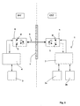
- FIG. 1 shows schematically an appendix 1 attached to the outside (EXT) of a vehicle (not shown).
- This an additional device 1 comprises two members 2a, 2b connected to an electronic housing 3 which controls their operation.
- the ancillary device may be for example a demining device comprising two coils 2a and 2b.
- the ancillary device could be a device for active defense comprising two response modules 2a, 2b.
- This ancillary device must be able to be ordered and controlled from inside the vehicle (INT).
- control another electronic housing 4 (called control) is arranged inside the vehicle.
- the control box 4 is optionally connected to a control device 5, also internal to the vehicle, by example to an on-board computer or to a driving shot (in the case of the riposte module command).
- the electronic housing external 3 (called controlled box) can exchange data with the electronic control unit 4.
- Data transmission is in the form of light signals 6 through at least one wall transparent 7.
- the transmission device comprises a first transmitter / receiver means 8, connected to the electronic control unit 4, and which is disposed inside (INT) of the vehicle.
- the device also includes a second means optical transceiver 9 connected to the electronic housing ordered 3, and which is arranged outside (EXT) of the vehicle.
- EXT outside
- the optical transceiver means are conventional and well known to those skilled in the art. These means comprise generally a transmitting diode D and a phototransistor T. receiver
- the first 8 and second 9 optical transceivers are arranged one for each to each other so that they can exchange their signals through the transparent wall 7.
- the transparent wall 7 is an element of the vehicle of which the invention simply takes advantage.
- Transparent walls such as windows or windshields are present on all the vehicles to allow the crew to see to outside.
- the light signals used will be coded.
- Another advantage of the transmission device according to the invention is that it does not cause disturbances electromagnetic. Moreover the electric power necessary for its operation is reduced and the emission optical radiates little outside the necessary action area. If several vehicles are located close to each other others, so there is no interaction between different transmission devices according to the invention.
- the device will be defined in such a way that the light signals are emitted in a band of frequency outside the visible spectrum (length wavelength from 0.4 micrometers to 0.7 micrometers).
- An optical communication channel presents a great bandwidth (of the order of a few mega bits per second). It is therefore possible with the device according to the invention to transmit many analog signals or digital.
- Figure 3 thus shows in block diagram form the architecture of an electronics associated with the device according to the invention.
- the control box 4 contains means 10 ensuring the coding of signals 11 to be transmitted to the controlled housing external 3.
- These coding means are connected to the transmission channel E of the first optical transmitter / receiver means 8.
- the control box 4 also contains means 12 decoding the optical signal received by the first average transmitter / receiver 8 (reception channel R). These means decoding are coupled to detection means and error correction 13. Decoded and corrected signals received 14 are then transmitted to processing means (not shown)
- the coding means 10, decoding 12 and error detection / correction 13 will be carried out under the form of algorithms introduced into the memory of a microphone processor.
- the latter can advantageously be incorporated the on-board computer or another computer associated with the shooting conduct.
- Such coding and decoding means are in the field of data transmission.
- the box ordered 3 will contain (preferably in the form of put algorithms in memory in a micro processor) means 15 of coding of signals 16 to be transmitted to the internal control box 4, as well as means 17 for decoding the received optical signal by the second transmitter / receiver means 9.
- the decoding means 17 will be coupled to means for error detection and correction 18 and decoded signals and corrected receipts 19 will then be transmitted to treatment (not shown).
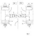
- Figure 2 shows a device according to another mode of embodiment of the invention.
- This device differs from that shown in Figure 1 in that the optical transceiver means 8 and 9 do not are more directly disposed towards each other than both sides of a transparent wall but are arranged indirectly facing each other, on both sides of an episcope 20.
- the episcope 20 is represented here schematically and its dimensions and proportions do not correspond of course not to those of a real episcope.
- Episcopes used in armored vehicles observe the outside of the vehicle following a actual viewing direction that is parallel to the direction of apparent observation of the gaze of the observer.
- an episcope 20 thus comprises two walls transparent 7a and 7b and two reflecting surfaces 21a and 21b.
- a light ray R1 emitted by the first means optical transceiver 8 is reflected on the surface 21a and returned according to R3.
- the radius R3 is reflected on the surface 21b and he comes out of the episcope 20 in one direction parallel to that of radius R1 (radius R2).
- the transmission device according to the invention is perfectly well adapted to a transmission through a episcope Signals are transmitted along paths optics perfectly controlled and which do not lead to loss of light power, so no loss of signal.
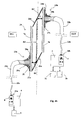
- the transmitter / receiver distance may seek to arrange the transmitter / receiver distance from the transparent wall (s) 7.
- FIG. 4a thus shows a similar embodiment to that of Figure 1, ie in which there is only one transparent wall 7 to cross with a signal luminous.
- Each transmitter / receiver 8 or 9 is thus connected to the wall 7 by an optical fiber 22a, 22b of which one end is fixed to the transparent wall 7 by a support means 23a, 23b.
- optical fibers 22a, 22b are connected to the associated transmitter / receiver means 8 or 9 by a connector 24a, 24b.
- optical fibers 22a, 22b arranged in the vicinity of the wall transparent 7.
- the optical fibers have a diameter of order of 0.5 mm with their external protective sheath 25 which surrounds a heart 26 of about 0.1mm in diameter. They occupy virtually no space at the level of the transparent wall 7 and do not interfere with normal vision at through the wall.
- each optical transceiver means 8 and 9 can then be integrated into its electronic housing 3 or 4.
- the embodiment of the device is thus simplified. All electronic components are integrated into the housings from which only optical fibers 22a, 22b to ensure the transmission of data. Fibers optics are space-saving and insensitive to electromagnetic radiation.
- Each support means 23a and 23b comprises a plate 27a, 27b which is fixed to the wall 7 by an adhesive layer 28a, 28b.
- the support means 23b comprises a connector 29b which allows the optical fiber to be tightly bonded to the plate 27b.
- the support means 23a also has a connector 29a ensuring a tight connection with the plate 27a.
- the support means thus make it possible to make the transmission of information. Indeed the portion of the wall transparent 7 which lies between the ends of the fibers 22a, 22b is then protected against moisture and dirt that is no longer likely to disturb the passage of optical signals from one fiber to another.
- This positioning can be achieved during the collage in implementing means for verifying the passage signals from one fiber to another.
- At the level of means support at least one means allowing a fine adjustment of the position of one optical fiber with respect to the other.
- FIG. 4a shows, at the level of the medium support 23a, an intermediate plate 30 which is fixed in an adjustable manner with respect to the glued plate 27a.
- the connector 29a is fixed to the intermediate plate 30.
- This intermediate plate must be able to be moved by relative to the plate 27a in at least two directions perpendicular to each other and parallel to the wall transparent. 7.
- the range of displacements to be provided for the plate 30 is reduced (less than the mm following the two perpendicular directions).
- the setting will be made in a simple way, for example by screws (not shown) flowing in lights (not shown) carried by the intermediate plate 30.
- FIG. 4b represents an assembly similar to that of the FIG. 4a but in which the wall 7 is replaced by a episcope 20. The operation is similar to that described previously with reference to Figure 2.
- the transparent wall 7a carries a support means 23a which again includes a plate 27a fixed by a layer of glue 28a and a connector 29a attached to a plate intermediate 30 allowing a fine adjustment of the position of the optical fiber 22a.
- the transparent wall 7b carries a support means 23b having a plate 27b fixed by a layer of glue 28b and a connector 29b.
- FIGS. 4a and 4b define fiber supports of different structure.
- optical fibers not by gluing but with a support bearing a sucker or with a mechanical support not crossing the wall transparent but permanently attached to this one containing means for receiving an optical fiber connector.
- the medium ensures watertightness by preventing moisture and dirt to cover the transparent wall between the ends of the optical fiber.
- the device according to the invention in a more compact way, it is also possible to implement the device according to the invention with several optical fibers arranged opposite one of the others on either side of a wall or an episcope.
- the fibers will advantageously be grouped together optical cables having a plurality of optical fibers.
- the invention can of course also be implemented work in another type of vehicle than an armored vehicle. It will thus be possible to implement the invention in the field naval or in the case of aircraft, whether these vehicles are civil or military.
Abstract
Description
Le domaine technique de l'invention est celui des procédés permettant la transmission de données.The technical field of the invention is that of methods for transmitting data.
Les véhicules et en particulier les véhicules terrestres militaires comportent parfois des dispositifs annexes qui sont fixés à l'extérieur du véhicule et qu'il est nécessaire de pouvoir commander à partir de l'intérieur du véhicule.Vehicles and in particular land vehicles sometimes include ancillary devices that are attached to the outside of the vehicle and that it is necessary to be able to control from inside the vehicle.
A titre d'exemple, il est fréquent d'équiper un véhicule blindé avec des moyens de déminage électromagnétiques qui sont fixés à l'avant du véhicule et à distance de la tourelle.For example, it is common to equip a vehicle shielded with electromagnetic demining means which are attached to the front of the vehicle and away from the turret.
Les brevets FR2701105 et FR2750204 décrivent ainsi des dispositifs de déminage comprenant une ou plusieurs bobines engendrant un champ électromagnétique variable.The patents FR2701105 and FR2750204 thus describe demining devices comprising one or more coils generating a variable electromagnetic field.
Ces bobines sont reliées à un boítier électronique qui leur fournit un signal de puissance modulé en fonction de la forme du champ souhaité pour assurer le déminage.These coils are connected to an electronic box which provides them with a modulated power signal depending on the shape of the desired field to ensure clearance.
Le boítier électronique raccordé aux bobines doit pouvoir être piloté à distance par un opérateur situé à l'intérieur du véhicule. Il est donc nécessaire de prévoir une ligne de transmission de données entre un boítier électronique de commande situé à l'intérieur du véhicule et le boítier commandé associé aux bobines et qui est fixé à l'extérieur.The electronic box connected to the coils must be able to be controlled remotely by an operator located inside of the vehicle. It is therefore necessary to provide a line of transmission of data between an electronic box of control located inside the vehicle and the housing controlled associated with the coils and which is attached to the outside.
Cette ligne permettra au minimum d'assurer les commandes marche/arrêt du moyen de déminage et elle assurera le plus souvent l'échange de signaux de contrôle et/ou de test de l'état du moyen de déminage ainsi qu'éventuellement la transmission de signaux de programmation.This line will at least ensure the orders on / off the demining medium and it will ensure the most often the exchange of control signals and / or test the state of the demining means as well as possibly the transmission of programming signals.
Il est relativement aisé de raccorder les boítiers électroniques externes à une source de courant. En effet, il existe généralement sur la plupart des véhicules au moins un connecteur externe permettant un raccordement électrique de puissance.It is relatively easy to connect enclosures external electronics to a power source. Indeed, he generally exists on most vehicles at least one external connector allowing an electrical connection of power.
Il est par contre plus complexe de réaliser une transmission de données. En effet, il est alors nécessaire de prévoir un câblage spécifique traversant la paroi du véhicule pour raccorder le boítier électronique externe et le boítier électronique interne. On the other hand, it is more difficult to achieve data transmission. Indeed, it is then necessary to provide specific wiring through the vehicle wall to connect the external electronic box and the housing internal electronics.
La réalisation d'un tel câblage est délicate. Le blindage doit être traversé. Il en résulte une diminution de résistance du blindage et une perte d'étanchéité de l'habitacle du véhicule qui doit être le plus souvent protégé contre les agressions bactériologiques et chimiques.The realization of such wiring is delicate. Shielding must be crossed. This results in a decrease of shielding strength and leakage of the passenger compartment of the vehicle which must be protected most often against bacteriological and chemical aggressions.
Le problème du raccordement d'un boítier électronique externe avec un boítier électronique interne à un véhicule se rencontre également lorsque l'on équipe un véhicule donné avec des moyens de défense active, tels que des barrières de charges formées ou bien des briques explosives projetant plaques ou barreaux.The problem of connecting an electronic box external device with an internal electronic housing to a vehicle also meets when teaming a given vehicle with active defenses, such as shaped charges or explosive bricks projecting plates or bars.
Le brevet FR2805037 décrit ainsi un dispositif de défense active projetant des barreaux pour contrer les projectiles cinétiques. Le brevet EP1004844 décrit un dispositif de défense active mettant en oeuvre des barrières de charges formées.The patent FR2805037 thus describes a defensive device active throwing bars to counter projectiles kinetics. EP1004844 discloses a device for active defense using load barriers formed.
Ces dispositifs sont répartis autour du véhicule. Ils peuvent comporter leur propre source d'énergie mais ils doivent être tous raccordés à un boítier électronique de commande interne au véhicule, boítier qui est lui-même associé à une conduite de tir déterminant la direction d'attaque d'une menace.These devices are distributed around the vehicle. They may have their own source of energy but they must all be connected to an electronic control unit internal control of the vehicle, housing which is itself associated with a shooting conduct determining the direction to attack a threat.
La multiplication des dispositifs de défense active autour du véhicule rend encore plus complexe le problème de la transmission de données entre la conduite de tir interne au véhicule et les différents dispositifs de défense.The multiplication of active defense mechanisms around the vehicle makes the problem of data transmission between internal fire control to the vehicle and the different defenses.
C'est le but de l'invention que de proposer un procédé de transmission de données ainsi qu'un dispositif de transmission mettant en oeuvre ce procédé et permettant de pallier de tels inconvénients.It is the object of the invention to provide a method of transmission of data as well as a transmission using this method and allowing overcome such drawbacks.
Ainsi le procédé et le dispositif selon invention permettent d'assurer une transmission de données entre un boítier interne à un véhicule et un boítier externe à ce véhicule sans qu'il soit nécessaire de réaliser des perçages au travers de la paroi du véhicule.Thus the method and the device according to the invention enable the transmission of data between a internal housing to a vehicle and an external housing to this vehicle without the need to drill through the vehicle wall.
L'intégration de différents dispositifs à l'extérieur d'un véhicule, par exemple dans le cadre d'une revalorisation, se trouve ainsi grandement facilitée. Integration of different devices outside of a vehicle, for example as part of a revaluation, is thus greatly facilitated.
Ainsi invention a pour objet un procédé de transmission de données entre un boítier électronique de commande disposé à l'intérieur d'un véhicule et un boítier électronique commandé disposé à l'extérieur du véhicule, procédé caractérisé en ce que l'on transmet les données entre les deux boítiers sous la forme de signaux lumineux au travers d'au moins une paroi transparente.Thus, the subject of the invention is a transmission method data between an electronic control unit arranged inside a vehicle and an electronic unit controlled disposed outside the vehicle, characterized in that the data is transmitted between two housings in the form of light signals through at least one transparent wall.
Avantageusement, les signaux lumineux pourront être codés.Advantageously, the light signals can be coded.
Les signaux lumineux pourront également être émis dans une bande de fréquence située en dehors du spectre visible.The light signals can also be emitted in a frequency band located outside the visible spectrum.
L'invention a également pour objet un dispositif de transmission de données mettant en oeuvre un tel procédé, dispositif caractérisé en ce qu'il comprend au moins un premier moyen émetteur/récepteur optique relié au boítier électronique de commande et disposé à l'intérieur du véhicule et au moins un deuxième moyen émetteur/récepteur optique relié au boítier électronique commandé et disposé à l'extérieur du véhicule, les premier et deuxième moyens émetteurs/récepteurs optiques étant disposés l'un par rapport à l'autre de façon à pouvoir échanger leurs signaux au travers d'au moins une paroi transparente.The subject of the invention is also a device for data transmission implementing such a method, device characterized in that it comprises at least one first optical transceiver means connected to the housing control electronics and arranged inside the vehicle and at least one second optical transceiver means connected to the electronic control unit and arranged to outside the vehicle, the first and second means optical transceivers being arranged relative to each other to each other so that they can exchange their signals at through at least one transparent wall.
Les premier et deuxième moyens émetteurs/récepteurs optiques pourront être disposés directement en regard l'un de l'autre de part et d'autre d'au moins une paroi transparente.The first and second transmitter / receiver means optics can be arranged directly opposite one of the other side and other of at least one transparent wall.
Alternativement, les premier et deuxième moyens émetteurs/récepteurs optiques pourront être disposés indirectement en regard l'un de l'autre, de part et d'autre d'un épiscope comportant au moins deux surfaces réfléchissantes.Alternatively, the first and second means optical transmitters / receivers may be arranged indirectly facing each other, on both sides an episcope with at least two surfaces reflective.
Avantageusement, au moins un moyen émetteur/récepteur optique pourra être disposé à distance de la paroi transparente et se trouvera relié à celle-ci par une fibre optique qui sera fixée à la paroi transparente par un moyen support.Advantageously, at least one transmitter / receiver means optics can be placed at a distance from the wall transparent and will be connected to it by a fiber optic that will be attached to the transparent wall by means support.
Au moins un moyen émetteur/récepteur optique pourra être solidaire de son boítier électronique ou intégré à celui-ci. At least one optical transceiver means may be integral with its electronic housing or integrated with it.
Des moyens de codage et décodage des signaux pourront être prévus dans chaque boítier électronique de commande en amont des moyens émetteurs/récepteurs optiques.Means for encoding and decoding the signals be provided in each electronic control unit in upstream of the optical transmitter / receiver means.
Le moyen support pourra comporter une plaque fixée à la paroi et un connecteur permettant de lier de façon étanche la plaque à la fibre.The support means may comprise a plate attached to the wall and a connector for sealing the plate to the fiber.
Au moins un moyen support pourra comporter un moyen de réglage du positionnement de l'extrémité de la fibre optique par rapport à la plaque.At least one support means may comprise a means of adjustment of the positioning of the end of the optical fiber relative to the plate.
L'invention sera mieux comprise à la lecture de la description qui va suivre de différents modes de réalisation, description faite en référence aux dessins annexés et dans lesquels :
- la figure 1 est un synoptique schématisant un premier mode de réalisation de l'invention,
- la figure 2 schématise un deuxième mode de réalisation de l'invention,
- la figure 3 est un schéma bloc représentant l'électronique associée au dispositif selon l'invention,
- les figures 4a et 4b sont des synoptiques schématisant respectivement un troisième et un quatrième mode de réalisation de l'invention.
- FIG. 1 is a block diagram schematizing a first embodiment of the invention,
- FIG. 2 schematizes a second embodiment of the invention,
- FIG. 3 is a block diagram representing the electronics associated with the device according to the invention,
- Figures 4a and 4b are block diagrams schematically a third and a fourth embodiment of the invention.
On a schématisé sur la figure 1 un dispositif annexe 1
fixé à l'extérieur (EXT) d'un véhicule (non représenté). Ce
dispositif annexe 1 comprend deux organes 2a, 2b raccordés à
un boítier électronique 3 qui commande leur fonctionnement.FIG. 1 shows schematically an
Le dispositif annexe pourra être par exemple un
dispositif de déminage comprenant deux bobines 2a et 2b.The ancillary device may be for example a
demining device comprising two
Le dispositif annexe pourrait être un dispositif de
défense active comprenant deux modules de riposte 2a, 2b.The ancillary device could be a device for
active defense comprising two
Ce dispositif annexe doit pouvoir être commandé et contrôlé à partir de l'intérieur du véhicule (INT).This ancillary device must be able to be ordered and controlled from inside the vehicle (INT).
A cet effet un autre boítier électronique 4 (dit de commande) est disposé à l'intérieur du véhicule.For this purpose another electronic housing 4 (called control) is arranged inside the vehicle.
Le boítier de commande 4 est raccordé éventuellement à un
moyen de contrôle 5, lui aussi interne au véhicule, par
exemple à un calculateur de bord ou bien à une conduite de
tir (dans le cas de la commande de modules de riposte). The
Conformément à l'invention le boítier électronique
externe 3 (dit boítier commandé) peut échanger des données
avec le boítier électronique de commande 4.According to the invention the electronic housing
external 3 (called controlled box) can exchange data
with the
La transmission de données se fait sous la forme de
signaux lumineux 6 au travers d'au moins une paroi
transparente 7.Data transmission is in the form of
A cet effet, le dispositif de transmission selon
l'invention comporte un premier moyen émetteur/récepteur
optique 8, relié au boítier électronique de commande 4, et
qui est disposé à l'intérieur (INT) du véhicule.For this purpose, the transmission device according to
the invention comprises a first transmitter / receiver means
8, connected to the
Le dispositif comporte également un deuxième moyen
émetteur/récepteur optique 9, relié au boítier électronique
commandé 3, et qui est disposé à l'extérieur (EXT) du
véhicule.The device also includes a second means
Les moyens émetteurs/récepteurs optiques sont classiques et bien connus de l'Homme du Métier. Ces moyens comportent généralement une diode émettrice D et un phototransistor récepteur T.The optical transceiver means are conventional and well known to those skilled in the art. These means comprise generally a transmitting diode D and a phototransistor T. receiver
Conformément à l'invention les premier 8 et deuxième 9
moyens émetteurs/récepteurs optiques sont disposés l'un par
rapport à l'autre de façon à pouvoir échanger leurs signaux
au travers de la paroi transparente 7.According to the invention the first 8 and second 9
optical transceivers are arranged one for each
to each other so that they can exchange their signals
through the
La paroi transparente 7 est un élément du véhicule dont
l'invention tire simplement parti. Des parois transparentes
(telles que des vitres ou des pare brises) sont présentes sur
tous les véhicules pour permettre à l'équipage de voir à
l'extérieur.The
Ainsi grâce à l'invention il n'est pas nécessaire de pratiquer un perçage au travers des parois du véhicule pour permettre la transmission de données.Thus thanks to the invention it is not necessary to drill through the walls of the vehicle for allow the transmission of data.
Il suffit de positionner d'une façon appropriée les moyens émetteurs/récepteurs internes et externes de part et d'autre d'une paroi transparente séparant l'intérieur et l'extérieur du véhicule pour que la transmission de données se fasse aisément grâce à la voie optique.It is sufficient to position in an appropriate way the internal and external transmitter and receiver else of a transparent wall separating the interior and outside the vehicle for data transmission is easily done through the optical path.
Avantageusement les signaux lumineux utilisés seront codés. Advantageously, the light signals used will be coded.
Une telle disposition permet de rendre le dispositif insensible aux perturbations extérieures.Such an arrangement makes it possible to make the device insensitive to external disturbances.
Pour permettre un tel codage on prévoira dans les
boítiers électroniques 3 et 4 des moyens de codage de
l'émission et de décodage de la réception couplés à des
moyens de correction d'erreur.To enable such coding, it will be
De tels moyens sont classiques.Such means are conventional.
Un autre avantage du dispositif de transmission selon l'invention est qu'il n'engendre pas de perturbations électromagnétiques. Par ailleurs la puissance électrique nécessaire à son fonctionnement est réduite et l'émission optique rayonne peu en dehors de la zone d'action nécessaire. Si plusieurs véhicules sont situés à proximité les uns des autres, il n'y a donc pas d'interaction entre différents dispositifs de transmission selon l'invention.Another advantage of the transmission device according to the invention is that it does not cause disturbances electromagnetic. Moreover the electric power necessary for its operation is reduced and the emission optical radiates little outside the necessary action area. If several vehicles are located close to each other others, so there is no interaction between different transmission devices according to the invention.
Avantageusement on définira le dispositif de telle sorte que les signaux lumineux soient émis dans une bande de fréquence située en dehors du spectre visible (longueur d'onde de 0,4 micromètres à 0,7 micromètres).Advantageously, the device will be defined in such a way that the light signals are emitted in a band of frequency outside the visible spectrum (length wavelength from 0.4 micrometers to 0.7 micrometers).
On pourra par exemple utiliser des signaux lumineux émis dans le spectre infra rouge (longueur d'ondes de 0,7 micromètres à 100 micromètres) ou ultra violet (longueur d'ondes de 0,16 micromètres à 0,4 micromètres). Une telle disposition permet de ne pas gêner la vision des personnels embarqués.For example, it will be possible to use light signals emitted in the infrared spectrum (wavelength 0.7 micrometers to 100 micrometers) or ultra violet (length wavelengths from 0.16 micrometers to 0.4 micrometers). Such a provision does not interfere with the vision of the staff Embedded.
Une voie de communication optique présente une grande bande passante (de l'ordre de quelques méga bits par seconde). Il est donc possible avec le dispositif selon l'invention de transmettre de nombreux signaux analogiques ou numériques.An optical communication channel presents a great bandwidth (of the order of a few mega bits per second). It is therefore possible with the device according to the invention to transmit many analog signals or digital.
Il est également possible de faire passer par une telle voie optique un signal codé assurant la liaison entre calculateurs informatiques, d'une façon analogue à celle des BUS de transmission bi-filaires.It is also possible to pass through such optical channel a coded signal ensuring the connection between computers, in a manner similar to that of the BUS bi-wired transmission.
La figure 3 montre ainsi sous forme de schéma bloc l'architecture d'une électronique associée au dispositif selon l'invention. Figure 3 thus shows in block diagram form the architecture of an electronics associated with the device according to the invention.
Le boítier de commande 4 renferme des moyens 10 assurant
le codage de signaux 11 à transmettre au boítier commandé
externe 3.The
Ces moyens de codage sont raccordés à la voie d'émission E du premier moyen émetteur/récepteur optique 8.These coding means are connected to the transmission channel E of the first optical transmitter / receiver means 8.
Le boítier de commande 4 renferme également des moyens 12
assurant le décodage du signal optique reçu par le premier
moyen émetteur/récepteur 8 (voie de réception R). Ces moyens
de décodage sont couplés à des moyens de détection et
correction d'erreurs 13. Les signaux décodés et corrigés
reçus 14 sont transmis ensuite vers des moyens de traitement
(non représentés).The
Concrètement les moyens de codage 10, de décodage 12 et
de détection/correction d'erreurs 13 seront réalisés sous la
forme d'algorithmes introduits dans la mémoire d'un micro
processeur. Ce dernier pourra avantageusement être incorporé
au calculateur de bord ou à un autre calculateur associé à la
conduite de tir. De tels moyens de codage et décodage sont
classiques dans le domaine de la transmission de données.Concretely the coding means 10, decoding 12 and
error detection /
D'une façon complètement symétrique, le boítier commandé
3 renfermera (de préférence sous la forme d'algorithmes mis
en mémoire dans un micro processeur) des moyens 15 de codage
de signaux 16 à transmettre au boítier de commande interne 4,
ainsi que des moyens 17 de décodage du signal optique reçu
par le deuxième moyen émetteur/récepteur 9.In a completely symmetrical way, the box ordered
3 will contain (preferably in the form of put algorithms
in memory in a micro processor) means 15 of coding
of
Les moyens de décodage 17 seront couplés à des moyens de
détection et correction d'erreurs 18 et les signaux décodés
et corrigés reçus 19 seront ensuite transmis vers des moyens
de traitement (non représentés).The decoding means 17 will be coupled to means for
error detection and
La figure 2 montre un dispositif selon un autre mode de réalisation de l'invention.Figure 2 shows a device according to another mode of embodiment of the invention.
Ce dispositif diffère de celui représenté à la figure 1
en ce que les moyens émetteurs/récepteurs optiques 8 et 9 ne
sont plus disposés directement en regard l'un de l'autre de
part et d'autre d'une paroi transparente mais sont disposés
indirectement en regard l'un de l'autre, de part et d'autre
d'un épiscope 20. This device differs from that shown in Figure 1
in that the optical transceiver means 8 and 9 do not
are more directly disposed towards each other than
both sides of a transparent wall but are arranged
indirectly facing each other, on both sides
of an
L'épiscope 20 est représenté ici de façon schématique et
ses dimensions et proportions ne correspondent bien entendu
pas à celles d'un épiscope réel.The
Les épiscopes utilisés dans les véhicules blindés permettent d'observer l'extérieur du véhicule suivant une direction d'observation réelle qui est parallèle à la direction d'observation apparente du regard de l'observateur.Episcopes used in armored vehicles observe the outside of the vehicle following a actual viewing direction that is parallel to the direction of apparent observation of the gaze of the observer.
A cet effet un épiscope 20 comporte ainsi deux parois
transparentes 7a et 7b et deux surfaces réfléchissantes 21a
et 21b. Un rayon lumineux R1 émis par le premier moyen
émetteur/récepteur optique 8 est réfléchi sur la surface 21a
et renvoyé suivant R3. Le rayon R3 est réfléchi sur la
surface 21b et il sort de l'épiscope 20 suivant une direction
parallèle à celle du rayon R1 (rayon R2).For this purpose an
Le dispositif de transmission selon l'invention est parfaitement bien adapté à une transmission au travers d'un épiscope Les signaux sont transmis suivant des chemins optiques parfaitement maítrisés et qui n'entraínent pas de pertes de puissance lumineuse, donc pas de perte de signal.The transmission device according to the invention is perfectly well adapted to a transmission through a episcope Signals are transmitted along paths optics perfectly controlled and which do not lead to loss of light power, so no loss of signal.
Il est aisé de positionner les moyens émetteurs /récepteurs
8 et 9 d'une façon assurant l'alignement optique
indirect de ces moyens.It is easy to position the transmitter /
Selon un mode de réalisation préféré de l'invention, on pourra chercher à disposer les moyens émetteurs/récepteurs à distance de la ou des parois transparentes 7.According to a preferred embodiment of the invention, may seek to arrange the transmitter / receiver distance from the transparent wall (s) 7.
La figure 4a montre ainsi un mode de réalisation analogue
à celui de la figure 1, c'est à dire dans lequel il n'y a
qu'une seule paroi transparente 7 à traverser avec un signal
lumineux.FIG. 4a thus shows a similar embodiment
to that of Figure 1, ie in which there is
only one
Cependant ce mode de réalisation diffère des précédents
en ce que les moyens 8, 9 émetteurs/récepteurs optiques sont
disposés à distance de la paroi transparente 7.However this embodiment differs from the previous ones
in that the
Chaque émetteur/récepteur 8 ou 9 est ainsi relié à la
paroi 7 par une fibre optique 22a, 22b dont une extrémité est
fixée à la paroi transparente 7 par un moyen support 23a,
23b. Each transmitter /
Les autres extrémités des fibres optiques 22a, 22b sont
raccordées au moyen émetteur/récepteur associé 8 ou 9 par un
connecteur 24a, 24b.The other ends of the
Sur cette figure, pour des raisons de clarté, on a
représenté de façon agrandie les extrémités des fibres
optiques 22a, 22b disposées au voisinage de la paroi
transparente 7. Les fibres optiques ont un diamètre de
l'ordre de 0,5 mm avec leur gaine de protection externe 25
qui entoure un coeur 26 d'environ 0,1mm de diamètre. Elles
n'occupent donc pratiquement pas de place au niveau de la
paroi transparente 7 et ne gênent pas la vision normale au
travers de la paroi.In this figure, for the sake of clarity, we have
shown magnified the ends of the
De plus chaque moyen émetteur/récepteur optique 8 et 9
peut être alors intégré à son boítier électronique 3 ou 4.In addition each optical transceiver means 8 and 9
can then be integrated into its
La réalisation du dispositif se trouve donc simplifiée.
Tous les composants électroniques se trouvent intégrés aux
boítiers dont ne sortent que les fibres optiques 22a, 22b
permettant d'assurer la transmission de données. Les fibres
optiques sont peu encombrantes et insensibles aux
rayonnements électromagnétiques.The embodiment of the device is thus simplified.
All electronic components are integrated into the
housings from which only
Chaque moyen support 23a et 23b comporte une plaque 27a,
27b qui est fixée à la paroi 7 par une couche de colle 28a,
28b.Each support means 23a and 23b comprises a
Le moyen support 23b comporte un connecteur 29b qui
permet de lier d'une façon étanche la fibre optique à la
plaque 27b.The support means 23b comprises a
Le moyen support 23a comporte lui aussi un connecteur 29a
assurant une liaison étanche avec la plaque 27a.The support means 23a also has a
Les moyens supports permettent ainsi de fiabiliser la
transmission d'information. En effet la portion de la paroi
transparente 7 qui se trouve entre les extrémités des fibres
22a, 22b se trouve alors protégée vis à vis de l'humidité et
des salissures qui ne risquent plus de venir perturber le
passage des signaux optiques d'une fibre à l'autre.The support means thus make it possible to make the
transmission of information. Indeed the portion of the wall
transparent 7 which lies between the ends of the
Pour que la transmission des signaux soit assurée, il est
essentiel de positionner correctement les extrémités des
fibres optiques 22a et 22b en regard l'une de l'autre. For the transmission of signals to be ensured, it is
essential to correctly position the ends of
Ce positionnement peut être réalisé lors du collage en mettant en oeuvre un moyen permettant de vérifier le passage des signaux d'une fibre à l'autre.This positioning can be achieved during the collage in implementing means for verifying the passage signals from one fiber to another.
Avantageusement, il sera utile de prévoir au niveau des moyens support au moins un moyen permettant un réglage fin de la position d'une fibre optique par rapport à l'autre.Advantageously, it will be useful to provide at the level of means support at least one means allowing a fine adjustment of the position of one optical fiber with respect to the other.
Sur la figure 4a on a ainsi représenté, au niveau du
moyen support 23a, une plaque intermédiaire 30 qui est fixée
d'une façon réglable par rapport à la plaque collée 27a.FIG. 4a shows, at the level of the
Le connecteur 29a est fixé à la plaque intermédiaire 30.
Cette plaque intermédiaire devra pouvoir être déplacée par
rapport à la plaque 27a suivant au moins deux directions
perpendiculaires l'une à l'autre et parallèles à la paroi
transparente 7. L'amplitude des déplacements à prévoir pour
la plaque 30 est réduite (inférieure au mm suivant les deux
directions perpendiculaires).The
Afin de permettre un tel déplacement la plaque collée 27a
comporte un trou axial 31 de diamètre supérieur à celui de la
fibre 22a.In order to allow such a displacement glued
Le réglage sera réalisé d'une façon simple, par exemple
par des vis (non représentées) circulant dans des lumières
(non représentées) portées par la plaque intermédiaire 30.The setting will be made in a simple way, for example
by screws (not shown) flowing in lights
(not shown) carried by the
La figure 4b représente un montage analogue à celui de la
figure 4a mais dans lequel la paroi 7 est remplacée par un
épiscope 20. Le fonctionnement est analogue à celui décrit
précédemment en référence à la figure 2.FIG. 4b represents an assembly similar to that of the
FIG. 4a but in which the
La paroi transparente 7a porte un moyen support 23a qui
comporte là encore une plaque 27a fixée par une couche de
colle 28a et un connecteur 29a fixé à une plaque
intermédiaire 30 autorisant un réglage fin de la position de
la fibre optique 22a.The
La paroi transparente 7b porte un moyen support 23b
comportant une plaque 27b fixée par une couche de colle 28b
et un connecteur 29b.The
Il est bien entendu possible dans les modes de
réalisation des figures 4a et 4b de prévoir des moyens de
réglage au niveau de chacune des fibres optiques 22a, 22b. It is of course possible in the modes of
embodiment of FIGS. 4a and 4b to provide means for
adjustment at each of the
Différentes variantes sont possibles sans pour autant sortir du cadre de l'invention.Different variants are possible without depart from the scope of the invention.
Il est ainsi possible dans les modes de réalisation des figures 4a et 4b de définir des supports de fibre de structure différente.It is thus possible in the embodiments of the FIGS. 4a and 4b define fiber supports of different structure.
On pourra par exemple fixer les fibres optiques non pas par collage mais avec un support portant une ventouse ou bien avec un support mécanique ne traversant pas la paroi transparente mais fixé à demeure sur celle ci comportant des moyens permettant de recevoir un connecteur de fibre optique.For example, it will be possible to fix the optical fibers not by gluing but with a support bearing a sucker or with a mechanical support not crossing the wall transparent but permanently attached to this one containing means for receiving an optical fiber connector.
Dans tous les cas l'essentiel est que le moyen support assure l'étanchéité en empêchant l'humidité et les salissures de recouvrir la paroi transparente entre les extrémités des fibres optiques.In all cases the essential thing is that the medium ensures watertightness by preventing moisture and dirt to cover the transparent wall between the ends of the optical fiber.
A titre de variante, il est également possible pour assurer le pilotage de dispositifs nombreux (déminage, défense active) ou complexes (modules de défense actives multiples) de mettre en oeuvre le dispositif selon l'invention avec plusieurs moyens émetteur / récepteur optiques disposés de part et d'autre d'une même paroi transparente (ou épiscope) ou de part et d'autre de parois ou épiscopes distincts.Alternatively, it is also possible to manage numerous devices (demining, active defense) or complex (active defense modules multiple) to implement the device according to the invention with several optical transmitter / receiver means arranged on both sides of the same transparent wall (or episcope) or on both sides of walls or episcopes distinct.
D'une façon plus compacte, il est également possible de mettre en oeuvre le dispositif selon l'invention avec plusieurs fibres optiques disposées en regard les unes des autres de part et d'autre d'une paroi ou d'un épiscope. Dans ce cas, les fibres seront avantageusement regroupées en câbles optiques comportant plusieurs fibres optiques.In a more compact way, it is also possible to implement the device according to the invention with several optical fibers arranged opposite one of the others on either side of a wall or an episcope. In this case, the fibers will advantageously be grouped together optical cables having a plurality of optical fibers.
On prévoira alors des moyens assurant une fixation étanche entre chaque câble et la paroi ou l'épiscope, moyens permettant également le réglage relatif de la position d'un câble par rapport à l'autre et également la position angulaire d'un câble par rapport à l'autre.We will then provide means ensuring a fixation between each cable and the wall or the episcope, means also allowing the relative adjustment of the position of a cable relative to each other and also the position angle of one cable relative to the other.
L'invention peut bien évidemment être également mise en oeuvre dans un autre type de véhicule qu'un véhicule blindé. On pourra ainsi mettre en oeuvre l'invention dans le domaine naval ou dans celui des aéronefs, que ces véhicules soient civils ou militaires.The invention can of course also be implemented work in another type of vehicle than an armored vehicle. It will thus be possible to implement the invention in the field naval or in the case of aircraft, whether these vehicles are civil or military.
Claims (11)
Applications Claiming Priority (2)
| Application Number | Priority Date | Filing Date | Title |
|---|---|---|---|
| FR0402668 | 2004-03-12 | ||
| FR0402668A FR2867634B1 (en) | 2004-03-12 | 2004-03-12 | DATA TRANSMISSION METHOD AND DEVICE IMPLEMENTING SUCH A METHOD |
Publications (1)
| Publication Number | Publication Date |
|---|---|
| EP1575191A1 true EP1575191A1 (en) | 2005-09-14 |
Family
ID=34814582
Family Applications (1)
| Application Number | Title | Priority Date | Filing Date |
|---|---|---|---|
| EP05290461A Withdrawn EP1575191A1 (en) | 2004-03-12 | 2005-03-02 | Method for data transmission and device for such a method |
Country Status (2)
| Country | Link |
|---|---|
| EP (1) | EP1575191A1 (en) |
| FR (1) | FR2867634B1 (en) |
Citations (15)
| Publication number | Priority date | Publication date | Assignee | Title |
|---|---|---|---|---|
| US4192216A (en) * | 1978-02-10 | 1980-03-11 | Mason & Hanger-Silas Mason Co., Inc. | One-man armored vehicle |
| US4325146A (en) | 1979-12-20 | 1982-04-13 | Lennington John W | Non-synchronous object identification system |
| WO1987001538A1 (en) | 1985-09-05 | 1987-03-12 | Caterpillar Industrial Inc. | Optical communication apparatus for a vehicle |
| US4996719A (en) | 1988-02-26 | 1991-02-26 | Stanley Electric Co., Ltd. | Optical communication apparatus for motor vehicle |
| DE9315479U1 (en) | 1993-10-09 | 1994-01-05 | Tack Achim Dipl Ing | Device for the wireless transmission of digital signals |
| US5315645A (en) | 1990-12-10 | 1994-05-24 | Tek Electronics Manufacturing Corporation | Communication apparatus utilizing digital optical signals |
| FR2701105A1 (en) | 1993-02-01 | 1994-08-05 | Giat Ind Sa | Demining device. |
| DE9416779U1 (en) * | 1994-10-18 | 1994-12-08 | Bosch Siemens Hausgeraete | Sensor-controlled glass ceramic hob unit |
| US5416627A (en) | 1988-09-06 | 1995-05-16 | Wilmoth; Thomas E. | Method and apparatus for two way infrared communication |
| DE19532679A1 (en) | 1995-09-05 | 1997-03-06 | Telefunken Microelectron | Design for optical (IR) system |
| FR2750204A1 (en) | 1996-06-19 | 1997-12-26 | Giat Ind Sa | DEMINING COIL AND DEVICE FOR DEMINING THE SAME |
| US5781125A (en) | 1995-08-12 | 1998-07-14 | Bayerische Motoren Werke Aktiengesellschaft | Arrangement for the wireless exchange of data between a servicing device and a control unit in a motor vehicle |
| EP1004844A1 (en) | 1998-11-23 | 2000-05-31 | Giat Industries | Reactive armour device for a vehicle or structure |
| FR2805037A1 (en) | 2000-02-10 | 2001-08-17 | Giat Ind Sa | DEVICE FOR PROTECTING A WALL |
| FR2838367A1 (en) | 2002-04-16 | 2003-10-17 | Commissariat Energie Atomique | Sealed chamber, for handling radioactive materials through gloves using robot, has internal module to take sensor readings for transmission by infra red beams to external module for transfer to robot |
-
2004
- 2004-03-12 FR FR0402668A patent/FR2867634B1/en not_active Expired - Fee Related
-
2005
- 2005-03-02 EP EP05290461A patent/EP1575191A1/en not_active Withdrawn
Patent Citations (15)
| Publication number | Priority date | Publication date | Assignee | Title |
|---|---|---|---|---|
| US4192216A (en) * | 1978-02-10 | 1980-03-11 | Mason & Hanger-Silas Mason Co., Inc. | One-man armored vehicle |
| US4325146A (en) | 1979-12-20 | 1982-04-13 | Lennington John W | Non-synchronous object identification system |
| WO1987001538A1 (en) | 1985-09-05 | 1987-03-12 | Caterpillar Industrial Inc. | Optical communication apparatus for a vehicle |
| US4996719A (en) | 1988-02-26 | 1991-02-26 | Stanley Electric Co., Ltd. | Optical communication apparatus for motor vehicle |
| US5416627A (en) | 1988-09-06 | 1995-05-16 | Wilmoth; Thomas E. | Method and apparatus for two way infrared communication |
| US5315645A (en) | 1990-12-10 | 1994-05-24 | Tek Electronics Manufacturing Corporation | Communication apparatus utilizing digital optical signals |
| FR2701105A1 (en) | 1993-02-01 | 1994-08-05 | Giat Ind Sa | Demining device. |
| DE9315479U1 (en) | 1993-10-09 | 1994-01-05 | Tack Achim Dipl Ing | Device for the wireless transmission of digital signals |
| DE9416779U1 (en) * | 1994-10-18 | 1994-12-08 | Bosch Siemens Hausgeraete | Sensor-controlled glass ceramic hob unit |
| US5781125A (en) | 1995-08-12 | 1998-07-14 | Bayerische Motoren Werke Aktiengesellschaft | Arrangement for the wireless exchange of data between a servicing device and a control unit in a motor vehicle |
| DE19532679A1 (en) | 1995-09-05 | 1997-03-06 | Telefunken Microelectron | Design for optical (IR) system |
| FR2750204A1 (en) | 1996-06-19 | 1997-12-26 | Giat Ind Sa | DEMINING COIL AND DEVICE FOR DEMINING THE SAME |
| EP1004844A1 (en) | 1998-11-23 | 2000-05-31 | Giat Industries | Reactive armour device for a vehicle or structure |
| FR2805037A1 (en) | 2000-02-10 | 2001-08-17 | Giat Ind Sa | DEVICE FOR PROTECTING A WALL |
| FR2838367A1 (en) | 2002-04-16 | 2003-10-17 | Commissariat Energie Atomique | Sealed chamber, for handling radioactive materials through gloves using robot, has internal module to take sensor readings for transmission by infra red beams to external module for transfer to robot |
Non-Patent Citations (1)
| Title |
|---|
| MATSUURA H: "Gunma prefecture's approaches for universal traffic management system (UTMS)", INTELLIGENT TRANSPORTATION SYSTEMS, 1999. PROCEEDINGS. 1999 IEEE/IEEJ/JSAI INTERNATIONAL CONFERENCE ON TOKYO, JAPAN 5-8 OCT. 1999, PISCATAWAY, NJ, USA,IEEE, US, 5 October 1999 (1999-10-05), pages 212 - 217, XP010369857, ISBN: 0-7803-4975-X * |
Also Published As
| Publication number | Publication date |
|---|---|
| FR2867634A1 (en) | 2005-09-16 |
| FR2867634B1 (en) | 2008-07-04 |
Similar Documents
| Publication | Publication Date | Title |
|---|---|---|
| FR2622705A1 (en) | OPTICAL DETECTOR HEAD GREAT ANGLE | |
| FR2916283A1 (en) | OPTICAL FIBER CONNECTOR, ACTIVE CONTACT INSERTS FOR OPTICAL FIBER CONNECTOR AND METHOD OF MANUFACTURE | |
| EP1341013A1 (en) | Optical rotary joint | |
| FR2494454A1 (en) | SEISMIC CABLE CONNECTOR PROVIDED WITH AN OPTICAL TRANSDUCER | |
| EP0104987B1 (en) | Head-up aiming device usable as a gun-sight | |
| EP0206901B1 (en) | Arrangement for the control and surveillance of an industrial plant by optical transmission of information and commands | |
| EP0021887A1 (en) | Optoelectric detection device, particularly for laser radiation | |
| FR2588387A1 (en) | HERMAPHRODITE CONNECTOR ELEMENT FOR OPTICAL FIBERS | |
| EP1575191A1 (en) | Method for data transmission and device for such a method | |
| EP0702246A1 (en) | Portable device for measuring the backscattering of light | |
| FR2530009A1 (en) | Stabilised periscope and aiming device with IR detector | |
| FR2552893A1 (en) | Improvements to observation apparatuses | |
| CA3128728C (en) | Injection of a beam of radiation into an optical fibre | |
| CA3046695A1 (en) | Sighting device for vehicle and associated vehicle | |
| FR2831344A1 (en) | LIGHT COMMUNICATION CONDUIT POWER SUPPLY DISTRIBUTION SYSTEM | |
| EP0068932A1 (en) | Sighting devices for periscopic arrangements, particulary for submarines | |
| EP3402096B1 (en) | Compact fsoi module capable of withstanding harsh environments | |
| FR2679436A1 (en) | COMPUTERIZED RADIOGRAPHY SYSTEM. | |
| EP0130869A1 (en) | Video imaging apparatus, particularly for self-steering devices | |
| EP2232307B1 (en) | Laser pointing system | |
| EP0487391A1 (en) | Multiple way bidirectional optical transceiver module and optical repeater using this module | |
| FR2469705A1 (en) | Testing and adjustment system for opto-electronic device - uses two units spaced relatively close with high accuracy but with approximate axial alignment | |
| FR2594535A1 (en) | Optical telemetry device | |
| FR2669483A1 (en) | BI-DIRECTIONAL OPTICAL MULTIPLEXING SYSTEM AND CORRESPONDING METHOD. | |
| FR2882440A1 (en) | Threat`s e.g. air-to-air missile, pursuit and counter-measure device for e.g. cargo aircraft, has infrared laser source and orientation head with prisms whose refractive index difference introduces large optical path difference of sub beams |
Legal Events
| Date | Code | Title | Description |
|---|---|---|---|
| PUAI | Public reference made under article 153(3) epc to a published international application that has entered the european phase |
Free format text: ORIGINAL CODE: 0009012 |
|
| AK | Designated contracting states |
Kind code of ref document: A1 Designated state(s): AT BE BG CH CY CZ DE DK EE ES FI FR GB GR HU IE IS IT LI LT LU MC NL PL PT RO SE SI SK TR |
|
| AX | Request for extension of the european patent |
Extension state: AL BA HR LV MK YU |
|
| 17P | Request for examination filed |
Effective date: 20060220 |
|
| AKX | Designation fees paid |
Designated state(s): AT BE BG CH CY CZ DE DK EE ES FI FR GB GR HU IE IS IT LI LT LU MC NL PL PT RO SE SI SK TR |
|
| RAP1 | Party data changed (applicant data changed or rights of an application transferred) |
Owner name: NEXTER SYSTEMS |
|
| 17Q | First examination report despatched |
Effective date: 20090212 |
|
| GRAP | Despatch of communication of intention to grant a patent |
Free format text: ORIGINAL CODE: EPIDOSNIGR1 |
|
| RIN1 | Information on inventor provided before grant (corrected) |
Inventor name: LAINE, LOIC M. |
|
| STAA | Information on the status of an ep patent application or granted ep patent |
Free format text: STATUS: THE APPLICATION HAS BEEN WITHDRAWN |
|
| 18W | Application withdrawn |
Effective date: 20120131 |