EP1571256A1 - Process for pumping and deflaking a fibre suspension containing impurities - Google Patents
Process for pumping and deflaking a fibre suspension containing impurities Download PDFInfo
- Publication number
- EP1571256A1 EP1571256A1 EP05002087A EP05002087A EP1571256A1 EP 1571256 A1 EP1571256 A1 EP 1571256A1 EP 05002087 A EP05002087 A EP 05002087A EP 05002087 A EP05002087 A EP 05002087A EP 1571256 A1 EP1571256 A1 EP 1571256A1
- Authority
- EP
- European Patent Office
- Prior art keywords
- pump
- pump impeller
- paper
- baffles
- impeller
- Prior art date
- Legal status (The legal status is an assumption and is not a legal conclusion. Google has not performed a legal analysis and makes no representation as to the accuracy of the status listed.)
- Withdrawn
Links
Images


Classifications
-
- D—TEXTILES; PAPER
- D21—PAPER-MAKING; PRODUCTION OF CELLULOSE
- D21D—TREATMENT OF THE MATERIALS BEFORE PASSING TO THE PAPER-MAKING MACHINE
- D21D1/00—Methods of beating or refining; Beaters of the Hollander type
- D21D1/20—Methods of refining
- D21D1/34—Other mills or refiners
-
- D—TEXTILES; PAPER
- D21—PAPER-MAKING; PRODUCTION OF CELLULOSE
- D21B—FIBROUS RAW MATERIALS OR THEIR MECHANICAL TREATMENT
- D21B1/00—Fibrous raw materials or their mechanical treatment
- D21B1/04—Fibrous raw materials or their mechanical treatment by dividing raw materials into small particles, e.g. fibres
- D21B1/12—Fibrous raw materials or their mechanical treatment by dividing raw materials into small particles, e.g. fibres by wet methods, by the use of steam
- D21B1/30—Defibrating by other means
- D21B1/34—Kneading or mixing; Pulpers
- D21B1/345—Pulpers
Definitions
- the invention relates to a device according to the preamble of claim 1.
- the invention is therefore based on the object to provide a device of the type specified, with which it is possible, in the simplest possible way at least a large part of the specks disassemble them so far that they no longer work in downstream sorters or cleaners be excreted.
- the specks contained in the suspension with little effort at least partially crushed or completely dissolved. That is in particular characterized in that between the baffles and the rotating parts of the Pump impeller is a defined distance, which is usually between two and twenty Millimeters, preferably five to ten millimeters.
- Another advantage of the invention is in that the device has the function of an already existing apparatus, namely the Fuel pump, also can take over. For this reason, the additional apparatus and energy expenditure relatively low, especially measured by the benefits that such Device offers.
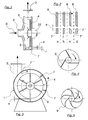
- Fig. 1 shows in a greatly simplified form the section through a device according to the invention. It can be seen the pump housing 1, in which the pump impeller 4 is located, which of the Shaft 22 is driven.
- the inlet connection 2 is central and concentric with the pump impeller 4 arranged to introduce the pulp suspension S axially centered in the pump housing 1.
- the supplied medium by means of the pump impeller 4 in Rotation offset and radially or tangentially outward through the outlet port 3 again led out, the pressure increases considerably.
- Impinging pieces 7 is shown here one in the lower part of the pump housing 1.
- baffle 7 It stretches as a survey radially inward and is on the media-contacting circumference 5 of the pump housing. 1 attached. Another possibility is to several or all baffle pieces 7 on a to attach curved stator and insert it into the pump housing 1.
- the distance e between the baffle 7 and the outermost part of the impeller 4 is advantageously about 5 - 10 mm and the radial extent r of the baffle 7 between 5 and 30mm.
- the shape of the baffles affects the fibring effect of the device.
- Fig. 2 are four Examples - a, b, c and d - shown.
- the outer ends of the pump bars 6 are relative to the fixed impact pieces 7, 7 'or 7 "moves, wherein the direction of rotation of the pump impeller indicated by an arrow.
- the baffle piece 7 has a work surface, the is parallel to the direction of the pump impeller.
- Example c) shows a work surface that is in Running direction recoils and example d) a projecting in the direction of work surface.
- the Pump bar 6 may end in accordance with example a) parallel to the running direction or also outside Beveled (see Examples b, c, d).
- the impeller 4 here has a total of six radially aligned Pump bars 6. But it is also possible, the pump bars 6 'in the form of straight and inside tangentially arranged (see Fig. 4) or of curved pump blades 9 (see Fig.5) manufacture. The latter are known to have a better efficiency, but are more complex to build.
- the direction of rotation of the pump impeller is indicated by an arrow.
- On the Media wetted circumference 5 of the pump housing 1 are here three radially aligned impact pieces. 7 attached, the baffles 8 are radially aligned.
- baffle 7 '' ' is with his Baffle 8 formed parallel to the outlet port 3, so that form a pressure edge can, which serves the pressure gain of the device.
- the shape of the baffle pieces can be different from those shown differ. It is important that in cooperation with the outer ends of the pump bars 6, 6 'or pump blades 9 unfold a fibring effect.
- Fig. 6 essentially serves to give some more details about the structure of a device according to the invention Device to show.
- the pump impeller 4 is mounted on a shaft 22, which by a motor, not shown is drivable.
- the shaft 22 is mounted in a block 10, to which serve the bearings 11 and sealed relative to the inner part of the housing 1 by a sealing device 12.
- the impact pieces 7 are mounted in the housing, one of which is shown.
- At the centrally arranged inlet connection 2 is a screwed lid 13th
- the transition between inlet port 2 and the inner part of the pump housing 1, in the The pump impeller 4 is moved here is bridged by a few removable discs 14.
- the pump housing 1 can be screwed to the foundation via the housing foot 15.
- the axial blade height H is generally between 20 and 80 mm in size.
- Fig. 7 shows a system diagram with a particularly favorable use of The subject matter.
- the pulp suspension S by dissolution of waste paper AP made with water W in a pulper 16 in a conventional manner. It enters via an im Pulper inserted below grossblochiges sieve into the annulus 17. From there it will be without further intermediate machines are pumped directly by means of the device 18 according to the invention, wherein the device 18 thus fulfills the function of the Pulperableerpumpe.
- the remaining specks decomposed so far that in the downstream sorting device 19 a Separation between contaminants 20 and 21 pulp is possible.
- Such a system therefore uses the invention optimally.
- the pulper 16 may also be act an apparatus for the dissolution of paper machine board. This usually contains no soiling and can then be processed very quickly.
- FIG. 8 Another possibility for using the subject invention is shown in FIG. 8.
- the device 18 is followed by a Vorratsbütte 24, in which the overflow 23 of one or several presortters 22 is collected.
- the overflow 23 can then be used as a stock suspension S be supplied to the device 18 according to the invention.
- a downstream of this device The reject sorter 24 then separates the contaminants 20 from the fibrous material 21 to be used.
- a discharge pump can be replaced by the device 18.
Abstract
Description
Die Erfindung betrifft eine Vorrichtung gemäß dem Oberbegriff des Anspruchs 1.The invention relates to a device according to the preamble of
Bekanntlich werden in einem großen Umfang Papierrohstoffe zur Papierherstellung in Suspension gebracht, welche einen mehr oder weniger großen Anteil an Störstoffen enthalten. Derartige Störstoffe sind überwiegend Kunststoffteile und -folien, Drähte, Glasscherben, Sand etc. Selbstverständlich sollen die Störstoffe möglichst frühzeitig aus dem Prozess entfernt werden. Zum einen, um die zur Bearbeitung benutzten Maschinen vor Verschleiß zu schützen und zum anderen wegen der Qualitätsanforderungen an das spätere Papier. Nach Vermischung mit Wasser (z.B. in einem Stofflöser) wird der Rohstoff mechanisch bearbeitet, wobei in Folge des Quellens der Papierrohstoffe diese zerfallen, während ein großer Teil der Störstoffe seine Festigkeit beibehält. Dadurch bleiben z.B. Plastikfolien relativ großflächig erhalten und können später aussortiert werden. Aber auch Stippen bleiben zu einem beträchtlichen Teil erhalten. Das hat den Nachteil, dass in den üblicherweise nachgeschalteten Sortiervorrichtungen ein Verlust der faserstoffhaltigen Stippen in Kauf genommen werden muss. Solche Sortiervorrichtungen können nämlich nicht ausreichend zwischen den unerwünschten Störstoffen, z.B. Plastikfolien und den an sich noch wertvollen faserstoffhaltigen Stippen unterscheiden.It is known that paper raw materials for paper production are in suspension to a large extent brought, which contain a more or less large amount of impurities. such Impurities are predominantly plastic parts and foils, wires, broken glass, sand etc. Of course, the impurities should be removed from the process as early as possible. To the one to protect the machines used for machining from wear and the other because of the quality requirements for the later paper. After mixing with water (e.g. a pulper) the raw material is mechanically processed, whereby as a result of the swelling of the Paper raw materials disintegrate, while a large part of the contaminants retains its strength. This leaves e.g. Plastic films received relatively large area and can be sorted out later. But also specks remain preserved to a considerable extent. This has the disadvantage that in the usually downstream sorting devices a loss of fiber-containing specks in Purchase must be taken. Indeed, such sorting devices can not do enough between the undesirable contaminants, e.g. Plastic films and the still valuable distinguish fiber-containing specks.
Der Erfindung liegt daher die Aufgabe zu Grunde, eine Vorrichtung der angegebenen Art zu schaffen, mit der es möglich ist, auf möglichst einfache Art und Weise zumindest einen großen Teil der Stippen so weit zu zerlegen, dass sie in nachgeschalteten Sortierern oder Reinigern nicht mehr ausgeschieden werden.The invention is therefore based on the object to provide a device of the type specified, with which it is possible, in the simplest possible way at least a large part of the specks disassemble them so far that they no longer work in downstream sorters or cleaners be excreted.
Diese Aufgabe wird durch die im Kennzeichen des Anspruchs 1 genannten Merkmale vollständig
gelöst. This object is achieved by the features mentioned in the characterizing part of
Mit Hilfe der erfindungsgemäßen Vorrichtung können die in der Suspension enthaltenen Stippen mit geringem Aufwand zumindest teilweise zerkleinert oder ganz aufgelöst werden. Das ist insbesondere dadurch möglich, dass sich zwischen den Prallstücken und den rotierenden Teilen des Pumpenlaufrades ein definierter Abstand befindet, der in der Regel zwischen zwei und zwanzig Millimeter, vorzugsweise fünf bis zehn Millimeter, beträgt. Ein weiterer Vorteil der Erfindung liegt darin, dass die Vorrichtung die Funktion einer ohnehin vorhandenen Apparatur, nämlich der Stoffpumpe, ebenfalls übernehmen kann. Aus diesem Grunde ist der zusätzliche apparative und energetische Aufwand relativ gering, insbesondere gemessen an dem Nutzen, den eine solche Vorrichtung bietet.With the help of the device according to the invention, the specks contained in the suspension with little effort at least partially crushed or completely dissolved. That is in particular characterized in that between the baffles and the rotating parts of the Pump impeller is a defined distance, which is usually between two and twenty Millimeters, preferably five to ten millimeters. Another advantage of the invention is in that the device has the function of an already existing apparatus, namely the Fuel pump, also can take over. For this reason, the additional apparatus and energy expenditure relatively low, especially measured by the benefits that such Device offers.
Die Erfindung und ihre Vorteile werden erläutert an Hand von Zeichnungen. Dabei zeigen:
- Fig. 1
- die erfindungsgemäße Vorrichtung in geschnittener Seitenansicht;
- Fig. 2
- verschiedene Prallstücke;
- Fig. 3
- die erfindungsgemäße Vorrichtung in Vorderansicht;
- Fig. 4
- ein Pumpenlaufrad mit tangential angeordneten Pumpenleisten;
- Fig.5
- ein Pumpenlaufrad mit gebogenen Pumpenschaufeln;
- Fig.6
- eine etwas detailliertere Darstellung des Erfindungsgegenstandes;
- Fig.7+8
- je eine Anlage mit der erfindungsgemäßen Vorrichtung.
- Fig. 1
- the device according to the invention in a sectional side view;
- Fig. 2
- various impact pieces;
- Fig. 3
- the device according to the invention in front view;
- Fig. 4
- a pump impeller with tangentially arranged pump bars;
- Figure 5
- a pump impeller with curved pump blades;
- Figure 6
- a somewhat more detailed representation of the subject invention;
- Figure 7 + 8
- ever a plant with the device according to the invention.
Die Fig. 1 zeigt in stark vereinfachter Form den Schnitt durch eine erfindungsgemäße Vorrichtung.
Man erkennt das Pumpengehäuse 1, in dem sich das Pumpenlaufrad 4 befindet, welches von der
Welle 22 angetrieben wird. Der Zulaufanschluss 2 ist zentral und konzentrisch zum Pumpenlaufrad 4
angeordnet, um die Papierstoffsuspension S axial mittig in das Pumpengehäuse 1 einzuführen. Wie
von Kreiselpumpen bekannt, wird das zugeführte Medium mit Hilfe des Pumpenlaufrades 4 in
Rotation versetzt und radial oder tangential nach außen durch den Auslaufanschluss 3 wieder
herausgeführt, wobei der Druck beträchtlich ansteigt. Zum Beschleunigen der eingeströmten
Suspension dienen die Pumpenleisten 6, die hier als Radialleisten ausgebildet sind. Von den
Prallstücken 7 ist hier eines im unteren Teil des Pumpengehäuses 1 eingezeichnet. Es erstreckt sich
als Erhebung radial nach innen und ist auf dem medienberührten Umfang 5 des Pumpengehäuses 1
befestigt. Eine andere Möglichkeit besteht darin, mehrere oder alle Prallstücke 7 auf einem
gebogenen Stator zu befestigen und diesen in das Pumpengehäuse 1 einzusetzen. Der Abstand e
zwischen dem Prallstück 7 und dem äußersten Teil des Pumpenlaufrades 4 beträgt mit Vorteil etwa
5 - 10 mm und die radiale Erstreckung r des Prallstückes 7 zwischen 5 und 30mm.Fig. 1 shows in a greatly simplified form the section through a device according to the invention.
It can be seen the
Die Form der Prallstücke beeinflusst die zerfasernde Wirkung der Vorrichtung. In Fig. 2 sind vier
Beispiele - a, b, c und d - gezeigt. Die äußeren Enden der Pumpenleisten 6 werden relativ zu den
feststehenden Prallstücken 7, 7' oder 7" bewegt, wobei die Drehrichtung des Pumpenlaufrades
durch einen Pfeil angedeutet ist. Gemäß a) und b) hat das Prallstück 7 eine Arbeitsfläche, die
parallel zur Laufrichtung des Pumpenlaufrades ist. Das Beispiel c) zeigt eine Arbeitsfläche, die in
Laufrichtung zurückweicht und Beispiel d) eine in Laufrichtung vorspringende Arbeitsfläche. Die
Pumpenleiste 6 kann gemäß Beispiel a) parallel zur Laufrichtung enden oder ebenfalls außen
abgeschrägt sein (s. Beispiele b, c, d).The shape of the baffles affects the fibring effect of the device. In Fig. 2 are four
Examples - a, b, c and d - shown. The outer ends of the
Eine ähnliche Vorrichtung wie in Fig. 1 zeigt Fig. 3 in axialer Blickrichtung, wobei das Gehäuse
geschnitten gezeichnet ist. Das Pumpenlaufrad 4 hat hier insgesamt sechs radial ausgerichtete
Pumpenleisten 6. Es ist aber auch möglich, die Pumpenleisten 6' in Form von geraden und innen
tangential angeordneten (s. Fig. 4) oder von geschwungenen Pumpenschaufeln 9 (s. Fig.5)
herzustellen. Letztere haben bekanntlich einen besseren Wirkungsgrad, sind dafür aber aufwändiger
zu bauen. Die Drehrichtung des Pumpenlaufrades ist durch einen Pfeil eingezeichnet. Auf dem
medienberührten Umfang 5 des Pumpengehäuses 1 sind hier drei radial ausgerichtete Prallstücke 7
angebracht, deren Prallflächen 8 radial ausgerichtet sind. Ein weiteres Prallstück 7''' ist mit seiner
Prallfläche 8 parallel zum Auslaufanschluss 3 ausgebildet, so dass sich eine Druckkante bilden
kann, die dem Druckgewinn der Vorrichtung dient. Die Form der Prallstücke kann von den gezeigten
abweichen. Wichtig ist, dass sie im Zusammenwirken mit den äußeren Enden der Pumpenleisten 6,
6' oder Pumpenschaufeln 9 eine zerfasernde Wirkung entfalten.A similar device as in Fig. 1, Fig. 3 in the axial direction, wherein the housing
is drawn cut. The
Fig. 6 dient im Wesentlichen dazu, etwas mehr Details über den Aufbau einer erfindungsgemäßen
Vorrichtung zu zeigen. Selbstverständlich handelt es sich dabei nur um ein Ausführungsbeispiel.
Das Pumpenlaufrad 4 ist auf einer Welle 22 befestigt, die von einem nicht gezeigten Motor
antreibbar ist. Die Welle 22 ist in einem Bock 10 gelagert, wozu die Lagerstellen 11 dienen und
gegenüber dem Innenteil des Gehäuses 1 durch eine Dichtvorrichtung 12 abgedichtet. An der
Peripherie des Pumpenlaufrades 4 sind im Gehäuse die Prallstücke 7 angebracht, von denen eines
gezeigt ist. Am zentral angeordneten Zulaufanschluss 2 befindet sich ein verschraubter Deckel 13.
Der Übergang zwischen Zulaufanschluss 2 und dem inneren Teil des Pumpengehäuses 1, in dem
das Pumpenlaufrad 4 bewegt wird, wird hier durch einige herausnehmbare Scheiben 14 überbrückt.
Das Pumpengehäuse 1 kann über den Gehäusefuß 15 mit dem Fundament verschraubt werden.
Die axiale Schaufelhöhe H ist im Allgemeinen zwischen 20 und 80 mm groß.Fig. 6 essentially serves to give some more details about the structure of a device according to the invention
Device to show. Of course, this is just an embodiment.
The
Fig. 7 zeigt ein Anlagenschema mit einer besonders günstigen Verwendung des
Erfindungsgegenstandes. Darin wird die Papierstoffsuspension S durch Auflösung von Altpapier AP
mit Wasser W in einem Stofflöser 16 in an sich bekannter Weise hergestellt. Sie gelangt über ein im
Stofflöser unten eingesetztes groblochiges Sieb in den Ringraum 17. Von dort wird sie ohne weitere
zwischengeschaltete Maschinen mit Hilfe der erfindungsgemäßen Vorrichtung 18 direkt abgepumpt,
wobei die Vorrichtung 18 also die Funktion der Pulperableerpumpe erfüllt. Gleichzeitig werden darin
die restlichen Stippen so weit zerlegt, dass in der nach geschalteten Sortiervorrichtung 19 eine
Trennung zwischen Störstoffen 20 und Faserstoffen 21 möglich ist. Eine solche Anlage nutzt daher
die Erfindung optimal aus. Für den Fall, dass der Stofflöser bei einer Konsistenz arbeitet, in der der
hergestellte Faserstoff nicht pumpfähig ist, wird zweckmäßigerweise eine hier nicht gezeigte
Verdünnung vor der Vorrichtung 18 vorzusehen sein. Bei dem Stofflöser 16 kann es sich auch um
einen Apparat zur Auflösung von Papiermaschinenausschuss handeln. Dieser enthält normalerweise
keine Verschmutzungen und kann dann sehr zügig verarbeitet werden.Fig. 7 shows a system diagram with a particularly favorable use of
The subject matter. Therein, the pulp suspension S by dissolution of waste paper AP
made with water W in a
Eine weitere Möglichkeit zur Verwendung des Erfindungsgegenstandes zeigt die Fig. 8. In diesem
Fall wird die Vorrichtung 18 einer Vorratsbütte 24 nachgeschaltet, in der der Überlauf 23 eines oder
mehrerer Vorsortierer 22 gesammelt wird. Der Überlauf 23 kann dann als Papierstoffsuspension S
der erfindungsgemäßen Vorrichtung 18 zugeführt werden. Ein dieser Vorrichtung nachgeschalteter
Rejektsortierer 24 trennt dann die Störstoffe 20 vom weiter zu verwendenden Faserstoff 21. Auch
hier kann eine Ableerpumpe durch die Vorrichtung 18 ersetzt werden.Another possibility for using the subject invention is shown in FIG. 8. In this
Case, the
Claims (14)
wobei in Folge der Pumpwirkung des Pumpenlaufrads (4) der Druck in der Papierstoffsuspension (S) erhöht wird,
dadurch gekennzeichnet, dass sich im Pumpengehäuse (1) mehrere feststehende Prallstücke (7, 7', 7", 7''') befinden, die in einem Abstand (e) zum Pumpenlaufrad (4) angeordnet sind, der zwischen 2 und 20 mm, vorzugsweise zwischen 5 und 10 mm, liegt.Device for pumping and de-stemming a paper stock suspension (S), which is formed in particular from waste paper, which has a pump housing (1) with a central inlet connection (2) and a radially outer outlet connection (3) and a pump impeller (4) through which the paper stock suspension ( S) can be conveyed from the inlet connection (2) to the outlet connection (3),
wherein as a result of the pumping action of the pump impeller (4) the pressure in the pulp suspension (S) is increased,
characterized in that in the pump housing (1) a plurality of fixed baffle pieces (7, 7 ', 7 ", 7''') are located at a distance (e) to the pump impeller (4) are arranged between 2 and 20 mm , preferably between 5 and 10 mm.
dadurch gekennzeichnet, dass die Prallstücke (7, 7', 7", 7''') radial außerhalb des Pumpenlaufrads in dessen Abströmbereich angeordnet sind.Device according to claim 1,
characterized in that the baffle pieces (7, 7 ', 7 ", 7''') are arranged radially outside the pump impeller in the outflow region.
dadurch gekennzeichnet, dass die Prallstücke (7, 7', 7", 7''') als Vorsprünge ausgebildet sind, die sich vom medienberührten Umfang (5) des Pumpengehäuses (1) nach innen erstrecken.Apparatus according to claim 1 or 2,
characterized in that the baffles (7, 7 ', 7 ", 7''') are formed as projections which extend from the media-contacting periphery (5) of the pump housing (1) inwardly.
dadurch gekennzeichnet, dass die Prallstücke (7, 7', 7") auf der von der Papierstoffsuspension (S) in Umfangsrichtung angeströmten Seite eine rechtwinklig zur Umfangsrichtung stehende Prallfläche (8) haben.Apparatus according to claim 1, 2 or 3,
characterized in that the baffles (7, 7 ', 7 ") on the side of the pulp suspension (S) flowed in the circumferential direction have a perpendicular to the circumferential direction baffle surface (8).
dadurch gekennzeichnet, dass die Prallstücke (7, 7', 7", 7''') eine radiale Erstreckung (r) von mindestens 10 mm, vorzugsweise mindestens 30 mm haben.Device according to one of the preceding claims,
characterized in that the baffles (7, 7 ', 7 ", 7''') have a radial extent (r) of at least 10 mm, preferably at least 30 mm.
dadurch gekennzeichnet, dass die Vorrichtung zwischen 3 und 12 Prallstücke (7, 7', 7", 7''') aufweist.Device according to one of the preceding claims,
characterized in that the device comprises between 3 and 12 impact pieces (7, 7 ', 7 ", 7''').
dadurch gekennzeichnet, dass das Pumpenlaufrad (4) mit radialen Pumpenleisten (6) versehen ist.Device according to one of the preceding claims,
characterized in that the pump impeller (4) is provided with radial pump bars (6).
dadurch gekennzeichnet, dass das Pumpenlaufrad mit innen tangential ausgerichteten Pumpenleisten (6') versehen ist.Device according to one of claims 1 to 6,
characterized in that the pump impeller is provided with internally tangentially aligned pump bars (6 ').
dadurch gekennzeichnet, dass das Pumpenlaufrad (4) mit gekrümmten Pumpenschaufeln (9) versehen ist.Device according to claims 1 to 6,
characterized in that the pump impeller (4) is provided with curved pump blades (9).
dadurch gekennzeichnet, dass das Pumpenlaufrad (4) einflutig ist.Device according to one of the preceding claims,
characterized in that the pump impeller (4) is single-flow.
dadurch gekennzeichnet, dass der Stofflöser (16) mit einem Sieb versehen ist, durch das die Papierstoffsuspension (S) in die Vorrichtung (18) gelangt.Use of the device according to claim 11 or 12,
characterized in that the pulper (16) is provided with a sieve through which the pulp suspension (S) enters the device (18).
Applications Claiming Priority (2)
| Application Number | Priority Date | Filing Date | Title |
|---|---|---|---|
| DE200410010857 DE102004010857A1 (en) | 2004-03-05 | 2004-03-05 | Device for pumping and de-stubbing a pulp stock containing pollutant |
| DE102004010857 | 2004-03-05 |
Publications (1)
| Publication Number | Publication Date |
|---|---|
| EP1571256A1 true EP1571256A1 (en) | 2005-09-07 |
Family
ID=34745409
Family Applications (1)
| Application Number | Title | Priority Date | Filing Date |
|---|---|---|---|
| EP05002087A Withdrawn EP1571256A1 (en) | 2004-03-05 | 2005-02-02 | Process for pumping and deflaking a fibre suspension containing impurities |
Country Status (2)
| Country | Link |
|---|---|
| EP (1) | EP1571256A1 (en) |
| DE (1) | DE102004010857A1 (en) |
Cited By (1)
| Publication number | Priority date | Publication date | Assignee | Title |
|---|---|---|---|---|
| CN104373362A (en) * | 2013-08-12 | 2015-02-25 | 苏州维艾普新材料股份有限公司 | Planar draw-off equipment for materials |
Citations (5)
| Publication number | Priority date | Publication date | Assignee | Title |
|---|---|---|---|---|
| FR2373636A1 (en) * | 1976-12-08 | 1978-07-07 | Escher Wyss Sa | OLD PAPER DISSOLUTION AND CLASSIFICATION CRUSHER |
| DE3340858A1 (en) * | 1982-11-30 | 1984-05-30 | A. Ahlström Oy, Noormarkku | Process and device for defibrating pretreated waste paper |
| US4632320A (en) * | 1984-06-09 | 1986-12-30 | Hermann Finckh Maschinenfabrik Gmbh | Apparatus for dissolving and sorting waste paper |
| DE3701400A1 (en) * | 1986-02-18 | 1987-10-08 | Voith Gmbh J M | Sorting device for fibre suspensions |
| US5730376A (en) * | 1995-06-29 | 1998-03-24 | Voith Sulzer Stoffaufbereitung Gmbh | Apparatus for regulated dispersion treatment of highly consistent fibrous substances |
Family Cites Families (3)
| Publication number | Priority date | Publication date | Assignee | Title |
|---|---|---|---|---|
| US5271805A (en) * | 1992-03-20 | 1993-12-21 | Stockel Ivar H | Method and apparatus for waste paper treatment |
| DE19637031A1 (en) * | 1996-09-12 | 1998-03-19 | Boltersdorf Hans Joachim | Recovery process for fibrous and plastic materials from rejects from pulpers |
| WO1999027177A1 (en) * | 1997-11-21 | 1999-06-03 | Thermo Black Clawson Inc. | Method for deinking and other contaminent removal from wastepaper |
-
2004
- 2004-03-05 DE DE200410010857 patent/DE102004010857A1/en not_active Ceased
-
2005
- 2005-02-02 EP EP05002087A patent/EP1571256A1/en not_active Withdrawn
Patent Citations (5)
| Publication number | Priority date | Publication date | Assignee | Title |
|---|---|---|---|---|
| FR2373636A1 (en) * | 1976-12-08 | 1978-07-07 | Escher Wyss Sa | OLD PAPER DISSOLUTION AND CLASSIFICATION CRUSHER |
| DE3340858A1 (en) * | 1982-11-30 | 1984-05-30 | A. Ahlström Oy, Noormarkku | Process and device for defibrating pretreated waste paper |
| US4632320A (en) * | 1984-06-09 | 1986-12-30 | Hermann Finckh Maschinenfabrik Gmbh | Apparatus for dissolving and sorting waste paper |
| DE3701400A1 (en) * | 1986-02-18 | 1987-10-08 | Voith Gmbh J M | Sorting device for fibre suspensions |
| US5730376A (en) * | 1995-06-29 | 1998-03-24 | Voith Sulzer Stoffaufbereitung Gmbh | Apparatus for regulated dispersion treatment of highly consistent fibrous substances |
Cited By (1)
| Publication number | Priority date | Publication date | Assignee | Title |
|---|---|---|---|---|
| CN104373362A (en) * | 2013-08-12 | 2015-02-25 | 苏州维艾普新材料股份有限公司 | Planar draw-off equipment for materials |
Also Published As
| Publication number | Publication date |
|---|---|
| DE102004010857A1 (en) | 2005-11-03 |
Similar Documents
| Publication | Publication Date | Title |
|---|---|---|
| EP0034780B1 (en) | Rotating sorter | |
| DE2526657C3 (en) | Pressure sifter for fiber suspensions | |
| DE2440393C2 (en) | Method and apparatus for recovering paper fibers from waste paper containing foreign matter | |
| EP0164428B1 (en) | Apparatus for pulping and sorting waste paper | |
| EP1679403B1 (en) | Pulper for comminuting and suspending papermaking material | |
| DE3709623A1 (en) | METHOD AND DEVICE FOR REFINING FIBER MATERIAL | |
| EP2516733A1 (en) | Method and screening device for screening a fiber suspension | |
| DE2654624B1 (en) | Material looser for breaking up and sorting waste paper | |
| DE2611886C3 (en) | Device for sorting and deflaking of fiber suspensions | |
| EP3396064B1 (en) | Device for dewatering, disassembling and conveying waste paper, pulp or wood chips | |
| EP0235605B1 (en) | Screening apparatus for paper pulp | |
| DE2757175A1 (en) | DEVICE AND METHOD FOR GRINDING AND PROCESSING WASTE MATERIALS | |
| DE102009019664A1 (en) | Process for treating a pulp suspension and screening device for its implementation | |
| DE102006008758A1 (en) | Rotor for a pressure sorter for fiber suspensions | |
| WO2016193364A1 (en) | Pressure screen | |
| EP1749923B1 (en) | Apparatus for treating a fibrous suspension | |
| EP1571256A1 (en) | Process for pumping and deflaking a fibre suspension containing impurities | |
| EP1710347A1 (en) | Process for pulping and cleaning of papermaking raw materials containing impurities | |
| DE3001448A1 (en) | PRINT SORTER | |
| WO2018114058A1 (en) | Pulper | |
| EP1609904A1 (en) | Secondary pulper for paper pulp preparation | |
| EP1130156B1 (en) | Device for separating impurities from fibrous material | |
| DE102006031904B3 (en) | Paper pulping assembly for paper recovery and recycling has rotor surrounded by ring | |
| EP0427802B1 (en) | Appliance for sorting and deflaking fibre suspensions | |
| DE2650735C2 (en) | Method and device for the production of homogeneous pulp |
Legal Events
| Date | Code | Title | Description |
|---|---|---|---|
| PUAI | Public reference made under article 153(3) epc to a published international application that has entered the european phase |
Free format text: ORIGINAL CODE: 0009012 |
|
| AK | Designated contracting states |
Kind code of ref document: A1 Designated state(s): AT BE BG CH CY CZ DE DK EE ES FI FR GB GR HU IE IS IT LI LT LU MC NL PL PT RO SE SI SK TR |
|
| AX | Request for extension of the european patent |
Extension state: AL BA HR LV MK YU |
|
| 17P | Request for examination filed |
Effective date: 20060307 |
|
| AKX | Designation fees paid |
Designated state(s): AT BE BG CH CY CZ DE DK EE ES FI FR GB GR HU IE IS IT LI LT LU MC NL PL PT RO SE SI SK TR |
|
| RAP1 | Party data changed (applicant data changed or rights of an application transferred) |
Owner name: VOITH PATENT GMBH |
|
| 17Q | First examination report despatched |
Effective date: 20080624 |
|
| STAA | Information on the status of an ep patent application or granted ep patent |
Free format text: STATUS: THE APPLICATION IS DEEMED TO BE WITHDRAWN |
|
| 18D | Application deemed to be withdrawn |
Effective date: 20081105 |