BACKGROUND OF THE INVENTION
1. Field of Invention
-
The invention relates to ink cartridges and methods of filling ink cartridges.
2. Description of Related Art
-
Inkjet printers that perform printing by ejecting ink from nozzles toward a recording
sheet may be provided with ink cartridges. Such ink cartridges are generally replaced and
disposed of after the ink contained therein has been consumed. By using ink cartridges, ink
can be easily replenished in the inkjet printer. However, spent ink cartridges are disposed of
every time ink contained therein has been consumed, which may lead to increased operating
costs. Thus, JP 3453562 discloses a technique including drilling a hole in a wall of an ink
cartridge in which ink has been consumed and refilling the ink cartridge through the hole.
-
According to the technique disclosed in JP 3453562, a hole is drilled in a side wall of
an ink cartridge, ink is introduced into the ink cartridge through the hole, and then the hole is
sealed when filling is complete. However, if drilling or sealing is done improperly, ink may
leak from the hole during operation. As such processes must be performed with considerable
care, they may be troublesome for users.
-
Ink cartridges may be formed with ink chambers into which ink is introduced from
outside using an ink syringe. As an example of this arrangement, JP-A-2003-305865
discloses attaching a synthetic rubber plug member to an ink fill portion where an ink fill hole
is formed. To fill the cartridge with ink, an injection needle of an ink syringe is inserted
through the plug member, and ink is introduced into the ink cartridge via the injection needle.
A hole, which is formed in the plug member when the injection needle is inserted, closes to
some extent by virtue of the plug member's elasticity after the injection needle is removed.
-
In the ink cartridge disclosed in JP-A-2003-305865, however, the hole formed in the
plug member when the needle is inserted may not be closed perfectly by the elasticity of the
plug member, depending on how the needle is inserted. In such cases, ink may leak from the
hole or air and impurities may be introduced to the cartridge through the hole. Also, if it is
necessary to insert an additional needle into the ink cartridge during filling, for example for
deaeration, the filling needle and the additional needle may be inserted into similar positions
on the plug member producing a comparatively large hole. It may be difficult to seal such a
large hole relying only on the elasticity of the plug member.
-
It is the object of the invention to provide an ink cartridge that can reliably be refilled
and a method of filling ink cartridges that allows reliably filling.
SUMMARY
-
In view of the above problems the disclosure provides an ink cartridge capable of
sealing a hole to be formed in a plug member when a needle is inserted into the plug member
for ink filling with reliability, and a method of filling ink cartridges that can be performed
with facility.
-
The object is solved by a method according to claim 1.
-
Thus, without modification to the ink cartridge, the ink tank can be easily filled. In
addition, ink can be repeatedly supplied in the ink tank, thereby allowing reuse of the
cartridge and reducing the operating costs.
-
It is preferable that the ink supply tube is a syringe needle and the sealing member is
formed of a material having an elasticity such that a hole formed by the syringe needle will
tend to close itself when the syringe needle is removed.
-
With this structure, the hole can be closed by elastic force inherent in the sealing
member with reliability.
-
It is preferable that the method further includes moving the sealing member from the
first region to a second region in the ink inflow passage adjacent to the second opening before
inserting the ink supply tube.
-
With these steps, the sealing member can make intimate contact with the first opening
of the ink inflow passage that communicates with the ink tank. In addition, ink can be easily
introduced.
-
It is preferable that the method further includes removing the ink supply tube from the
ink inflow passage, and moving the sealing member from the second region to the first
region. It is preferable that moving the sealing member from the second region to the first
region includes moving the sealing member into a position such that a surface of the sealing
member seals the first opening, the surface being a surface that has not been penetrated by the
ink supply tube.
-
With this structure, even if the tube is inserted into the sealing member over and over
again and the sealing member becomes fatigued, the first opening can be sealed with
reliability.
-
The method may include: inserting an air communication tube through the sealing
member and into a first region in the ink inflow passage adjacent to the first opening.
-
It is preferable that the method further includes moving the sealing member from the
first region to a second region in the ink inflow passage adjacent to the second opening before
inserting the air communication tube and the ink supply tube.
-
With these steps, the sealing member can make intimate contact with the first opening
of the ink inflow passage that communicates with the ink tank. In addition, ink can be easily
introduced.
-
It is preferable that the method further includes removing the air communication tube
and the ink supply tube from the ink inflow passage, and moving the sealing member from
the second region to the first region. It is preferable that moving the sealing member from the
second region to the first region includes moving the sealing member into a position such that
a surface of the sealing member seals the first opening, the surface being a surface that has
not been penetrated by the air communication tube or the ink supply tube.
-
With this structure, even if the tube is inserted into the sealing member over and over
again and the sealing member becomes fatigued, the first opening can be sealed with
reliability.
-
It is preferable that the air communication tube and the ink supply tube are a syringe
needles and the sealing member is formed of a material having an elasticity such that holes
formed by the syringe needles will tend to close themselves when the syringe needles are
removed.
-
With this structure, the hole can be closed by elastic force inherent in the sealing
member with reliability.
-
The object is also attained by a method according to claim 13.
-
Thus, without modification to the ink cartridge, the ink tank can be easily filled. In
addition, ink can be repeatedly supplied in the ink tank, thereby allowing reuse of the
cartridge and reducing the operating costs.
-
It is preferable that the first region has a truncated conical shape and moving the
sealing member from the second region to the first region includes moving the sealing
member into the first region so that it contacts an end surface of the ink inflow passage
opposite from the second opening.
-
Thus, when the sealing member is in contact with the end surface in the first region,
the first opening can be sealed with the sealing member with reliability.
-
The object is also attained by an ink cartridge according to claim 19.
-
In such an ink cartridge, a sealing member having elasticity is force-fitted into the ink
inflow passage. When a needle of an ink syringe is inserted through the sealing member, ink
is introduced into the ink tank via the injection needle. Thus, with the injection needle
removed from the sealing member after ink filling, the sealing member is force-fitted into the
ink inflow passage until it is located in the first region, thereby increasing a compression
force acting on the sealing member from the ink inflow passage. As a result, a through hole
formed through the sealing member on insertion of the injection needle can be closed with
reliability.
-
It is preferable that the ink cartridges further include a stepped portion between the
first region and the second region.
-
Thus, with the injection needle removed from the sealing member after ink filling, the
sealing member is force-fitted into the ink inflow passage until it is located to the portion
nearer the ink tank from the stepped portion, thereby increasing a compression force acting on
the elastic member from the ink inflow passage. As a result, a through hole formed through
the elastic member on insertion of the injection needle can be closed with reliability.
-
It is preferable that a first angle between the first region and the stepped portion and a
second angle between the second region and the stepped portion are obtuse.
-
Thus, when the injection needle is removed from the sealing member after ink filling
and the sealing member is force-fitted into the ink inflow passage from the second region to
the first region, resistance acting on the sealing member becomes relatively small, thereby
facilitating a force-fit operation.
-
It is preferable that the second opening is partitioned into multiple openings.
-
Thus, when it is necessary to insert the injection needle and another needle in the ink
cartridge, for example, for deaeration, the needles can be inserted from respective partitioned
entrances, thereby preventing formation of a large through hole. Further, the sealing member
can be prevented from coming off from the ink inflow passage.
-
It is preferable that the ink inflow passage includes a side wall and an end surface, the
first region is provided in a truncated conical shape, and the first opening is provided on the
side wall at a location adjacent to the end surface.
-
Thus, when the sealing member is in contact with the end surface in the first region,
the first opening can be sealed with the sealing member with reliability. Further, because the
first opening is provided on the side wall at the location adjacent to the end surface, a through
hole, which is formed when a needle is inserted into the sealing member, and the first opening
are spaced away from each other in plan view of the sealing member. Thus, when the sealing
member is force-fitted into the end surface of the ink inflow passage, the first opening can be
securely sealed by the sealing member regardless of the size of the through hole.
-
Further developments of the invention are specified in the subordinate claims,
respectively.
BRIEF DESCRIPTION OF THE DRAWINGS
-
Various embodiments of the invention will be described in detail with reference to the
following figures, wherein:
- FIG. 1 is a schematic illustration of an inkjet printer according to an embodiment of
the present invention in which ink cartridges are installed;
- FIG. 2A is a plan view of an ink cartridge according to an embodiment of the present
invention;
- FIG. 2B is a side view of the ink cartridge;
- FIG. 2C is a bottom view of the ink cartridge;
- FIG. 3 is a perspective view of the ink cartridge;
- FIG. 4 is a sectional view of the ink cartridge shown in FIG. 2B, taken along the line
IV-IV;
- FIG. 5A is a sectional view of the ink supply valve shown in FIG. 4 in a closed state;
- FIG. 5B is a sectional view of the ink supply valve shown in FIG. 4 in an open state;
- FIG. 6 is a perspective view of the valve body shown in FIG. 4;
- FIG. 7 is a sectional view of an ink cartridge showing a phase of an ink filling method
according to a first embodiment of the present invention;
- FIG. 8 is a sectional view of the ink cartridge showing a phase of the ink filling
method;
- FIG. 9 is a sectional view of the ink cartridge showing a phase of the ink filling
method;
- FIG. 10 is a sectional view of the ink cartridge showing a phase of the ink filling
method;
- FIG. 11 is a sectional view of the ink cartridge showing a phase of the ink filling
method;
- FIG. 12 is a sectional view of the ink cartridge showing a phase of an ink filling
method according to a second embodiment of the present invention;
- FIG. 13 is a sectional view of the ink cartridge showing a phase of the ink filling
method according to the second embodiment;
- FIG. 14 is a sectional view of the ink cartridge showing a phase of the ink filling
method;
- FIG. 15 is a sectional view of the ink cartridge showing a phase of an ink filling
method according to a third embodiment of the present invention;
- FIG. 16 is a sectional view of the ink cartridge showing a phase of the ink filling
method;
- FIG. 17 is a sectional view of the ink cartridge showing a phase of the ink filling
method;
- FIG. 18 is a sectional view of the ink cartridge showing a phase of the ink filling
method;
- FIG. 19 is a sectional view of the ink cartridge showing a phase of the ink filling
method;
- FIG. 20 is a sectional view of the ink cartridge showing a phase of an ink filling
method according to a fourth embodiment of the present invention;
- FIG. 21 is a sectional view of the ink cartridge showing a phase of the ink filling
method;
- FIG. 22 is a sectional view of the ink cartridge showing a phase of an ink filling
method according to a fifth embodiment of the present invention;
- FIG. 23 is a sectional view of an ink cartridge;
- FIG. 24 is an enlarged view of a portion of the ink cartridge shown in FIG. 23;
- FIG. 25A is a plan view of the ink cartridge;
- FIG. 25B is a side view of the ink cartridge;
- FIG. 25C is a bottom view of the ink cartridge;
- FIG. 26 is a perspective view of the ink cartridge, as viewed from below;
- FIG. 27 is a sectional view of the ink cartridge shown in FIG. 25B, taken along the
line IV-IV;
- FIG. 28 is an enlarged view of a portion of the ink cartridge shown in FIG. 27;
- FIG. 29A is a partial sectional view of the ink cartridge showing a phase of an ink
filling method;
- FIG. 29B is a partial sectional view of the ink cartridge showing a phase of the ink
filling method;
- FIG. 29C is a partial sectional view of the ink cartridge showing a phase of the ink
filling method;
- FIG. 29D is a partial sectional view of the ink cartridge showing a phase of the ink
filling method;
- FIG. 29E is a partial sectional view of the ink cartridge showing a phase of the ink
filling method;
- FIG. 30A is a partial sectional view of an ink cartridge according to another
embodiment; and
- FIG. 30B is a partial sectional view of an ink cartridge according to still another
embodiment.
-
DETAILED DESCRIPTION OF EMBODIMENTS
-
Throughout the following description, numerous specific concepts and structures are
set forth in order to provide a thorough understanding of the invention. The invention can be
practiced without utilizing all of these specific concepts and structures. In other instances,
well known elements have not been shown or described in detail, so that emphasis can be
focused on the invention.
-
A first embodiment of the invention will be described in detail below. Embodiments
of the invention are applicable to an ink cartridge attachable to an inkjet printer that is capable
of ejecting ink of four colors. As shown in FIG. 1, the inkjet printer 1 includes an inkjet head
2 having nozzles 2a that eject ink of four colors, cyan (C), yellow (Y), magenta (M), and
black (K) onto a recording sheet P; four holders 4 (4a, 4b, 4c, and 4d) in which four ink
cartridges 3 (3a, 3b, 3c, 3d) containing ink of one of the four colors respectively are installed;
a carriage moving mechanism 5 that reciprocates the inkjet head 2 linearly in a direction
along guides 9 (in a direction perpendicular to the drawing sheet); a conveying mechanism 6
that conveys the recording sheet P in a direction perpendicular to the moving direction of the
inkjet head 2 and parallel to an ink ejection surface of the inkjet head 2; and a purge device 7
that suctions air bubbles and thick ink from the inkjet head 2.
-
In the inkjet printer 1, the inkjet head 2 is reciprocated by the carriage moving
mechanism 5 in a direction perpendicular to the drawing sheet of FIG. 1, while the recording
sheet P is conveyed by the conveying mechanism 6 in a left-right direction on the page in
FIG. 1. Concurrently, ink is supplied from the ink cartridges 3 installed in the holders 4 via a
supply tube 10 to the nozzles 2a of the inkjet head 2, and ink is ejected from the nozzles 2a
toward the recording sheet P, so that printing is performed on the recording sheet P.
-
The purge device 7 includes a purge cap 11 and a suction pump 7a. The purge cap 11
is movable in directions toward or away from the ink ejection surface and is detachably
attachable to the inkjet head 2 so as to cover the ink ejection surface. The suction pump 7a
suctions ink and/or air from the nozzles 2a. When the inkjet head 2 is located outside of an
area where it can print on the recording sheet P, the purge device 7 is capable of suctioning
air bubbles or ink having a high viscosity as a result of evaporation of volatile elements,
trapped in the inkjet head 2 from the nozzles 2a by the action of the suction pump 7a.
-
The four holders 4a to 4d are arranged in a line and attached to the corresponding ink
cartridges 3a to 3d each storing one of cyan, yellow, magenta, and black inks, respectively.
At a bottom portion of each holder 4, an ink extraction tube 12 and an air introducing tube 13
(FIG. 4) are disposed so as to correspond to an ink supply valve 21 and an air communication
valve 22 in the ink cartridge 3. The holder 4 is also provided with an optical sensor 14 for
detecting a remaining amount of ink (ink level) in the ink cartridge 3. The sensor 14 has a
light emitting portion 14a and a light receiving portion 14b that are positioned at the same
height in a face-to-face relationship with each other so as to sandwich at least a portion of the
ink cartridge 3 therebetween. The sensor 14 detects whether light from the light emitting
portion 14a is interrupted by a shutter mechanism 23 provided in the ink cartridge 3, and
outputs the detection result to a control device (not shown) that governs operation of the
inkjet printer 1.
-
The ink cartridge 3 will be further described with reference to FIGS. 2-7. As the ink
cartridges 3a-3d are identical in shape, structure and operation with each other, except that
each contains a different color of ink, the following description will be made with respect to
one ink cartridge.
-
As shown in FIGS. 2-4, the ink cartridge 3 is provided with a cartridge body 20, the
ink supply valve (ink valve) 21, the air communication valve (air valve) 22, a shutter
mechanism 23, and a cap 24. The cartridge body 20 contains ink therein. The ink supply
valve (ink valve) 21 is capable of opening and closing an ink supply passage through which
ink in the cartridge body 20 is supplied to the ink jet head 2. The air communication valve 22
is capable of opening and closing an air introducing passage through which air can be
transmitted to the cartridge body 20 from outside of the cartridge 3. The shutter mechanism
23 obstructs light emitted by the light emitting portion 14a of the sensor 14 to detect an ink
level. The cap 24 covers a lower end portion of the cartridge body 20.
-
The cartridge body 20 may be made of a synthetic resin having light permeability. As
shown in FIG. 4, a partition wall 30 that extends horizontally is integrally formed with the
cartridge body 20. The partition wall 30 divides an internal space of the cartridge body 20
into an ink chamber (ink tank) 31, which is situated above the partition wall 30, and two
valve chambers 32 and 33, which are situated below the partition wall 30. Ink is stored in the
ink chamber 31. The ink supply valve 21 and the air communication valve 22 are
accommodated in the valve chambers 32, 33, respectively.
-
As shown in FIG. 2B, a protruding portion 34, which protrudes outwardly, is formed
at a substantially central portion of a side of the cartridge body 20 with respect to its height.
A light-shielding plate 60 of a shutter mechanism 23 is disposed in a space defined by the
protruding portion 34. With the ink cartridge 3 attached to the holder 4, the protruding
portion 34 is sandwiched between the light emitting portion 14a and the light-receiving
portion 14b of the sensor 14. A lid member 35 is welded at an upper end portion of the
cartridge body 20, to enclose the ink chamber 31 in the cartridge body 20.
-
As shown in FIG. 4, an ink fill hole (ink inflow passage) 36 for introducing ink to the
ink chamber 31 of the ink cartridge 3 is formed between the two valve chambers 32, 33. The
ink fill hole 36 communicates with the ink chamber 31 in the cartridge body 20 via an upper
opening 36a and communicates with the outside via a lower opening 36b. A sealing or plug
member 37, such as an elastic (e.g., synthetic rubber) plug member, is force-fitted into an
upper end of the ink fill hole 36. The plug member 37 is cylindrical and seals the opening
36a at its peripheral side surface.
-
A tubular portion 38, which protrudes downward, is integrally formed with a portion
of the partition wall 30 that forms a top portion of the valve chamber 32 where the ink supply
valve 21 is accommodated. The tubular portion 38 is provided, at its lower end, with a thin
film portion 39 that closes a passage formed in the tubular portion 38. Tubular portions 40,
41, which protrude upward and downward, respectively, are integrally formed with the
partition wall 30 that forms a top portion of the valve chamber 33 where the air
communication valve 22 is accommodated. The lower tubular portion 41 is provided with a
thin film portion 42 that closes passages formed in the tubular portions 40, 41 at a lower end.
The tubular portion 40 is provided, at its upper end, with a tubular member 43 that extends to
the upper end of the ink chamber 31.
-
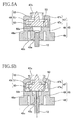
As shown in FIGS. 4, 5A and 5B, the ink supply valve 21 includes a valve housing 45
and a valve body 46. The valve housing 45 may be made of a synthetic rubber, and is formed
in a substantially tubular shape and has elasticity. The valve body 46 may be made of a
synthetic resin and is accommodated in the valve housing 45. The valve housing 45 includes
an urging member 47, a valve seat 48, and an engaging portion 49, which are arranged in this
order from the upper end (the ink chamber 31 side) and formed integrally.
-
A bottom surface of the valve body 46 makes contact with a top surface of the valve
seat 48 (an end surface facing the ink chamber 31). A through hole 48a extending vertically
is formed substantially in a central axis of the valve seat 48. The engaging portion 49 has a
guide hole 49a that communicates with the through hole 48a and extends downwardly. The
guide hole 49a is shaped such that its diameter becomes greater toward the bottom end.
Around the guide hole 49a, a circular groove 49b is formed. The groove 49b allows a wall
portion forming the guide hole 49a to deform elastically and easily toward a direction that the
diameter of the guide hole 49a becomes greater. Thus, when the ink extraction tube 12 is
inserted into the guide hole 49a, a sealing fit between the guide hole 49a and the ink
extraction tube 12 is improved thereby preventing ink leakage as much as possible. Even if
the ink extraction tube 12 is inserted into the guide hole 49a on a slant or is not completely
inserted into the guide hole 49a, the ink extraction tube 12 can be inserted into the guide hole
49a with reliability because the wall portion forming the guide hole 49a deforms in a
direction that causes the diameter of the guide hole 49a to become greater.
-
The urging member 47 has a side wall portion 47a and an overhang 47b. The side wall
portion 47a extends from the outer surface of the valve seat 48 upwardly toward the ink
chamber 31. The overhang 47b is integral with the side wall portion 47a and extends radially
inward from the upper end of the side wall portion 47a. The bottom surface of the overhang
47b makes contact with the valve body 46, and the valve body 46 is urged downward by
elastic force of the side wall portion 47a and the overhang 47b. In addition, an opening 47c is
formed inside the overhang 47b, so that the side wall portion 47a and the overhang 47b,
which are integrally formed, are easily deformed.
-
As shown in FIGS. 5A, 5B and 6, the valve body 46 has a bottom portion 50, a valve
side wall portion 51, and a breaking portion 52. The bottom portion 50 makes contact with
the valve seat 48. The valve side wall portion 51 is formed in a tubular shape and extends
from the valve side wall portion 51 upward toward the ink chamber 31. The breaking portion
52 projects from a center of the bottom portion 50 toward the ink chamber 31 higher than the
valve side wall portion 51.
-
An annular protrusion 50a that protrudes toward the valve seat 48 is formed at the
bottom surface of the bottom portion 50 (which is an end surface facing the valve seat 48). In
a state where the valve body 46 is urged toward the valve seat 48 by the urging member 47
and the annular protrusion 50a is in contact with the top surface of the valve seat 48, the
through hole 48a of the valve seat 48 is closed by the valve body, and thus the ink supply
passage is closed. Further, a plurality of passages (e.g. eight passages in this embodiment) 53
are formed at equal intervals in the bottom portion 50 in between the outside of the annular
protrusion 50a and the inside of the valve side wall portion 51. The passages 53 provide
communication between the upper space above the valve body 46 and the lower space below
the valve body 46.
-
As shown in FIGS. 5A, 5B, and 6, the breaking portion 52 is made up of four plate- like
members 52a, 52b, 52c, 52d that are assembled in the shape of a cross in a plan view, and
is held upright relative to a substantially central portion of the bottom portion 50. Grooves 54
that extend vertically are formed between the four plate-like members 52a to 52d. The
breaking portion 52 protrudes upwardly through the opening 47c inside of the overhang 47b
such that its end is disposed at a place slightly lower than the thin film portion 39 as shown in
FIG. 4.
-
When the ink cartridge 3 is attached to the holder 4, the ink extraction tube 12 is
inserted into the guide hole 49a. The valve body 46 is pressed up by the tip of the ink
extraction tube 12 against the urging force of the urging member 47. The valve body 46
moves upward while deforming the urging member 47, and the annular protrusion 50a is
separated from the valve seat 48. At this time, the thin film portion 39 is broken by the end of
the breaking portion 52 of the valve body 46 moving upward, so that ink in the ink chamber
31 flows into the valve chamber 32 via the passage in the tubular portion 38, as shown in
FIGS. 4 and 5B. In addition, ink is supplied from the ink extraction tube 12 to the inkjet
printer 1 via the passages 53 of the valve body 46.
-
As in the case of the ink supply valve 21 shown in FIGS. 5A and 5B, the air
communication valve 22 also includes the valve housing 45 and the valve body 46
accommodated in the valve housing 45. That is, the air communication valve 22 is also
structured so that the valve body 46 is urged downward by the urging member 47 and brought
into intimate contact with the valve seat 48 of the valve housing 45 so as to close the through
hole 48a. When the ink cartridge 3 is attached to the holder 4, the air introducing tube 13 is
inserted into the guide hole 49a formed in the valve housing 45, the valve body 46 moves up
and the thin film portion 42 of the tubular portion 41 is broken by the breaking portion 52.
Subsequently, air flows into the valve chamber 33 from the air introducing tube 13 via the
passages 53 of the valve body 46, and air is guided to an upper part of the ink chamber 31.
-
As shown in FIG. 4, the shutter mechanism 23 is disposed in a lower portion of the
ink chamber 31, and includes the light-shielding plate 60, a hollow float 61, a connecting
member 62 that connects the light-shielding plate 60 and the float 61, and a support stand 63
that pivotally supports the connecting member 62 disposed above the partition wall 30. The
light-shielding plate 60 and the float 61 are provided at both ends of the connecting member
62. The connecting member 62 is disposed within a vertical plane parallel to the sheet of
FIG. 4 so as to pivot on a central point of the support stand 63.
-
The light-shielding plate 60 is a thin plate in parallel with the vertical plane and
having a specified area. With the ink cartridge 3 attached to the holder 4, the light emitting
portion 14a and the light receiving portion 14b reach a height equal to the protruding portion
34 formed at a side wall portion of the cartridge body 20. When the light-shielding plate 60 is
positioned in a space defined by the protruding portion 34, the light-shielding plate 60
prevents light emitted by the light emitting portion 14a of the sensor 14 from passing through
a transparent wall portion of the cartridge body 20 and ink in the ink chamber 31. The float
61 is a cylindrical member filled with air, and its specific gravity is smaller than the specific
gravity of ink in the ink chamber 31.
-
Thus, when the ink level in the ink chamber 31 is high and the float 61, which is
provided at one end of the connecting member 62, is entirely submerged in ink, the float 61
floats toward the surface of the ink and the light-shielding plate 60, which is provided at the
other end of the connecting member 62, is located at a position in the protruding portion 34 (a
position indicated by a solid line in FIG. 4) such that light emitted by the light emitting
portion 14a is prevented from passing through the protruding portion 34. On the other hand,
when the ink level is decreased and a part of the float 61 starts to rise to the surface of the ink,
buoyancy will cause the float 61 to descend with the ink level. At this time, the light-shielding
plate 60 moves to a position higher than the protruding portion 34 (a position
indicated by a chain line in FIG. 4) so that the light-shielding plate 60 does not prevent light
emitted by the light emitting portion 14a from passing through the protruding portion 34.
Thus, unobstructed by the light-shielding plate 60, light emitted by the light emitting portion
14a passes through the protruding portion 34 and ink in the ink chamber 31, and is received
by the light receiving portion 14b. In this way, the low ink level is detected by the sensor 14.
-
As shown in FIGS. 2-4, the cap 24 is fixed to the cartridge body 20, for example, by
ultrasonic welding to cover the lower end portion of the cartridge body 20. At the bottom of
the cap 24, two annular protrusions 65 that protrude downwardly are formed at positions
corresponding to the ink supply valve 21 and the air communication valve 22. By virtue of
the annular protrusions 65, when the ink cartridge 3 is placed, for example, on a desk, ink
adhered to outer surfaces of the ink supply valve 21 or the air communication valve 22 is less
likely to be transferred to the surface of the desk.
-
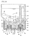
An exemplary method of filling an ink cartridge 3 where ink has been used up and the
ink chamber 31 has become empty will be described with reference to FIGS. 7 to 11. As
shown in FIG. 7, the ink cartridge 3 in which the ink chamber 31 has become empty is
removed from the holder 4. To prevent ink from flowing in the valve chamber 33 via the
tubular member 43 when ink is filled into the ink chamber 31, the ink cartridge 3 is
positioned so that an opening of the tubular member 43 that communicates with the ink
chamber 31 faces up. Then, as shown in FIG. 8, an air ventilation tube 77 is inserted into the
guide hole 49a of the air communication valve 22 in a direction of an arrow 101, so that the
air communication valve 22 is opened. Then, the plug member 37 disposed so as to seal the
opening 36a of the ink fill hole 36 is separated away from the opening 36a in the direction of
the arrow 102 and disposed near the opening 36b.
-
As shown in FIG. 9, an injection needle (ink supply tube) 75 of an ink syringe (not
shown) is inserted into the plug member 37 in a direction of an arrow 103 such that the
injection needle 75 passes through and is exposed from the top surface of the plug member
37. At this time, the injection needle 75 should be inserted until an ink outlet 75a formed
near the tip of the injection needle 75 is positioned completely through the plug member 37
and toward the ink chamber 31. That is, the ink outlet 75a should be located nearer the ink
chamber 31 than the plug member 37 is. Then the ink syringe is operated so that ink is
introduced into the cartridge body 20. As shown in FIG. 10, the introduced ink passes
through the inside of the injection needle 75 past the plug member 37 and is discharged into
the ink fill hole 36 from the ink cutlet 75a. The introduced ink flows in the ink chamber 31
through the opening 36a of the ink fill hole 36 (in a direction of an arrow 104). At this time,
as shown by an arrow 105, air in the ink chamber 31 corresponding to an amount of the
introduced ink is discharged from the ink chamber 31 through the air communication valve
22 and the air ventilation tube 77. When the ink chamber 31 has been filled to a desired
level, filling with the ink syringe is stopped. The amount of the introduced ink is preferably
an amount sufficient to cause the ink to reach a level near the opening of the tubular member
43 in the ink chamber 31, but not higher than the opening of the tubular member 43 (even if
the ink level rises when the cartridge is resealed).
-
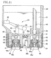
As shown in FIG. 11, the injection needle 75 is pulled out from the plug member 37.
At this time, a through hole, which is formed in the plug member 37 after the injection needle
75 is inserted, is closed by elastic force inherent in the plug member 37. Thereafter, the plug
member 37 disposed near the opening 36b is moved up to the upper end of the ink fill hole 36
in a direction of an arrow 106 so as to seal the opening 36a at its peripheral side surface.
When sealing of the opening 36a is completed, the air ventilation tube 77 is pulled out from
the guide hole 49a of the air communication valve 22, the air communication valve 22 is
closed, and the filling is complete.
-
According to the embodiment shown in FIGS. 7-11, the ink chamber 31 can be easily
filled with ink without modifying to the cartridge body 20. In addition, ink can be repeatedly
supplied in the cartridge body 20, thereby allowing reuse of the cartridge body 20 and
reducing the operating costs. The plug member 37 is separated from the opening 36a, so that
ink can be easily filled through the ink fill hole 36 at a location nearer to the ink chamber 31
than the plug member 37.
-
In the embodiment shown in FIGS. 7-11, the plug member 37 seals the opening 36a at
its peripheral side surface and the injection needle 75 of the ink syringe is exposed from the
top surface of the plug member 37. With this construction, even when the injection needle 75
is inserted into the plug member 37 over and over again and the top and bottom end surfaces
of the plug member 37 become fatigued, ink leakage from the ink fill hole 36 can be
prevented at the peripheral side surface of the plug member 37, which is not fatigued. With
this construction, the number of times that refilling can be performed is increased, and thus
operating costs are reduced.
-
Removal of the air ventilation tube 77 is carried out after sealing with the plug
member 37 is performed. Accordingly, a pressure increase associated with resealing does not
occur, and a condition that might adversely affect ink meniscus formation at nozzles 2a does
not occur. Accordingly, a stable ink supply is protected.
-
A second embodiment of the invention is described with reference to FIGS. 12-14,
which depict a method of filling with respect to an ink cartridge 3, which has a configuration
similar or the same as the ink cartridge 3 shown in FIGS. 7-11. Accordingly, like reference
numerals are used and description of like features is omitted in the interest of brevity.
-
As shown in FIG. 12, the ink cartridge 3 in which the ink chamber 31 has become
empty is removed from the holder 4. The ink cartridge 3 is placed with an opening of the
tubular member 43 that communicates with the ink chamber 31 face up. One end of a pump
tube 91a, which is connected to a pump 91 at the other end, is inserted into the guide hole 49a
of the air communication valve 22 in a direction of an arrow 201, so that the air
communication valve 22 is opened. Then, the plug member 37, disposed so as to seal the
opening 36a of the ink fill hole 36, is separated away from the opening 36a in the direction of
the arrow 202 and is disposed near the opening 36b. Using the pump 91, air in the ink
chamber 31 is suctioned until pressure is reduced to a specified value. When pressure
reduction of the ink chamber 31 is completed, the pump tube 91 a is pulled out from the guide
hole 49a.
-
A shown in FIG. 13, an injection needle 75 connected to an ink tank for ink filling
(not shown) is inserted into the plug member 37 in a direction of an arrow 203 such that the
injection needle 75 passes through and is exposed from the top surface of the plug member
37. At this time, the injection needle 75 should be inserted until an ink outlet 75a formed
near the tip of the injection needle 75 is located at a position completely through the plug
member 37 and toward the ink chamber 31. As the ink chamber 31 is under reduced pressure,
ink in the ink tank for filling passes through the inside of the injection needle 75, through the
plug member 37 and is discharged in the ink fill hole 36 from the ink outlet 75a. The
introduced ink flows into the ink chamber 31 through the opening 36a of the ink fill hole 36
(in a direction of an arrow 204). When the ink chamber 31 is full of ink, pressure in the ink
chamber reaches a specified value and ink filling is stopped. In embodiments, ink filling is
stopped while the ink chamber 31 is kept under a negative pressure.
-
Then, the injection needle 75 is pulled out from the plug member 37. At this time, a
through hole, which is formed in the plug member 37 after the injection needle 75 is inserted,
is closed by the elastic force of the plug member 37. Thereafter, the plug member 37
disposed near the opening 36b is moved up to the upper end of the ink fill hole 36 in a
direction of an arrow 106 so as to seal the opening 36a at its peripheral side surface. This
completes ink filling.
-
By employing the method shown in FIGS. 12-14, the ink chamber 31 can be easily
filled without modification to the cartridge body 20. In embodiments, ink filling is stopped
while the ink chamber 31 is kept under a negative pressure. Accordingly, air present in ink
can be controlled, and ink ejection properties of the ink can be maintained stably for long
periods.
-
A third embodiment of the invention is described with reference to FIGS. 15-19,
which depict a method of filling with respect to an ink cartridge 3, which has a configuration
similar or the same as the ink cartridge 3 shown in FIGS. 7-14. Accordingly, like reference
numerals are used and description of like features is omitted in the interest of brevity.
-
As shown in FIG. 15, the ink cartridge 3 in which the ink chamber 31 has become
empty is removed from the holder 4. To prevent ink from flowing in the valve chamber 32
when ink is filled into the ink chamber 31, the removed ink cartridge 3 is placed with the
valve chamber 32 positioned up. As shown in FIG. 16, the air ventilation tube 77, is inserted
into the guide hole 49a of the ink supply valve 21 in a direction of an arrow 301, so that the
ink supply valve 21 is open. Then, the plug member 37 disposed so as to seal the opening
36a of the ink fill hole 36 is separated away from the opening 36a in a direction of an arrow
302 and is disposed near the opening 36b.
-
As shown in FIG. 17, the injection needle 75 of an ink syringe (not shown) is inserted
into the plug member 37 in a direction of an arrow 303 such that the injection needle 75
passes through the plug member 37. At this time, the injection needle 75 should be inserted
until the ink outlet 75a formed near the tip of the injection needle 75 is located toward the ink
chamber 31 completely through the plug member 37. That is, the ink outlet 75a should be
located nearer the ink chamber 31 than the plug member 37 is. Then the ink syringe is
operated such that ink is introduced into the ink chamber 31. As shown in FIG. 18, the
introduced ink passes through the inside of the injection needle 75, through the plug member
37 and is discharged in the ink fill hole 36 from the ink outlet 75a. Further, the introduced
ink flows in the ink chamber 31 from the opening 36a of the ink fill hole 36 (in a direction of
an arrow 304). At this time, as shown by an arrow 305, air in the ink chamber 31 is
discharged outside through the ink supply valve 21 in accordance with an amount of the
introduced ink. When ink is filled into the ink chamber 31, the ink filling by the ink syringe
is stopped.
-
As shown in FIG. 19, the injection needle 75 is pulled out from the plug member 37.
At this time, a through hole, which is formed in the plug member 37 after the injection needle
75 is inserted, is closed by itself due to elastic force exerted by the plug member 37.
Thereafter, the plug member 37 disposed near the opening 36b is moved down to the lower
end of the ink fill hole 36 in a direction of an arrow 306 so as to seal the opening 36a at its
peripheral side surface. When sealing of the opening 36a is completed, the air ventilation
tube 77 is pulled out from the guide hole 49a of the ink supply valve 21, the ink supply valve
21 is closed, and the ink filling is completed.
-
In the embodiment shown in FIGS. 15-19, the ink chamber 31 can be easily filled
without modification to the cartridge body 20. Ink is introduced in accordance with the
amount of air discharged outside through the air ventilation tube 77. Thereby, substantially
the entire of the volume of the ink chamber 31 can be filled with ink, so that ink filling
efficiency is high.
-
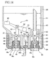
A fourth embodiment of the invention is described with reference to FIGS. 20 and 21,
which depict a method of filling with respect to an ink cartridge 3, which has a configuration
similar or the same as the ink cartridge 3 shown in FIGS. 7-19. Accordingly, like reference
numerals are used and description of like features is omitted in the interest of brevity.
-
As shown in FIG. 20, the ink cartridge 3 in which the ink chamber 31 has become
empty is removed from the holder 4. To prevent ink from flowing in the ink fill hole 36 when
the ink chamber 31 is filled, the removed ink cartridge 3 is placed with the opening 36a of the
ink fill hole 36 positioned up. As shown in FIG. 20, the plug member 37 positioned so as to
seal the opening 36a of the ink fill hole 36 is separated away from the opening 36a in a
direction of an arrow 402 and disposed near the opening 36b.
-
A ventilation needle (air communication tube) 76 for communication with air is
inserted into the plug member 37 in a direction of an arrow 401 such that the ventilation
needle 76 passes through the bottom surface of the plug member 37. At this time, the
ventilation needle 76 should be inserted until a communication hole 76a formed near the tip
of the ventilation needle 76 is located completely through the plug member 37 toward the ink
chamber 31. That is, the communication hole 76a should be located nearer the ink chamber
31 than the plug member 37 is. In addition, the injection needle 75 of an ink syringe (not
shown) is inserted into the plug member 37 such that the injection needle 75 passes through
the bottom surface of the plug member 37 (in a direction of an arrow 403). At this time, the
injection needle 75 should be inserted until the ink outlet 75a formed near the tip of the
injection needle 75 is located completely through the plug member 37 toward the ink chamber
31. That is, the ink outlet 75a should be located nearer the ink chamber 31 than the plug
member 37 is. Then the ink syringe is operated such that ink is introduced into the cartridge
body 20. As shown in FIG. 21, the introduced ink passes through the inside of the injection
needle 75, through the plug member 37 and is introduced in the ink fill hole 36 from the ink
outlet 75a. Further, the thus introduced ink flows in the ink chamber 31 from the opening 36a
of the ink fill hole 36 (in a direction of an arrow 404). At this time, as shown by an arrow
405, air in the ink chamber 31 corresponding to an amount of the introduced ink passes
through the inside of the ventilation needle 76 and flows outside. When the ink chamber 31
is full, filling with the ink syringe is stopped.
-
Then, the ventilation needle 76 and the injection needle 75 are pulled out from the
plug member 37. At this time, through holes, which are formed in the plug member 37 after
the ventilation needle 76 and the injection needle 75 are inserted, are closed by elastic force
exerted by the plug member 37. Thereafter, the plug member 37 disposed near the opening
36b is moved down to the lower end of the ink fill hole 36 so as to seal the opening 36a at its
peripheral side surface. This completes ink filling.
-
According to the embodiment shown in FIGS. 20 and 21, the ink chamber 31 can be
easily filled with ink without modification of the cartridge body 20. It is preferable that,
during ink filling, the communication hole 76a is disposed near the plug member 37 and the
ink outlet 75a is disposed near the opening 36a. With this arrangement, the amount of ink to
be introduced into the ink chamber 31 can be increased.
-
A fifth embodiment of the invention is described with reference to FIG. 22, which
depicts a method of filling with respect to an ink cartridge 3, which has a configuration
similar or the same as the ink cartridge 3 shown in FIGS. 7-21. Accordingly, like reference
numerals are used and description of like features is omitted in the interest of brevity.
-
The ink cartridge 3 in which the ink chamber 31 has become empty is removed from
the holder 4. To prevent ink from flowing in the ink fill hole 36 when ink is filled into the
ink chamber 31, the removed ink cartridge 3 is placed with the opening 36a of the ink fill hole
36 face up. Then, as shown in FIG. 22, the plug member 37 disposed so as to seal the
opening 36a of the ink fill hole 36 is removed. Ink stored in an ink tank 92 for ink filling is
directly introduced into the ink fill hole 36 from the opening 36b. The introduced ink drips
off into the ink chamber 31 via the opening 36a of the ink fill hole 36. Then, the plug
member 37 is positioned at the lower end of the ink fill hole 36 so as to seal the opening 36a.
This completes ink filling. The plug member 37 may be reused or replaced with a new plug
member 37.
-
The embodiment shown in FIG. 22 permits the ink chamber 31 to be filled without
modification to the cartridge body 20.
-
In the various embodiments described above, for the purpose of providing an ink
cartridge having longevity and that promotes good ink ejection properties, it is preferable to
add a step where the pressure of the ink chamber 31 is reduced to a negative pressure by
opening at least one of the ink supply valve 21 and the air communication valve 22, after
filling is complete. With this step, air remaining in the ink chamber 31 and each passage can
be largely eliminated, so air will be less likely to be dissolved or dispersed in the ink. Thus,
even when the ink cartridge is used after it has been stored for a long time, ink that is
deaerated and free from air bubbles can be supplied to the inkjet head 2.
-
In the embodiments described above, the ink fill hole 36 has a tubular shape, however,
the shape of the ink fill hole 36 is not so limited. A variation in ink fill hole structure is
described with reference to FIGS. 23 and 24.
-
As shown in FIG. 23, an ink fill hole 136 that extends vertically for filling ink into an
empty ink chamber 31 is formed between the two valve chambers 32, 33. As shown in
FIG. 24, a stepped portion 136c is formed in a middle of the ink fill hole 136. At the stepped
portion 136c, the ink fill hole 136 is divided into a large-diameter hole 136d on an entrance
side and a small-diameter hole 136e having a diameter smaller than the large-diameter hole
136d. The large-diameter hole 136d and the small-diameter hole 136e are each formed in a
substantially straight shape such that their respective hole diameters are substantially
consistent along their lengths.
-
At an end portion of the small-diameter hole 136e of the ink fill hole 136, an opening
136a that provides communication between the ink fill hole 136 and the ink chamber 31 is
formed near an edge portion on which the sidewall surface and the inner end surface intersect.
An opening 136b is provided at an opposite end of the ink fill hole 136, through which the
ink fill hole 136 communicates with an outside of ink cartridge 3. A synthetic rubber plug
member 137 having elasticity is force-fitted into the small-diameter hole 136e of the ink fill
hole 136, and the top surface of the plug member 137 makes contact with the inner end
surface of the small-diameter hole 136e. Thus, the opening 136a, formed at the corner of the
end portion of the ink fill hole 136, is sealed by the plug member 137 with reliability.
-
By employing such a configuration, during sealing, when the plug member 137 is
moved to the small-diameter hole 136e, the plug member 137 is compressed at its peripheral
side surface. Thus, the density of the plug member 137 is increased and the opening 136a,
formed at the corner of the end portion of the ink fill hole 136, can be sealed with reliability
even if numerous through holes are formed in the plug member 137 as a result of repeated
insertions of the injection needle 75 into the plug member 137. From the viewpoint of
improving the sealing effectiveness of the plug member 137, it is possible to form the small-diameter
hole 136e to have a conical shape so as to be narrower at an end nearest to the ink
chamber 31.
-
Although the invention has been described with reference to particular ink cartridge
configurations, it should be appreciated that the methods described herein are applicable to
other configurations. For example, an ink fill hole 36 structured so that the plug member 37
is movable between the opening 36a and the opening 36b is described above. However, the
ink fill hole 36 is not limited to this structure. The plug member 37 may be immovable.
-
In the embodiments described above, the plug member 37 seals the opening 36a at its
peripheral side surface and the injection needle 75 passes through the plug member 37 and is
exposed from the top surface thereof. However, the plug member 37 may seal the opening at
its peripheral side surface and the injection needle 75 may pass through the plug member 37
and be exposed from the peripheral side surface of the plug member 37. Additionally, the
plug member 37 may seal the opening at its top or bottom surface and the injection needle 75
may pass through the plug member 37 and be exposed from the top or bottom surface of the
plug member 37.
-
Further, in the embodiments described above, the injection needle 75 is inserted into
the plug member 37 until the ink outlet 75a formed near the tip of the injection needle 75 is
located toward the ink chamber 31. However, the invention is not limited to this structure.
The needle 75 may be inserted into the plug member 37 so that the ink outlet 75a is directly
located in the ink chamber 31.
-
An ink cartridge is described with reference to FIGS. 25-28. It is noted that for
elements of the ink cartridge 93 that are similar to or identical with the elements of the ink
cartridge 3 described above and designated by similar numerals, the description thereof may
be omitted for the sake of brevity.
-
As shown in FIG. 27, an ink fill hole 236 that extends vertically for filling ink into an
empty ink chamber 31 is formed between the two valve chambers 32, 33. A stepped portion
236c is formed in the middle of the ink fill hole 236. As shown in FIG. 28, the ink fill hole
236 is divided into a large-diameter hole 236d on an entrance side and a small-diameter hole
236e of which diameter is smaller than the large-diameter hole 236d at the stepped portion
236c. The large-diameter hole 236d is formed in straight shape where hole diameter is
unchanged. The small-diameter hole 236e is formed in straight shape where hole diameter is
unchanged in its lower portion (on the entrance side) and is formed in a truncated cone shape
at an end portion 236g.
-
At the end portion 236g of the small-diameter hole 236e of the ink fill hole 236, an
opening 236a that provides communication between the ink fill hole 236 and the ink chamber
31 is formed near an edge portion on which the sidewall surface and the inner end surface
intersect. An opening 236b is provided at an opposite end of the ink fill hole 236, through
which the ink fill hole 236 communicates with an outside of ink cartridge 93. A synthetic
rubber plug member 237 having elasticity is force-fitted into the small-diameter hole 236e of
the ink fill hole 236, and the top surface of the plug member 237 makes contact with the inner
end surface of the small-diameter hole 236e. Thus, the opening 236a, formed at the corner of
the end portion 236g of the ink fill hole 236, is sealed by the plug member 237 with
reliability.
-
An injection needle 75 (FIG. 29) of an ink syringe may be inserted through the plug
member 237 inside the ink fill hole 236, and ink may be introduced via the injection needle
75 into the ink chamber 31. An exemplary method of filling the ink cartridge 93 will be
described in detail below. As shown in FIG. 28, angles 1 and 2 are formed between the
stepped portion 236c and the large-diameter hole 236d and between the stepped portion 236c
and the small-diameter hole 236e, respectively. The angles 1 and 2 are not right angles but
rather obtuse angles. With this structure, when the plug member 237 is force-fitted into the
small-diameter hole 236e via the large-diameter hole 236d after the ink chamber 31 is filled
with ink, resistance acting on the plug member 237 is relatively small.
-
As shown in FIGS. 25A, 25B, 25C, 26 and 27, at a bottom portion of the cap 24, an
inlet 72 having the same diameter size of the ink fill hole 236 is provided at a position
corresponding to an entrance of the ink fill hole 236 of the ink cartridge 93. A partition
portion 71 is also formed at the bottom portion of the cap 24. The partition portion 71 passes
through the center of the inlet 72 to divide an entrance of the inlet 72 into two. When ink is
introduced into the ink chamber 31, the injection needle 75 is inserted into one entrance and a
ventilation needle 76 for deaeration from ink is inserted into the other entrance (FIG. 29), as
described below. The partition portion 71 prevents the plug member 237 from being removed
from the ink fill hole 236.
-
A method of filling the ink cartridge 93 is described with reference to FIGS. 29A
through 29E. As shown in FIG. 29A, the plug member 237 is moved to the large-diameter
hole 236d on the entrance side of the ink fill hole 236 of the cartridge body 20 of which ink
chamber 31 has become empty. Air in the cartridge body 20 is ejected via the ink supply
valve 21 or the air communication valve 22 so as to create a specified negative pressure in the
cartridge body 20. Decompression to the specified pressure may be conducted to such an
extent that a required amount of ink can be filled in a later step.
-
As shown in FIG. 29B, the injection needle 75 is inserted through the plug member
237 at the large-diameter hole 236d from one entrance of the ink fill hole 236 divided by the
partition portion 71, which is formed at the cap 24. Ink is introduced from the opening 236a
via the injection needle 75 into the ink chamber 31, which has been decompressed under a
negative pressure. When a specified amount of ink is filled into the ink chamber 31, the
injection needle 75 is removed from the plug member 237.
-
When ink is supplied to the ink cartridge 93, air in the ink passages formed at the
inkjet head 2 may be dissolved or dispersed into the ink, with the result that air bubbles may
be formed in use. To prevent formation of air bubbles, air present in the ink introduced into
the cartridge body 20 is ejected. That is, as shown in FIG. 29C, the ventilation needle 76 is
inserted into the plug member 237 at the large-diameter hole 236d from the other entrance of
the ink fill hole 236, and air remaining in the cartridge body 20 is ejected via the needle 76.
As shown in FIG. 29D, by inserting the injection needle 75 and the ventilation needle 76 from
the two entrances divided by the partition portion 71 respectively, through holes 80, 81 that
are produced in the plug member 237 at the insertion can be made small. Thus, ink is less
likely to leak from the through holes 80, 81 outside, and air and impurities are prevented from
entering the cartridge body 20. In addition, the needles 75 and 76 are repeatedly inserted in
the same places of the plug member 237. This prevents the plug member 237 from sustaining
damage that may cause flakes of the plug member 237 to mix with the ink. That is, the
cleanness of the ink can be maintained.
-
After deaeration is completed, as shown in FIG. 29E, the plug member 237 is force-fitted
into the small-diameter hole 236e further inward from the stepped portion 236c until it
is in contact with an inner end surface of the end portion 236g of the small-diameter hole
236e formed in the truncated cone shape. As the plug member 237 is thus force-fitted via the
large-diameter hole 236d into the small-diameter hole 236e, which is smaller in diameter size
than the large-diameter hole 236d, the plug member 237 is greatly compressed by a sidewall
surface of the small-diameter hole 236e, and the through holes 80, 81, which are produced in
the plug member 237 when the needles 75, 76 are inserted, close with reliability. The
opening 236a that provides communication between the ink chamber 31 and the ink fill hole
236 is formed near the edge portion on which the sidewall surface and the inner end surface
intersect. Thus, the opening 236a is sealed with reliability by the plug member 237, which
makes contact with the inner end surface of the end portion 236g. The injection needle 75
and the ventilation needle 76 are generally inserted into the plug member 237 at positions
closer to the center (central axis) of the plug member 237 than the edge thereof. In this case,
in a plan view, the opening 236a that is formed at the corner of the end portion 236g of the
ink fill hole 236 and the through holes 80, 81 that are formed at the plug member 237 are
spaced away from each other. Thus, the opening 236a can be securely sealed up by the plug
member 237 regardless of the size of the through holes 80, 81.
-
The shape of the ink fill hole is not limited to the above-described shape. The ink fill
hole may be formed in any shape as long as it includes a stepped portion that forms the
boundary between a hole on the entrance side of the ink fill hole and a hole on the inner side
of the ink fill hole of which diameter is smaller than that of the hole on the entrance side. For
example, as shown in FIG. 30A, an ink fill hole 336 that includes a small-diameter hole 336e
formed in a straight shape and a large-diameter hole 336d formed in a truncated cone shape
may be used. Alternatively, as shown in FIG. 30B, an ink fill hole 436 that includes a large-diameter
hole 436d formed in a straight shape and a small-diameter hole 436e formed in a
truncated cone shape maybe used. Further, an ink fill hole may have one or more stepped
portions.
-
The shape of the partition portion that divides the entrance of the ink fill hole is not
limited to the above-described shape. For example, the partition portion may extend
horizontally and radially from the axis of the ink fill hole such as to divide the entrance of the
ink fill hole into three or more sections. In addition, if deaeration is not performed after ink is
filled into the ink chamber 31, there is no need to divide the entrance of the ink fill hole,
because the injection needle 75 only passes through the plug member 237. In this case, the
partition portion may be omitted.