EP1570873B1 - Manual pump mechanism and hydraulic delivery system - Google Patents
Manual pump mechanism and hydraulic delivery system Download PDFInfo
- Publication number
- EP1570873B1 EP1570873B1 EP05000725.1A EP05000725A EP1570873B1 EP 1570873 B1 EP1570873 B1 EP 1570873B1 EP 05000725 A EP05000725 A EP 05000725A EP 1570873 B1 EP1570873 B1 EP 1570873B1
- Authority
- EP
- European Patent Office
- Prior art keywords
- fluid
- conduit
- system recited
- syringe
- source
- Prior art date
- Legal status (The legal status is an assumption and is not a legal conclusion. Google has not performed a legal analysis and makes no representation as to the accuracy of the status listed.)
- Active
Links
- 230000007246 mechanism Effects 0.000 title claims description 20
- 239000012530 fluid Substances 0.000 claims description 35
- 239000007788 liquid Substances 0.000 claims description 14
- 239000011345 viscous material Substances 0.000 claims description 12
- 238000005086 pumping Methods 0.000 claims description 4
- 230000000740 bleeding effect Effects 0.000 claims 1
- 239000000463 material Substances 0.000 description 10
- 238000000034 method Methods 0.000 description 8
- 238000002347 injection Methods 0.000 description 4
- 239000007924 injection Substances 0.000 description 4
- 230000005855 radiation Effects 0.000 description 4
- 239000012780 transparent material Substances 0.000 description 3
- 206010073306 Exposure to radiation Diseases 0.000 description 2
- 239000004677 Nylon Substances 0.000 description 2
- 230000000903 blocking effect Effects 0.000 description 2
- 238000004891 communication Methods 0.000 description 2
- 238000010276 construction Methods 0.000 description 2
- 230000001276 controlling effect Effects 0.000 description 2
- 238000013461 design Methods 0.000 description 2
- 229920002457 flexible plastic Polymers 0.000 description 2
- 238000012986 modification Methods 0.000 description 2
- 230000004048 modification Effects 0.000 description 2
- 229920001778 nylon Polymers 0.000 description 2
- 230000008569 process Effects 0.000 description 2
- XLYOFNOQVPJJNP-UHFFFAOYSA-N water Substances O XLYOFNOQVPJJNP-UHFFFAOYSA-N 0.000 description 2
- FAPWRFPIFSIZLT-UHFFFAOYSA-M Sodium chloride Chemical compound [Na+].[Cl-] FAPWRFPIFSIZLT-UHFFFAOYSA-M 0.000 description 1
- 241000321728 Tritogonia verrucosa Species 0.000 description 1
- 230000009471 action Effects 0.000 description 1
- 230000003213 activating effect Effects 0.000 description 1
- 230000004913 activation Effects 0.000 description 1
- 230000000694 effects Effects 0.000 description 1
- 238000012806 monitoring device Methods 0.000 description 1
- 239000004417 polycarbonate Substances 0.000 description 1
- 229920000515 polycarbonate Polymers 0.000 description 1
- 238000003825 pressing Methods 0.000 description 1
- 230000002035 prolonged effect Effects 0.000 description 1
- 239000008213 purified water Substances 0.000 description 1
- 230000001105 regulatory effect Effects 0.000 description 1
- 230000003252 repetitive effect Effects 0.000 description 1
- 238000007789 sealing Methods 0.000 description 1
- 238000001356 surgical procedure Methods 0.000 description 1
- 238000012546 transfer Methods 0.000 description 1
Images


Classifications
-
- A—HUMAN NECESSITIES
- A61—MEDICAL OR VETERINARY SCIENCE; HYGIENE
- A61B—DIAGNOSIS; SURGERY; IDENTIFICATION
- A61B17/00—Surgical instruments, devices or methods, e.g. tourniquets
- A61B17/56—Surgical instruments or methods for treatment of bones or joints; Devices specially adapted therefor
- A61B17/58—Surgical instruments or methods for treatment of bones or joints; Devices specially adapted therefor for osteosynthesis, e.g. bone plates, screws, setting implements or the like
- A61B17/88—Osteosynthesis instruments; Methods or means for implanting or extracting internal or external fixation devices
- A61B17/8802—Equipment for handling bone cement or other fluid fillers
- A61B17/8805—Equipment for handling bone cement or other fluid fillers for introducing fluid filler into bone or extracting it
- A61B17/8822—Equipment for handling bone cement or other fluid fillers for introducing fluid filler into bone or extracting it characterised by means facilitating expulsion of fluid from the introducer, e.g. a screw pump plunger, hydraulic force transmissions, application of vibrations or a vacuum
-
- A—HUMAN NECESSITIES
- A61—MEDICAL OR VETERINARY SCIENCE; HYGIENE
- A61M—DEVICES FOR INTRODUCING MEDIA INTO, OR ONTO, THE BODY; DEVICES FOR TRANSDUCING BODY MEDIA OR FOR TAKING MEDIA FROM THE BODY; DEVICES FOR PRODUCING OR ENDING SLEEP OR STUPOR
- A61M5/00—Devices for bringing media into the body in a subcutaneous, intra-vascular or intramuscular way; Accessories therefor, e.g. filling or cleaning devices, arm-rests
- A61M5/14—Infusion devices, e.g. infusing by gravity; Blood infusion; Accessories therefor
- A61M5/142—Pressure infusion, e.g. using pumps
- A61M5/145—Pressure infusion, e.g. using pumps using pressurised reservoirs, e.g. pressurised by means of pistons
- A61M5/1452—Pressure infusion, e.g. using pumps using pressurised reservoirs, e.g. pressurised by means of pistons pressurised by means of pistons
- A61M5/14526—Pressure infusion, e.g. using pumps using pressurised reservoirs, e.g. pressurised by means of pistons pressurised by means of pistons the piston being actuated by fluid pressure
-
- B—PERFORMING OPERATIONS; TRANSPORTING
- B05—SPRAYING OR ATOMISING IN GENERAL; APPLYING FLUENT MATERIALS TO SURFACES, IN GENERAL
- B05C—APPARATUS FOR APPLYING FLUENT MATERIALS TO SURFACES, IN GENERAL
- B05C17/00—Hand tools or apparatus using hand held tools, for applying liquids or other fluent materials to, for spreading applied liquids or other fluent materials on, or for partially removing applied liquids or other fluent materials from, surfaces
- B05C17/005—Hand tools or apparatus using hand held tools, for applying liquids or other fluent materials to, for spreading applied liquids or other fluent materials on, or for partially removing applied liquids or other fluent materials from, surfaces for discharging material from a reservoir or container located in or on the hand tool through an outlet orifice by pressure without using surface contacting members like pads or brushes
- B05C17/015—Hand tools or apparatus using hand held tools, for applying liquids or other fluent materials to, for spreading applied liquids or other fluent materials on, or for partially removing applied liquids or other fluent materials from, surfaces for discharging material from a reservoir or container located in or on the hand tool through an outlet orifice by pressure without using surface contacting members like pads or brushes with pneumatically or hydraulically actuated piston or the like
-
- A—HUMAN NECESSITIES
- A61—MEDICAL OR VETERINARY SCIENCE; HYGIENE
- A61M—DEVICES FOR INTRODUCING MEDIA INTO, OR ONTO, THE BODY; DEVICES FOR TRANSDUCING BODY MEDIA OR FOR TAKING MEDIA FROM THE BODY; DEVICES FOR PRODUCING OR ENDING SLEEP OR STUPOR
- A61M5/00—Devices for bringing media into the body in a subcutaneous, intra-vascular or intramuscular way; Accessories therefor, e.g. filling or cleaning devices, arm-rests
- A61M5/178—Syringes
- A61M5/20—Automatic syringes, e.g. with automatically actuated piston rod, with automatic needle injection, filling automatically
- A61M5/204—Automatic syringes, e.g. with automatically actuated piston rod, with automatic needle injection, filling automatically connected to external reservoirs for multiple refilling
-
- A—HUMAN NECESSITIES
- A61—MEDICAL OR VETERINARY SCIENCE; HYGIENE
- A61M—DEVICES FOR INTRODUCING MEDIA INTO, OR ONTO, THE BODY; DEVICES FOR TRANSDUCING BODY MEDIA OR FOR TAKING MEDIA FROM THE BODY; DEVICES FOR PRODUCING OR ENDING SLEEP OR STUPOR
- A61M5/00—Devices for bringing media into the body in a subcutaneous, intra-vascular or intramuscular way; Accessories therefor, e.g. filling or cleaning devices, arm-rests
- A61M5/178—Syringes
- A61M5/20—Automatic syringes, e.g. with automatically actuated piston rod, with automatic needle injection, filling automatically
- A61M5/2053—Media being expelled from injector by pressurised fluid or vacuum
-
- A—HUMAN NECESSITIES
- A61—MEDICAL OR VETERINARY SCIENCE; HYGIENE
- A61M—DEVICES FOR INTRODUCING MEDIA INTO, OR ONTO, THE BODY; DEVICES FOR TRANSDUCING BODY MEDIA OR FOR TAKING MEDIA FROM THE BODY; DEVICES FOR PRODUCING OR ENDING SLEEP OR STUPOR
- A61M5/00—Devices for bringing media into the body in a subcutaneous, intra-vascular or intramuscular way; Accessories therefor, e.g. filling or cleaning devices, arm-rests
- A61M5/36—Devices for bringing media into the body in a subcutaneous, intra-vascular or intramuscular way; Accessories therefor, e.g. filling or cleaning devices, arm-rests with means for eliminating or preventing injection or infusion of air into body
Definitions
- the system is utilized in a procedure wherein a viscous material is injected into a body, in general, and to such a system wherein the injection is controlled by a remote hydraulic pressure pump, in particular.
- Prior Art There are certain known surgical procedures where a viscous material is injected into a body (or body part) while the injection of the material is monitored with a fluoroscope or X-ray type device.
- the material being injected is, typically, a thick paste or putty-like material which is difficult to force through the small tube extending from the remote syringe devices.
- the individual who activates the system typically a surgeon, receives repetitive and prolonged exposure to radiation from the monitoring device.
- a remote syringe body expels the fluid through a long tube which extends into the radiation field. This device leaves the syringe at the original location and uses a secondary fluid to exert the force into the radiation field.
- the physical requirements on the user are extreme and the pressures required cause numerous failures.
- FR-A-1 548 575 which may be regarded as the most relevant prior art, discloses a hydraulically powered syringe for medicinal injections.
- the piston of a syringe is actuated by a hydraulic jack attached to the syringe, said hydraulic jack receiving pressurized oil from an external source by means of a flexible conduit.
- the external source of pressurized oil is equipped with means of regulating pressure and flow as well as with corresponding cocks or valves.
- the source of pressurized oil may be a foot pump having a check valve, an adjustable pressure limiter, a pressure gauge and a discharge valve using a pedal.
- US-A-5,411,180 discloses a self-contained dispensing mechanism which includes a main body joined to a reservoir, cylinder and piston structure on the main body and a stop assembly for securing containers on said main body.
- a pump is provided in the main body for pumping liquid from the reservoir to the cylinder to actuate the piston therein.
- a piston rod, secured to the piston and movable therewith actuates push rods with push ends for dispensing viscous material from the containers. The push ends are adjustably secured on the push rods for accommodating different sizes of containers.
- the instant invention is defined in claim 1.
- the system of the instant invention consists of a hand-piece with a lever operated hydraulic pump and a fluid reservoir, a connecting tube and a remote connector which will seal to a syringe body.
- the pump expels the fluid from the fluid reservoir through the connecting tube into the top of the syringe where the fluid presses on the syringe plunger thereby expeiling the material contained in the primary chamber of the syringe therefrom.
- the force required to expel material from the syringe can be reduced and the volume of injection fluid, which is typically expensive, can be reduced.
- the use of a small hand pump allows the device to be lightweight, compact and ergonomically designed.
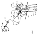
- FIG. 1 there is shown a perspective view of a preferred embodiment of the pump and delivery system 10 of the instant invention in the assembled status.
- the pump 100 includes a pistol-grip handle 101 which is, typically, ergonomically designed for comfort of the user.
- a housing 103 is mounted at the upper end of handle 101.
- a trigger 102 is pivotally mounted within housing 103 forward of the handle 101.
- trigger 102 is designed to comfortably interact with the front surface of handle 101.
- a pressure release valve actuator 104 is also pivotally mounted in the upper rear section of the housing 103.
- a piston 105 is mounted to the trigger 102 in the forward portion of the housing 103. Piston 105 is selectively moved in and out relative to housing 103 when the trigger 102 is manipulated by the user. The motion of the piston 105 activates the pump 100 as described infra.
- a conduit 200 comprises a hollow tube of any desired length fabricated of a flexible plastic material such as nylon. While the conduit 200 is, typically, fabricated of a transparent material, this is not a requirement of the invention.
- the conduit 200 is attached to the pump 100 at or within the housing 103 as described infra.
- the conduit 200 When included in the system, the conduit 200 is connected to the delivery unit 300 by means of the connector 400 for controlling the operation of the unit 300, as described infra.
- the delivery unit 300 includes a syringe 301 which is, typically, a hollow cylindrical body fabricated of material such as polycarbonate which may be transparent for ease in visualizing the contents thereof.
- the syringe is adapted to be connected to the pump directly or via conduit 200.
- Finger tabs 302 may be formed at one end of the syringe 301, if desired. The finger tabs (or any other suitable arrangement) may be utilized by the user to manipulate the syringe. A threaded connector (not visible in Figure 1 ) is provided at the end of syringe 301.
- Plunger 304 is disposed within the syringe 301.
- the plunger includes a plunger head 304 which has an outer diameter which is quite close to the inner diameter of the syringe to provide a close fit to enhance the force of the plunger on the contents of the syringe.
- a seal 305 is provided at the plunger head to provide a seal between the plunger and the syringe to prevent leakage around the head of the plunger 304.
- Connector 400 is rotatably mounted to conduit 200 to prevent twisting or kinking of conduit 200 when the connector 400 is threadedly attached to the delivery unit 300 is described infra.
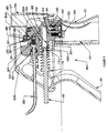
- FIG 2 there is shown a partially exploded view of the pump and delivery system 10 of the instant invention as shown in Figure 1 .
- the pump 100 includes a grip handle 101.
- the grip handle 101 includes the front portion 101A and the rear portion 101 B which are formed of a suitable material such as white abs.
- the front portion 101 A and the rear portion 101 B are, typically, separate components which snap together to form the grip handle 101.
- a suitable container 110 such as (but not limited to) a soft flexible waterproof bag is mounted it the grip handle 101.
- the container 110 stores a suitable incompressible liquid such as water or the like therein.
- the valve housing 103 mounted at the upper end of handle 101, includes opposing sides 103A and 103B which are formed of a suitable material such as white abs.
- the opposing sides 103A and 103B are, typically, separate components which snap together to form for the valve housing 103 which supports the trigger 102 and the valve mechanism body 500.
- the manual pressure release valve actuator 104, the piston 105 and the connection 201 for conduit 200 are supported by the valve mechanism body 500.
- a piston 105 is mounted to the trigger 102 in the forward portion of the housing 103. Piston 105 is selectively moved in and out relative to housing 103 when the trigger 102 is manipulated by the user. The motion of the piston 105 activates the pump 100 as described infra.
- Piston 105 is, selectively, driven into chamber 503 (in the valve mechanism body 500) by applying pressure to trigger 102 which rotates on pins 112 which are rotatably mounted in hub 113 formed on the interior of opposing sides 103A and 103B of housing 103.
- Spring 115 is mounted in the valve mechanism 500 and spring loads the piston 105 and the handle 102 to return to the position shown in Figures 1 , 2 and 3 .
- the chamber 503 communicates with check valves 504, 505 and 506 (described infra) to selectively transfer the liquid stored in container 110 to the conduit 200 which is connected to chamber 507 (which contains check valve 551).
- the manual pressure release valve actuator 104 is pivotally mounted in the support bracket 515 by pins 504A in slots 515A.
- a ball valve 580 is selectively released by rotation of the valve handle 104 around the pins 504A which opens a release valve in valve mechanism body 500.
- the end 306 of syringe 301 is threaded for attachment to the rotating air bleed connector 400 which is rotatably connected to the end of conduit 200.
- Conduit 200 comprises a hollow tube fabricated of a flexible plastic material such as nylon. While the conduit 200 is, typically, fabricated of a transparent material, this is not a requirement of the invention. The conduit 200 is attached to the body 500 within the housing 103 as described infra.
- the conduit 200 is connected to the delivery unit 300 by means of the connector 400 for controlling the operation of the unit 300, as described infra.
- the delivery unit 300 includes a hollow syringe 301 which is, typically, fabricated of transparent material for ease in visualizing the contents thereof. Finger tabs 302 are formed at one end of the syringe 301. The finger tabs are utilized by the user to manipulate the syringe.
- Plunger 303 is disposed within the syringe 301.
- the plunger includes a plunger head 304 which has an outer diameter which is quite close to the inner diameter of the syringe to provide a close fit to enhance the force of the plunger on the contents of the syringe.
- a seal 305 similar to an O-ring or the like is provided at the plunger head to provide a seal between the plunger and the syringe to prevent leakage around the plunger head 304.
- Connector 400 is rotatably mounted to conduit 200 to prevent twisting or kinking of conduit 200 when the connector 400 is threadedly attached to the delivery unit 300.
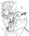
- FIG. 3 there is shown a partially sectional, partially broken away view of the assembled control valve mechanism body 500 of the manual pump 100 as shown in Figure 2 .
- the trigger 102 is pivotally mounted to the inside of housing 103.
- the piston 105 passes through an aperture in the mid portion of trigger 102 and into cavity 513 in chamber 503.
- the inner end 105A of piston 105 includes a groove therearound for receiving a suitable seal 116 such as an O-ring or the like.
- An appropriate abutment 156 (or shoulder) engages the inner surface of the trigger 102 and one end of spring 115.
- the spring 115 in this embodiment a coil spring, surrounds the inner portion of piston 105 and the outer surface of chamber 503. The spring is interposed between abutment 156 and the shoulder 503A of chamber 503 to spring-load the piston 105 and the trigger 102 in the outwardly position (i.e., to the left in Figure 3 ).
- An exit chamber 507 is connected to and communicates with conduit 200.
- a check valve 551 is provided in chamber 507 to control fluid flow from chamber 513 to chamber 507 via channel 552.
- Check value 551 includes a ball 562 which is spring loaded by spring 563 in check valve 551 to seat against the inlet from channel 552 which is defined by an O-ring 553 or similar seal set.
- chamber 555 is connected to and communicates from chamber 513 with container 110 via channel 554.
- Check valve 504 is provided in chamber 555 to control fluid flow between chamber 513 and container 110.
- the trigger 102 is actuated by pulling toward the handle 101.
- the trigger pivots about the pins 112 in the hubs 113.
- the trigger 102 bears upon the shoulder 156 of piston 105 and pushes the piston inwardly against spring 115.
- piston 105 Upon the next activation of trigger 102, piston 105 again forces the contents (now liquid) from chamber 513 into channel 552, through check valve 551 and into conduit 200 to apply pressure at the end thereof.
- Relief valve 560 is connected between pressure chamber 513 and the container (reservoir) 110.
- the plug 561 is urged by spring 562 to block the outlet orifice 514 from chamber 513.
- the pressure release mechanism including actuator 104 is mounted at the upper rear portion of body 500.
- pins 504A on the actuator 104 are pivotally mounted in slots 575 in the pivot support which is formed about the chamber 506.
- Spring 577 is located in the pivot support 576, typically in a recess 578.
- Spring 577 is disposed behind the pivot pins 504 and slots 575 as so to apply an upward (closing) force in the actuator 104.
- the actuator 104 includes, typically, an opening 579 in the lower surface of the forward section relative to the pivot pins 504.
- the opening 579 is adapted to provide a seat for the check ball 580 as well as a passage for a set screw 581 which is adjustable in the passage relative to the actuator 104.
- the check ball 580 is disposed in a recess 582 in the support 515 which recess communicates with chamber 507.
- the actuator 104 In operation, when a process of pumping has been terminated, the actuator 104 is pressed at the lower back end thereof. The actuator 104 pivots around pins 504 (against the force of spring 577). The check ball 580 is free to move upwardly (within the confines of recess 582) as determined by set screw 581, thereby unblocking the communication with chamber 507. The pressurized fluid (liquid) applied to chamber 507 via conduit 552 is immediately released through unblocked recess 582 wherein pressure in conduit 200 is immediately released and possible "run-on" at the output of the system is prevented.
- spring 577 pivots the actuator to the closed position which returns check ball 580 to the blocking position in recess 582 where it remains under pressure of the actuator as determined by spring 577.
- the set screw 581 can provide "fine tuning" of the closure operation by check ball 580.
- FIG. 4 there is shown an enlarged, exploded view of a portion of the control valve section of body 500 of the system of the instant invention shown in Figures 2 and 3 .
- the pins 112 of trigger 102 are pivotally mounted to hubs 113 on the inside of housing 103 (sides 103A and 103B, respectively).
- the piston 105 passes through an aperture in the mid portion of trigger 102 (see Figure 3 ) and into cavity 513 in chamber 503.
- the inner end 105A of piston 105 includes a groove therearound for receiving a suitable seal 116 such as an O-ring or the like.
- An appropriate abutment (or shoulder) 156 (see Figure 3 ) engages the inner surface of the trigger 102 and one end of spring 115 which surrounds the inner portion of piston 105 and the outer surface of chamber 503.
- the spring is interposed between abutment 156 and the shoulder 503A of chamber 503 to spring-load the piston 105 and the trigger 102 in the outwardly position (i.e., to the left in Figure 4 ).
- the exit chamber 507 is connected to and communicates with conduit 200.
- a check valve 551 is provided in chamber 507 to control fluid flow from chamber 513 to chamber 507 via channel 552.
- Check value 551 includes a ball 562 which is spring loaded by spring 601 in check valve 551 to seat against the inlet from channel 552 which is defined by an O-ring 553 or similar seal set (see Figure 3 ).
- chamber 555 is connected to and communicates with container 110 via channel 554.
- Check valve 504 is provided in chamber 555 to control fluid flow between chamber 513 and container 110.
- Chamber 560 is connected to and communicates with chamber 513 and container 110.
- the trigger 102 is actuated by pulling toward the handle 101.
- the trigger pivots about the pins 112 in the hubs 113.
- the trigger 102 bears upon the abutment 156 of piston 105 and pushes the piston inwardly against spring 115.
- piston 105 When trigger 102 is activated again, piston 105 again forces the contents (now liquids) from chamber 513 into channel 552, check valve 551 and into conduit 200 to apply pressure at the end thereof.
- Relief valve 560 is connected between pressure chamber 513 and the reservoir 110.
- the plug 561 is urged by spring 562 to block the outlet orifice 514 from chamber 513.
- the pressure release mechanism including actuator 104 is mounted at the upper rear portion of body 500.
- pins 504 on the actuator 104 are pivotally mounted in slots 575 in the pivot support 576 which is formed about the chamber 506.
- Spring 577 is located in the pivot support 576, typically in a recess 578.
- Spring 577 is disposed behind the pivot pins 504 and slots 575 as so to apply an upward (closing) force in the actuator 104.
- the actuator 104 includes, typically, an opening 579 in the lower surface thereof in the forward section relativ eto the pivot pins 504.
- the opening 579 is adapted to provide a seat for the check ball 580 as well as a passage for a set screw 581 which is adjustable in the passage relative to the actuator 504.
- the check ball 580 is disposed in a recess 582 (shown dashed) in the support 515 which recess communicates with chamber 507.
- the actuator 104 When a pumping process has been terminated, the actuator 104 is pressed at the lower back end thereof. The actuator 104 pivots around pins 504 against the force of spring 577, and the check ball 580 is free to move upwardly within recess 582 (as determined by set screw 581) thereby unblocking the communication with chamber 507. The pressurized liquid applied to chamber 507 via conduit 552 is immediately released through unblocked recess 582 wherein pressure in conduit 200 is immediately released an possible "run-on" at the output of the system is prevented.
- spring 577 pivots the actuator to the closed position which returns check ball 580 to the blocking position in recess 582 where it remains under pressure of the actuator as determined by spring 577.
- the set screw 581 can provide "fine tuning" of the closure operation by check ball 580.
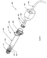
- FIG. 5 there is shown an enlarged, partially exploded view of the connections of the syringe and delivery system of the instant invention.
- the conduit 200 is passed through an opening in a central support structure 401 in connector housing 400 and joined to a threaded connector 402 by an O-ring 403 and a ferrule 404.
- the interior surface of the central support structure 401 is threaded to selectively engage the outer threaded surface of connector 402 and to capture O-ring 403 to provide an internal seal.
- the inner surface of the central support structure includes a sloped surface which engages the ferrule 404 and a shoulder which engages set screw 402 for proper seating of the seal.
- the conduit is passed through the central support structure 401, the ferrule 404, the O-ring 403 and the set screw 402.
- the set screw 402 is threaded into the threaded portion of support structure 401 to seal the ferrule and to compress the O-ring to secure the conduit in the housing 400 and to provide a seal therearound.
- the housing 401 is also threadedly engaged with the threaded end 405 of syringe 301.
- the threaded end may be attached to or integrally formed with the syringe body 301.
- the finger tabs 302 may be formed with the syringe body, if so desried.
- a plunger 304 fits snugly within the syringe body 301 and is attached to a seal 305 which prevents leakage around the plunger.
- the outlet 310 of the syringe is a hollow cylinder or tube which communicates with the interior of the syringe.
- a conventional Luer connector 311 is formed at the end of the syringe and surrounds the outlet 310.
- the outlet 310 and the Luer connector 311 are adapted to engage, inter alia, a conventional Trocar instrument (not shown).
- FIG. 6 there is shown a cross-sectional view of one embodiment of the connections of the syringe 301 and delivery system of the instant invention as shown in Figure 5 .
- the conduit 200 is passed through an opening 410 which is provided in a central support structure 401 portion of connector housing 400.
- Conduit 200 is joined to a threaded connector (or set screw) 402 by an O-ring 403 and a ferrule 404.
- a portion of the interior surface of the central support structure 401 is threaded to selectively engage the outer threaded surface of connector 402.
- a portion of the interior surface of support structure 401 is sloped to engage ferrule 404 to capture 0-ring 403 to provide an internal seal for the connector 400. That is, the inner surface of the central support structure 401 includes a sloped surface 406 which engages the sloped surface of ferrule 404 and a shoulder 407 which engages set screw 402 for proper seating of the seal.
- the conduit 200 is passed through the central support structure 401, the ferrule 404, the O-ring 403 and the set screw 402.
- the set screw 402 is threaded into the threaded portion of support structure 401 to seal the ferrule and to compress the O-ring to secure the conduit in the housing 400 and to provide a seal therearound.
- the housing 401 is also threadedly engaged with the threaded end 405 of syringe 300.
- the threaded end may be attached to or integrally formed with the syringe body 301.
- the connector 700 includes connector housing 701 which, typically, comprises a knurled or faceted surface portion 702 and a cylindrical end 703. These components are deemed desirable but can be of other shapes, if so desired.
- the interior surface 702A of the faceted portion 702 of the connector is threaded to receive and engage the threaded connector on the syringe 300.
- the interior surface of the cylindrical end 703 is also threaded to receive and engage the set screw 704 which is selectively interacted with the connector housing 701.
- the set screw 704 includes a recess 704A at the inner end thereof as well as a tapered surface 704B surrounding the axial aperture through the recess 704A.
- the conduit 200 is inserted into the cylindrical end 703 of housing 701 via aperture 705 which is, preferably, a snug fit.
- a suitable O-ring 706 is snugly engaged with conduit 200 and mounted in a receiving groove 707 in the interior end wall of housing 701.
- the O-ring 706 is a double O-ring for secure sealing around the conduit 200.
- the sleeve or ferrule 708 includes a tapered or conic end as well as a flat or washer-like end.
- the flat end abuts against the interior surface of cylindrical end 703 and retains O-ring 706 in the groove 707 when the set screw 704 is put in place and the tapered surface 704B wedges against the tapered or conic surface of the ferrule 707.
- connector 400 or 700 can be attached to the syringe.
- the connector 400 or 700 is capable of rotating around the conduit 200 without twisting or "kinking" the conduit 200 while maintaining a secure seal.
- the connector 400 or 700 bleeds off any air which is present within the syringe when the system is connected together.
- the trapped air if any, gathers inside the space inside the set screw 402 or 704, respectively. This air can escape around the conduit 200 as sealed by the O-ring 403 or 706, respectively.
- the connector 400 or 700 seals against the liquid which is in the syringe 300 (i.e., the drive liquid) and prevents leakage at this juncture as discussed.
- a plunger 304 fits snugly within the syringe body 301 and is attached to a seal 305 which prevents leakage around the plunger. (See Figures 1 and 5 )
- the outlet 310 of the syringe is a hollow cylinder or tube which communicates with the interior of the syringe.
- a conventional threaded Luer connector 311 is formed at the end of the syringe and surrounds the outlet 310 as shown in Figure 5 .
- the pump mechanism 100 is assembled as shown in Figures 1 and 2 including a liquid such as a saline solution, purified water or the like container 110.
- the viscous material is placed into the syringe 301 in a suitable manner (see infra).
- the outlet connector 311 is connected to the application site.
- the outlet connector 311 is a Luer connector which is threaded to the end of a Trocar instrument which has been inserted into place.
- the plunger 304 and seal 305 are placed into the syringe 301 in proximity to the viscous material.
- the inlet connector 306 of the syringe is threadedly attached to the coupler housing 400 (again a Luer fitting can be utilized).
- the apparatus is now assembled and ready for operation.
- liquid is drawn out of container 110 and forced through conduit 200 via the connector 400 or 700 into syringe 301 to exert force against plunger 304.
- the plunger 304 (with seal 305) is forced through the syringe 301, the viscous material in the syringe is forced out through the outlet connector 310 into the operational tool or to the application site.
- valve portion 500 permit the liquid to flow into the conduit 200 under controlled pressure but not in the reverse direction.
- the pressure release valve 104 is activated to immediately relieve the pressure on the liquid in the conduit 200 and, thus, on the viscous material in the syringe. This quick release of pressure prevents "run-on" of viscous material from syringe 301 into the application site.
Description
- 1. Field of the Invention. The system is utilized in a procedure wherein a viscous material is injected into a body, in general, and to such a system wherein the injection is controlled by a remote hydraulic pressure pump, in particular.
- 2. Prior Art. There are certain known surgical procedures where a viscous material is injected into a body (or body part) while the injection of the material is monitored with a fluoroscope or X-ray type device. The material being injected is, typically, a thick paste or putty-like material which is difficult to force through the small tube extending from the remote syringe devices. In these procedures, the individual who activates the system, typically a surgeon, receives repetitive and prolonged exposure to radiation from the monitoring device.
- Currently, several techniques are used to lower the radiation exposure of the surgeon (or other facilitator of similar procedures). In one such technique lead lined gloves are worn by the operator to reduce the effect of the radiation. However, the lead-lined gloves are heavy and clumsy to use and still require the user to be close enough to the field to be subjected to radiation scatter.
- In another technique, a remote syringe body expels the fluid through a long tube which extends into the radiation field. This device leaves the syringe at the original location and uses a secondary fluid to exert the force into the radiation field. However, in the known devices the physical requirements on the user are extreme and the pressures required cause numerous failures.
-
FR-A-1 548 575 -
US-A-5,411,180 discloses a self-contained dispensing mechanism which includes a main body joined to a reservoir, cylinder and piston structure on the main body and a stop assembly for securing containers on said main body. A pump is provided in the main body for pumping liquid from the reservoir to the cylinder to actuate the piston therein. A piston rod, secured to the piston and movable therewith actuates push rods with push ends for dispensing viscous material from the containers. The push ends are adjustably secured on the push rods for accommodating different sizes of containers. - The instant invention is defined in claim 1.
- The system of the instant invention consists of a hand-piece with a lever operated hydraulic pump and a fluid reservoir, a connecting tube and a remote connector which will seal to a syringe body. The pump expels the fluid from the fluid reservoir through the connecting tube into the top of the syringe where the fluid presses on the syringe plunger thereby expeiling the material contained in the primary chamber of the syringe therefrom.
- By using a low viscosity, inexpensive, secondary incompressible fluid in the connecting tube, the force required to expel material from the syringe can be reduced and the volume of injection fluid, which is typically expensive, can be reduced. The use of a small hand pump allows the device to be lightweight, compact and ergonomically designed.
-
-
Figure 1 is a perspective view of one embodiment of the manual pump and delivery system of the instant invention. -
Figure 2 is a partially broken away, exploded view of one embodiment of the manual pump and delivery system of the instant invention. -
Figure 3 is a sectional view of the control valve section of the manual pump part of the instant invention. -
Figure 4 is an enlarged, exploded perspective view of the control valve section of the manual pump part of the instant invention as shown inFigure 3 . -
Figure 5 is an enlarged, partially exploded view of the syringe and delivery portion of the instant invention. -
Figure 6 is a cross-sectional view of the syringe and delivery portion of the instant invention. -
Figure 7 is a partially broken away, partially cross-sectional view of an alternative connector construction. - Referring now to
Figure 1 , there is shown a perspective view of a preferred embodiment of the pump anddelivery system 10 of the instant invention in the assembled status. - The
pump 100 includes a pistol-grip handle 101 which is, typically, ergonomically designed for comfort of the user. Ahousing 103 is mounted at the upper end ofhandle 101. Atrigger 102 is pivotally mounted withinhousing 103 forward of thehandle 101. Typically,trigger 102 is designed to comfortably interact with the front surface ofhandle 101. - A pressure
release valve actuator 104 is also pivotally mounted in the upper rear section of thehousing 103. - A
piston 105 is mounted to thetrigger 102 in the forward portion of thehousing 103. Piston 105 is selectively moved in and out relative tohousing 103 when thetrigger 102 is manipulated by the user. The motion of thepiston 105 activates thepump 100 as described infra. - In a preferred embodiment, a
conduit 200 comprises a hollow tube of any desired length fabricated of a flexible plastic material such as nylon. While theconduit 200 is, typically, fabricated of a transparent material, this is not a requirement of the invention. Theconduit 200 is attached to thepump 100 at or within thehousing 103 as described infra. - When included in the system, the
conduit 200 is connected to thedelivery unit 300 by means of theconnector 400 for controlling the operation of theunit 300, as described infra. - The
delivery unit 300 includes asyringe 301 which is, typically, a hollow cylindrical body fabricated of material such as polycarbonate which may be transparent for ease in visualizing the contents thereof. The syringe is adapted to be connected to the pump directly or viaconduit 200. -
Finger tabs 302 may be formed at one end of thesyringe 301, if desired. The finger tabs (or any other suitable arrangement) may be utilized by the user to manipulate the syringe. A threaded connector (not visible inFigure 1 ) is provided at the end ofsyringe 301. - Plunger 304 is disposed within the
syringe 301. The plunger includes aplunger head 304 which has an outer diameter which is quite close to the inner diameter of the syringe to provide a close fit to enhance the force of the plunger on the contents of the syringe. Aseal 305, similar to an O-ring or the like, is provided at the plunger head to provide a seal between the plunger and the syringe to prevent leakage around the head of theplunger 304. -
Connector 400 is rotatably mounted to conduit 200 to prevent twisting or kinking ofconduit 200 when theconnector 400 is threadedly attached to thedelivery unit 300 is described infra. - Referring now to
Figure 2 , there is shown a partially exploded view of the pump anddelivery system 10 of the instant invention as shown inFigure 1 . - As noted, the
pump 100 includes agrip handle 101. In particular, thegrip handle 101 includes thefront portion 101A and therear portion 101 B which are formed of a suitable material such as white abs. Thefront portion 101 A and therear portion 101 B are, typically, separate components which snap together to form thegrip handle 101. - A
suitable container 110 such as (but not limited to) a soft flexible waterproof bag is mounted it thegrip handle 101. Thecontainer 110 stores a suitable incompressible liquid such as water or the like therein. - The
valve housing 103, mounted at the upper end ofhandle 101, includes opposingsides sides valve housing 103 which supports thetrigger 102 and thevalve mechanism body 500. The manual pressurerelease valve actuator 104, thepiston 105 and theconnection 201 forconduit 200 are supported by thevalve mechanism body 500. - A
piston 105 is mounted to thetrigger 102 in the forward portion of thehousing 103.Piston 105 is selectively moved in and out relative tohousing 103 when thetrigger 102 is manipulated by the user. The motion of thepiston 105 activates thepump 100 as described infra. -
Piston 105 is, selectively, driven into chamber 503 (in the valve mechanism body 500) by applying pressure to trigger 102 which rotates onpins 112 which are rotatably mounted inhub 113 formed on the interior of opposingsides housing 103.Spring 115 is mounted in thevalve mechanism 500 and spring loads thepiston 105 and thehandle 102 to return to the position shown inFigures 1 ,2 and3 . - The
chamber 503 communicates withcheck valves container 110 to theconduit 200 which is connected to chamber 507 (which contains check valve 551). - The manual pressure
release valve actuator 104 is pivotally mounted in thesupport bracket 515 bypins 504A in slots 515A. Aball valve 580 is selectively released by rotation of the valve handle 104 around thepins 504A which opens a release valve invalve mechanism body 500. - The
end 306 ofsyringe 301 is threaded for attachment to the rotatingair bleed connector 400 which is rotatably connected to the end ofconduit 200. -
Conduit 200 comprises a hollow tube fabricated of a flexible plastic material such as nylon. While theconduit 200 is, typically, fabricated of a transparent material, this is not a requirement of the invention. Theconduit 200 is attached to thebody 500 within thehousing 103 as described infra. - The
conduit 200 is connected to thedelivery unit 300 by means of theconnector 400 for controlling the operation of theunit 300, as described infra. - The
delivery unit 300 includes ahollow syringe 301 which is, typically, fabricated of transparent material for ease in visualizing the contents thereof.Finger tabs 302 are formed at one end of thesyringe 301. The finger tabs are utilized by the user to manipulate the syringe. - Plunger 303 is disposed within the
syringe 301. The plunger includes aplunger head 304 which has an outer diameter which is quite close to the inner diameter of the syringe to provide a close fit to enhance the force of the plunger on the contents of the syringe. Aseal 305 similar to an O-ring or the like is provided at the plunger head to provide a seal between the plunger and the syringe to prevent leakage around theplunger head 304. -
Connector 400 is rotatably mounted toconduit 200 to prevent twisting or kinking ofconduit 200 when theconnector 400 is threadedly attached to thedelivery unit 300. - Referring now to
Figure 3 , there is shown a partially sectional, partially broken away view of the assembled controlvalve mechanism body 500 of themanual pump 100 as shown inFigure 2 . - The
trigger 102 is pivotally mounted to the inside ofhousing 103. Thepiston 105 passes through an aperture in the mid portion oftrigger 102 and into cavity 513 inchamber 503. - The
inner end 105A ofpiston 105 includes a groove therearound for receiving asuitable seal 116 such as an O-ring or the like. An appropriate abutment 156 (or shoulder) engages the inner surface of thetrigger 102 and one end ofspring 115. Thespring 115, in this embodiment a coil spring, surrounds the inner portion ofpiston 105 and the outer surface ofchamber 503. The spring is interposed betweenabutment 156 and theshoulder 503A ofchamber 503 to spring-load thepiston 105 and thetrigger 102 in the outwardly position (i.e., to the left inFigure 3 ). - An
exit chamber 507 is connected to and communicates withconduit 200. Acheck valve 551 is provided inchamber 507 to control fluid flow from chamber 513 tochamber 507 viachannel 552. - Check
value 551 includes aball 562 which is spring loaded byspring 563 incheck valve 551 to seat against the inlet fromchannel 552 which is defined by an O-ring 553 or similar seal set. - In addition,
chamber 555 is connected to and communicates from chamber 513 withcontainer 110 viachannel 554.Check valve 504 is provided inchamber 555 to control fluid flow between chamber 513 andcontainer 110. - In operation, the
trigger 102 is actuated by pulling toward thehandle 101. The trigger pivots about thepins 112 in thehubs 113. In addition, thetrigger 102 bears upon theshoulder 156 ofpiston 105 and pushes the piston inwardly againstspring 115. - As
piston 105 moves inwardly in chamber 513, the contents of chamber 513 (initially, air) is compressed and forces checkvalve 504 to remain closed while forcingcheck valve 551 open. Thus, the contents of chamber 513 passes throughchannel 552 andchamber 507 intoconduit 200. - When the
trigger 102 is released, thepiston 105 is withdrawn from chamber 513 under force ofspring 115. This action creates a vacuum in chamber 513 which draws the fluid fromcontainer 110 viacheck valve 504 andchamber 555. - Upon the next activation of
trigger 102,piston 105 again forces the contents (now liquid) from chamber 513 intochannel 552, throughcheck valve 551 and intoconduit 200 to apply pressure at the end thereof. -
Relief valve 560 is connected between pressure chamber 513 and the container (reservoir) 110. Theplug 561 is urged byspring 562 to block theoutlet orifice 514 from chamber 513. - However, when the pressure in chamber 513 exceeds a predetermined level, the
plug 561 is forced downwardly so that the contents of chamber 513 can flow throughrelief valve 560 intocontainer 110. Thus, the pressure exerted on and by the contents of chamber 513 is limited and an over pressure condition in the system is avoided. - Similarly, the pressure release
mechanism including actuator 104 is mounted at the upper rear portion ofbody 500. In particular, pins 504A on theactuator 104 are pivotally mounted inslots 575 in the pivot support which is formed about thechamber 506.Spring 577 is located in the pivot support 576, typically in a recess 578.Spring 577 is disposed behind the pivot pins 504 andslots 575 as so to apply an upward (closing) force in theactuator 104. Theactuator 104 includes, typically, anopening 579 in the lower surface of the forward section relative to the pivot pins 504. Theopening 579 is adapted to provide a seat for thecheck ball 580 as well as a passage for a set screw 581 which is adjustable in the passage relative to theactuator 104. - The
check ball 580 is disposed in arecess 582 in thesupport 515 which recess communicates withchamber 507. - In operation, when a process of pumping has been terminated, the
actuator 104 is pressed at the lower back end thereof. Theactuator 104 pivots around pins 504 (against the force of spring 577). Thecheck ball 580 is free to move upwardly (within the confines of recess 582) as determined by set screw 581, thereby unblocking the communication withchamber 507. The pressurized fluid (liquid) applied tochamber 507 viaconduit 552 is immediately released through unblockedrecess 582 wherein pressure inconduit 200 is immediately released and possible "run-on" at the output of the system is prevented. - When actuator 104 is released,
spring 577 pivots the actuator to the closed position which returnscheck ball 580 to the blocking position inrecess 582 where it remains under pressure of the actuator as determined byspring 577. The set screw 581 can provide "fine tuning" of the closure operation bycheck ball 580. - Referring now to
Figure 4 , there is shown an enlarged, exploded view of a portion of the control valve section ofbody 500 of the system of the instant invention shown inFigures 2 and3 . - The
pins 112 oftrigger 102 are pivotally mounted tohubs 113 on the inside of housing 103 (sides piston 105 passes through an aperture in the mid portion of trigger 102 (seeFigure 3 ) and into cavity 513 inchamber 503. - The
inner end 105A ofpiston 105 includes a groove therearound for receiving asuitable seal 116 such as an O-ring or the like. An appropriate abutment (or shoulder) 156 (seeFigure 3 ) engages the inner surface of thetrigger 102 and one end ofspring 115 which surrounds the inner portion ofpiston 105 and the outer surface ofchamber 503. The spring is interposed betweenabutment 156 and theshoulder 503A ofchamber 503 to spring-load thepiston 105 and thetrigger 102 in the outwardly position (i.e., to the left inFigure 4 ). - The
exit chamber 507 is connected to and communicates withconduit 200. Acheck valve 551 is provided inchamber 507 to control fluid flow from chamber 513 tochamber 507 viachannel 552. - Check
value 551 includes aball 562 which is spring loaded byspring 601 incheck valve 551 to seat against the inlet fromchannel 552 which is defined by an O-ring 553 or similar seal set (seeFigure 3 ). - In addition,
chamber 555 is connected to and communicates withcontainer 110 viachannel 554.Check valve 504 is provided inchamber 555 to control fluid flow between chamber 513 andcontainer 110. -
Chamber 560 is connected to and communicates with chamber 513 andcontainer 110. - Once again, in operation, the
trigger 102 is actuated by pulling toward thehandle 101. The trigger pivots about thepins 112 in thehubs 113. In addition, thetrigger 102 bears upon theabutment 156 ofpiston 105 and pushes the piston inwardly againstspring 115. - As
piston 105 moves inwardly in chamber 513, the contents of chamber 513 forces checkvalve 504 to remain closed while forcingcheck valve 551 open. Thus, the contents of chamber 513 passes throughchannel 552 andchamber 507 intoconduit 200. - When the
piston 105 is withdrawn from chamber 513, thetrigger 102 is released, and creates a vacuum therein which draws the fluid fromcontainer 110 viacheck valve 504. - When
trigger 102 is activated again,piston 105 again forces the contents (now liquids) from chamber 513 intochannel 552,check valve 551 and intoconduit 200 to apply pressure at the end thereof. -
Relief valve 560 is connected between pressure chamber 513 and thereservoir 110. Theplug 561 is urged byspring 562 to block theoutlet orifice 514 from chamber 513. - Thus, when the pressure in chamber 513 exceeds a predetermined level, the
plug 561 is forced downwardly so that the contents of chamber 513 can flow throughrelief valve 560 intocontainer 110. Thus, the pressure exerted on and by the contents of chamber 513 is limited and an over pressure condition in the system is avoided. - Similarly, the pressure release
mechanism including actuator 104 is mounted at the upper rear portion ofbody 500. In particular, pins 504 on theactuator 104 are pivotally mounted inslots 575 in the pivot support 576 which is formed about thechamber 506.Spring 577 is located in the pivot support 576, typically in a recess 578.Spring 577 is disposed behind the pivot pins 504 andslots 575 as so to apply an upward (closing) force in theactuator 104. Theactuator 104 includes, typically, anopening 579 in the lower surface thereof in the forward section relativ eto the pivot pins 504. Theopening 579 is adapted to provide a seat for thecheck ball 580 as well as a passage for a set screw 581 which is adjustable in the passage relative to theactuator 504. - The
check ball 580 is disposed in a recess 582 (shown dashed) in thesupport 515 which recess communicates withchamber 507. - When a pumping process has been terminated, the
actuator 104 is pressed at the lower back end thereof. Theactuator 104 pivots aroundpins 504 against the force ofspring 577, and thecheck ball 580 is free to move upwardly within recess 582 (as determined by set screw 581) thereby unblocking the communication withchamber 507. The pressurized liquid applied tochamber 507 viaconduit 552 is immediately released through unblockedrecess 582 wherein pressure inconduit 200 is immediately released an possible "run-on" at the output of the system is prevented. - When actuator 104 is released,
spring 577 pivots the actuator to the closed position which returnscheck ball 580 to the blocking position inrecess 582 where it remains under pressure of the actuator as determined byspring 577. The set screw 581 can provide "fine tuning" of the closure operation bycheck ball 580. - Referring now to
Figure 5 , there is shown an enlarged, partially exploded view of the connections of the syringe and delivery system of the instant invention. Theconduit 200 is passed through an opening in acentral support structure 401 inconnector housing 400 and joined to a threadedconnector 402 by an O-ring 403 and aferrule 404. The interior surface of thecentral support structure 401 is threaded to selectively engage the outer threaded surface ofconnector 402 and to capture O-ring 403 to provide an internal seal. - For control purposes, the inner surface of the central support structure includes a sloped surface which engages the
ferrule 404 and a shoulder which engages setscrew 402 for proper seating of the seal. - In assembly, the conduit is passed through the
central support structure 401, theferrule 404, the O-ring 403 and theset screw 402. Theset screw 402 is threaded into the threaded portion ofsupport structure 401 to seal the ferrule and to compress the O-ring to secure the conduit in thehousing 400 and to provide a seal therearound. - The
housing 401 is also threadedly engaged with the threadedend 405 ofsyringe 301. The threaded end may be attached to or integrally formed with thesyringe body 301. (Thefinger tabs 302 may be formed with the syringe body, if so desried.) - A
plunger 304 fits snugly within thesyringe body 301 and is attached to aseal 305 which prevents leakage around the plunger. - The
outlet 310 of the syringe is a hollow cylinder or tube which communicates with the interior of the syringe. Aconventional Luer connector 311 is formed at the end of the syringe and surrounds theoutlet 310. Theoutlet 310 and theLuer connector 311 are adapted to engage, inter alia, a conventional Trocar instrument (not shown). - Referring now to
Figure 6 , there is shown a cross-sectional view of one embodiment of the connections of thesyringe 301 and delivery system of the instant invention as shown inFigure 5 . Theconduit 200 is passed through anopening 410 which is provided in acentral support structure 401 portion ofconnector housing 400.Conduit 200 is joined to a threaded connector (or set screw) 402 by an O-ring 403 and aferrule 404. A portion of the interior surface of thecentral support structure 401 is threaded to selectively engage the outer threaded surface ofconnector 402. A portion of the interior surface ofsupport structure 401 is sloped to engageferrule 404 to capture 0-ring 403 to provide an internal seal for theconnector 400. That is, the inner surface of thecentral support structure 401 includes asloped surface 406 which engages the sloped surface offerrule 404 and ashoulder 407 which engages setscrew 402 for proper seating of the seal. - In assembly, the
conduit 200 is passed through thecentral support structure 401, theferrule 404, the O-ring 403 and theset screw 402. Theset screw 402 is threaded into the threaded portion ofsupport structure 401 to seal the ferrule and to compress the O-ring to secure the conduit in thehousing 400 and to provide a seal therearound. - The
housing 401 is also threadedly engaged with the threadedend 405 ofsyringe 300. The threaded end may be attached to or integrally formed with thesyringe body 301. - Referring now to
Figure 7 , there is shown a partially broken away, partially cross-sectional view of an alternative construction of theconnector 700 of the instant system. Theconnector 700 includesconnector housing 701 which, typically, comprises a knurled orfaceted surface portion 702 and a cylindrical end 703. These components are deemed desirable but can be of other shapes, if so desired. - The
interior surface 702A of thefaceted portion 702 of the connector is threaded to receive and engage the threaded connector on thesyringe 300. - The interior surface of the cylindrical end 703 is also threaded to receive and engage the
set screw 704 which is selectively interacted with theconnector housing 701. Theset screw 704 includes arecess 704A at the inner end thereof as well as atapered surface 704B surrounding the axial aperture through therecess 704A. - In assembly, the
conduit 200 is inserted into the cylindrical end 703 ofhousing 701 viaaperture 705 which is, preferably, a snug fit. - A suitable O-
ring 706 is snugly engaged withconduit 200 and mounted in a receivinggroove 707 in the interior end wall ofhousing 701. In a preferred embodiment, the O-ring 706 is a double O-ring for secure sealing around theconduit 200. - In this embodiment, the sleeve or
ferrule 708 includes a tapered or conic end as well as a flat or washer-like end. The flat end abuts against the interior surface of cylindrical end 703 and retains O-ring 706 in thegroove 707 when theset screw 704 is put in place and thetapered surface 704B wedges against the tapered or conic surface of theferrule 707. - Thus, either
connector 400 or 700 (or any suitable replacement) can be attached to the syringe. There are several advantages of the connector designs described above. For example, theconnector conduit 200 without twisting or "kinking" theconduit 200 while maintaining a secure seal. - The
connector set screw conduit 200 as sealed by the O-ring - When the air has escaped, the
connector - That is, a
plunger 304 fits snugly within thesyringe body 301 and is attached to aseal 305 which prevents leakage around the plunger. (SeeFigures 1 and5 ) - The
outlet 310 of the syringe is a hollow cylinder or tube which communicates with the interior of the syringe. A conventional threadedLuer connector 311 is formed at the end of the syringe and surrounds theoutlet 310 as shown inFigure 5 . - In a typical operation, the
pump mechanism 100 is assembled as shown inFigures 1 and2 including a liquid such as a saline solution, purified water or thelike container 110. - Substantially concurrently, the viscous material is placed into the
syringe 301 in a suitable manner (see infra). Theoutlet connector 311 is connected to the application site. In one operation, theoutlet connector 311 is a Luer connector which is threaded to the end of a Trocar instrument which has been inserted into place. Theplunger 304 and seal 305 are placed into thesyringe 301 in proximity to the viscous material. Theinlet connector 306 of the syringe is threadedly attached to the coupler housing 400 (again a Luer fitting can be utilized). - The apparatus is now assembled and ready for operation. By activating the
trigger 102, liquid is drawn out ofcontainer 110 and forced throughconduit 200 via theconnector syringe 301 to exert force againstplunger 304. As the plunger 304 (with seal 305) is forced through thesyringe 301, the viscous material in the syringe is forced out through theoutlet connector 310 into the operational tool or to the application site. - As described supra, the several check valves in the
valve portion 500 permit the liquid to flow into theconduit 200 under controlled pressure but not in the reverse direction. - When the application of the viscous material is completed, the
pressure release valve 104 is activated to immediately relieve the pressure on the liquid in theconduit 200 and, thus, on the viscous material in the syringe. This quick release of pressure prevents "run-on" of viscous material fromsyringe 301 into the application site. - Thus, there is shown and described a unique design and concept of a manual pump mechanism and delivery system for viscous materials. While this description is directed to particular embodiments, it is understood that those skilled in the art may conceive modifications and/or variations to the specific embodiments shown and described herein. Any such modifications or variations which within the purview of this description are intended to be included therein as well. It is understood that the description herein is intended to be illustrative only and is not intended to be limitative. Rather, the scope of the invention described herein is limited only by the claims appended hereto.
Claims (14)
- A hand-held pumping system (10), comprising:a source of low viscosity incompressible fluid (110) for selective pressurization,handle means (101) for supporting said source of fluid,housing means (103) formed with said handle means (101),a hydraulic.hand pump mechanism for pressurizing fluid from said source of fluid,an elongated, flexible conduit (200) for selectively carrying said fluid from said hand pump mechanism when said fluid is pressurized,a container (301) of a viscous material connected to said conduit (200) to receive pressurized fluid from said conduit (200) to selectively force said viscous material from said container, anda manual pressure release mechanism (104) connected to said housing means for selectively relieving pressure from said fluid in said conduit by releasing at least a portion of said fluid to the outside of the conduit.
- The system recited in claim 1, including:valve means (500) mounted in said housing means (103) for controlling the movement of said fluid from said source of fluid (110) through said conduit (200), andconnector means (400) for connecting said conduit (200) to said container (301).
- The system recited in claim 2 wherein said connector means (400) includes:a hollow housing (401) for receiving an end of said conduit (200) through an axial opening therein,a set screw (402) threadedly engaged with the interior of said hollow housing (401) and surrounding said end of said conduit (200),seal means (403) surrounding said end of said conduit (200), andferrule means (404) surrounding said end of said conduit (200),said .set screw (402) being adapted to force said ferrule means (404) andsaid seal means (403) into contact with the interior of said hollow housing (401) to provide a seal around said conduit (200) in said hollow housing (401).
- The system recited in claim 1, wherein said source of fluid (110) comprises a reservoir for storing said fluid.
- The system recited in claim 1, wherein said fluid (110) is an incompressible liquid.
- The system recited in claim 1, wherein said container (301) comprises a syringe.
- The system recited in claim 2, wherein said connector means (400) rotates about said conduit (200) to permit selective bleeding of air from said container.
- The system recited in claim 6 wherein said syringe (301) includes a plunger (303) movable therein.
- The system recited in claim 1, wherein the pressure release mechanism comprises a valve (580).
- The system recited in claim 9, wherein the pressure release mechanism is pivotally rotatable about a pin connection to release the valve (580)..
- The system recited in claim 1, comprising a relief valve between the source of fluid and the pressurized fluid for automatically releasing fluid to the source of fluid when the pressure exceeds a threshold.
- The system recited in claim 11, wherein the pressure release mechanism is disposed to release pressure from the conduit and wherein the relief valve is disposed to release pressure from a fluid chamber pressurizable by the trigger means.
- The system recited in claim 12, further comprising a biasing mechanism (577) biasing said pressure release mechanism to a closing position.
- The system recited in claim 1, further comprising a flexible container containing the source of fluid.
Applications Claiming Priority (2)
| Application Number | Priority Date | Filing Date | Title |
|---|---|---|---|
| US776209 | 1985-09-16 | ||
| US10/776,209 US8235256B2 (en) | 2004-02-12 | 2004-02-12 | Manual pump mechanism and delivery system |
Publications (2)
| Publication Number | Publication Date |
|---|---|
| EP1570873A1 EP1570873A1 (en) | 2005-09-07 |
| EP1570873B1 true EP1570873B1 (en) | 2015-10-14 |
Family
ID=34750444
Family Applications (1)
| Application Number | Title | Priority Date | Filing Date |
|---|---|---|---|
| EP05000725.1A Active EP1570873B1 (en) | 2004-02-12 | 2005-01-14 | Manual pump mechanism and hydraulic delivery system |
Country Status (5)
| Country | Link |
|---|---|
| US (1) | US8235256B2 (en) |
| EP (1) | EP1570873B1 (en) |
| JP (1) | JP2005224606A (en) |
| CN (1) | CN1654820B (en) |
| CA (1) | CA2493421A1 (en) |
Cited By (1)
| Publication number | Priority date | Publication date | Assignee | Title |
|---|---|---|---|---|
| US9381024B2 (en) | 2005-07-31 | 2016-07-05 | DePuy Synthes Products, Inc. | Marked tools |
Families Citing this family (50)
| Publication number | Priority date | Publication date | Assignee | Title |
|---|---|---|---|---|
| EP2311408B1 (en) | 2003-03-14 | 2019-02-20 | DePuy Spine, Inc. | Hydraulic device for injection of bone cement in percutaneous vertebroplasty |
| US8066713B2 (en) | 2003-03-31 | 2011-11-29 | Depuy Spine, Inc. | Remotely-activated vertebroplasty injection device |
| US8415407B2 (en) | 2004-03-21 | 2013-04-09 | Depuy Spine, Inc. | Methods, materials, and apparatus for treating bone and other tissue |
| US8579908B2 (en) | 2003-09-26 | 2013-11-12 | DePuy Synthes Products, LLC. | Device for delivering viscous material |
| US20060095138A1 (en) * | 2004-06-09 | 2006-05-04 | Csaba Truckai | Composites and methods for treating bone |
| CN101065080B (en) | 2004-07-30 | 2021-10-29 | 德普伊新特斯产品有限责任公司 | Materials and instruments for treating bone and other tissue |
| US7559932B2 (en) | 2004-12-06 | 2009-07-14 | Dfine, Inc. | Bone treatment systems and methods |
| US7678116B2 (en) * | 2004-12-06 | 2010-03-16 | Dfine, Inc. | Bone treatment systems and methods |
| US7682378B2 (en) * | 2004-11-10 | 2010-03-23 | Dfine, Inc. | Bone treatment systems and methods for introducing an abrading structure to abrade bone |
| US7722620B2 (en) | 2004-12-06 | 2010-05-25 | Dfine, Inc. | Bone treatment systems and methods |
| US8070753B2 (en) | 2004-12-06 | 2011-12-06 | Dfine, Inc. | Bone treatment systems and methods |
| US7717918B2 (en) | 2004-12-06 | 2010-05-18 | Dfine, Inc. | Bone treatment systems and methods |
| US20060122614A1 (en) * | 2004-12-06 | 2006-06-08 | Csaba Truckai | Bone treatment systems and methods |
| US9918767B2 (en) | 2005-08-01 | 2018-03-20 | DePuy Synthes Products, Inc. | Temperature control system |
| US9066769B2 (en) | 2005-08-22 | 2015-06-30 | Dfine, Inc. | Bone treatment systems and methods |
| US8777479B2 (en) | 2008-10-13 | 2014-07-15 | Dfine, Inc. | System for use in bone cement preparation and delivery |
| US8540723B2 (en) | 2009-04-14 | 2013-09-24 | Dfine, Inc. | Medical system and method of use |
| ES2377000T3 (en) * | 2005-09-07 | 2012-03-21 | Thomas Steffen | Device for injection of high viscosity material |
| US8360629B2 (en) | 2005-11-22 | 2013-01-29 | Depuy Spine, Inc. | Mixing apparatus having central and planetary mixing elements |
| EP2068898A4 (en) | 2006-09-14 | 2011-07-20 | Depuy Spine Inc | Bone cement and methods of use thereof |
| CA2665995C (en) | 2006-10-19 | 2011-11-29 | Oren Globerman | Fluid delivery system |
| US8696679B2 (en) * | 2006-12-08 | 2014-04-15 | Dfine, Inc. | Bone treatment systems and methods |
| ES2438999T3 (en) * | 2007-04-03 | 2014-01-21 | Dfine, Inc. | Bone treatment systems |
| WO2008137428A2 (en) | 2007-04-30 | 2008-11-13 | Dfine, Inc. | Bone treatment systems and methods |
| US9597118B2 (en) | 2007-07-20 | 2017-03-21 | Dfine, Inc. | Bone anchor apparatus and method |
| US9445854B2 (en) | 2008-02-01 | 2016-09-20 | Dfine, Inc. | Bone treatment systems and methods |
| EP2810664B1 (en) | 2008-02-28 | 2019-05-29 | Dfine, Inc. | Bone Cement Composition |
| US9180416B2 (en) | 2008-04-21 | 2015-11-10 | Dfine, Inc. | System for use in bone cement preparation and delivery |
| KR101598242B1 (en) * | 2008-07-15 | 2016-03-07 | 토마스 스테펜 | Bone cement injection device |
| HUE040428T2 (en) * | 2009-02-06 | 2019-03-28 | Tecres Spa | Supply unit for a mixer of two-phase compounds |
| US8337466B2 (en) * | 2009-03-30 | 2012-12-25 | Lifemedix, Llc | Manual pump for intravenous fluids |
| US9005209B2 (en) * | 2009-07-30 | 2015-04-14 | Kyphon Sarl | High pressure surgical system |
| US8372082B2 (en) * | 2009-07-30 | 2013-02-12 | Kyphon Sarl | Surgical apparatus with force limiting clutch |
| US8876833B2 (en) * | 2010-04-30 | 2014-11-04 | Kyphon Sarl | Multi-port delivery system |
| US20120055459A1 (en) * | 2010-09-03 | 2012-03-08 | American Equipment Corporation | Steam oven with quick recovery feature and method |
| US8783001B2 (en) * | 2010-12-10 | 2014-07-22 | Tie Not Incorporated | Balloon filling device |
| CA2824029C (en) * | 2011-01-06 | 2019-04-09 | DePuy Synthes Products, LLC | Hydraulic injection system for bone cement |
| GB2510093A (en) * | 2012-10-04 | 2014-07-30 | Owen Mumford Ltd | Pen injector with a mechanism for expelling therapeutic material by negative pressure |
| US9849221B2 (en) * | 2013-10-04 | 2017-12-26 | Flex Fluidics, Llc | Inline pump with rear attachable syringe |
| CN104121184A (en) * | 2014-08-01 | 2014-10-29 | 胡勋芳 | Pumping rod device for oil barrel pump |
| US10258502B2 (en) * | 2014-09-18 | 2019-04-16 | Orbit Biomedical Limited | Therapeutic agent delivery device |
| DE102014113816B3 (en) * | 2014-09-24 | 2015-07-23 | Heraeus Medical Gmbh | Paste application system for storing two starting components, for mixing the starting components into a paste and for applying the paste, and methods for mixing and expelling a paste |
| ITUB20152813A1 (en) * | 2015-08-03 | 2017-02-03 | Tecres Spa | HYDRAULIC EXTRUSION SYSTEM |
| CN105822757B (en) * | 2016-05-26 | 2017-12-19 | 江苏兰格特自动化设备有限公司 | A kind of balanced type piston hydraulic hand pump with manual reverse of direction and auto-reset function |
| BR112018076891B1 (en) * | 2016-06-24 | 2022-05-24 | Basf Se | System for delivering an agricultural formulation, method for delivering an agricultural formulation, and use of the system |
| CN106179899B (en) * | 2016-08-31 | 2019-02-26 | 顾才先 | A kind of two-way air valve and the vapour-pressure type glass glue gun with the two-way air valve |
| WO2018156755A1 (en) * | 2017-02-22 | 2018-08-30 | Stryker Corporation | Flow diverter for bone cement delivery systems |
| US10537335B2 (en) | 2017-04-27 | 2020-01-21 | Covidien Lp | Medical dispensing device |
| US10695497B2 (en) * | 2017-08-01 | 2020-06-30 | International Business Machines Corporation | Subcutaneous jet injector with a manually operated injector pump |
| US10807112B2 (en) * | 2018-12-18 | 2020-10-20 | Lih Yann Industrial Co., Ltd. | Filling device |
Family Cites Families (33)
| Publication number | Priority date | Publication date | Assignee | Title |
|---|---|---|---|---|
| US2299492A (en) * | 1941-05-29 | 1942-10-20 | Blackhawk Mfg Co | Pump assembly |
| US3279660A (en) * | 1964-10-08 | 1966-10-18 | Rolland W Collar | Material dispenser having attachable valve control cap |
| CH456051A (en) * | 1966-06-30 | 1968-05-15 | Contraves Ag | Medical contrast agent injection device |
| FR1548575A (en) | 1967-10-25 | 1968-12-06 | ||
| US4231494A (en) | 1979-03-22 | 1980-11-04 | Greenwood David L | Syringe adaptor assembly |
| US4250887A (en) * | 1979-04-18 | 1981-02-17 | Dardik Surgical Associates, P.A. | Remote manual injecting apparatus |
| FR2520225A1 (en) * | 1982-01-26 | 1983-07-29 | Cassou Robert | DEVICE FOR ARTIFICIAL INSEMINATION, IN PARTICULAR FOR TURKEYS |
| FR2563291A1 (en) * | 1984-04-20 | 1985-10-25 | Etude Methode Applic Sarl | HYDRAULIC CYLINDER WITH MANUAL CONTROL |
| JPS61164564A (en) * | 1985-01-10 | 1986-07-25 | ジヨゼ・ア−ル・ナヴオト | Automatic solution injector |
| CN85202962U (en) * | 1985-07-16 | 1986-05-07 | 张新强 | Pipes joint |
| US4723479A (en) * | 1985-09-23 | 1988-02-09 | William Gallentine | Hydraulic tool system |
| US4976725A (en) * | 1986-06-05 | 1990-12-11 | Thomas J. Fogarty | Dilatation catheter and constant pressure syringe and method of using the same |
| DE3705741A1 (en) * | 1987-02-23 | 1988-09-01 | Hilti Ag | DISPENSING DEVICE FOR FLOWABLE MEASURES |
| US4776618A (en) * | 1987-08-14 | 1988-10-11 | Marathon Oil Company | High pressure coupling |
| US5015233A (en) * | 1989-04-17 | 1991-05-14 | Freedom Machine, Inc. | Pneumatic inflation device |
| DE4226956A1 (en) | 1992-08-14 | 1994-02-17 | Friedhelm Schneider | Hydraulic dispensing pistol for material in hose-type bag - has disc on piston extension expanding against housing |
| US5254092A (en) | 1992-09-15 | 1993-10-19 | American Medical Systems, Inc. | Fluid flow check valve |
| JPH08501714A (en) * | 1992-09-25 | 1996-02-27 | パトゥーロ ノーマン | Fluid transfer device |
| US5411180A (en) | 1993-05-07 | 1995-05-02 | Innovative Technology Sales, Inc. | Self-contained hydraulic dispensing mechanism with pressure relief regulator |
| US5573265A (en) | 1993-11-05 | 1996-11-12 | Fichtel & Sachs Ag | Stabilizer system for a motor vehicle suspension system with a rotary actuator |
| US6041977A (en) | 1998-07-23 | 2000-03-28 | Lisi; Edmund T. | Dispensing system for decorating or filling edible products |
| US6074582A (en) | 1998-07-28 | 2000-06-13 | Jacino; Gerald | Flow regulator for glass break repair apparatus |
| US6267999B1 (en) | 2000-03-29 | 2001-07-31 | Arthur H. Romer | Pastry dough or cake decorating device |
| JP4812922B2 (en) * | 2000-05-17 | 2011-11-09 | 株式会社吉田製作所 | Dental automatic syringe |
| RS49646B (en) * | 2000-07-04 | 2007-09-21 | Slobodan Arsenijević | Instrument for fluid iwection and dilatation probe for implantation in body cavities |
| US7566320B2 (en) * | 2001-02-14 | 2009-07-28 | Acist Medical Systems, Inc. | Fluid injector system |
| US7008433B2 (en) | 2001-02-15 | 2006-03-07 | Depuy Acromed, Inc. | Vertebroplasty injection device |
| US6494345B2 (en) | 2001-04-04 | 2002-12-17 | Robert J. Schrader | Food decorating system |
| US6662969B2 (en) * | 2001-12-14 | 2003-12-16 | Zaxis, Inc. | Hydraulically and volumetrically dispensing a target fluid |
| US6780170B2 (en) * | 2002-05-15 | 2004-08-24 | Liebel-Flarsheim Company | Hydraulic remote for a medical fluid injector |
| EP2311408B1 (en) | 2003-03-14 | 2019-02-20 | DePuy Spine, Inc. | Hydraulic device for injection of bone cement in percutaneous vertebroplasty |
| US8579908B2 (en) | 2003-09-26 | 2013-11-12 | DePuy Synthes Products, LLC. | Device for delivering viscous material |
| US20080319445A9 (en) | 2004-08-17 | 2008-12-25 | Scimed Life Systems, Inc. | Apparatus and methods for delivering compounds into vertebrae for vertebroplasty |
-
2004
- 2004-02-12 US US10/776,209 patent/US8235256B2/en active Active
-
2005
- 2005-01-14 EP EP05000725.1A patent/EP1570873B1/en active Active
- 2005-01-20 CA CA002493421A patent/CA2493421A1/en not_active Abandoned
- 2005-02-03 JP JP2005027859A patent/JP2005224606A/en active Pending
- 2005-02-08 CN CN200510009418.XA patent/CN1654820B/en active Active
Cited By (1)
| Publication number | Priority date | Publication date | Assignee | Title |
|---|---|---|---|---|
| US9381024B2 (en) | 2005-07-31 | 2016-07-05 | DePuy Synthes Products, Inc. | Marked tools |
Also Published As
| Publication number | Publication date |
|---|---|
| CN1654820A (en) | 2005-08-17 |
| CA2493421A1 (en) | 2005-08-12 |
| US20050180806A1 (en) | 2005-08-18 |
| EP1570873A1 (en) | 2005-09-07 |
| US8235256B2 (en) | 2012-08-07 |
| CN1654820B (en) | 2011-04-27 |
| JP2005224606A (en) | 2005-08-25 |
Similar Documents
| Publication | Publication Date | Title |
|---|---|---|
| EP1570873B1 (en) | Manual pump mechanism and hydraulic delivery system | |
| US7549972B2 (en) | Tool for extracting vitreous samples from an eye | |
| EP0248759B1 (en) | Dilatation catheter and constant pressure syringe | |
| US7717879B2 (en) | Anesthetic syringe | |
| US3424154A (en) | Injection system | |
| US5788673A (en) | Drug infusion system | |
| US5322070A (en) | Barium enema insufflation system | |
| US5176642A (en) | Vacuum powdered syringe | |
| US4993948A (en) | Applicator for dental material | |
| US20170028133A1 (en) | Hand-actuated syringe with vacuum chamber for auto refill | |
| US7455658B2 (en) | Fluid dispensing or feeding device | |
| EP3120891B1 (en) | Pressure limiting mechanism for fluid displacement and pressurizing syringe | |
| US10143534B2 (en) | Surgical marker | |
| CA2758597C (en) | Injection syringe plunger valve assembly | |
| US20110301538A1 (en) | Anesthetic syringe having a longitudinally displaceable feeding piston and check valve having passage and blocking device | |
| EP0590844B1 (en) | Improvements in or relating to gas powered applicators | |
| JPH1170357A (en) | Applicator | |
| US7516873B2 (en) | Fluid dispensing or feeding device | |
| AU707645B2 (en) | Fluid administration apparatus | |
| EP0633791B1 (en) | Medical or veterinary injection apparatus | |
| KR820000191Y1 (en) | Multi-dose jet injection device powered by foot operated pump | |
| CA2126016A1 (en) | Disposable ear syringe | |
| NO116527B (en) | ||
| GB2307953A (en) | Fluid administration apparatus |
Legal Events
| Date | Code | Title | Description |
|---|---|---|---|
| PUAI | Public reference made under article 153(3) epc to a published international application that has entered the european phase |
Free format text: ORIGINAL CODE: 0009012 |
|
| AK | Designated contracting states |
Kind code of ref document: A1 Designated state(s): AT BE BG CH CY CZ DE DK EE ES FI FR GB GR HU IE IS IT LI LT LU MC NL PL PT RO SE SI SK TR |
|
| AX | Request for extension of the european patent |
Extension state: AL BA HR LV MK YU |
|
| 17P | Request for examination filed |
Effective date: 20060307 |
|
| AKX | Designation fees paid |
Designated state(s): AT BE BG CH CY CZ DE DK EE ES FI FR GB GR HU IE IS IT LI LT LU MC NL PL PT RO SE SI SK TR |
|
| RAP1 | Party data changed (applicant data changed or rights of an application transferred) |
Owner name: KYPHON SARL |
|
| GRAP | Despatch of communication of intention to grant a patent |
Free format text: ORIGINAL CODE: EPIDOSNIGR1 |
|
| INTG | Intention to grant announced |
Effective date: 20150515 |
|
| GRAS | Grant fee paid |
Free format text: ORIGINAL CODE: EPIDOSNIGR3 |
|
| GRAA | (expected) grant |
Free format text: ORIGINAL CODE: 0009210 |
|
| AK | Designated contracting states |
Kind code of ref document: B1 Designated state(s): AT BE BG CH CY CZ DE DK EE ES FI FR GB GR HU IE IS IT LI LT LU MC NL PL PT RO SE SI SK TR |
|
| REG | Reference to a national code |
Ref country code: GB Ref legal event code: FG4D |
|
| REG | Reference to a national code |
Ref country code: AT Ref legal event code: REF Ref document number: 754632 Country of ref document: AT Kind code of ref document: T Effective date: 20151015 Ref country code: CH Ref legal event code: EP |
|
| REG | Reference to a national code |
Ref country code: IE Ref legal event code: FG4D |
|
| REG | Reference to a national code |
Ref country code: DE Ref legal event code: R096 Ref document number: 602005047671 Country of ref document: DE |
|
| REG | Reference to a national code |
Ref country code: FR Ref legal event code: PLFP Year of fee payment: 12 |
|
| REG | Reference to a national code |
Ref country code: NL Ref legal event code: MP Effective date: 20151014 |
|
| REG | Reference to a national code |
Ref country code: LT Ref legal event code: MG4D |
|
| REG | Reference to a national code |
Ref country code: AT Ref legal event code: MK05 Ref document number: 754632 Country of ref document: AT Kind code of ref document: T Effective date: 20151014 |
|
| PG25 | Lapsed in a contracting state [announced via postgrant information from national office to epo] |
Ref country code: IS Free format text: LAPSE BECAUSE OF FAILURE TO SUBMIT A TRANSLATION OF THE DESCRIPTION OR TO PAY THE FEE WITHIN THE PRESCRIBED TIME-LIMIT Effective date: 20160214 Ref country code: LT Free format text: LAPSE BECAUSE OF FAILURE TO SUBMIT A TRANSLATION OF THE DESCRIPTION OR TO PAY THE FEE WITHIN THE PRESCRIBED TIME-LIMIT Effective date: 20151014 Ref country code: NL Free format text: LAPSE BECAUSE OF FAILURE TO SUBMIT A TRANSLATION OF THE DESCRIPTION OR TO PAY THE FEE WITHIN THE PRESCRIBED TIME-LIMIT Effective date: 20151014 Ref country code: IT Free format text: LAPSE BECAUSE OF FAILURE TO SUBMIT A TRANSLATION OF THE DESCRIPTION OR TO PAY THE FEE WITHIN THE PRESCRIBED TIME-LIMIT Effective date: 20151014 Ref country code: ES Free format text: LAPSE BECAUSE OF FAILURE TO SUBMIT A TRANSLATION OF THE DESCRIPTION OR TO PAY THE FEE WITHIN THE PRESCRIBED TIME-LIMIT Effective date: 20151014 |
|
| PG25 | Lapsed in a contracting state [announced via postgrant information from national office to epo] |
Ref country code: GR Free format text: LAPSE BECAUSE OF FAILURE TO SUBMIT A TRANSLATION OF THE DESCRIPTION OR TO PAY THE FEE WITHIN THE PRESCRIBED TIME-LIMIT Effective date: 20160115 Ref country code: SE Free format text: LAPSE BECAUSE OF FAILURE TO SUBMIT A TRANSLATION OF THE DESCRIPTION OR TO PAY THE FEE WITHIN THE PRESCRIBED TIME-LIMIT Effective date: 20151014 Ref country code: FI Free format text: LAPSE BECAUSE OF FAILURE TO SUBMIT A TRANSLATION OF THE DESCRIPTION OR TO PAY THE FEE WITHIN THE PRESCRIBED TIME-LIMIT Effective date: 20151014 Ref country code: PL Free format text: LAPSE BECAUSE OF FAILURE TO SUBMIT A TRANSLATION OF THE DESCRIPTION OR TO PAY THE FEE WITHIN THE PRESCRIBED TIME-LIMIT Effective date: 20151014 Ref country code: BE Free format text: LAPSE BECAUSE OF NON-PAYMENT OF DUE FEES Effective date: 20160131 Ref country code: AT Free format text: LAPSE BECAUSE OF FAILURE TO SUBMIT A TRANSLATION OF THE DESCRIPTION OR TO PAY THE FEE WITHIN THE PRESCRIBED TIME-LIMIT Effective date: 20151014 Ref country code: PT Free format text: LAPSE BECAUSE OF FAILURE TO SUBMIT A TRANSLATION OF THE DESCRIPTION OR TO PAY THE FEE WITHIN THE PRESCRIBED TIME-LIMIT Effective date: 20160215 |
|
| REG | Reference to a national code |
Ref country code: DE Ref legal event code: R097 Ref document number: 602005047671 Country of ref document: DE |
|
| PG25 | Lapsed in a contracting state [announced via postgrant information from national office to epo] |
Ref country code: CZ Free format text: LAPSE BECAUSE OF FAILURE TO SUBMIT A TRANSLATION OF THE DESCRIPTION OR TO PAY THE FEE WITHIN THE PRESCRIBED TIME-LIMIT Effective date: 20151014 |
|
| PLBE | No opposition filed within time limit |
Free format text: ORIGINAL CODE: 0009261 |
|
| STAA | Information on the status of an ep patent application or granted ep patent |
Free format text: STATUS: NO OPPOSITION FILED WITHIN TIME LIMIT |
|
| PG25 | Lapsed in a contracting state [announced via postgrant information from national office to epo] |
Ref country code: EE Free format text: LAPSE BECAUSE OF FAILURE TO SUBMIT A TRANSLATION OF THE DESCRIPTION OR TO PAY THE FEE WITHIN THE PRESCRIBED TIME-LIMIT Effective date: 20151014 Ref country code: DK Free format text: LAPSE BECAUSE OF FAILURE TO SUBMIT A TRANSLATION OF THE DESCRIPTION OR TO PAY THE FEE WITHIN THE PRESCRIBED TIME-LIMIT Effective date: 20151014 Ref country code: LU Free format text: LAPSE BECAUSE OF FAILURE TO SUBMIT A TRANSLATION OF THE DESCRIPTION OR TO PAY THE FEE WITHIN THE PRESCRIBED TIME-LIMIT Effective date: 20160114 Ref country code: SK Free format text: LAPSE BECAUSE OF FAILURE TO SUBMIT A TRANSLATION OF THE DESCRIPTION OR TO PAY THE FEE WITHIN THE PRESCRIBED TIME-LIMIT Effective date: 20151014 Ref country code: RO Free format text: LAPSE BECAUSE OF FAILURE TO SUBMIT A TRANSLATION OF THE DESCRIPTION OR TO PAY THE FEE WITHIN THE PRESCRIBED TIME-LIMIT Effective date: 20151014 |
|
| REG | Reference to a national code |
Ref country code: CH Ref legal event code: PL |
|
| 26N | No opposition filed |
Effective date: 20160715 |
|
| GBPC | Gb: european patent ceased through non-payment of renewal fee |
Effective date: 20160114 |
|
| PG25 | Lapsed in a contracting state [announced via postgrant information from national office to epo] |
Ref country code: MC Free format text: LAPSE BECAUSE OF FAILURE TO SUBMIT A TRANSLATION OF THE DESCRIPTION OR TO PAY THE FEE WITHIN THE PRESCRIBED TIME-LIMIT Effective date: 20151014 |
|
| PG25 | Lapsed in a contracting state [announced via postgrant information from national office to epo] |
Ref country code: LI Free format text: LAPSE BECAUSE OF NON-PAYMENT OF DUE FEES Effective date: 20160131 Ref country code: GB Free format text: LAPSE BECAUSE OF NON-PAYMENT OF DUE FEES Effective date: 20160114 Ref country code: CH Free format text: LAPSE BECAUSE OF NON-PAYMENT OF DUE FEES Effective date: 20160131 |
|
| REG | Reference to a national code |
Ref country code: IE Ref legal event code: MM4A |
|
| PG25 | Lapsed in a contracting state [announced via postgrant information from national office to epo] |
Ref country code: SI Free format text: LAPSE BECAUSE OF FAILURE TO SUBMIT A TRANSLATION OF THE DESCRIPTION OR TO PAY THE FEE WITHIN THE PRESCRIBED TIME-LIMIT Effective date: 20151014 |
|
| PG25 | Lapsed in a contracting state [announced via postgrant information from national office to epo] |
Ref country code: BE Free format text: LAPSE BECAUSE OF FAILURE TO SUBMIT A TRANSLATION OF THE DESCRIPTION OR TO PAY THE FEE WITHIN THE PRESCRIBED TIME-LIMIT Effective date: 20151014 |
|
| REG | Reference to a national code |
Ref country code: FR Ref legal event code: PLFP Year of fee payment: 13 |
|
| PG25 | Lapsed in a contracting state [announced via postgrant information from national office to epo] |
Ref country code: IE Free format text: LAPSE BECAUSE OF NON-PAYMENT OF DUE FEES Effective date: 20160114 |
|
| REG | Reference to a national code |
Ref country code: FR Ref legal event code: PLFP Year of fee payment: 14 |
|
| PG25 | Lapsed in a contracting state [announced via postgrant information from national office to epo] |
Ref country code: HU Free format text: LAPSE BECAUSE OF FAILURE TO SUBMIT A TRANSLATION OF THE DESCRIPTION OR TO PAY THE FEE WITHIN THE PRESCRIBED TIME-LIMIT; INVALID AB INITIO Effective date: 20050114 Ref country code: CY Free format text: LAPSE BECAUSE OF FAILURE TO SUBMIT A TRANSLATION OF THE DESCRIPTION OR TO PAY THE FEE WITHIN THE PRESCRIBED TIME-LIMIT Effective date: 20151014 |
|
| PG25 | Lapsed in a contracting state [announced via postgrant information from national office to epo] |
Ref country code: TR Free format text: LAPSE BECAUSE OF FAILURE TO SUBMIT A TRANSLATION OF THE DESCRIPTION OR TO PAY THE FEE WITHIN THE PRESCRIBED TIME-LIMIT Effective date: 20151014 |
|
| PG25 | Lapsed in a contracting state [announced via postgrant information from national office to epo] |
Ref country code: BG Free format text: LAPSE BECAUSE OF FAILURE TO SUBMIT A TRANSLATION OF THE DESCRIPTION OR TO PAY THE FEE WITHIN THE PRESCRIBED TIME-LIMIT Effective date: 20151014 |
|
| PGFP | Annual fee paid to national office [announced via postgrant information from national office to epo] |
Ref country code: DE Payment date: 20221220 Year of fee payment: 19 |
|
| PGFP | Annual fee paid to national office [announced via postgrant information from national office to epo] |
Ref country code: FR Payment date: 20231219 Year of fee payment: 20 |