EP1569050B1 - Color image forming apparatus with door comprising a sheet transport belt - Google Patents
Color image forming apparatus with door comprising a sheet transport belt Download PDFInfo
- Publication number
- EP1569050B1 EP1569050B1 EP05004083.1A EP05004083A EP1569050B1 EP 1569050 B1 EP1569050 B1 EP 1569050B1 EP 05004083 A EP05004083 A EP 05004083A EP 1569050 B1 EP1569050 B1 EP 1569050B1
- Authority
- EP
- European Patent Office
- Prior art keywords
- image forming
- forming apparatus
- opening
- closing device
- detaching
- Prior art date
- Legal status (The legal status is an assumption and is not a legal conclusion. Google has not performed a legal analysis and makes no representation as to the accuracy of the status listed.)
- Expired - Fee Related
Links
Images


Classifications
-
- A—HUMAN NECESSITIES
- A01—AGRICULTURE; FORESTRY; ANIMAL HUSBANDRY; HUNTING; TRAPPING; FISHING
- A01G—HORTICULTURE; CULTIVATION OF VEGETABLES, FLOWERS, RICE, FRUIT, VINES, HOPS OR SEAWEED; FORESTRY; WATERING
- A01G9/00—Cultivation in receptacles, forcing-frames or greenhouses; Edging for beds, lawn or the like
- A01G9/12—Supports for plants; Trellis for strawberries or the like
- A01G9/122—Stakes
-
- G—PHYSICS
- G03—PHOTOGRAPHY; CINEMATOGRAPHY; ANALOGOUS TECHNIQUES USING WAVES OTHER THAN OPTICAL WAVES; ELECTROGRAPHY; HOLOGRAPHY
- G03G—ELECTROGRAPHY; ELECTROPHOTOGRAPHY; MAGNETOGRAPHY
- G03G21/00—Arrangements not provided for by groups G03G13/00 - G03G19/00, e.g. cleaning, elimination of residual charge
- G03G21/16—Mechanical means for facilitating the maintenance of the apparatus, e.g. modular arrangements
- G03G21/1604—Arrangement or disposition of the entire apparatus
- G03G21/1609—Arrangement or disposition of the entire apparatus for space saving, e.g. structural arrangements
-
- G—PHYSICS
- G03—PHOTOGRAPHY; CINEMATOGRAPHY; ANALOGOUS TECHNIQUES USING WAVES OTHER THAN OPTICAL WAVES; ELECTROGRAPHY; HOLOGRAPHY
- G03G—ELECTROGRAPHY; ELECTROPHOTOGRAPHY; MAGNETOGRAPHY
- G03G21/00—Arrangements not provided for by groups G03G13/00 - G03G19/00, e.g. cleaning, elimination of residual charge
- G03G21/16—Mechanical means for facilitating the maintenance of the apparatus, e.g. modular arrangements
- G03G21/18—Mechanical means for facilitating the maintenance of the apparatus, e.g. modular arrangements using a processing cartridge, whereby the process cartridge comprises at least two image processing means in a single unit
- G03G21/1839—Means for handling the process cartridge in the apparatus body
- G03G21/1842—Means for handling the process cartridge in the apparatus body for guiding and mounting the process cartridge, positioning, alignment, locks
- G03G21/1853—Means for handling the process cartridge in the apparatus body for guiding and mounting the process cartridge, positioning, alignment, locks the process cartridge being mounted perpendicular to the axis of the photosensitive member
-
- G—PHYSICS
- G03—PHOTOGRAPHY; CINEMATOGRAPHY; ANALOGOUS TECHNIQUES USING WAVES OTHER THAN OPTICAL WAVES; ELECTROGRAPHY; HOLOGRAPHY
- G03G—ELECTROGRAPHY; ELECTROPHOTOGRAPHY; MAGNETOGRAPHY
- G03G2221/00—Processes not provided for by group G03G2215/00, e.g. cleaning or residual charge elimination
- G03G2221/16—Mechanical means for facilitating the maintenance of the apparatus, e.g. modular arrangements and complete machine concepts
- G03G2221/1603—Mechanical means for facilitating the maintenance of the apparatus, e.g. modular arrangements and complete machine concepts for multicoloured copies
-
- G—PHYSICS
- G03—PHOTOGRAPHY; CINEMATOGRAPHY; ANALOGOUS TECHNIQUES USING WAVES OTHER THAN OPTICAL WAVES; ELECTROGRAPHY; HOLOGRAPHY
- G03G—ELECTROGRAPHY; ELECTROPHOTOGRAPHY; MAGNETOGRAPHY
- G03G2221/00—Processes not provided for by group G03G2215/00, e.g. cleaning or residual charge elimination
- G03G2221/16—Mechanical means for facilitating the maintenance of the apparatus, e.g. modular arrangements and complete machine concepts
- G03G2221/1651—Mechanical means for facilitating the maintenance of the apparatus, e.g. modular arrangements and complete machine concepts for connecting the different parts
-
- G—PHYSICS
- G03—PHOTOGRAPHY; CINEMATOGRAPHY; ANALOGOUS TECHNIQUES USING WAVES OTHER THAN OPTICAL WAVES; ELECTROGRAPHY; HOLOGRAPHY
- G03G—ELECTROGRAPHY; ELECTROPHOTOGRAPHY; MAGNETOGRAPHY
- G03G2221/00—Processes not provided for by group G03G2215/00, e.g. cleaning or residual charge elimination
- G03G2221/16—Mechanical means for facilitating the maintenance of the apparatus, e.g. modular arrangements and complete machine concepts
- G03G2221/1678—Frame structures
- G03G2221/1687—Frame structures using opening shell type machines, e.g. pivoting assemblies
-
- G—PHYSICS
- G03—PHOTOGRAPHY; CINEMATOGRAPHY; ANALOGOUS TECHNIQUES USING WAVES OTHER THAN OPTICAL WAVES; ELECTROGRAPHY; HOLOGRAPHY
- G03G—ELECTROGRAPHY; ELECTROPHOTOGRAPHY; MAGNETOGRAPHY
- G03G2221/00—Processes not provided for by group G03G2215/00, e.g. cleaning or residual charge elimination
- G03G2221/16—Mechanical means for facilitating the maintenance of the apparatus, e.g. modular arrangements and complete machine concepts
- G03G2221/18—Cartridge systems
- G03G2221/183—Process cartridge
- G03G2221/1884—Projections on process cartridge for guiding mounting thereof in main machine
Definitions
- the present invention relates to an image forming apparatus utilizing an electrophotographic process or an electrostatic recording process such as a copying apparatus, a printer or a facsimile apparatus, and more particularly an image forming apparatus provided with an opening and closing device which is opened from or closed to a main body of the apparatus.
- a prior image forming apparatus particularly utilizing an electrophotographic process is often provided with a process cartridge integrally including a photosensitive member serving as an image bearing member and image forming device such as a developing apparatus for interaction therewith, or a unit containing consumables to be replaced or replenished by a user, such as a transfer material container (sheet cassette) containing a transfer material such as paper sheet for image formation. Also various proposals have been made for improving the operability at the replacement of the process cartridge or at a paper replenishment to the sheet cassette.
- JP-A-08-115042 discloses a structure in which attach-detach apertures for a unit for an image bearing member and a cassette for a recording medium are positioned on a same side of the main body of the image forming apparatus and have a same attach-detach direction.
- Such a conventional structure is a laterally opening type in which a front cover is opened about a vertical axis (hinge) and the front cover is merely supported at the hinge side, so that it is difficult to maintain a same positional precision of the front cover, to the main body of the apparatus, at left and at right (hinged side and opposite side).
- JP-A-06-110262 discloses an apparatus in which a front cover is opened downwards about a horizontal axis (vertical-opening type) for the replacement of a process unit. Such apparatus allows to maintain a same positional precision at the left and the right of the front cover.
- a sheet cassette can be mounted and detached from the front side of the apparatus, but device which determines an open position of the front cover is not described, and the replacement of the process unit is made possible but the replacement of the sheet cassette may be hindered depending upon the open position of the front cover.
- JP-A-08-022 157 and JP-A-2001-356550 describes an apparatus of vertical-opening type, but does not describe a device which positions the open/closing member (cover) by determining a certain open-position for the open/closing member (cover).
- a full-color image forming apparatus there are provided with a plurality of process cartridges each having a photosensitive member for respective colors, and an improvement in the maintenance property because of an increased frequency of replacements. Also the presence of plural process cartridges tends to increase the dimension of the apparatus, and there is desired an apparatus capable of suppressing an increase in the dimension thereof even with an improved maintenance property.
- the US-A-5 444515 discloses a color image forming apparatus with a rotatable door and developing units which can be detachably mounted in the main body when the door is open.
- the EP-A-1 331 525 shows a similar color image forming apparatus, wherein the direction of the detachment of the image forming devices is inclined upwards. Furthermore, the image forming apparatus comprises a sheet container positioned below the plurality of image forming devices.
- the EP-A-1 387 226 and the EP-A-0 346 934 disclose further image forming apparatuses.
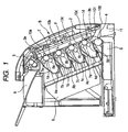
- Fig. 1 is a vertical cross-sectional view of an electrophotographic image forming apparatus serving as a four-color full-color printer and constituting an example of the image forming apparatus embodying the present invention.
- the image forming apparatus is provided, respectively for black, cyan, magenta and yellow colors, with a plural of image forming devices (process cartridges) Aa, Ab, Ac and Ad.
- Each process cartridge integrally includes a drum-shaped electrophotographic photosensitive member (photosensitive drum) 1a, 1b, 1c or 1d constituting an image bearing member, and at least an image forming member acting on the photosensitive drum.
- the process cartridges Aa - Ad each individually is detachably mountable on a main body of the image forming apparatus.
- the process cartridges Aa - Ad are respectively provided, in addition to the photosensitive drums, with charging rollers 7a, 7b, 7c, 7d and developing rollers 8a, 8b, 8c, 8d as image forming members.
- surfaces of the photosensitive drums 1a -1d are uniformly charged, in a charging step, by the charging rollers 7a - 7d, and, in an exposure step or a latent image forming step, are exposed to light in an area where an image is to be formed, by an exposure apparatus 6 such as a laser, thereby forming electrostatic latent images on the photosensitive drums 1a - 1d.
- an exposure apparatus 6 such as a laser
- the electrostatic latent images on the photosensitive drums 1a - 1d are developed by deposition of developers (toners) of respective colors by the developing rollers 8a - 8d, whereby developer images of the respective colors are formed on the photosensitive drums 1a - 1d.
- a recording material (transfer material) S such as paper, containing in a sheet cassette 1 constituting an recording material containing device is fed, by feed device such as a sheet feeding roller 4, onto a conveyor belt 2 constituting a conveying member.
- the conveyor belt 2 is opposed to the process cartridges Aa - Ad, more specifically to the photosensitive drums 1a - 1d, and is driven by a driving roller 3a whereby the recording material supported on the conveyor belt 2 is conveyed to such photosensitive drums 1a - 1d.
- the conveyor belt 2 is supported under a tension between a driving roller 3a and an idler roller 3b, and, along a belt surface T thus formed, the process cartridges Aa - Ad are arranged in an array with the photosensitive drums 1a - 1d positioned at the side of the belt T.
- Opposed areas of the photosensitive drums 1a - 1d and the belt surface T constitute transfer portions, and transfer rollers 10a, 10b, 10c, 10d constituting transfer members are positioned in such transport portions and at a side opposite to the side of the belt surface T opposed to the photosensitive drums 1a - 1d.
- the toner images formed in the process cartridges Aa - Ad are transferred, in a transfer step, from the photosensitive drums 1a - 1d onto the recording material under a bias voltage application to the transfer rollers 10a - 10d, and, the recording material bearing the unfixed toner image is subjected, in a fixing step, to fixation of the image by heat and pressure in a fixing device 5, then discharged to a sheet discharge portion 9 and stacked.
- a door B constituting an opening and closing device which can be opened from or closed to the main body of the apparatus, is opened and closed for replacing the process cartridges or for a jam process.
- the door B is provided on a front surface (a side surface spreading in the substantially vertical direction) of the main body of the apparatus, and is opened and closed by a rotary motion about a support member 100 as a shaft provided along an axis in a substantially horizontal direction in a lower part.
- the door B is opened or closed at least involving a displacement in the vertical direction, is thus rendered displaceable about the shaft 100 provided in the substantially horizontal direction, and is opened from above to below.
- the conveyor belt 2, the rollers 3a, 3b and the transfer rollers 10a - 10d are constructed as a unit of transfer-conveying device F, which is rendered capable of a rotary motion about a support member (shaft) 101 and is connected in an upper part with a link to the door B, whereby the transfer-conveying device F can be simultaneously opened by opening the door B. Stated differently, the transfer-conveying device F is supported by the door B. In the open state, the belt surface T of the conveyor belt 2 is positioned upward.
- the process cartridges Aa - Ad and the sheet cassette 11 are constructed as consumable-containing units which are rendered mountable on and detachable from the main body of the apparatus.
- the sheet cassette 11 is mounted and detached for example for replenishing or replacing the paper sheets.
- Access positions to the door B and to the process cartridges Aa - Ad and the sheet cassette 11 are all provided in the front side of the apparatus, and the access to such door B and to such process cartridges Aa - Ad and sheet cassette 11 can be made from a same direction.
- Fig. 2 shows an attach/detach operation(an attaching or detaching operation) for example for replacing the process cartridges Aa - Ad and an attach/detach operation(an attaching or detaching operation) for the sheet cassette 11 for example for sheet replenishment.
- the process cartridges Aa - Ad are extracted in an obliquely upward direction (direction H), while the sheet cassette 11 is extracted in a substantially horizontal direction (direction J).
- a surface of the main body of the image forming apparatus for mounting or detaching the process cartridges Aa - Ad and a surface of the main body of the image forming apparatus for mounting or detaching the sheet cassette 11 are positioned in a same side, whereby the attach/detach operation for the process cartridges Aa - Ad and the attach/detach operation for the sheet cassette 11 are executed at a same side of the main body of the image forming apparatus.
- an attach/detach direction(an attaching or detaching direction) for the process cartridges Aa - Ad is different from an attach/detach direction(an attaching or detaching direction) for the sheet cassette 11.
- the belt surface T is provided along a vertically inclined direction, namely in a direction inclined from a vertical direction.
- the belt surface T is inclined along a direction in which the belt surface T is shifted, from below to above, toward the process cartridges. Therefore, the process cartridges Aa - Ad are arranged obliquely, with the photosensitive drums 1a - 1d directed upwards.
- the plural process cartridges Aa - Ad are inclined from the vertical direction, and an upper positioned cartridge (for example Ac) among the plural process cartridges Aa - Ad is more distant from the side of the door B than a lower positioned cartridge (for example Ad).
- the upper positioned cartridge (for example Ac) is positioned, with respect to the lower positioned cartridge (for example Ad), opposite to the door B.
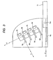
- FIG. 3 schematically shows a guide used in attaching or detaching the process cartridges and the sheet cassette 11.
- Cartridge guide members Ga, Gb, Gc and Gd are provided for respectively guiding the process cartridges Aa - Ad, which can be attached to or detached from the main body of the apparatus by moving the process cartridges Aa - Ad along a direction H.
- an engaging protrusion 11a provided on the sheet cassette 11 and a cassette guide member 11b which engages with the engaging protrusion 11a thereby guiding the displacement of the sheet cassette 11, which can be attached to or detached from the main body of the apparatus by moving the sheet cassette 11 along a direction J.
- the attach/detach operation of the sheet cassette 11 is executed in a lower part of the door B, with a substantially horizontal attach/detach direction J.
- the attach/detach direction H for the process cartridges Aa - Ad is different from the attach/detach direction J for the sheet cassette 11.
- a direction K of array of the process cartridges Aa - Ad is substantially perpendicular, in the present embodiment, to the attach/detach direction of the process cartridges Aa - Ad.
- the attach/detach direction of the process cartridges Aa - Ad is rendered oblique to the attach/detach direction of the sheet cassette 11, thereby securing an area C (called attach/detach trajectory(attaching or detaching trajectory) of process cartridges) as shown in Fig. 2 , defined by trajectories of the process cartridges Aa - Ad at the attach/detach operation thereof.
- an area C as an area in which the process cartridges Aa - Ad are rendered movable, parallel to an extension of the attach/detach direction of the process cartridges Aa - Ad, extending in an obliquely upward direction from the door B and the sheet cassette 11.
- an area D (called attach/detach trajectory(attaching or detaching trajectory) of cassette 11) constituting a lower and horizontal trajectory for the attach/detach operation of the sheet cassette 11.
- the area D is secured as an area in which the sheet cassette 11 is rendered movable, parallel to an extension of the attach/detach direction of the sheet cassette 11.
- the door B is positioned and fixed in a position in an area E defined between the areas C and D.
- process cartridges Aa - Ad are inclined not only in the attach/detach direction thereof but also in the direction of arrangement thereof, even a lower process cartridge can be attached or detached without interfering with the upper process cartridges, whereby the process cartridge is not restricted in shape.
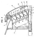
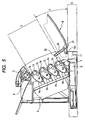
- Figs. 4 and 5 illustrate positioning device for positioning the door B when it is opened.
- Such rotary shaft 21, engaging protrusion 23 and engaging member 22 constitute the positioning device at the opened state of the door B.
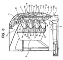
- the image forming apparatus shown in Fig. 6 has constituting components same as those in the embodiment of the invention shown in Fig. 1 , but a sheet conveying path constituted of photosensitive drums 1a - 1d and a conveyor belt 24 in cartridges La, Lb, Lc and Ld are not inclined obliquely but is provided in the vertical direction.
- the uppermost cartridge La cannot be attached or detached in an inclined direction because of the presence of a fixing device 5 above.
- the attach/detach direction of the cartridges La - Ld has to be selected in a horizontal direction N. If the opening angle of a door M is defined, in a similar manner as in Fig. 2 , so as to enable the attach/detach operation of a sheet cassette 11 in the horizontal direction J, the lowermost cartridge Ld comes into contact with the door M and cannot therefore be attached or detached.
- the door M has to be rotated by at least 90° until the belt 24 becomes horizontal, and then the sheet cassette 11 cannot be attached or detached.
- the attach/detach direction of the process cartridge Aa - Ad is inclined with respect to the attach/detach direction of the sheet cassette 11, to form an attach/detach trajectory in the area C shown in Fig. 2 , while a space is defined as the area E between the area C and the area D constituting an attach/detach trajectory of the sheet cassette 11, and the door B in an open state is provided in such space. It is thus rendered possible to attach/detach the process cartridges Aa - Ad and the sheet cassette 11 at the same time thereby improving the operability.
- the operability can be further improved as the open/close operation of the door, the attach/detach operation of the process cartridges and the attach/detach operation of the sheet cassette can all be executed in a same direction with respect to the main body of the apparatus.
- the apparatus can be made further compact by providing the sheet conveying path in an inclined position.
- the process cartridges and the sheet cassette can be attached or detached at the same time in the embodiment implies that both the process cartridges and the sheet cassette can be accessed without further moving the door in the open state.
- the sheet cassette is attached or detached in the horizontal direction, but such configuration is not restrictive.
- the present embodiment is constructed as a full-color printer utilizing four process cartridges, but a monochromatic printer utilizing one process cartridge only can also be constructed, and a similar effect can also be obtained by constructing the conveyor belt with a conveying roller or the like.
- the conveying member moving in opposition to the photosensitive drum is constituted of a conveyor belt for conveying a recording material, but it may also be constituted of an intermediate transfer member (intermediate transfer belt) for bearing and carrying a toner image.
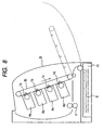
- the present invention is applicable also to an image forming apparatus of an intermediate transfer type as shown in Fig. 8 , in which a toner image is transferred from an image bearing member 1 onto an intermediate transfer member 30 whereby plural toner images are once borne on the intermediate transfer member and then collectively transferred onto a recording material S.
- a dimension, a material, a shape, a relative position and the like are not to be construed to limit the invention to such description, unless a particularly specifying description is provided.
Description
- The present invention relates to an image forming apparatus utilizing an electrophotographic process or an electrostatic recording process such as a copying apparatus, a printer or a facsimile apparatus, and more particularly an image forming apparatus provided with an opening and closing device which is opened from or closed to a main body of the apparatus.
- A prior image forming apparatus particularly utilizing an electrophotographic process is often provided with a process cartridge integrally including a photosensitive member serving as an image bearing member and image forming device such as a developing apparatus for interaction therewith, or a unit containing consumables to be replaced or replenished by a user, such as a transfer material container (sheet cassette) containing a transfer material such as paper sheet for image formation. Also various proposals have been made for improving the operability at the replacement of the process cartridge or at a paper replenishment to the sheet cassette.
- For example,
JP-A-08-115042 - Such a conventional structure, however, is a laterally opening type in which a front cover is opened about a vertical axis (hinge) and the front cover is merely supported at the hinge side, so that it is difficult to maintain a same positional precision of the front cover, to the main body of the apparatus, at left and at right (hinged side and opposite side).
- Particularly in case image forming device is mounted on the front cover, the positional precision becomes different at the left and the right of the image forming apparatus, thus hindering a satisfactory image formation.
- Thus,
JP-A-06-110262 - It is described that, in such apparatus, a sheet cassette can be mounted and detached from the front side of the apparatus, but device which determines an open position of the front cover is not described, and the replacement of the process unit is made possible but the replacement of the sheet cassette may be hindered depending upon the open position of the front cover.
- Also
JP-A-08-022 157 JP-A-2001-356550 - In a full-color image forming apparatus, there are provided with a plurality of process cartridges each having a photosensitive member for respective colors, and an improvement in the maintenance property because of an increased frequency of replacements. Also the presence of plural process cartridges tends to increase the dimension of the apparatus, and there is desired an apparatus capable of suppressing an increase in the dimension thereof even with an improved maintenance property.
- The
US-A-5 444515 discloses a color image forming apparatus with a rotatable door and developing units which can be detachably mounted in the main body when the door is open. - The
EP-A-1 331 525 shows a similar color image forming apparatus, wherein the direction of the detachment of the image forming devices is inclined upwards. Furthermore, the image forming apparatus comprises a sheet container positioned below the plurality of image forming devices. - The
EP-A-1 387 226 and theEP-A-0 346 934 disclose further image forming apparatuses. - It is the object of the invention to provide an image forming apparatus capable of improving operability of detachable image forming device without increasing the dimension of the apparatus.
- This object is achieved by an image forming apparatus having the features of claim 1. Advantageous further formations are subject of the dependent claims.
- Still other objects of the present invention will become fully apparent from the following detailed description.
-
-
Fig. 1 is a view showing an image forming apparatus embodying the present invention; -
Fig. 2 is a view showing an open door state; -
Fig. 3 is a view showing an attaching/detaching guide for a cartridge and a cassette; -
Fig. 4 is a view showing door positioning device in a closed door state; -
Fig. 5 is a view showing a state where the door in an open state is positioned; -
Fig. 6 is view showing an image forming apparatus of a comparative example; -
Fig. 7 is a view showing door positioning device in an open door state; and -
Fig. 8 is a view showing another image forming apparatus to which the invention is applicable. - In the following, an embodiment of the present invention will be explained with reference to the accompanying drawings.
-
Fig. 1 is a vertical cross-sectional view of an electrophotographic image forming apparatus serving as a four-color full-color printer and constituting an example of the image forming apparatus embodying the present invention. - Now an image forming operation of this image forming apparatus will be explained with reference to
Fig. 1 . - The image forming apparatus is provided, respectively for black, cyan, magenta and yellow colors, with a plural of image forming devices (process cartridges) Aa, Ab, Ac and Ad. Each process cartridge integrally includes a drum-shaped electrophotographic photosensitive member (photosensitive drum) 1a, 1b, 1c or 1d constituting an image bearing member, and at least an image forming member acting on the photosensitive drum. The process cartridges Aa - Ad each individually is detachably mountable on a main body of the image forming apparatus.
- The process cartridges Aa - Ad are respectively provided, in addition to the photosensitive drums, with
charging rollers rollers - In the process cartridges Aa - Ad, surfaces of the
photosensitive drums 1a -1d are uniformly charged, in a charging step, by thecharging rollers 7a - 7d, and, in an exposure step or a latent image forming step, are exposed to light in an area where an image is to be formed, by anexposure apparatus 6 such as a laser, thereby forming electrostatic latent images on thephotosensitive drums 1a - 1d. Then the electrostatic latent images on thephotosensitive drums 1a - 1d are developed by deposition of developers (toners) of respective colors by the developingrollers 8a - 8d, whereby developer images of the respective colors are formed on thephotosensitive drums 1a - 1d. - On the other hand, in synchronization with the image formation on the process cartridges Aa - Ad, a recording material (transfer material) S such as paper, containing in a sheet cassette 1 constituting an recording material containing device is fed, by feed device such as a
sheet feeding roller 4, onto a conveyor belt 2 constituting a conveying member. The conveyor belt 2 is opposed to the process cartridges Aa - Ad, more specifically to thephotosensitive drums 1a - 1d, and is driven by adriving roller 3a whereby the recording material supported on the conveyor belt 2 is conveyed to suchphotosensitive drums 1a - 1d. - The conveyor belt 2 is supported under a tension between a
driving roller 3a and anidler roller 3b, and, along a belt surface T thus formed, the process cartridges Aa - Ad are arranged in an array with thephotosensitive drums 1a - 1d positioned at the side of the belt T. - Opposed areas of the
photosensitive drums 1a - 1d and the belt surface T constitute transfer portions, andtransfer rollers photosensitive drums 1a - 1d. - The toner images formed in the process cartridges Aa - Ad are transferred, in a transfer step, from the
photosensitive drums 1a - 1d onto the recording material under a bias voltage application to thetransfer rollers 10a - 10d, and, the recording material bearing the unfixed toner image is subjected, in a fixing step, to fixation of the image by heat and pressure in afixing device 5, then discharged to asheet discharge portion 9 and stacked. - Then, with reference to
Figs. 1 and2 , there will be explained an attaching/detaching operation for the process cartridges Aa - Ad of the present embodiment. A door B, constituting an opening and closing device which can be opened from or closed to the main body of the apparatus, is opened and closed for replacing the process cartridges or for a jam process. In the present embodiment, the door B is provided on a front surface (a side surface spreading in the substantially vertical direction) of the main body of the apparatus, and is opened and closed by a rotary motion about asupport member 100 as a shaft provided along an axis in a substantially horizontal direction in a lower part. Thus, the door B is opened or closed at least involving a displacement in the vertical direction, is thus rendered displaceable about theshaft 100 provided in the substantially horizontal direction, and is opened from above to below. - Also the conveyor belt 2, the
rollers transfer rollers 10a - 10d are constructed as a unit of transfer-conveying device F, which is rendered capable of a rotary motion about a support member (shaft) 101 and is connected in an upper part with a link to the door B, whereby the transfer-conveying device F can be simultaneously opened by opening the door B. Stated differently, the transfer-conveying device F is supported by the door B. In the open state, the belt surface T of the conveyor belt 2 is positioned upward. - In the aforementioned image forming apparatus, the process cartridges Aa - Ad and the
sheet cassette 11 are constructed as consumable-containing units which are rendered mountable on and detachable from the main body of the apparatus. Thesheet cassette 11 is mounted and detached for example for replenishing or replacing the paper sheets. Access positions to the door B and to the process cartridges Aa - Ad and thesheet cassette 11 are all provided in the front side of the apparatus, and the access to such door B and to such process cartridges Aa - Ad andsheet cassette 11 can be made from a same direction. -
Fig. 2 shows an attach/detach operation(an attaching or detaching operation) for example for replacing the process cartridges Aa - Ad and an attach/detach operation(an attaching or detaching operation) for thesheet cassette 11 for example for sheet replenishment. By opening the door B supporting the conveyor belt 2, thedriving roller 3a and theidler roller 3b, the process cartridges Aa - Ad can be accessed and can be detached or mounted. - As shown in
Fig. 2 , the process cartridges Aa - Ad are extracted in an obliquely upward direction (direction H), while thesheet cassette 11 is extracted in a substantially horizontal direction (direction J). Thus, a surface of the main body of the image forming apparatus for mounting or detaching the process cartridges Aa - Ad and a surface of the main body of the image forming apparatus for mounting or detaching thesheet cassette 11 are positioned in a same side, whereby the attach/detach operation for the process cartridges Aa - Ad and the attach/detach operation for thesheet cassette 11 are executed at a same side of the main body of the image forming apparatus. - However, an attach/detach direction(an attaching or detaching direction) for the process cartridges Aa - Ad is different from an attach/detach direction(an attaching or detaching direction) for the
sheet cassette 11. - In the present embodiment, as shown in
Fig. 1 , the belt surface T is provided along a vertically inclined direction, namely in a direction inclined from a vertical direction. The belt surface T is inclined along a direction in which the belt surface T is shifted, from below to above, toward the process cartridges. Therefore, the process cartridges Aa - Ad are arranged obliquely, with thephotosensitive drums 1a - 1d directed upwards. Thus the plural process cartridges Aa - Ad are inclined from the vertical direction, and an upper positioned cartridge (for example Ac) among the plural process cartridges Aa - Ad is more distant from the side of the door B than a lower positioned cartridge (for example Ad). In this manner, the upper positioned cartridge (for example Ac) is positioned, with respect to the lower positioned cartridge (for example Ad), opposite to the door B. -
Fig. 3 schematically shows a guide used in attaching or detaching the process cartridges and thesheet cassette 11. Cartridge guide members Ga, Gb, Gc and Gd are provided for respectively guiding the process cartridges Aa - Ad, which can be attached to or detached from the main body of the apparatus by moving the process cartridges Aa - Ad along a direction H. There are shown an engagingprotrusion 11a provided on thesheet cassette 11 and acassette guide member 11b which engages with the engagingprotrusion 11a thereby guiding the displacement of thesheet cassette 11, which can be attached to or detached from the main body of the apparatus by moving thesheet cassette 11 along a direction J. The attach/detach operation of thesheet cassette 11 is executed in a lower part of the door B, with a substantially horizontal attach/detach direction J. Thus, the attach/detach direction H for the process cartridges Aa - Ad is different from the attach/detach direction J for thesheet cassette 11. - A direction K of array of the process cartridges Aa - Ad is substantially perpendicular, in the present embodiment, to the attach/detach direction of the process cartridges Aa - Ad.
- Thus, in the present embodiment, the attach/detach direction of the process cartridges Aa - Ad is rendered oblique to the attach/detach direction of the
sheet cassette 11, thereby securing an area C (called attach/detach trajectory(attaching or detaching trajectory) of process cartridges) as shown inFig. 2 , defined by trajectories of the process cartridges Aa - Ad at the attach/detach operation thereof. Thus, there is secured the area C as an area in which the process cartridges Aa - Ad are rendered movable, parallel to an extension of the attach/detach direction of the process cartridges Aa - Ad, extending in an obliquely upward direction from the door B and thesheet cassette 11. Also there is secured an area D (called attach/detach trajectory(attaching or detaching trajectory) of cassette 11) constituting a lower and horizontal trajectory for the attach/detach operation of thesheet cassette 11. Thus, there is secured the area D as an area in which thesheet cassette 11 is rendered movable, parallel to an extension of the attach/detach direction of thesheet cassette 11. Also, in an opened state of the door B, the door B is positioned and fixed in a position in an area E defined between the areas C and D. - In the present embodiment, therefore, it is rendered possible to attach or detach the process cartridges Aa - Ad and the
sheet cassette 11 at the same time while suppressing the entire height of the apparatus, thereby improving the operability. - Also in the present embodiment, as the process cartridges Aa - Ad are inclined not only in the attach/detach direction thereof but also in the direction of arrangement thereof, even a lower process cartridge can be attached or detached without interfering with the upper process cartridges, whereby the process cartridge is not restricted in shape.
-
Figs. 4 and5 illustrate positioning device for positioning the door B when it is opened. - There are shown a rotary shaft (protruding portion) 21 provided on the door B, an engaging
protrusion 22 provided on the main body of the apparatus, and an engagingmember 22 rendered rotatable about therotary shaft 21 and having an elongated hole in which the engaging protrusion can engage. Suchrotary shaft 21, engagingprotrusion 23 and engagingmember 22 constitute the positioning device at the opened state of the door B. - When the door B is opened from a state shown in
Fig. 4 to a state shown inFig. 5 , therotary shaft 21 is displaced with a displacement of the engagingmember 22, and, when an end of the elongated hole of the engagingmember 22 comes into a contact with the engagingprotrusion 23 thereby inhibiting the displacement of the engagingmember 22, the door B is fixed and positioned in such position. - Now an image forming apparatus shown in
Figs. 6 and7 will be explained as a comparative example. The image forming apparatus shown inFig. 6 has constituting components same as those in the embodiment of the invention shown inFig. 1 , but a sheet conveying path constituted ofphotosensitive drums 1a - 1d and aconveyor belt 24 in cartridges La, Lb, Lc and Ld are not inclined obliquely but is provided in the vertical direction. - In this comparative example, the uppermost cartridge La cannot be attached or detached in an inclined direction because of the presence of a
fixing device 5 above. In order to avoid such drawback, the attach/detach direction of the cartridges La - Ld has to be selected in a horizontal direction N. If the opening angle of a door M is defined, in a similar manner as inFig. 2 , so as to enable the attach/detach operation of asheet cassette 11 in the horizontal direction J, the lowermost cartridge Ld comes into contact with the door M and cannot therefore be attached or detached. In order to enable an attach/detach operation of the cartridge Ld, the door M has to be rotated by at least 90° until thebelt 24 becomes horizontal, and then thesheet cassette 11 cannot be attached or detached. - In the comparative example, therefore, it is not possible to execute the attach/detach operation of the cartridges La - Ld and the attach/detach operation of the sheet cassette at the same time in a state where the door M is fixed in a certain open position.
- Also in order to enable the attach/detach operation of the
sheet cassette 11 even when the door M is opened until thebelt 24 becomes horizontal, it is conceivable to increase the gap between thesheet cassette 11 and the cartridge Ld or to increase the gap between the cartridge La and the fixingdevice 5 thereby enabling the attach/detach operation in an oblique direction, but such methods inevitably increase the height of the image forming apparatus, thereby resulting in an undesirably bulky structure thereof. - Thus, in the present embodiment, the attach/detach direction of the process cartridge Aa - Ad is inclined with respect to the attach/detach direction of the
sheet cassette 11, to form an attach/detach trajectory in the area C shown inFig. 2 , while a space is defined as the area E between the area C and the area D constituting an attach/detach trajectory of thesheet cassette 11, and the door B in an open state is provided in such space. It is thus rendered possible to attach/detach the process cartridges Aa - Ad and thesheet cassette 11 at the same time thereby improving the operability. The operability can be further improved as the open/close operation of the door, the attach/detach operation of the process cartridges and the attach/detach operation of the sheet cassette can all be executed in a same direction with respect to the main body of the apparatus. - Furthermore, the apparatus can be made further compact by providing the sheet conveying path in an inclined position.
- In the present embodiment, "the process cartridges and the sheet cassette can be attached or detached at the same time" in the embodiment implies that both the process cartridges and the sheet cassette can be accessed without further moving the door in the open state.
- In the present embodiment, the sheet cassette is attached or detached in the horizontal direction, but such configuration is not restrictive.
- Also the present embodiment is constructed as a full-color printer utilizing four process cartridges, but a monochromatic printer utilizing one process cartridge only can also be constructed, and a similar effect can also be obtained by constructing the conveyor belt with a conveying roller or the like.
- Also in the present embodiment, the conveying member moving in opposition to the photosensitive drum is constituted of a conveyor belt for conveying a recording material, but it may also be constituted of an intermediate transfer member (intermediate transfer belt) for bearing and carrying a toner image. Thus the present invention is applicable also to an image forming apparatus of an intermediate transfer type as shown in
Fig. 8 , in which a toner image is transferred from an image bearing member 1 onto anintermediate transfer member 30 whereby plural toner images are once borne on the intermediate transfer member and then collectively transferred onto a recording material S. - As to the components of the aforementioned image forming apparatus, a dimension, a material, a shape, a relative position and the like are not to be construed to limit the invention to such description, unless a particularly specifying description is provided.
- The present invention has been explained by an embodiment, but the invention is not at all limited to such embodiment and is subject to any and all modifications within the scope of the invention as defined by the following claims.
Claims (9)
- An image forming apparatus comprising:an opening and closing device (B) that is capable of being opened or closed with respect to a main body of the image forming apparatus;a support member (100) which pivotably supports said opening and closing device (B);a plurality of image forming devices (Aa, Ab, Ac, Ad) which is capable of being detachably mounted on the main body in a state where said opening and closing device (B) is opened;a recording material containing device (1) which contains a recording material and which is capable of being detachably mounted on the main body,wherein said plurality of image forming devices (Aa, Ab, Ac, Ad) are provided above said recording material containing devices (1),wherein the image forming apparatus is configured such that both attaching or detaching said recording material containing device (1) and attaching or detaching said plurality of image forming devices (Aa, Ab, Ac, Ad) are performed at the same side of the main body, a detaching direction of said plurality of image forming devices (Aa, Ab, Ac, Ad) is inclined upwards, while a detaching direction of said recording material containing device (1) is substantially horizontal,a positioning device (22, 23) for positioning said opening and closing device (B) by limiting the movement of said opening and closing device (B) when said opening and closing device (B) is opened around said support member (100);wherein said positioning device (22, 23) positions said opening and closing device (B) in a space defined between an attaching or detaching trajectory of said plurality of image forming devices (Aa, Ab, Ac, Ad) and an attaching or detaching trajectory of said recording material containing device (1).
- An image forming apparatus according to claim 1, wherein said support member (100) is a shaft, said opening and closing device (B) is movable about said shaft provided in a substantially horizontal direction.
- An image forming apparatus according to claim 2, wherein said opening and closing device (B) is opened from above to below.
- An image forming apparatus according to claim 1, wherein each of said plurality of image forming devices (Aa, Ab, Ac, Ad) is a cartridge integrally including a photosensitive member (1a, 1b, 1c, 1d) and at least an image forming member (8a, 8b, 8c, 8d) acting on said photosensitive member (1a, 1b, 1c, 1d), and a plurality of said cartridges correspond respectively to different colors.
- An image forming apparatus according to claim 1, further comprising a transfer-conveying device (F) opposed to said plurality of image forming devices (Aa, Ab, Ac, Ad) and supported by said opening and closing device (B), wherein said transfer-conveying device (F) is capable of being opened in linkage with an opening operation of said opening and closing device (B) and positioned at said space.
- An image forming apparatus according to claim 5, wherein said transfer-conveying device (F) comprises a belt (2).
- An image forming apparatus according to claim 1, wherein all of said image forming devices (Aa, Ab, Ac, Ad) are positioned in a line inclined backwards with respect the vertical direction, such that an upper positioned cartridge among the plural process cartridges is more distant from the side of said opening and closing device (B) than a lower positioned cartridge.
- An image forming apparatus according to claim 7, wherein the direction of arrangement of said plurality of image forming devices (Aa, Ab, Ac, Ad) is substantially perpendicular to an attaching or detaching direction of said plurality of image forming devices (Aa, Ab, Ac, Ad).
- An image forming apparatus according to claim 1, wherein one of said plurality of image forming devices (Aa, Ab, Ac, Ad) is provided above another of said plurality of image forming devices (Aa, Ab, Ac, Ad).
Applications Claiming Priority (4)
| Application Number | Priority Date | Filing Date | Title |
|---|---|---|---|
| JP2004054332 | 2004-02-27 | ||
| JP2004054332 | 2004-02-27 | ||
| JP2005026529 | 2005-02-02 | ||
| JP2005026529A JP4717455B2 (en) | 2004-02-27 | 2005-02-02 | Image forming apparatus |
Publications (2)
| Publication Number | Publication Date |
|---|---|
| EP1569050A1 EP1569050A1 (en) | 2005-08-31 |
| EP1569050B1 true EP1569050B1 (en) | 2014-06-18 |
Family
ID=34752176
Family Applications (1)
| Application Number | Title | Priority Date | Filing Date |
|---|---|---|---|
| EP05004083.1A Expired - Fee Related EP1569050B1 (en) | 2004-02-27 | 2005-02-24 | Color image forming apparatus with door comprising a sheet transport belt |
Country Status (5)
| Country | Link |
|---|---|
| US (1) | US7130560B2 (en) |
| EP (1) | EP1569050B1 (en) |
| JP (1) | JP4717455B2 (en) |
| KR (1) | KR20060042194A (en) |
| CN (1) | CN100390682C (en) |
Families Citing this family (23)
| Publication number | Priority date | Publication date | Assignee | Title |
|---|---|---|---|---|
| JP3870919B2 (en) * | 2003-03-20 | 2007-01-24 | ブラザー工業株式会社 | Image forming apparatus |
| JP2006036432A (en) * | 2004-07-26 | 2006-02-09 | Oki Data Corp | Image forming device |
| JP4630688B2 (en) * | 2004-08-30 | 2011-02-09 | キヤノン株式会社 | Development device |
| JP4658650B2 (en) * | 2005-03-17 | 2011-03-23 | ブラザー工業株式会社 | Image forming apparatus |
| JP4417281B2 (en) * | 2005-03-18 | 2010-02-17 | ブラザー工業株式会社 | Image forming apparatus |
| JP4850427B2 (en) * | 2005-03-28 | 2012-01-11 | キヤノン株式会社 | Process cartridge and electrophotographic image forming apparatus |
| JP2007163741A (en) * | 2005-12-13 | 2007-06-28 | Fuji Xerox Co Ltd | Image forming apparatus |
| JP4378374B2 (en) | 2006-03-10 | 2009-12-02 | キヤノン株式会社 | Process cartridge, developer supply cartridge, and electrophotographic image forming apparatus |
| JP4883353B2 (en) * | 2006-09-08 | 2012-02-22 | 富士ゼロックス株式会社 | Image forming apparatus |
| KR101346164B1 (en) * | 2007-01-26 | 2013-12-31 | 삼성전자주식회사 | Locking apparatus and image forming apparatus |
| KR101273593B1 (en) * | 2007-02-01 | 2013-06-11 | 삼성전자주식회사 | Image forming apparatus and method of feeding printing medium |
| JP5034609B2 (en) * | 2007-03-30 | 2012-09-26 | 富士ゼロックス株式会社 | Image forming apparatus |
| JP5159176B2 (en) * | 2007-06-15 | 2013-03-06 | キヤノン株式会社 | Image forming apparatus |
| JP5159225B2 (en) * | 2007-09-21 | 2013-03-06 | キヤノン株式会社 | Image forming apparatus |
| US20090083128A1 (en) * | 2007-09-24 | 2009-03-26 | Introspective Solutions, Llc | Predicted variable analysis based on evaluation variables relating to site selection |
| JP5127565B2 (en) * | 2008-05-23 | 2013-01-23 | キヤノン株式会社 | Cartridge and image forming apparatus |
| JP5004870B2 (en) * | 2008-05-23 | 2012-08-22 | キヤノン株式会社 | Process cartridge and electrophotographic image forming apparatus |
| JP4592113B2 (en) * | 2009-03-02 | 2010-12-01 | キヤノン株式会社 | Color electrophotographic image forming apparatus |
| JP5762054B2 (en) * | 2010-03-16 | 2015-08-12 | キヤノン株式会社 | Process cartridge and image forming apparatus |
| JP5839826B2 (en) | 2011-04-22 | 2016-01-06 | キヤノン株式会社 | Development device reproduction method, process cartridge reproduction method, development device, and process cartridge |
| JP5460824B2 (en) | 2011-12-09 | 2014-04-02 | キヤノン株式会社 | cartridge |
| CN116165857A (en) | 2017-12-13 | 2023-05-26 | 佳能株式会社 | Cartridge and image forming apparatus |
| CN116339094A (en) | 2020-12-07 | 2023-06-27 | 佳能株式会社 | Toner container and image forming system |
Family Cites Families (51)
| Publication number | Priority date | Publication date | Assignee | Title |
|---|---|---|---|---|
| US142994A (en) * | 1873-09-23 | Improvement in sash-holders | ||
| US5169A (en) * | 1847-06-19 | Straw-cutter | ||
| US185984A (en) * | 1877-01-02 | Improvement in heating box-irons | ||
| US156856A (en) * | 1874-11-17 | Improvement in saw-filing benches | ||
| US156848A (en) * | 1874-11-17 | Improvement in machines for burnishing boot and shoe heels | ||
| US649188A (en) * | 1899-03-31 | 1900-05-08 | Henry Herman Westinghouse | Draw-gear and buffing apparatus. |
| DE68920781T2 (en) | 1988-06-17 | 1995-06-14 | Canon Kk | Image recorder. |
| GB2238758B (en) * | 1989-12-06 | 1994-01-12 | Ricoh Kk | Image recording apparatus constituting of selectable units |
| JPH0484166A (en) * | 1990-07-26 | 1992-03-17 | Konica Corp | Image forming device |
| JPH06110262A (en) | 1992-09-28 | 1994-04-22 | Fujitsu Ltd | Image forming device |
| JPH06250450A (en) | 1993-02-23 | 1994-09-09 | Konica Corp | Color image forming device |
| JP3273271B2 (en) | 1993-03-18 | 2002-04-08 | コニカ株式会社 | Color image forming equipment |
| US5444515A (en) | 1993-02-23 | 1995-08-22 | Konica Corporation | Color image forming apparatus with mountable cartridge therein |
| JPH0822157A (en) | 1994-07-07 | 1996-01-23 | Ricoh Co Ltd | Electrophotographic device |
| JPH08115042A (en) | 1994-10-18 | 1996-05-07 | Canon Inc | Image forming device |
| JPH08254862A (en) | 1995-03-15 | 1996-10-01 | Fujitsu Ltd | Image forming device |
| JP2875203B2 (en) * | 1995-03-27 | 1999-03-31 | キヤノン株式会社 | Electrophotographic image forming apparatus, process cartridge, driving force transmitting component, and electrophotographic photosensitive drum |
| US5887228A (en) * | 1995-10-16 | 1999-03-23 | Ricoh Company, Ltd. | Color image forming apparatus including process cartridge |
| US6226478B1 (en) * | 1996-03-21 | 2001-05-01 | Canon Kabushiki Kaisha | Process cartridge having drive mount for photosensitive drum |
| US6240266B1 (en) * | 1996-03-21 | 2001-05-29 | Canon Kabushiki Kaisha | Process cartridge and drum mount for photosensitive drum |
| JP3809250B2 (en) * | 1996-07-04 | 2006-08-16 | キヤノン株式会社 | Support component, developer container, process cartridge, and electrophotographic image forming apparatus |
| JPH1069199A (en) * | 1996-08-29 | 1998-03-10 | Canon Inc | Cleaner, process cartridge, electrophotographic image forming device, and cleaning frame |
| CA2216905C (en) * | 1996-09-26 | 2001-03-06 | Canon Kabushiki Kaisha | Process cartridge, electrophotographic image forming apparatus driving force transmission part and electrophotographic photosensitive drum |
| JP3745047B2 (en) * | 1996-09-26 | 2006-02-15 | キヤノン株式会社 | Electrophotographic image forming apparatus and process cartridge |
| JP3745049B2 (en) * | 1996-09-26 | 2006-02-15 | キヤノン株式会社 | Process cartridge and electrophotographic image forming apparatus |
| JP3658202B2 (en) * | 1998-08-31 | 2005-06-08 | キヤノン株式会社 | Developing cartridge assembly method |
| JP3338023B2 (en) * | 1999-09-27 | 2002-10-28 | キヤノン株式会社 | Process cartridge, handle mounting method, and electrophotographic image forming apparatus |
| JP3338024B2 (en) * | 1999-09-27 | 2002-10-28 | キヤノン株式会社 | Handle, process cartridge, handle mounting method, and electrophotographic image forming apparatus |
| JP2001249601A (en) * | 2000-03-03 | 2001-09-14 | Canon Inc | Image forming device |
| JP2001281996A (en) * | 2000-04-03 | 2001-10-10 | Canon Inc | Developing cartridge, processing cartridge and electrophotographic image forming device |
| JP2001356550A (en) | 2000-06-16 | 2001-12-26 | Brother Ind Ltd | Color image forming device |
| JP2001356548A (en) * | 2000-06-14 | 2001-12-26 | Brother Ind Ltd | Color image forming device |
| US6798430B2 (en) * | 2000-06-14 | 2004-09-28 | Brother Kogyo Kabushiki Kaisha | Tandem type color image forming device having a plurality of process cartridges arrayed in running direction of intermediate image transfer member |
| JP2002006609A (en) * | 2000-06-26 | 2002-01-11 | Canon Inc | Toner sealing member, developing cartridge, process cartridge and electrophotographic image forming device |
| JP2002023476A (en) * | 2000-07-07 | 2002-01-23 | Canon Inc | Developing cartridge, process cartridge and electrophotographic image forming device |
| JP2002193497A (en) * | 2000-10-20 | 2002-07-10 | Ricoh Co Ltd | Paper feeder and image forming device provided with this paper feeder |
| JP3652246B2 (en) * | 2000-12-21 | 2005-05-25 | キヤノン株式会社 | Process cartridge and image forming apparatus |
| JP2003167412A (en) * | 2001-12-03 | 2003-06-13 | Seiko Epson Corp | Image forming apparatus |
| JP4125007B2 (en) | 2002-01-11 | 2008-07-23 | キヤノン株式会社 | Process cartridge and electrophotographic image forming apparatus |
| EP1331525A3 (en) | 2002-01-25 | 2004-06-23 | Ricoh Company, Ltd. | Image forming apparatus with improved image quality and maintenance workability |
| JP3586675B2 (en) | 2002-02-08 | 2004-11-10 | 株式会社リコー | Image forming device |
| JP3595798B2 (en) * | 2002-01-31 | 2004-12-02 | キヤノン株式会社 | Process cartridge and electrophotographic image forming apparatus |
| JP3634807B2 (en) | 2002-02-20 | 2005-03-30 | キヤノン株式会社 | Process cartridge and image forming apparatus |
| JP2003241616A (en) * | 2002-02-21 | 2003-08-29 | Canon Inc | Image forming device |
| JP3658372B2 (en) * | 2002-02-22 | 2005-06-08 | キヤノン株式会社 | Process cartridge and separation holding member for process cartridge |
| JP2003276276A (en) * | 2002-03-27 | 2003-09-30 | Brother Ind Ltd | Imaging apparatus |
| JP4174380B2 (en) | 2002-07-04 | 2008-10-29 | キヤノン株式会社 | Electrophotographic photosensitive drum and process cartridge |
| CN2682454Y (en) | 2002-07-26 | 2005-03-02 | 精工爱普生株式会社 | Image forming device comprising transfer printing band |
| JP3577308B2 (en) * | 2003-04-21 | 2004-10-13 | 株式会社リコー | Image forming apparatus |
| KR100547128B1 (en) * | 2003-07-04 | 2006-01-26 | 삼성전자주식회사 | Electrophotographic printer |
| JP3673793B2 (en) * | 2003-08-29 | 2005-07-20 | キヤノン株式会社 | Process cartridge, process cartridge mounting mechanism, and electrophotographic image forming apparatus |
-
2005
- 2005-02-02 JP JP2005026529A patent/JP4717455B2/en not_active Expired - Fee Related
- 2005-02-24 EP EP05004083.1A patent/EP1569050B1/en not_active Expired - Fee Related
- 2005-02-24 US US11/063,642 patent/US7130560B2/en active Active
- 2005-02-25 KR KR1020050015626A patent/KR20060042194A/en active Search and Examination
- 2005-02-25 CN CNB2005100087400A patent/CN100390682C/en not_active Expired - Fee Related
Also Published As
| Publication number | Publication date |
|---|---|
| EP1569050A1 (en) | 2005-08-31 |
| CN1661499A (en) | 2005-08-31 |
| JP4717455B2 (en) | 2011-07-06 |
| US7130560B2 (en) | 2006-10-31 |
| US20050191086A1 (en) | 2005-09-01 |
| JP2005275374A (en) | 2005-10-06 |
| CN100390682C (en) | 2008-05-28 |
| KR20060042194A (en) | 2006-05-12 |
Similar Documents
| Publication | Publication Date | Title |
|---|---|---|
| EP1569050B1 (en) | Color image forming apparatus with door comprising a sheet transport belt | |
| US10852687B2 (en) | Image forming apparatus | |
| JP5127565B2 (en) | Cartridge and image forming apparatus | |
| US7817936B2 (en) | Color electrophotographic image forming apparatus | |
| US7983597B2 (en) | Color electrophotographic image forming apparatus with gripping portions for cartridges | |
| US20140348540A1 (en) | Electrophotographic image forming apparatus | |
| JP5220084B2 (en) | Electrophotographic image forming apparatus | |
| US7269379B2 (en) | Image forming apparatus | |
| US20140037330A1 (en) | Image forming apparatus having a door path regulating member | |
| US10386781B2 (en) | Image forming apparatus comprising intermediate transfer unit movably supported on main body cover | |
| JP2008310120A (en) | Image forming apparatus | |
| US10025261B2 (en) | Image forming apparatus | |
| JP4582508B2 (en) | Image forming apparatus and process cartridge attaching / detaching method | |
| JP6739950B2 (en) | Image forming device | |
| US8639162B2 (en) | Color electrophotographic image forming apparatus | |
| US10222736B2 (en) | Image forming apparatus | |
| JP2018049198A (en) | Image forming apparatus and apparatus body | |
| JP2003122078A (en) | Image forming apparatus | |
| JP4041811B2 (en) | Color image forming apparatus | |
| US20060078350A1 (en) | Color image forming apparatus | |
| JP2006267843A (en) | Image forming apparatus |
Legal Events
| Date | Code | Title | Description |
|---|---|---|---|
| PUAI | Public reference made under article 153(3) epc to a published international application that has entered the european phase |
Free format text: ORIGINAL CODE: 0009012 |
|
| AK | Designated contracting states |
Kind code of ref document: A1 Designated state(s): AT BE BG CH CY CZ DE DK EE ES FI FR GB GR HU IE IS IT LI LT LU MC NL PL PT RO SE SI SK TR |
|
| AX | Request for extension of the european patent |
Extension state: AL BA HR LV MK YU |
|
| 17P | Request for examination filed |
Effective date: 20060228 |
|
| AKX | Designation fees paid |
Designated state(s): DE FR GB |
|
| 17Q | First examination report despatched |
Effective date: 20101008 |
|
| GRAP | Despatch of communication of intention to grant a patent |
Free format text: ORIGINAL CODE: EPIDOSNIGR1 |
|
| GRAJ | Information related to disapproval of communication of intention to grant by the applicant or resumption of examination proceedings by the epo deleted |
Free format text: ORIGINAL CODE: EPIDOSDIGR1 |
|
| GRAP | Despatch of communication of intention to grant a patent |
Free format text: ORIGINAL CODE: EPIDOSNIGR1 |
|
| GRAP | Despatch of communication of intention to grant a patent |
Free format text: ORIGINAL CODE: EPIDOSNIGR1 |
|
| INTG | Intention to grant announced |
Effective date: 20140103 |
|
| GRAS | Grant fee paid |
Free format text: ORIGINAL CODE: EPIDOSNIGR3 |
|
| GRAA | (expected) grant |
Free format text: ORIGINAL CODE: 0009210 |
|
| AK | Designated contracting states |
Kind code of ref document: B1 Designated state(s): DE FR GB |
|
| REG | Reference to a national code |
Ref country code: GB Ref legal event code: FG4D |
|
| REG | Reference to a national code |
Ref country code: DE Ref legal event code: R096 Ref document number: 602005043915 Country of ref document: DE Effective date: 20140731 |
|
| REG | Reference to a national code |
Ref country code: DE Ref legal event code: R097 Ref document number: 602005043915 Country of ref document: DE |
|
| PLBE | No opposition filed within time limit |
Free format text: ORIGINAL CODE: 0009261 |
|
| STAA | Information on the status of an ep patent application or granted ep patent |
Free format text: STATUS: NO OPPOSITION FILED WITHIN TIME LIMIT |
|
| 26N | No opposition filed |
Effective date: 20150319 |
|
| REG | Reference to a national code |
Ref country code: FR Ref legal event code: ST Effective date: 20151030 |
|
| PG25 | Lapsed in a contracting state [announced via postgrant information from national office to epo] |
Ref country code: FR Free format text: LAPSE BECAUSE OF NON-PAYMENT OF DUE FEES Effective date: 20150302 |
|
| PGFP | Annual fee paid to national office [announced via postgrant information from national office to epo] |
Ref country code: GB Payment date: 20180227 Year of fee payment: 14 |
|
| PGFP | Annual fee paid to national office [announced via postgrant information from national office to epo] |
Ref country code: DE Payment date: 20180430 Year of fee payment: 14 |
|
| REG | Reference to a national code |
Ref country code: DE Ref legal event code: R119 Ref document number: 602005043915 Country of ref document: DE |
|
| GBPC | Gb: european patent ceased through non-payment of renewal fee |
Effective date: 20190224 |
|
| PG25 | Lapsed in a contracting state [announced via postgrant information from national office to epo] |
Ref country code: DE Free format text: LAPSE BECAUSE OF NON-PAYMENT OF DUE FEES Effective date: 20190903 Ref country code: GB Free format text: LAPSE BECAUSE OF NON-PAYMENT OF DUE FEES Effective date: 20190224 |