EP1569032A1 - Projection display - Google Patents
Projection display Download PDFInfo
- Publication number
- EP1569032A1 EP1569032A1 EP04735670A EP04735670A EP1569032A1 EP 1569032 A1 EP1569032 A1 EP 1569032A1 EP 04735670 A EP04735670 A EP 04735670A EP 04735670 A EP04735670 A EP 04735670A EP 1569032 A1 EP1569032 A1 EP 1569032A1
- Authority
- EP
- European Patent Office
- Prior art keywords
- diaphragm
- axis
- light
- lens array
- projection display
- Prior art date
- Legal status (The legal status is an assumption and is not a legal conclusion. Google has not performed a legal analysis and makes no representation as to the accuracy of the status listed.)
- Withdrawn
Links
Images


Classifications
-
- H—ELECTRICITY
- H04—ELECTRIC COMMUNICATION TECHNIQUE
- H04N—PICTORIAL COMMUNICATION, e.g. TELEVISION
- H04N9/00—Details of colour television systems
- H04N9/12—Picture reproducers
- H04N9/31—Projection devices for colour picture display, e.g. using electronic spatial light modulators [ESLM]
- H04N9/3141—Constructional details thereof
- H04N9/315—Modulator illumination systems
- H04N9/3152—Modulator illumination systems for shaping the light beam
-
- G—PHYSICS
- G03—PHOTOGRAPHY; CINEMATOGRAPHY; ANALOGOUS TECHNIQUES USING WAVES OTHER THAN OPTICAL WAVES; ELECTROGRAPHY; HOLOGRAPHY
- G03B—APPARATUS OR ARRANGEMENTS FOR TAKING PHOTOGRAPHS OR FOR PROJECTING OR VIEWING THEM; APPARATUS OR ARRANGEMENTS EMPLOYING ANALOGOUS TECHNIQUES USING WAVES OTHER THAN OPTICAL WAVES; ACCESSORIES THEREFOR
- G03B21/00—Projectors or projection-type viewers; Accessories therefor
- G03B21/14—Details
- G03B21/20—Lamp housings
- G03B21/2053—Intensity control of illuminating light
Definitions
- the present invention relates to a projection display apparatus which is capable of controlling projection illuminance.
- a projection display apparatus represented by a liquid crystal projector is more inexpensive and has a larger display size than other systems such as a plasma display panel (PDP), so that a user can enjoy video. Accordingly, this projection display apparatus has come into wide use as a home theater system.
- a method for performing high dynamic ranges by controlling amount of light of a lamp in response to brightness of the image is invented (See for example, Unexamined Japanese Patent Publication No. 2001-100699).
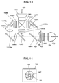
- Fig. 13 is a top view showing an optical layout of a conventional liquid crystal projector.
- Light emitted from lamp 150 of a light source is divided into a plurality of partial luminous fluxes by first lens array 151, and enters into polarization change element 153 via second lens array 152.
- Each partial luminous flux is made its polarization direction arranged, and becomes linear polarization. Then it is transmitted through diaphragm mechanism 165, and enters superimpose lens 154.
- Dichroic mirror 156R reflects only red light, and lets other light pass.
- Dichroic mirror 156G reflects only green light, and lets other light pass.
- red light “R” is reflected and separated at dichroic mirror 156R.
- green light “G” is reflected and separated at dichroic mirror 56G, so that blue light "B” is transmitted.
- Red light is reflected at total reflection mirror 157R, transmitted through field lens 159R and reaches liquid crystal panel 155R.
- Green light "G” is transmitted through field lens 159G and reaches liquid crystal panel 155G.
- Blue light “B” is transmitted through relay lens 158Ba, reflected at total reflection mirror 157Ba and transmitted through relay lens 158Bb. After that, blue light “B” is reflected at total reflection mirror 157Bb, transmitted through field lens 159B and reaches liquid crystal panel 155B.
- Liquid crystal panels 155R, 155G and 155B work as a kind of optical modulators.
- liquid crystal panels 155R, 155G and 155B Three color lights transmitted through liquid crystal panels 155R, 155G and 155B are superimposed at cross prism 160, and projected via projection lens 161.
- Arrow 162 denotes a direction in which the superimposed light is projected.
- Fig. 14 shows general diaphragm mechanism 165.
- a luminous flux emitted from the lamp passes through part 168 where the luminous flux passes, and passes through opening 167 formed by diaphragm blade 166.
- Diaphragm mechanism 165 is formed of a plurality of diaphragm blades 166, and an amount of light of lamp 150 is controlled by changing an area of opening 167 continuously using driving means such as a motor (not shown).
- a motor is driven in synchronization with brightness of an image in such a manner that the area of opening 167 becomes large when the image is bright and the area of opening 167 becomes small when the image is dark.
- driving means such as a motor (not shown).
- the conventional projection display apparatus discussed above needs a space for storing the diaphragm blades.
- the space is larger than a section up which a luminous flux from the lamp takes, thereby making the apparatus difficult in downsizing.
- a phase plate or a polarizing plate can be utilized instead of the diaphragm blade, however, it is also expensive, so that it is not practical.
- a projection display apparatus of the present invention for expanding and projecting an image, which is formed by an optical modulator, using a projection lens is constituted as follows:
- a light source illuminates the optical modulator.
- a first lens array divides light emitted from the light source into a plurality of partial luminous fluxes.
- a second lens array superimposes the plurality of partial luminous fluxes emitted from the first lens array onto the optical modulator.
- a diaphragm mechanism is disposed between the diaphragm-mechanism-light source and the optical modulator, and controls an amount of light from the light source.
- a traveling direction of the light emitted from the light source is defined as a Z-axis
- a direction perpendicular to the Z-axis is defined as an X-axis
- a direction perpendicular to a plane formed by the Z-axis and the X-axis is defined as a Y-axis.
- An area of an opening of the diaphragm mechanism changes in a direction of the X-axis or the Y-axis.
- Fig. 1 is a top view showing an optical layout of a liquid crystal projector in accordance with the exemplary embodiment of the present invention.
- Light emitted from lamp 50 of a light source is divided into a plurality of partial luminous fluxes by first lens array 51, and enters into polarization change element 53 via second lens array 52.
- Each partial luminous flux is made its polarization direction arranged, and becomes linear polarization. Then it is transmitted through diaphragm mechanism 65, and enters superimpose lens 54.
- Dichroic mirror 56R reflects only red light "R”, and lets other light pass.
- Dichroic mirror 56G reflects only green light "G”, and lets other light pass.
- red light “R” is reflected and separated at dichroic mirror 56R.
- green light “G” is reflected and separated at dichroic mirror 56G, so that blue light "B” is transmitted.
- Red light "R” is reflected at total reflection mirror 57R, transmitted through field lens 59R and reaches liquid crystal panel 55R.
- Green light "G” is transmitted through field lens 59G and reaches liquid crystal panel 55G.
- Blue light “B” is transmitted through relay lens 58Ba, reflected at total reflection mirror 57Ba and transmitted through relay lens 58Bb. After that, blue light “B” is reflected at total reflection mirror 57Bb, transmitted through field lens 59B and reaches liquid crystal panel 55B.
- Liquid crystal panels 55R, 55G and 55B work as a kind of optical modulators.
- Arrow 62 denotes a direction in which the superimposed light is projected.
- Diaphragm mechanism 1 is disposed between first lens array 51 and second lens array 52.
- a traveling direction of the light emitted from lamp 50 is in a Z-axis.
- a horizontal direction of diaphragm mechanism 1 is along an X-axis.
- Figs. 2A and 2B are front views of diaphragm mechanism 1 shown from a side of lamp 50 along the Z-axis.
- the X-axis denotes the horizontal direction
- a Y-axis denotes a vertical direction.
- Diaphragm wings 11a and 11b are held by frame 12, thereby forming opening 13.
- Fig. 2A shows a state where a diaphragm is opened.
- Fig. 2B shows a state where a diaphragm is closed.
- Diaphragm blades 11a and 11b are linked and moved with gears 14a, 14b, 14c and 14d.
- Gear 14c is coupled with motor 15.
- diaphragm blades 11a and 11b move vertically by the same distance.
- an area of opening 13 is changed with keeping vertically symmetric shape with reference to a height of a center position (13x in Fig. 2A).
- Brightness detecting apparatus 17 detects brightness of an image to be projected.
- Brightness detecting apparatus 17 detects luminance of the frame from an input video signal, calculates an average value of the luminance of the frame, and sends a control signal of a rotation angle of motor 15 to motor controller 16.
- Motor controller 16 drives motor 15 based on the received control signal, and moves diaphragm blades to certain positions. Diaphragm blades 11a and 11b are driven by motor 15 in such a manner that an area of opening 13 becomes large when a bright image is projected and an area of opening 13 becomes small when a dark image is projected. Thus, high dynamic ranges can be performed.
- Fig. 3 shows a front view of second lens array 52 and a projected image.
- Second lens array 52 is divided into 8 cells in length and 6 cells in width, and each cell is structured by a lens.
- First lens array 51 is also divided into the same number of cells, namely structured by a plurality of lenses.
- the cell is in a horizontally long rectangular shape, and substantially similar to the projected image in shape.
- Fig. 3 shows a state where second lens array 52 is not shielded with diaphragm mechanism 1, so that a bright and uniform projected image can be obtained.
- Fig. 4 is a schematic view showing an integrator illumination system formed of first lens array 51 and second lens array 52.
- a path of red color "R” from lamp 50 to liquid crystal panel 55 in Fig. 1 is represented in Fig. 4.
- Diaphragm mechanism 1, polarization change element 53, superimpose lens 54, dichroic mirror 56 (R), total reflection mirror 57 (R) are omitted in Fig. 4.
- a periphery is dark in front of first lens array 51 as shown in Fig. 4.
- a periphery of a projected display also becomes extremely dark.
- the integrator illumination system shown in Fig. 4 is adopted, so that illuminance of the projected display improves in uniformity.
- the integrator is formed of a plurality of lenses.
- first lens array 51 divides the light emitted from reflecting mirror 50 into a plurality of partial luminous fluxes, and forms an image of the light source in response to intensity of this emitted light distribution on each lens of second lens array 52.
- a lot of light sources of the lenses are superimposed and emitted to a whole surface of liquid crystal panel 55, so that illuminance on the liquid crystal panel improves in uniformity.
- dotted lines and arrows respectively denote lights and directions of the lights schematically.
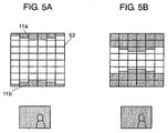
- Figs. 5A and 5B show light-shielding states of second lens array 52 by diaphragm mechanism 1 and projected images at that time.
- Fig. 5A shows a state where the diaphragm value is small
- Fig. 5B shows a state where the diaphragm value is large.
- end positions, which correspond to respective cells, of diaphragm blades 11a and 11b are different in such a manner that second lens array 52 has different light-shielded areas of the cells which are light-shielded by diaphragm blades 11a and 11b.
- Fig. 6 shows relation between a light-shielding state of each lens cell of second lens array 52 by diaphragm mechanism 1 and a projected image.
- a plurality of images of the light source formed on each lens cell on second lens array 52 are superimposed and emitted to liquid crystal panel 55, so that illuminance on the liquid crystal panel improves in uniformity.
- illuminance on the liquid crystal panel becomes uniform as described hereinafter.
- Lens cell 201 illuminates 2/3 of an upper side of the liquid crystal panel, and 1/3 of a lower side thereof is light-shielded.
- Lens cell 202 illuminates 1/3 of an upper side of the liquid crystal panel, and 2/3 of a lower side thereof is light-shielded.
- Whole lens cell 203 is light-shielded.
- Rectangles 211, 212 and 213 corresponding to liquid crystal panels schematically show states where the liquid crystal panel is illuminated by lens cells 201, 202 and 203. Therefore, rectangles 211, 212 and 213 also schematically show projected images.
- lens cell 206 illuminates 2/3 of an upper side of the liquid crystal panel, and 1/3 of a lower side thereof is light-shielded.
- Lens cell 205 illuminates 1/3 of an upper side of the liquid crystal panel, and 2/3 of a lower side thereof is light-shielded.
- Whole lens cell 204 is light-shielded.
- the whole liquid crystal panel is illuminated by combination of lens cell 201 and lens cell 245.
- the whole liquid crystal panel is illuminated by combination of lens cell 202 and lens cell 246.
- the liquid crystal panel is not illuminated by combination of lens cell 203 and lens cell 204.
- the whole liquid crystal panel is illuminated by combination of lens cell 241 and lens cell 205.
- the whole liquid crystal panel is illuminated by combination of lens cell 242 and lens cell 206.
- the liquid crystal panel is not illuminated by combination of lens cell 243 and lens cell 244.
- Illuminance decreases uniformly by amount of shielded light, so that liquid crystal panel 55 is illuminated uniformly.
- a position of a border between a light-shielded dark part and a bright part differs with cells, so that a border between brightness and darkness of each cell is not conspicuous at a projected image.
- diaphragm mechanism 1 in a case where diaphragm mechanism 1 is positioned between first lens array 51 and light source 50, if second lens array 52 is exchanged to first lens array 51 in the above discussion, the same effect can be obtained. Accordingly, diaphragm mechanism 1 may be placed between first lens array 51 and light source 50.
- Fig. 7A shows a light-shielding state of second lens array 52 by diaphragm mechanism 1 having a blade shape different from that of Fig. 5 and its projected image.
- liquid crystal panel 55 is illuminated uniformly. Accordingly illuminance decreases uniformly in the projected plane by amount of shielded light.
- Fig. 7B showing that the diaphragm value is large, illuminance more decreases uniformly than that of Fig. 7A without deteriorating quality of a projected image.
- Fig. 8A shows a light-shielding state of second lens array 52 by diaphragm mechanism 1 having a wing shape different from that of Figs. 5A, 5B, 7A and 7B and its projected image.
- liquid crystal panel 55 is illuminated uniformly. Accordingly illuminance decreases uniformly in the projected plane by amount of shielded light.
- Fig. 8B showing that the diaphragm value is large, illuminance more decreases uniformly than that of Fig. 8A without deteriorating quality of a projected image.
- liquid crystal panel 55 may be illuminated non-uniformly. However, even in that case, a projected plane is illuminated substantially uniformly.
- a position of a border between a light-shielded dark part and a bright part differs with cells, so that a border between brightness and darkness of each cell is not conspicuous at a projected image.
- Figs. 9A and 9B are front views showing light-shielded second lens arrays and their projected images.
- Fig. 9A shows a state where the diaphragm value is small
- Fig. 9B shows a state where the diaphragm value is large.
- diaphragm blades 11c and 11d are formed as a straight line.
- areas to be light-shielded by respective cells of the second lens arrays becomes equal one another, so that borders between brightness and darkness of respective cells correspond with one another at a projected image formed by superimposing. Therefore, non-uniformity of brightness is generated at positions indicated by arrows 301, 302, 303 and 304 in Figs. A and B.
- a position having non-uniformity of brightness of the projected image moves in response to positions of diaphragm blades 11c and 11d. Therefore, quality of the projected image deteriorates remarkably.
- diaphragm blades 11a and 11b is formed in such a manner that the second lens array has different light-shielded areas of the cells which are light-shielded by diaphragm blades 11a and 11b.
- illuminance changes substantially uniformly at the projected plane. Accordingly, even when brightness of the projected image changes continuously, high dynamic ranges with natural images can be obtained.
- a shape of diaphragm blade is not limited to the shape shown in Figs. 5A, 5B, 7A, 7B, 8A and 8B. Another shape is acceptable, if brightness of the projected image changes continuously and uniformly according to changing of the light-shielded area of the diaphragm blade.
- a shape of diaphragm blades 11a and 11b is a stepwise shape formed by straight lines.
- a shape of the diaphragm blade may be formed by a smooth curve shown in Figs. 10A, 10B and 10C in response to the shape of the diaphragm blade of Figs. 5A, 5B, 7A, 7B, 8A and 8B.
- the diaphragm blade may be formed using the shape combined by these curves.
- diaphragm blades 11a and 11b are formed in such a manner that opening 13 shows a vertically and horizontally symmetric shape.
- opening 13 may show a vertically and horizontally asymmetric shape.
- diaphragm blades may be formed of one piece.
- a reflection wavelength depends on an incident angle at dichroic mirrors 56G and 56R, so that non-uniformly of color is easy to occur slightly at the projected image when opening 13 has a vertically and horizontally asymmetric shape. Therefore, a vertically and horizontally symmetric shape or a point symmetric shape with respect to a center of the opening is preferable.
- diaphragm mechanism 1 is disposed between first lens array 51 and second lens array 52 is described.
- diaphragm mechanism 1 may be placed between first lens array 51 and light source 50.
- a pair of diaphragm mechanisms or a plurality of diaphragm mechanisms may be positioned at any one of positions of an optical path between lamp 50 and liquid crystal panel 55R, 55G or 55B.
- Fig. 11A is a top view showing an optical layout of a liquid crystal projector in this case.
- diaphragm mechanism 20 is disposed between first lens array 51 and second lens array 52 instead of diaphragm mechanism 1 shown in Fig. 1 discussed above.
- Fig. 11B is a sectional view showing a neighborhood of diaphragm mechanism 20.
- Fig. 12 is a perspective view of diaphragm mechanism 20.
- diaphragm blades 21a and 21b are coupled with each other by gears 22a and 22b, linked with a motor (not shown) and move.
- a gear ratio of gear 22a to gear 22b is set 1 to 1.
- Diaphragm blades 21a and 21b move vertically and symmetrically each other as shown at arrows 351 and 352 respectively.
- Fig. 12 shows a state where a diaphragm is opened.
- Diaphragm blades 21a and 21b perform an opening and closing operation in directions of arrows 351 and 352 shown in Fig. 12, so that a part of luminous flux emitted from lamp 50 is shielded.
- diaphragm blades 11a and 11b shown in Fig.4 diaphragm blades 21a and 21b each is formed as a stepwise shape in such a manner that a cell of a second lens array has different light-shielded area from another cell.
- this structure as this embodiment 1, brightness on a projected plane can be controlled uniformly without deteriorating quality of a projected image.
- diaphragm mechanism discussed before needs a space for storing the diaphragm blade outside the optical path, so that the diaphragm mechanism becomes large.
- diaphragm blades 21a and 21b can be stored between the first lens array and the second lens array, so that it is effective for saving spaces.
- diaphragm blades 11 and 21 Material having high reflectivity such as bright aluminum or material whose surface is plated with a material such as chrome having high reflectivity is preferably used at diaphragm blades 11 and 21.
- diaphragm blades 11 and 21 reflect light from lamp 50. Accordingly, heat-transfer to a driving section of diaphragm mechanism 1 or diaphragm mechanism 20 can be prevented. As a result, temperature-rise of the diaphragm mechanism and the driving section can be suppressed.
- a magnet used in the motor for driving diaphragm mechanism 1 or diaphragm mechanism 20 is demagnetized at a high temperature and its characteristics deteriorates. Therefore, by reducing a driving temperature of the driving section, stable driving characteristics of the motor can be obtained. Furthermore, by reducing the driving temperature, sufficient driving characteristics can be obtained even in a case of a motor using an inexpensive magnet, thereby making the apparatus at a low cost.
- a voice coil motor is preferably used as the motor for driving diaphragm mechanism 1 or diaphragm mechanism 20.
- the voice coil motor can work at a speed of response of 1/30 msec sufficiently, and thereby following luminance fluctuation of a moving image.
- the voice coil motor can control a stop position of the diaphragm blade without steps. Therefore, high dynamic ranges can be performed without deteriorating quality of a moving image.
- a liquid crystal projector is discussed.
- a projector using a micro mirror if it is a projection display apparatus adopting a method using a lens array to uniform a luminous flux from a lump, the present invention can be adapted.
- the projection display apparatus of the present invention using a simple diaphragm mechanism formed by a pair of diaphragm blades, a compact and low-cost projection display apparatus can be obtained. Furthermore, the projection display apparatus of the present invention can obtain high dynamic ranges. Therefore, the projection display apparatus of the present invention is useful as a projection display apparatus capable of controlling projection illuminance.
Abstract
Description
Claims (10)
- A projection display apparatus for expanding and projecting an image, which is formed by an optical modulator, using a projection lens comprising:wherein a traveling direction of the light emitted from the light source is defined as a Z-axis, a direction perpendicular to the Z-axis is defined as an X-axis, and a direction perpendicular to a plane formed by the Z-axis and the X-axis is defined as a Y-axis,a light source for illuminating the optical modulator;a first lens array for dividing light emitted from the light source into a plurality of partial luminous flux;a second lens array for superimposing the plurality of partial luminous fluxes emitted from the first lens array onto the optical modulator; anda diaphragm mechanism, which is disposed between the light source and the optical modulator, for controlling an amount of light from the light source,
wherein an area of an opening of the diaphragm mechanism changes in a direction of the X-axis or the Y-axis. - The projection display apparatus of claim 1,
wherein the diaphragm mechanism for controlling the amount of light is disposed between the first lens array and the second lens array. - The projection display apparatus of claim 1,
wherein the image formed by the optical modulator has a rectangular shape, and a short side direction of the rectangular shape of the image corresponds to the Y-axis,
wherein the area of the opening of the diaphragm mechanism changes in a direction of the Y-axis. - The projection display apparatus of claim 1,
wherein a center of the opening is located at a same position while a diaphragm value changes. - The projection display apparatus of claim 4,
wherein the opening has a point symmetric shape with respect to the center of the opening. - The projection display apparatus of claim 1,
wherein the diaphragm mechanism has a diaphragm blade or a pair of diaphragm blades both of which are positioned in the Y-axis direction with an interval, wherein respective areas of respective plural lenses included in the first lens array or the second lens array, which are light-shielded by the opening side portion of the diaphragm blade or each of the pair of diaphragm blades, include different areas. - The projection display apparatus of claim 6,
wherein the diaphragm blade or the each of the pair of diaphragm blades rotates about an end of a side thereof. - The projection display apparatus of claim 6,
wherein the diaphragm blade or each of the pair of diaphragm blades is made of material having high reflectivity. - The projection display apparatus of claim 6 further comprising:wherein the diaphragm blade or each of the pair of diaphragm blades is driven based on the detected brightness of the projected image in such a manner that a position of the diaphragm blade or a position of each of the pair of diaphragm blades is determined.a detector for detecting brightness of an image to be projected; anda driving section for driving the diaphragm blade or each of the pair of diaphragm blades,
- The projection display apparatus of claim 9,
wherein a voice coil motor is used as the driving section.
Applications Claiming Priority (3)
| Application Number | Priority Date | Filing Date | Title |
|---|---|---|---|
| JP2003318016 | 2003-09-10 | ||
| JP2003318016 | 2003-09-10 | ||
| PCT/JP2004/007897 WO2005026835A1 (en) | 2003-09-10 | 2004-06-01 | Projection display |
Publications (2)
| Publication Number | Publication Date |
|---|---|
| EP1569032A1 true EP1569032A1 (en) | 2005-08-31 |
| EP1569032A4 EP1569032A4 (en) | 2009-05-20 |
Family
ID=34308506
Family Applications (1)
| Application Number | Title | Priority Date | Filing Date |
|---|---|---|---|
| EP04735670A Withdrawn EP1569032A4 (en) | 2003-09-10 | 2004-06-01 | Projection display |
Country Status (5)
| Country | Link |
|---|---|
| US (1) | US7185990B2 (en) |
| EP (1) | EP1569032A4 (en) |
| JP (1) | JP4013979B2 (en) |
| CN (1) | CN100495197C (en) |
| WO (1) | WO2005026835A1 (en) |
Cited By (1)
| Publication number | Priority date | Publication date | Assignee | Title |
|---|---|---|---|---|
| EP1569468A3 (en) * | 2004-02-23 | 2006-11-15 | SANYO ELECTRIC Co., Ltd. | Shutter device and projection type video display |
Families Citing this family (42)
| Publication number | Priority date | Publication date | Assignee | Title |
|---|---|---|---|---|
| US6947025B2 (en) * | 2001-10-09 | 2005-09-20 | Seiko Epson Corporation | Lighting apparatus and projection type display, and driving method therefore |
| US7344255B2 (en) * | 2004-04-01 | 2008-03-18 | Nisca Corporation | Light amount adjusting apparatus and projector using the same |
| US7182470B2 (en) * | 2004-09-09 | 2007-02-27 | Nisca Corporation | Light amount control apparatus and projector apparatus using the same |
| TWI245965B (en) * | 2004-11-02 | 2005-12-21 | Young Optics Inc | Optical projection apparatus |
| TWI247963B (en) * | 2004-12-10 | 2006-01-21 | Hon Hai Prec Ind Co Ltd | A micro-mirror projector |
| TWI258019B (en) * | 2005-01-25 | 2006-07-11 | Benq Corp | Projection optical system |
| JP4823573B2 (en) * | 2005-06-08 | 2011-11-24 | 日本電産コパル株式会社 | Projector aperture device |
| JP4823574B2 (en) * | 2005-06-08 | 2011-11-24 | 日本電産コパル株式会社 | Projector aperture device |
| JP5002923B2 (en) * | 2005-08-09 | 2012-08-15 | 株式会社日立製作所 | Projection-type image display device |
| JP4904741B2 (en) | 2005-08-09 | 2012-03-28 | 株式会社日立製作所 | Projection-type image display device and shading method |
| JP4934303B2 (en) * | 2005-09-09 | 2012-05-16 | 三洋電機株式会社 | Projector device |
| JP4357469B2 (en) * | 2005-09-09 | 2009-11-04 | 三洋電機株式会社 | Projector device |
| JP4886254B2 (en) * | 2005-09-13 | 2012-02-29 | キヤノン株式会社 | Optical system and image projection apparatus |
| JP2007086690A (en) * | 2005-09-26 | 2007-04-05 | Victor Co Of Japan Ltd | Illumination optical system and projection type picture display device |
| JP5140914B2 (en) * | 2005-09-27 | 2013-02-13 | 株式会社Jvcケンウッド | Image display device |
| JP2007286391A (en) * | 2006-04-18 | 2007-11-01 | Matsushita Electric Ind Co Ltd | Illuminating device, illuminating method and projection type display apparatus using illuminating device |
| JP4197527B2 (en) | 2006-08-18 | 2008-12-17 | 三菱電機株式会社 | Projection display |
| JP2008096629A (en) * | 2006-10-11 | 2008-04-24 | Chinontec Kk | Diaphragm blade, diaphragm device and projection type display device |
| JP2008209811A (en) * | 2007-02-28 | 2008-09-11 | Hitachi Ltd | Display device and projection type illuminating device |
| JP5100430B2 (en) * | 2007-06-05 | 2012-12-19 | 三菱電機株式会社 | Projection display |
| CA2631144C (en) | 2007-06-05 | 2011-03-15 | Mitsubishi Electric Corporation | Projection display |
| JP4076573B1 (en) | 2007-06-08 | 2008-04-16 | 三菱電機株式会社 | Projection display |
| JP5013259B2 (en) | 2007-09-06 | 2012-08-29 | ミネベア株式会社 | Light diaphragm device |
| JP2010008767A (en) * | 2008-06-27 | 2010-01-14 | Hitachi Ltd | Optical unit and projection type video display |
| JP5334494B2 (en) * | 2008-08-20 | 2013-11-06 | 三菱電機株式会社 | Projection display |
| JP5298698B2 (en) * | 2008-08-20 | 2013-09-25 | パナソニック株式会社 | Projection display |
| JP5380028B2 (en) | 2008-09-25 | 2014-01-08 | 日立コンシューマエレクトロニクス株式会社 | Projection-type image display device and projection method |
| CN101726975B (en) * | 2008-10-20 | 2012-05-30 | 鸿富锦精密工业(深圳)有限公司 | Optical shutter and projector using the same |
| JP4766119B2 (en) * | 2009-01-28 | 2011-09-07 | セイコーエプソン株式会社 | projector |
| JP5212161B2 (en) | 2009-02-18 | 2013-06-19 | セイコーエプソン株式会社 | projector |
| JP4670977B2 (en) * | 2009-03-11 | 2011-04-13 | セイコーエプソン株式会社 | projector |
| CN102472952A (en) * | 2009-07-17 | 2012-05-23 | Nec显示器解决方案株式会社 | Diaphragm control circuit, projector device, diaphragm control program, and diaphragm control method |
| JP5440086B2 (en) * | 2009-10-13 | 2014-03-12 | セイコーエプソン株式会社 | projector |
| JP5509845B2 (en) * | 2009-10-27 | 2014-06-04 | セイコーエプソン株式会社 | projector |
| JP5316510B2 (en) * | 2010-10-26 | 2013-10-16 | 株式会社Jvcケンウッド | Projection display |
| US9703184B2 (en) * | 2011-08-12 | 2017-07-11 | Seiko Epson Corporation | Dimmer and projector |
| JP5798196B2 (en) | 2011-11-07 | 2015-10-21 | 日立マクセル株式会社 | Projection display device |
| CN106249519A (en) * | 2016-08-22 | 2016-12-21 | 深圳市华星光电技术有限公司 | A kind of projector |
| JP6717125B2 (en) * | 2016-09-01 | 2020-07-01 | 株式会社Jvcケンウッド | Light emitting device and projection type image display device |
| JP6460088B2 (en) * | 2016-12-14 | 2019-01-30 | カシオ計算機株式会社 | Projection apparatus, projection method, and program |
| CN113126409B (en) * | 2019-12-30 | 2023-08-11 | 深圳光峰科技股份有限公司 | Projection display system |
| WO2023219766A1 (en) * | 2022-05-11 | 2023-11-16 | Dolby Laboratories Licensing Corporation | Fast opto-mechanical attenuator for high-power projector systems |
Citations (4)
| Publication number | Priority date | Publication date | Assignee | Title |
|---|---|---|---|---|
| JPH11281923A (en) * | 1998-03-30 | 1999-10-15 | Mitsubishi Electric Corp | Projection display device |
| JP2001222002A (en) * | 2000-02-10 | 2001-08-17 | Sony Corp | Liquid crystal projector device |
| US20010015775A1 (en) * | 2000-02-18 | 2001-08-23 | Chikara Yamamoto | Illumination optical system and projection type display apparatus using the same |
| JP2003241311A (en) * | 2002-02-14 | 2003-08-27 | Seiko Epson Corp | Projector |
Family Cites Families (23)
| Publication number | Priority date | Publication date | Assignee | Title |
|---|---|---|---|---|
| JPS526174B2 (en) * | 1972-10-18 | 1977-02-19 | ||
| JPS539855B2 (en) * | 1973-11-21 | 1978-04-08 | ||
| JPS59651Y2 (en) * | 1980-10-17 | 1984-01-10 | 丸茂電機株式会社 | dimmer device |
| JPH0219012U (en) * | 1988-07-15 | 1990-02-08 | ||
| JP3182863B2 (en) | 1992-04-24 | 2001-07-03 | セイコーエプソン株式会社 | Projection display device |
| US5300967A (en) * | 1992-07-31 | 1994-04-05 | Mitsubishi Denki Kabushiki Kaisha | Projection exposure apparatus |
| US5924783A (en) * | 1997-07-24 | 1999-07-20 | Raychem Corporation | System for controlling contrast in projection displays |
| JP3379399B2 (en) * | 1997-08-26 | 2003-02-24 | ウシオ電機株式会社 | Shutter mechanism of light irradiation device |
| JPH11194383A (en) * | 1997-12-26 | 1999-07-21 | Canon Electron Inc | Light quantity adjusting device |
| JP2001100699A (en) | 1999-09-29 | 2001-04-13 | Canon Inc | Projection display device and its application system |
| JP4151211B2 (en) | 2000-09-12 | 2008-09-17 | セイコーエプソン株式会社 | projector |
| JP3832230B2 (en) * | 2000-11-14 | 2006-10-11 | ウシオ電機株式会社 | Light irradiation device |
| TW483531U (en) * | 2001-02-13 | 2002-04-11 | Delta Electronics Inc | Projector illuminous system having optical gobo |
| JP3610931B2 (en) | 2001-07-13 | 2005-01-19 | 日本ビクター株式会社 | Projection display |
| JP3992268B2 (en) * | 2001-09-28 | 2007-10-17 | フジノン株式会社 | Projection-type image display device |
| JP4282925B2 (en) * | 2001-11-20 | 2009-06-24 | パナソニック株式会社 | Projection display |
| JP3880436B2 (en) * | 2002-04-12 | 2007-02-14 | キヤノン株式会社 | Projection-type image display device |
| JP4158611B2 (en) * | 2002-09-06 | 2008-10-01 | 株式会社日立製作所 | Projection-type image display device |
| US6843591B1 (en) * | 2003-03-03 | 2005-01-18 | Rockwell Collins | Multiple lamp coupler |
| CN100371744C (en) * | 2003-05-21 | 2008-02-27 | Jds尤尼弗思公司 | System and method for providing a uniform source of light |
| US6769777B1 (en) * | 2003-08-20 | 2004-08-03 | Honeywell International Inc. | Multi-aperture optical dimming system |
| US20050135761A1 (en) * | 2003-12-23 | 2005-06-23 | Cannon Bruce L. | Optical element for uniform illumination and optical system incorporating same |
| US7090357B2 (en) * | 2003-12-23 | 2006-08-15 | 3M Innovative Properties Company | Combined light source for projection display |
-
2004
- 2004-06-01 JP JP2005513811A patent/JP4013979B2/en active Active
- 2004-06-01 CN CNB2004800017191A patent/CN100495197C/en active Active
- 2004-06-01 US US10/537,979 patent/US7185990B2/en active Active
- 2004-06-01 EP EP04735670A patent/EP1569032A4/en not_active Withdrawn
- 2004-06-01 WO PCT/JP2004/007897 patent/WO2005026835A1/en active Application Filing
Patent Citations (4)
| Publication number | Priority date | Publication date | Assignee | Title |
|---|---|---|---|---|
| JPH11281923A (en) * | 1998-03-30 | 1999-10-15 | Mitsubishi Electric Corp | Projection display device |
| JP2001222002A (en) * | 2000-02-10 | 2001-08-17 | Sony Corp | Liquid crystal projector device |
| US20010015775A1 (en) * | 2000-02-18 | 2001-08-23 | Chikara Yamamoto | Illumination optical system and projection type display apparatus using the same |
| JP2003241311A (en) * | 2002-02-14 | 2003-08-27 | Seiko Epson Corp | Projector |
Non-Patent Citations (1)
| Title |
|---|
| See also references of WO2005026835A1 * |
Cited By (2)
| Publication number | Priority date | Publication date | Assignee | Title |
|---|---|---|---|---|
| EP1569468A3 (en) * | 2004-02-23 | 2006-11-15 | SANYO ELECTRIC Co., Ltd. | Shutter device and projection type video display |
| US7338174B2 (en) | 2004-02-23 | 2008-03-04 | Sanyo Electric Co., Ltd. | Shutter device and projection type video display |
Also Published As
| Publication number | Publication date |
|---|---|
| WO2005026835A1 (en) | 2005-03-24 |
| CN100495197C (en) | 2009-06-03 |
| US20060050248A1 (en) | 2006-03-09 |
| US7185990B2 (en) | 2007-03-06 |
| CN1723415A (en) | 2006-01-18 |
| JPWO2005026835A1 (en) | 2006-11-24 |
| EP1569032A4 (en) | 2009-05-20 |
| JP4013979B2 (en) | 2007-11-28 |
Similar Documents
| Publication | Publication Date | Title |
|---|---|---|
| US7185990B2 (en) | Projection display apparatus | |
| US7417618B2 (en) | Lighting apparatus and projection type display, and driving method therefor | |
| CN1181389C (en) | Projective image display device | |
| JP4259567B2 (en) | Projector, projection system, program, and recording medium | |
| US8000019B2 (en) | Optical system for a display panel using divided irradiation | |
| US7825362B2 (en) | Projection device having a lens adjusting unit adjusting a focus of an adjustable collimator according to the distance between a light source and the adjustable collimator | |
| JPH10260375A (en) | Liquid crystal projector and its driving method | |
| JP2008249747A (en) | Integrator unit | |
| TW201337436A (en) | Color wheel module for use in a projector apparatus, projector apparatus, and method of switching display for a stereoscopic image or a flat image | |
| JP5298698B2 (en) | Projection display | |
| KR100672506B1 (en) | Project device in Projector | |
| JPH10206813A (en) | Liquid crystal projector and driving method therefor | |
| KR20040009312A (en) | Lcd projector using led | |
| JP2005107375A (en) | Screen, projector system and rear projector | |
| JP2006293124A (en) | Projector | |
| US20060203132A1 (en) | Device and method of color adjustment for projection type video image display devices | |
| KR0179105B1 (en) | Lcd projector | |
| KR20070021253A (en) | Illuminator and projection display and its driving method | |
| JP2009204879A (en) | Projection video display device | |
| JP2007148105A (en) | Projector | |
| JP2012155119A (en) | Projector | |
| JP2006184588A (en) | Image display apparatus |
Legal Events
| Date | Code | Title | Description |
|---|---|---|---|
| PUAI | Public reference made under article 153(3) epc to a published international application that has entered the european phase |
Free format text: ORIGINAL CODE: 0009012 |
|
| 17P | Request for examination filed |
Effective date: 20050607 |
|
| AK | Designated contracting states |
Kind code of ref document: A1 Designated state(s): AT BE BG CH CY CZ DE DK EE ES FI FR GB GR HU IE IT LI LU MC NL PL PT RO SE SI SK TR |
|
| AX | Request for extension of the european patent |
Extension state: AL HR LT LV MK |
|
| DAX | Request for extension of the european patent (deleted) | ||
| RBV | Designated contracting states (corrected) |
Designated state(s): DE FR GB |
|
| RAP1 | Party data changed (applicant data changed or rights of an application transferred) |
Owner name: PANASONIC CORPORATION |
|
| A4 | Supplementary search report drawn up and despatched |
Effective date: 20090421 |
|
| RIC1 | Information provided on ipc code assigned before grant |
Ipc: H04N 9/31 20060101ALI20090415BHEP Ipc: G03B 21/14 20060101AFI20050401BHEP |
|
| 17Q | First examination report despatched |
Effective date: 20100301 |
|
| GRAP | Despatch of communication of intention to grant a patent |
Free format text: ORIGINAL CODE: EPIDOSNIGR1 |
|
| GRAC | Information related to communication of intention to grant a patent modified |
Free format text: ORIGINAL CODE: EPIDOSCIGR1 |
|
| STAA | Information on the status of an ep patent application or granted ep patent |
Free format text: STATUS: THE APPLICATION IS DEEMED TO BE WITHDRAWN |
|
| 18D | Application deemed to be withdrawn |
Effective date: 20110319 |