Background of the invention
1. Field of the invention
This invention relates to endless tracks used to propel track-laying vehicles [i.e., vehicles
which use endless tracks rather than tires to contact the terrain over which they are driven,
e.g., tractors, tanks, bulldozers, etc.] and, more particularly, to an improved rubber track
design allowing the endless track to be driven more efficiently at highway speeds:
2. General discussion
Numerous types of vehicles are frequently used in terrain in which it is difficult for
pneumatic tires to operate. Both military vehicles, such as tanks and amphibious vehicles,
and civilian vehicles, such as tractors and recreational vehicles, are sometime utilized on
terrains which are very soft, for example sand surfaces. Pneumatic tires are not capable
of efficient operation on such soft surfaces, as they tend to burrow into the surface, rather
than riding across the surface.
Endless track vehicles have been developed for use on terrains in which pneumatic-tired
vehicles are impractical. See for example U.S. Patents 3,361,488 (Ohm et al), 3,688,858
(Jespersen), 3,734,577 (Snellman) and 3,955,855 (Massieon et al). In many types of
terrain these vehicles provide improved performance relative to the performance of
pneumatic-tired vehicles; still, difficulties are encountered with existing endless track
vehicles.
Originally, such tracks were made of a plurality of metal links or shoes pivotally attached
to each other to form an endless track which are very heavy, cause serious damage to
roads and other surfaces on which they run and result in an uncomfortable ride for the
passengers. See for example U.S. Patents 2,823,082 (Bauer) and 4,530,546 (Meisel, Jr.).
Heavier vehicles still use metal tracks.
The above-referenced conventional tracks have the disadvantages of being noisy and
vibration prone, not sufficiently durable and/or not usable on road surfaces. This is
because of the conventional configurations and use of metal parts. Accordingly, substantial
efforts have been made to construct quieter, smoother operating and more durable tracks
for tracked vehicles.
A need has developed for a form of vehicle appropriate for both normal highway use and
off-road use over snow-covered, very uneven, or muddy terrain. There is significant need
for such a vehicle not only during armed conflicts but also following natural emergencies
(snow and wind storms, floods, etc.), and such vehicles are at present particularly needed
in developing countries. Unfortunately, almost all available automotive vehicles require
infrastructure (paved highways, bridges, etc.) for practical operation, and the developing
countries are decades awayfrom having the necessary infrastructure for such conventional
vehicles. Further, most load-carrying off-road vehicles presently in use have either very
large wheels or very cumbersome tracks which are heavy, slow moving, and inappropriate
for use on paved roads at normal highway speeds.
Rubber endless tracks have become popular due to an increase in construction in urban
areas where vehicles having tracks must drive on the pavement and because there is a
demand for low soil compaction farming. With the combination of rubber technology and
a tremendous amount of trial and error, various types of rubber tracks are now available
in the industry. They are used on excavators, dump carriers, boring machines, combines,
tractors, and the like See for example U.S. Patents 5,279,378 (Graiwey & al) and
6,267,458 (Hansen et al). Most of them operate on the job site only and are transported
between sites by trucks or trailers. To eliminate the inconvenience of transporting the
vehicle between job sites, a vehicle which can operate both on public roads at normal
speeds and in off-road construction environments is required. However, such a vehicle will
have to be constructed so as to provide little damage to the pavement, include less
vibration and noise, and operate with less maintenance and lubrication. Furthermore,
vibrations to be transmitted to occupants are mitigated and paved roads are not
significantly damaged.
A number of hybrid tracks have been proposed where the links or shoes are made of metal
which is provided with a rubber cover or insert. See for example U.S. Patents 2,359,586
(Sayler), 2,369,130 (Benson), 2,409,502 (Leguillon et al), 3,148,921 (Batur et al),
4,109,971 (Black et al), 4,359,248 (Kortering) and 4,588,233 (DenBesten).
3. Description of the related art
[NOTE: As used herein, the term "rubber" relates to any elastic and primarily non-metallic
materials such as rubber, elastomers, or combinations thereof used in the manufacture of
endless tracks].
Most rubber tracks are formed around a basic carcass or belt. The carcass includes an
endless belt-shaped rubber-like elastic member, a number of core bars (usually of metal)
embedded therein and aligned in the longitudinal direction thereof and extending in
traverse directions thereof, and steel cords (tension-resistant members) embedded in the
endless elastic member to surround the core bars circumferentially outwardly. See for
example U.S. Patents 4,904,030 (Ono), 5,295,741 (Togashi et al), 5,511,869 (Edwards et
al) and 6,241,327 (Gleasman).
Some have suggested the construction of endless rubber tracks using a plurality of
interconnected polymeric modules. See for example U.S. Patents 4,861,120 (Edwards et
al) 5,005,922 (Edwards et al).
Terrain-contacting lugs are formed integral with the exterior surface of this basic belt
element. Known rubber tracks include large lugs having a variety of well-known
orientations, e.g., formed generally perpendicular to the track axis, or at an angle to the
track axis, or in a chevron or modified-chevron design. These latter special tracks also
include interior lugs or horns for maintaining the track in alignment as it travels over the
circumferences of the rubber-tired wheels, such lugs being located either in the centre of
the interior surface of the track (for designs appropriate for fitting between the tires of
dual-wheels) or in two aligned rows near the outside edges of the track (for receiving a
single tire there between). See for example U.S. Patent 5,447,365 (Muramatsu & al) and
5,540,489 (Muramatsu & al).
The tracks are carried by a plurality of rotating elements (wheels, sprockets, etc...)
mounted on the track-laying vehicle, the tracks being maintained in circumferential contact
with these rotating elements and being driven thereby (or, in the case of trailer-like
non-driven vehicles, being supported for rotation thereon).
Problems encountered in actually reducing such an endless rubbertrack to practice include
how to maintain adequate tension on such belt, how to drive such tracks and keeping the
belt in lateral alignment with the wheels when the wheels are subject to large lateral loads.
Other problems are maintaining the structural integrity and providing long life for the belt,
mid-rollers, drive wheels, and idler wheels.
While smaller rubber tracked vehicles are commercially available, these do not carry
adequate loads for military vehicles (including tanks), normal multi-passenger or produce
transport, and their drive wheels can easily become mired in heavy mud or snow.
As stated in U.S. Patent 5,295,741 (Togashi et al), when a vehicle equipped with rubber
tracks moves on sandy terrain or quarries, the rubber tracks are likely to shift from
advancing directions of the vehicle due to elongations and contractions of the rubber-like
material in vertical and horizontal and other directions. As a result, the rubber tracks
unavoidably get off the sprocket wheels or track rollers of the vehicle. Various attempts
have been made in orderto prevent the dislodgement of the rubbertracks from the vehicle,
but they have not met with success.
Known rubber tracks, when mounted on the rotating wheels of vehicles, exert distinct
resistive forces that must be overcome to move the vehicle, i.e., resistive forces in addition
to those forces created by the load being carried and/or generated by the terrain. These
further resistive forces relate to the additional tensions required to stretch the heavy lugs
of the tracks around the wheels over which they are mounted and to the additional friction
generated between the tracks and the terrain. While the latter frictional resistive forces are
a valuable attribute under wet or snowy conditions, they add undesirably to energy costs
when driving the vehicle over flat, hard surfaces.
The aforementioned patents are representative of a large body of patents which purport
to solve one or more of the rubber track system implementation problems. Such body of
patents constitutes documentary evidence that efforts to achieve this blend of track and
wheel propulsion systems have been exerted for over half a century without realizing any
practical measure of success. Solutions to the problems of actually implementing a
heavy-duty vehicular rubber track drive system have proven elusive and scientific scaling
techniques have not, to date, been successfully applied to light duty vehicles for purposes
of developing a heavy-duty rubber track system. Thus, despite the long felt need for and
the advantages thereof, a heavy-duty application vehicle utilizing such rubbertrack system
is commercially unavailable today.
Forthis reason, most military tracked vehicles are still equipped with metallic tracks. In an
effort to reduce the inconveniences related to such metallic track systems, some tracks are
provided with rubber pads on the ground engaging side of the metallic track.
However, these metallic tracks still present significant inconveniences in relation to
wheeled vehicle. Some of these problems can be summarized as follows:
- Noise. The metallic track produces an excessively high level of noise. This fact can
cause a significant strategic disadvantage when used in association with military
vehicles since the enemy can detect the presence of the military vehicle many miles
away.
- Damage. With respect to civilian vehicles equipped with such tracks or military
vehicles used in peace keeping missions, the metallic tracks can cause significant
damage to the ground surface whether it be paved or not.
- Weight. Metallic tracks are very heavy. For example the typical weight of a metallic
track used on an M113 tank is 544 kg (1200 pounds)while the metallic track used on a
Bradley tank is 1134 kg (2500 pounds). Such a weight is both an inconvenience with respect
to the mobility of the vehicles and with respect to their consumption of fuel.
- Short lifespan. Metallic tracks have a short lifespan. Even metallic tracks provided
with rubber pads wear out.extremely rapidly such that the pads need to be replaced
every 800 to 1600 km (500 to 1000 miles) on a military tank.
- Maintenance. Metallic tracks also require a lot of maintenance. The replacement
of the rubber pads, the metallic links or shoes, etc. requires a continuous
maintenance of the tracks.
- Costs. Finally, the cost of manufacturing, maintenance and refurbishing are
extremely high.
As seen above, efforts to develop a rubber alternative to metallic tracks have been
relatively successful in relation to "light" vehicles. However, such rubber tracks, although
an improvement in many respects over the known metallic tracks still have the following
shortcomings in relation to heavy equipment such as tanks:
- De-tracking. De-tracking is a phenomenon by which a track loses contact with the
guiding system such that it will completely remove itself from the vehicle and thus
cause it to stop. To limit this phenomenon, more or less rigid protuberances or
guide horns are disposed along the interior portion of the track to form a rampart
which fits between guide wheels. These wheels are generally grouped in pairs and
the space between the wheels allows the guide horns to past freely between them.
Another element which is important to reduce de-tracking is the use of an
appropriate tension wheel.
- Teeth Skipping. Tracks are powered by a motor mechanically connected to a
sprocket which engages protuberances or drive lugs on the inside surface of the
track. If these drive lugs are allowed to skip over the teeth of the sprocket,
damages to and premature wear of the track will occur. The abrupt movements
which result also cause significant discomfort to the passengers of the vehicle. In
order to diminish such teeth skipping phenomenon, the drive lugs on the track must
produce as small a friction as possible on the sprocket while allowing the sprocket
to firmly engage the track. Again, tensioning of the track is a critical element.
- Wear and tear. Tracks can also prematurely break down due to a number of other
internal and external elements such as: breakage of reinforcing rods, tearing of the
reinforcing fabric, cables and fibres and the abrasion, piercing, tearing and delamination
of the rubber components.
The prior art solutions which are adapted for industrial and agricultural vehicles are
inadequate when faced with the severity of the problems faced by military vehicles.
Indeed, the high weight of military vehicles combined to the high speeds and strong
accelerations (both lateral and longitudinal) create high stresses in the track which
considerably amplify the aforesaid problems.
Summary of the invention
It is, thus, the objective of this invention to provide a workable solution to the problems by
taking into account that such vehicle's u'ndercarriage, to be truly useful, should be
roadable, provide high traction and low ground compression, and minimally disturb the
underlying terrain, as well as operate in the heavy-duty working mode and provide a
smooth ride for the operator in most soil conditions and topography from level land to steep
inclinations while performing useful work without breaking the belts, losing drive capability
between engaged wheels and belts, or disengaging the belts from the wheels.
It is an object of the present invention to reduce such de-tracking, teeth skipping and wear
and tear on all types of vehicles (military, industrial, agricultural and others).
It is another object of the present invention to replace metallic tracks by a reinforced
rubber track which provides the advantages of metallic tracks (including good traction,
support and adaptability to all types of terrain) while diminishing significantly the
disadvantages (noise, damage to the ground surface, weight, short lifespan, maintenance
and high costs).
There is therefore provided a track for use on a tracked vehicle made from a polymer
adapted to travel over a drive sprocket, a plurality of guide wheels and a tensioning wheel,
said track having a first exterior ground engaging surface and a second interior drive
sprocket engaging surface, said track comprising:
- a carcass portion in which reinforcing means are embedded into said
polymer;
- a plurality of tread lugs disposed on said first engaging surface;
- a plurality of drive lugs, also referred to as traction lugs disposed on said second engaging surface;
- a plurality of drive horns, also referred to as guide horns, disposed on said second engaging surface, each
said drive horn having: a forward surface, a rear surface and two lateral
surfaces;
wherein the upper forward portion of each said lateral surface is bevelled.
There is also provided a track for use on a tracked vehicle made from a polymer adapted
to travel over a drive sprocket, a plurality of guide wheels and a tensioning wheel, said
track having a first exterior ground engaging surface and a second interior drive sprocket
engaging surface, said track comprising:
- a carcass portion in which reinforcing means are embedded into said
polymer;
- a plurality of tread lugs disposed on said first engaging surface;
- a plurality of drive lugs disposed on said second engaging surface;
- a plurality of drive horns disposed on said second engaging surface;
wherein said sprocket drive is made of a polymer providing a high abrasion
resistance and low friction.
There is also provided a track for use on a tracked vehicle made from a polymer adapted
to travel over a drive sprocket having an outer perimeter, a plurality of guide wheels and
a tensioning wheel, said track having a first exterior ground engaging surface and a second
interior drive sprocket engaging surface, said track comprising:
- a carcass portion in which reinforcing means are embedded into said
polymer;
- a plurality of tread lugs disposed on said first engaging surface;
- a plurality of drive lugs disposed on said second engaging surface;
- a plurality of drive horns disposed on said second engaging surface;
wherein said sprocket comprises a plurality of sockets disposed along said
perimeter, each socket being adapted to drivingly engage one of said drive lugs and
said perimeter having a polygonal configuration when viewed from one of its lateral
sides.
There is also provided a track for use on a tracked vehicle made from a polymer adapted
to travel over a drive sprocket, a plurality of guide wheels and a tensioning wheel, said
track having a first exterior ground engaging surface and a second interior drive sprocket
engaging surface, said track comprising:
- a carcass portion in which reinforcing means are embedded into said
polymer;
- a plurality of tread lugs disposed on said first engaging surface;
- a plurality of drive lugs disposed on said second engaging surface;
- a plurality of drive horns disposed on said second engaging surface, each
said drive horn having a forward surface, a rear surface and two lateral
surfaces;
wherein said guide wheels comprise two track supporting outer surfaces between which
the said guide horns are adapted to pass, each outer surfaces defining a first gap between
it and said guide horns and a second gap between it and said drive lugs, said second gap
being greater than said first gap.
In another embodiment, the sprocket is provided with:
- an outer perimeter having a polygonal configuration when viewed from one
of its lateral sides;
- a plurality of cavities disposed along said perimeter, each adapted to
engagingly mate with one of said drive lugs; and
- a track engaging surface located along said perimeter.
While the invention is applicable to endless tracks for all track-laying vehicles, its particular
purpose is to increase the efficiency of heavy track-laying all-terrain vehicles such as
military tanks that are specifically designed for normal speed travel over paved highways
as well as for appropriate use over unpaved roads and uneven off-road terrain.
Other aspects and many of the attendant advantages will be more readily appreciated as
the same becomes better understood by reference to the following detailed description and
considered in connection with the accompanying drawings in which like reference symbols
designate like elements throughout the figures.
The features of the present invention which are believed to be novel are set forth with
particularity in the appended claims.
Brief description of the drawings
Accordingly it is intended that the foregoing disclosure and showing made in the drawings
shall be considered only as an illustration of the principle of the present invention.
Detailed description of a preferred embodiment
FIG 1. shows a general side view of a rubber track system in accordance with this
invention installed on a military vehicle 10. The track system comprises an endless
reinforced rubber track 100, a sprocket drive 20, a tension wheel 30 and a plurality of guide
wheels 40 which support the vehicle and guide the track 100. This system is coupled to
appropriate drive means (not shown) through an appropriate suspension system (not
shown). A similar system is disposed on the other side of the vehicle 10.
As shown in FIG. 2, a track 100 is typically built around a belt like carcass 150 made of
reinforced rubber. As noted above, the term "rubber" relates to any appropriate elastic
polymer. The belt 100 comprises an external surface 200 and an internal surface 300. As
shown in FIG. 2, a plurality of traction lugs 210, 220 and 230 are disposed on the exterior
surface 200. These traction lugs or tread interact with the surface on which the vehicle
10 is being displaced to ensure appropriate traction of the vehicle. The traction lugs are
made out of a sufficient quality of rubber to support the normal wear of the tread due to
abrasion.
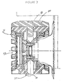
As shown in FIG. 3, the
interior surface 300 of the
track 100 comprises:
As illustrated in Figures 3 and 4, the guide lugs 320, the traction lugs 330 and the exterior
tread lugs 210, 220 and 230 are placed on the track in such a way as to form successive
segments each having an identical pitch 130. The various section are separated by
sections 110 of the carcass 150 on which no lug, horn or other protuberance is located
thus forming a hinge which will allow the track to wrap itself around the various wheels
forming the track system of this invention. When used in relation to a military tank such as
an M 113 tank, the pitch 130 is preferably between 50.8 mm (two inches) and 152,4 mm (six inches). However,
for a given sprocket diameter, it is preferable to reduce the pitch in order to increase the
number of drive lugs which at any given time are engaged into the sprocket cavities 23.
The minimum number of drive lugs 330 which are in contact with cavities 23 at any given
time is four.
In order to optimise the interaction between the track and the other components of the
track system to reduce de-tracking, skipping of teeth and wear and tear, it is preferable that
each component be optimised as described hereunder:
While a preferred embodiment of the invention has been described herein, it should be
apparent to those skilled in the art that variations and modifications are possible without
departing from the spirit of this invention.
The following elucidations provide further information with respect to the invention
or its relevant background:
wherein the upper forward portion of each said lateral surface is bevelled.
A sprocket for use on a track as defined above preferably comprises:
Preferably, there are at least 12 cavities.
Alternatively, there may be at least 15 cavities.
Further alternatively, said cavities are disposed on both sides of the sprocket.
Further alternatively, at least 12 said cavities are disposed on each side of the
sprocket.
Further alternatively, at least 15 said cavities are disposed on each side of the
sprocket.
When said cavities are disposed on both sides of the sprocket, preferably, a gorge
adapted to receive said guide horns is disposed near the center of the track engaging
surface.
Also, when said cavities are disposed on both sides of the sprocket, preferably, a v-shaped
gorge adapted to receive said guide horns is disposed near the center of
the track engaging surface.
A track for use on a tracked vehicle made from a polymer adapted to travel over a
drive sprocket, a plurality of guide wheels and a tensioning wheel, said track having
a first exterior ground engaging surface and a second interior drive sprocket engaging
surface may also comprise:
wherein said sprocket drive is made of a polymer providing a high abrasion resistance
and low friction.
Said polymer may be an ultra high molecular weight polyethylene.
A track for use on a tracked vehicle made from a polymer adapted to travel over a
drive sprocket having an outer perimeter, a plurality of guide wheels and a tensioning
wheel, said track having a first exterior ground engaging surface and a second
interior drive sprocket engaging surface may also comprise:
wherein said sprocket comprises a plurality of sockets disposed along said perimeter,
each socket being adapted to drivingly engage one of said drive lugs and said
perimeter having a polygonal configuration when viewed from one of its lateral
sides.
Preferably, at least four drive lugs are engaged in said sockets at any given time.
Also, preferably, at least four consecutive drive lugs are engaged in said socket at
any given time.
Further preferably, said track is comprised of a plurality of longitudinally extending
sections, each section being attached to adjoining sections only by said carcass
portion.
Also, the longitudinal extent of each said section may be equal to the length of each
side of said polygonal perimeter.
Alternatively, the longitudinal extent of each said section may be equal to 99 % to
100 % of the length of each side of said polygonal perimeter.
A track for use on a tracked vehicle made from a polymer adapted to travel over a
drive sprocket, a plurality of guide wheels and a tensioning wheel, said track having
a first exterior ground engaging surface and a second interior drive sprocket engaging
surface may also comprise:
wherein said guide wheels comprise two track supporting outer surfaces between
which the said guide horns are adapted to pass, each outer surfaces defining a first
gap between it and said guide horns and a second gap between it and said drive
lugs, said second gap being greater than said first gap.
A track system for use on a heavy tracked vehicle may also comprise:
Preferably, each of said drive sprockets, guide wheels and tensioning wheels are
provided with a gorge or groove on their outside perimeter said groove or gorge being
adapted to receive said guide horns.
Alternatively, each of said drive sprocket, guide wheels and tensioning wheels are
provided with an annular running surface on their outside perimeter, said running
surface being adapted to run over said first flat surface.