EP1564004A1 - An Ink Cartridge - Google Patents
An Ink Cartridge Download PDFInfo
- Publication number
- EP1564004A1 EP1564004A1 EP05100917A EP05100917A EP1564004A1 EP 1564004 A1 EP1564004 A1 EP 1564004A1 EP 05100917 A EP05100917 A EP 05100917A EP 05100917 A EP05100917 A EP 05100917A EP 1564004 A1 EP1564004 A1 EP 1564004A1
- Authority
- EP
- European Patent Office
- Prior art keywords
- drive substrate
- ink cartridge
- head
- cable
- head cable
- Prior art date
- Legal status (The legal status is an assumption and is not a legal conclusion. Google has not performed a legal analysis and makes no representation as to the accuracy of the status listed.)
- Withdrawn
Links
Images


Classifications
-
- B—PERFORMING OPERATIONS; TRANSPORTING
- B41—PRINTING; LINING MACHINES; TYPEWRITERS; STAMPS
- B41J—TYPEWRITERS; SELECTIVE PRINTING MECHANISMS, i.e. MECHANISMS PRINTING OTHERWISE THAN FROM A FORME; CORRECTION OF TYPOGRAPHICAL ERRORS
- B41J2/00—Typewriters or selective printing mechanisms characterised by the printing or marking process for which they are designed
- B41J2/005—Typewriters or selective printing mechanisms characterised by the printing or marking process for which they are designed characterised by bringing liquid or particles selectively into contact with a printing material
- B41J2/01—Ink jet
- B41J2/17—Ink jet characterised by ink handling
- B41J2/175—Ink supply systems ; Circuit parts therefor
- B41J2/17503—Ink cartridges
- B41J2/17526—Electrical contacts to the cartridge
-
- B—PERFORMING OPERATIONS; TRANSPORTING
- B41—PRINTING; LINING MACHINES; TYPEWRITERS; STAMPS
- B41J—TYPEWRITERS; SELECTIVE PRINTING MECHANISMS, i.e. MECHANISMS PRINTING OTHERWISE THAN FROM A FORME; CORRECTION OF TYPOGRAPHICAL ERRORS
- B41J2/00—Typewriters or selective printing mechanisms characterised by the printing or marking process for which they are designed
- B41J2/005—Typewriters or selective printing mechanisms characterised by the printing or marking process for which they are designed characterised by bringing liquid or particles selectively into contact with a printing material
- B41J2/01—Ink jet
- B41J2/17—Ink jet characterised by ink handling
- B41J2/175—Ink supply systems ; Circuit parts therefor
- B41J2/17503—Ink cartridges
- B41J2/1752—Mounting within the printer
Definitions
- the present invention relates an ink cartridge for a printer comprising a print head and a contact for receiving print head control signals.
- Inkjet printers can be classified into either shuttle type or array type inkjet printers.
- Shuttle type ink jet printers print using only one head chip.
- Array type inkjet printers print at high speed by using a plurality of head chips.
- Both shuttle and array type inkjet printers eject ink onto a print medium by using printing data transmitted from a host such as a computer to the head chip(s) which use this data to form an image.
- a host such as a computer
- head chip(s) which use this data to form an image.
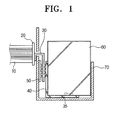
- a known arrangement for transmitting printing data is shown in Figure 1.
- a first cable 10, a drive substrate 20, a second cable 30 and a head cable 40 are typically used to transmit the printing data as described above to a head chip 35 on an ink cartridge 60.
- the first cable 10 is electrically connected to a main board (not shown) of the inkjet printer.
- the main board receives printing data from a host such as a computer.
- the main board transmits the printing data to the substrate 20.
- the printing data received by the drive substrate 20 is transmitted to the second cable 30 and the printing data received by the second cable 30 is fed to the head chip 35 of the ink cartridge 60 via the head cable 40.
- the head chip 35 ejects ink onto a printing medium (such as paper) according to the transmitted printing data, thereby forming an image.
- the head cable 40 is attached to the rear and bottom sides of the ink cartridge 60.
- the second cable 30 is in direct contact with the head cable 40 to establish an electrical connection.
- an elastic member 50 for compressing the second cable 30 is interposed between a carrier 70 of the ink cartridge 60 and the second cable 30.
- the elastic member 50 is fixed to the side of the printer.
- the printer may become useless if the elastic member 50 is hardened due to repeated or long-term use. Accordingly, the life span of the printer may be shortened.
- an improved printing apparatus having a simplified arrangement to transmit the printing data to a head chip.
- the simplified arrangement improves contact between the head cable and the drive substrate to prevent loss of the printing data.
- an object of the present invention is to provide an ink cartridge unit that reduces the number of components and simplifies the construction of the ink cartridge unit and an inkjet printer having the same.
- Another object of the present invention is to provide an inkjet printer with increased reliability.
- Still another object of the present invention is to provide an inkjet printer with a prolonged life span.
- the present invention relates to an ink cartridge for a printer comprising a print head and a contact for receiving print head control signals.
- An ink cartridge according to the present invention is characterised in that the contact comprises a projecting contact element.
- An ink cartridge according to the present invention is also characterised by means for resiliently biasing the contact in a given direction.
- the present invention also relates to a printer comprising an ink cartridge carriage.
- a printer according to the present invention is characterised in that the ink cartridge carriage has a contact pad fixedly mounted therein.
- the inkjet printer comprises a printer body 100, a transfer shaft 101, a first cable 110, a drive substrate 120 and an ink cartridge unit 130.
- the printer body 100 is provided with various image forming parts.
- Opposite ends of the transfer shaft 101 are secured to the printer body 100 to guide the cartridge unit 130 in the left and right direction.
- the first cable 110 is constituted of a flexible printed circuit (FPC) and is connected to a main board (not shown) installed within the printer body 100. The other end of the first cable 110 is connected to the drive substrate 120.
- the drive substrate 120 may also serve as the main board in an array type inkjet printer. In that case, the first cable 110 would be directly connected to a host such as a computer.
- the drive substrate 120 is formed with a circuit pattern. A plurality of contact pads 122 within the circuit of the drive substrate 120 are externally exposed on one side of the drive substrate 120 allowing the ink cartridge unit 130 to be connected to the drive substrate 120.
- the drive substrate 120 extracts the printing data transmitted through the first cable 110 and amplifies the received printing data signals.
- the ink cartridge unit 130 comprises a head cable 132, an ink cartridge 134, an ink cartridge carrier 136 and an elastic member 138.
- the head cable 132 is fixed to the bottom side of the ink cartridge 134 allowing one end to be connected to the drive substrate 120. The other end is connected to the head chip 135 of the ink cartridge 134.
- Head cable 132 may also be an FPC.
- a plurality of first projections 133 which align with the contact pads 122 are formed on the side of the head cable 132 facing the drive substrate 120. The first projections 133 directly contact the contact pads 122.
- the drive substrate 120 and the head cable 132 are connected to each other.
- the ink cartridge 134 stores ink.
- a head chip 135 is provided on the bottom side of the ink cartridge 134 to eject ink in accordance with printing data transmitted through the head cable 132 onto a printing medium to form an image.
- the ink cartridge carrier 136 houses the ink cartridge 134.
- the ink cartridge 134 can be removed from the ink cartridge carrier 136.
- the ink cartridge carrier 136 moves the ink cartridge 134 left and right along the transfer shaft 101 when printing.
- the elastic member 138 is fixed to the rear side of the ink cartridge 134 allowing the head cable 132 to press against the drive substrate 120.
- the elastic member 138 is formed from elastic rubber.
- a plurality of second projections 139 are formed on the side of the elastic member 132 facing the head cable 132.
- the plurality of second projections 139 align with the first projections 133, so that the contact pads 122, the first projections 133 and the second projections 149 are all aligned.
- the second projections 139 concentrate the pressure on the first projections 133 of the head cable 132.
- the first projections 133 and the contact pads 122 more effectively contact each other.
- the first and second projections 133, 139 are preferably dome-shaped, so that the first projections 133 are more stable in their contact with the contact pads 122.
- printing data is transmitted to the drive substrate 120 through the first cable 110.
- the drive substrate 120 extracts and amplifies the transmitted data.
- the data is transmitted to the head cable 132 via the first projections 133 which contact with the contact pads 122.
- the printing data is then transmitted to the head chip 135 which ejects ink stored in the ink cartridge 134 onto paper in accordance with the printing data.
- the above-mentioned inkjet printer is not provided with the existing second cable 30, as seen in Figure 1. Therefore, the number of parts is reduced. In addition, because the path which the printing data travels is shorter, the data is more reliably transmitted. Also, because the elastic member 138 is attached to an exchangeable ink cartridge 134, it is easy to repair the printer by exchanging the ink cartridge unit 130 when the elastic member 138 becomes hardened. Thus, the life span of the printer is prolonged.
- elastic domes 233 (made of metal) are formed on the head cable 232, instead of the elastic member 138.
- the elastic domes 233 have an elasticity such that they to their original dome shape after an external force is removed, even if they are deformed by an external force.
- the elastic domes 233 are similar to the metal terminals of a charger for a mobile telephone.
- the elastic domes 233 are not limited to steel domes and any member capable of forming contacts and having elasticity may be used.
- Elastic domes 233 are pressed into contact with the drive substrate 220 when the ink cartridge 230 is mounted. Accordingly, the head cable 232 may elastically contact the drive substrate 220. The elastic domes 233 are pressed into contact with the contact pads 222 which are formed in the circuit pattern 221 on the drive substrate 220. This allows the printing data to communicate with the head chip 235.
- the construction of such a circuit pattern 221 is known and thus description thereof is omitted.
- the inkjet printer constructed as mentioned above is operated in the following manner.
- Printing data received by the drive substrate 220 is transmitted to the head chip 235 via the elastic domes 233 and the head cable 232.
- the construction and functional action of this embodiment are the same as those of the embodiment of Figure 2 and so detailed description thereof is omitted.
- the inkjet printer constructed as mentioned above is not provided with a second cable 30 and an elastic member 50, 138 as is known, not only are the material costs reduced, but the stability and reliability of the resultant product is enhanced due to the shortened path for transmitting printing data.
- the array type inkjet printer is provided with a plurality of head chips 335 for the colours yellow, magenta, cyan and black on the bottom of an ink cartridge 334.
- a head cable 332 is fixed to the bottom side of the ink cartridge 334.
- the head cable 332 is connected to the head chips 335.
- the other end of the head cable 332 is provided with a plurality of first projections 333.
- the first projections 333 contact with contact pads 322 provided on the side of a contact board 320, such as a drive substrate 320.
- an elastic member 338 is interposed between the head cable 332 and the ink cartridge 334
- One side of the elastic member 338 is provided with a plurality of second projections 339 which are aligned with the first projections 333, thereby making the first projections 333 press into contact with the contact pads 322.
- the contact board 320 is connected to a main board 302 by the first cable 310, and so the main board 302 receives printing data transmitted from a host.
- a plurality of contact pads 422 are formed on the main board 420.
- the first projections 433 which are formed on the head cable 432 contact the contact pads 422.
- inventive contact arrangement of a head cable and a drive substrate may apply to an array type inkjet printer by changing the size of the head cable and the drive substrate and the number of the contact points.
- Figures 5 to 7 only show one example to which the embodiment of the present invention of Figure 3 is applied, the other embodiment of Figures 4A and 4B may be identically applied to such an array type inkjet printer.
- the resultant product is enhanced in stability and reliability.
Abstract
Description
- The present invention relates an ink cartridge for a printer comprising a print head and a contact for receiving print head control signals.
- Inkjet printers can be classified into either shuttle type or array type inkjet printers. Shuttle type ink jet printers print using only one head chip. Array type inkjet printers print at high speed by using a plurality of head chips.
- Both shuttle and array type inkjet printers eject ink onto a print medium by using printing data transmitted from a host such as a computer to the head chip(s) which use this data to form an image. A known arrangement for transmitting printing data is shown in Figure 1.
- Referring to Figure 1, a
first cable 10, adrive substrate 20, asecond cable 30 and ahead cable 40 are typically used to transmit the printing data as described above to ahead chip 35 on anink cartridge 60. - The
first cable 10 is electrically connected to a main board (not shown) of the inkjet printer. The main board receives printing data from a host such as a computer. The main board transmits the printing data to thesubstrate 20. The printing data received by thedrive substrate 20 is transmitted to thesecond cable 30 and the printing data received by thesecond cable 30 is fed to thehead chip 35 of theink cartridge 60 via thehead cable 40. Then, thehead chip 35 ejects ink onto a printing medium (such as paper) according to the transmitted printing data, thereby forming an image. - With the above-mentioned arrangement for transmitting the printing data, the
head cable 40 is attached to the rear and bottom sides of theink cartridge 60. Thesecond cable 30 is in direct contact with thehead cable 40 to establish an electrical connection. In addition, in order to enhance the contact between thesecond cable 30 and thehead cable 40, anelastic member 50 for compressing thesecond cable 30 is interposed between acarrier 70 of theink cartridge 60 and thesecond cable 30. - However, because the above-mentioned arrangement is complicated in construction, the path which the printing data has to follow is also complicated. Accordingly, the likelihood of losing printing data is increased.
- Also, the
elastic member 50 is fixed to the side of the printer. Thus, the printer may become useless if theelastic member 50 is hardened due to repeated or long-term use. Accordingly, the life span of the printer may be shortened. - Accordingly, there is a need for an improved printing apparatus having a simplified arrangement to transmit the printing data to a head chip. The simplified arrangement improves contact between the head cable and the drive substrate to prevent loss of the printing data.
- Accordingly, aspects of the present invention are to solve at least the above problems and/or disadvantages and to provide at least the advantages described below. Therefore, an object of the present invention is to provide an ink cartridge unit that reduces the number of components and simplifies the construction of the ink cartridge unit and an inkjet printer having the same.
- Another object of the present invention is to provide an inkjet printer with increased reliability.
- Still another object of the present invention is to provide an inkjet printer with a prolonged life span.
- The present invention relates to an ink cartridge for a printer comprising a print head and a contact for receiving print head control signals.
- An ink cartridge according to the present invention is characterised in that the contact comprises a projecting contact element.
- An ink cartridge according to the present invention is also characterised by means for resiliently biasing the contact in a given direction.
- The present invention also relates to a printer comprising an ink cartridge carriage.
- A printer according to the present invention is characterised in that the ink cartridge carriage has a contact pad fixedly mounted therein.
- Additional preferred and optional features are set forth in claims 22 and 25 appended hereto.
- An embodiment of the present invention will now be described, by way of example only, and with reference to Figures 2 to 7, in which:
- Figure 1 is a cross-sectional view showing a contact arrangement between a drive substrate and a head cable of a known inkjet printer;
- Figure 2 is a perspective view schematically showing a shuttle type inkjet printer, in accordance with the present invention;
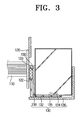
- Figure 3 is a cross-sectional view taken along line III-III of Figure 2;
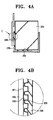
- Figure 4A is a cross-sectional view schematically showing a main part of an inkjet printer according to the present invention;
- Figure 4B shows part C of Figure 4A in detail;
- Figure 5 is an exploded perspective view schematically showing a main part of an array type inkjet printer in accordance with the present invention;
- Figure 6 is a cross-sectional view taken along line VI-VI of Figure 5; and
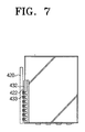
- Figure 7 is a cross-sectional view schematically showing an arrangement in which a main board and a head cable of an array type inkjet printer are directly contacted with each other.
-
- Throughout the drawings, the same drawing reference numerals will be understood to refer to the same elements, features, and structures.
- The matters defined in the description such as a detailed construction and elements are provided to assist in a comprehensive understanding of the embodiments of the invention. Also, descriptions of known functions and constructions are omitted for conciseness.
- Referring to FIGS. 2 and 3, the inkjet printer according to the present invention comprises a
printer body 100, atransfer shaft 101, afirst cable 110, adrive substrate 120 and anink cartridge unit 130. - The
printer body 100 is provided with various image forming parts. - Opposite ends of the
transfer shaft 101 are secured to theprinter body 100 to guide thecartridge unit 130 in the left and right direction. - The
first cable 110 is constituted of a flexible printed circuit (FPC) and is connected to a main board (not shown) installed within theprinter body 100. The other end of thefirst cable 110 is connected to thedrive substrate 120. In the present embodiment, although thefirst cable 110 is illustrated as being connected to the main board, thedrive substrate 120 may also serve as the main board in an array type inkjet printer. In that case, thefirst cable 110 would be directly connected to a host such as a computer. - The
drive substrate 120 is formed with a circuit pattern. A plurality ofcontact pads 122 within the circuit of thedrive substrate 120 are externally exposed on one side of thedrive substrate 120 allowing theink cartridge unit 130 to be connected to thedrive substrate 120. Thedrive substrate 120 extracts the printing data transmitted through thefirst cable 110 and amplifies the received printing data signals. - The
ink cartridge unit 130 comprises ahead cable 132, anink cartridge 134, anink cartridge carrier 136 and anelastic member 138. - The
head cable 132 is fixed to the bottom side of theink cartridge 134 allowing one end to be connected to thedrive substrate 120. The other end is connected to thehead chip 135 of theink cartridge 134.Head cable 132 may also be an FPC. In addition, a plurality offirst projections 133 which align with thecontact pads 122 are formed on the side of thehead cable 132 facing thedrive substrate 120. Thefirst projections 133 directly contact thecontact pads 122. Thus, thedrive substrate 120 and thehead cable 132 are connected to each other. - The
ink cartridge 134 stores ink. Ahead chip 135 is provided on the bottom side of theink cartridge 134 to eject ink in accordance with printing data transmitted through thehead cable 132 onto a printing medium to form an image. - The
ink cartridge carrier 136 houses theink cartridge 134. Theink cartridge 134 can be removed from theink cartridge carrier 136. In a shuttle type inkjet printer, theink cartridge carrier 136 moves theink cartridge 134 left and right along thetransfer shaft 101 when printing. - The
elastic member 138 is fixed to the rear side of theink cartridge 134 allowing thehead cable 132 to press against thedrive substrate 120. Theelastic member 138 is formed from elastic rubber. In addition, a plurality ofsecond projections 139 are formed on the side of theelastic member 132 facing thehead cable 132. The plurality ofsecond projections 139 align with thefirst projections 133, so that thecontact pads 122, thefirst projections 133 and the second projections 149 are all aligned. Thesecond projections 139 concentrate the pressure on thefirst projections 133 of thehead cable 132. Thus, thefirst projections 133 and thecontact pads 122 more effectively contact each other. Further, the first andsecond projections first projections 133 are more stable in their contact with thecontact pads 122. - Operation of the inkjet printer constructed as above will now be described in more detail.
- When a computer issues a request to print, printing data is transmitted to the
drive substrate 120 through thefirst cable 110. Thedrive substrate 120 extracts and amplifies the transmitted data. The data is transmitted to thehead cable 132 via thefirst projections 133 which contact with thecontact pads 122. The printing data is then transmitted to thehead chip 135 which ejects ink stored in theink cartridge 134 onto paper in accordance with the printing data. - The above-mentioned inkjet printer is not provided with the existing
second cable 30, as seen in Figure 1. Therefore, the number of parts is reduced. In addition, because the path which the printing data travels is shorter, the data is more reliably transmitted. Also, because theelastic member 138 is attached to anexchangeable ink cartridge 134, it is easy to repair the printer by exchanging theink cartridge unit 130 when theelastic member 138 becomes hardened. Thus, the life span of the printer is prolonged. - Referring to Figures 4A and 4B, elastic domes 233 (made of metal) are formed on the
head cable 232, instead of theelastic member 138. Theelastic domes 233 have an elasticity such that they to their original dome shape after an external force is removed, even if they are deformed by an external force. Preferably, theelastic domes 233 are similar to the metal terminals of a charger for a mobile telephone. However, theelastic domes 233 are not limited to steel domes and any member capable of forming contacts and having elasticity may be used. -
Elastic domes 233 are pressed into contact with thedrive substrate 220 when the ink cartridge 230 is mounted. Accordingly, thehead cable 232 may elastically contact thedrive substrate 220. Theelastic domes 233 are pressed into contact with thecontact pads 222 which are formed in thecircuit pattern 221 on thedrive substrate 220. This allows the printing data to communicate with thehead chip 235. The construction of such acircuit pattern 221 is known and thus description thereof is omitted. - The inkjet printer constructed as mentioned above is operated in the following manner.
- Printing data received by the
drive substrate 220 is transmitted to thehead chip 235 via theelastic domes 233 and thehead cable 232. The construction and functional action of this embodiment are the same as those of the embodiment of Figure 2 and so detailed description thereof is omitted. - As the inkjet printer constructed as mentioned above is not provided with a
second cable 30 and anelastic member - Referring to Figures 5 and 6, the array type inkjet printer is provided with a plurality of
head chips 335 for the colours yellow, magenta, cyan and black on the bottom of anink cartridge 334. In addition, ahead cable 332 is fixed to the bottom side of theink cartridge 334. Thus, thehead cable 332 is connected to the head chips 335. The other end of thehead cable 332 is provided with a plurality offirst projections 333. Thefirst projections 333 contact withcontact pads 322 provided on the side of acontact board 320, such as adrive substrate 320. Also, anelastic member 338 is interposed between thehead cable 332 and theink cartridge 334 One side of theelastic member 338 is provided with a plurality ofsecond projections 339 which are aligned with thefirst projections 333, thereby making thefirst projections 333 press into contact with thecontact pads 322. Thecontact board 320 is connected to amain board 302 by thefirst cable 310, and so themain board 302 receives printing data transmitted from a host. - Referring to Figure 7, a plurality of
contact pads 422 are formed on themain board 420. Thefirst projections 433 which are formed on thehead cable 432 contact thecontact pads 422. - As described above, the inventive contact arrangement of a head cable and a drive substrate may apply to an array type inkjet printer by changing the size of the head cable and the drive substrate and the number of the contact points. Although Figures 5 to 7 only show one example to which the embodiment of the present invention of Figure 3 is applied, the other embodiment of Figures 4A and 4B may be identically applied to such an array type inkjet printer.
- As described above, it is possible to save material costs because the number of parts are reduced by omitting a second cable and an elastic member which are needed in the prior art.
- In addition, because the path travelled by the printing data is reduced, it is possible to reduce the risk of losing printing data. Thus, the resultant product is enhanced in stability and reliability.
- Moreover, when the elastic member for compressing the head cable is hardened, it is possible to repair the printer in a simple manner by replacing the ink cartridge unit, which prolongs the life span of the printer.
Claims (25)
- An ink cartridge unit comprising:an ink cartridge having a head chip to eject ink stored in the ink cartridge according to printing data;a drive substrate having a circuit pattern; anda head cable connected to the drive substrate and capable of signal-communicating with the drive substrate; so that the printing data is receivable by the drive substrate, and transmittable to the head chip.
- An ink cartridge unit as claimed in claim 1, further comprisingan elastic member interposed between the head cable and the ink cartridge, so that the head cable is elastically compressed to contact the drive substrate.
- An ink cartridge unit as claimed in claim 2, wherein
the head cable is provided with a plurality of first projections on a side facing the drive substrate, and the elastic member is provided with a plurality of second projections corresponding to the first projections on a side facing the head cable. - An ink cartridge unit as claimed in claim 3, wherein
the elastic member is made of rubber material. - An ink cartridge unit as claimed in claim 1, wherein
the head cable is provided with a plurality of elastic domes on a side facing the drive substrate; so that the head cable elastically compresses and contacts the drive substrate; and
wherein the elastic domes are steel domes. - An inkjet printer comprising:a printer body;a drive substrate arranged on the printer body to receive printing data;an ink cartridge for storing ink with at least one head chip to eject ink stored in the ink cartridge onto a print medium according to the printing data; anda head cable connected with the drive substrate and capable of signal-communicating with the drive substrate, so that the printing data is receivable by the drive substrate, and transmittable to the at least one head chip.
- An inkjet printer as claimed in claim 6, further comprising
an elastic member interposed between the head cable and the ink cartridge, so that the head cable is elastically compressed and contacts the drive substrate. - An inkjet printer as claimed in claim 7, wherein
the head cable is provided with a plurality of first projections on a side facing the drive substrate, and the elastic member is provided with a plurality of second projections corresponding to the first projections on a side facing the head cable. - An inkjet printer as claimed in claim 8, wherein
the elastic member is made of rubber material. - An inkjet printer as claimed in claim 6, wherein
the head cable is provided with a plurality of elastic domes on a side facing the drive substrate; so that the head cable is elastically compressed and contacts with the drive substrate; and
wherein the elastic domes are steel domes. - An inkjet printer comprising:a printer body having a transfer shaft;an ink cartridge arranged to move along the transfer shaft, wherein the ink cartridge has a head chip to eject ink stored in the ink cartridge onto a print medium according to printing data;a drive substrate arranged on the printer body to receive the printing data; anda head cable connected with the drive substrate and capable of signal-communicating with the drive substrate, so that the printing data is receivable by the drive substrate, and transmittable to the head chip.
- An inkjet printer as claimed in claim 11, further comprising
an elastic member interposed between the head cable and the ink cartridge; so that the head cable is elastically compressed and contacts the drive substrate. - An inkjet printer as claimed in claim 12, wherein
the head cable is provided with a plurality of first projections on a side facing the drive substrate, and the elastic member is provided with a plurality of second projections corresponding to the first projections on a side facing the head cable; and
wherein the first and second projections are dome-shaped. - An inkjet printer as claimed in claim 11, wherein
the head cable is provided with a plurality of elastic domes on a side facing the drive substrate; so that the head cable is elastically compressed and contacts the drive substrate; and
wherein the elastic domes are steel domes. - An inkjet printer comprising:a printer body;an ink cartridge arranged on the printer body, wherein the ink cartridge has a plurality of head chips to eject ink stored in the ink cartridge onto a print medium according to printing data;a drive substrate arranged on the printer body to receive the printing data; anda head cable connected to the drive substrate and capable of signal-communicating with the drive substrate, so that the printing data is receivable by the drive substrate, and transmittable to the head chips.
- An inkjet printer as claimed in claim 15, further comprising
an elastic member interposed between the head cable and the ink cartridge, so that the head cable is elastically compressed and contacts the drive substrate. - An inkjet printer as claimed in claim 16, wherein
the head cable is provided with a plurality of first projections on a side facing the drive substrate, and the elastic member is provided with a plurality of second projections corresponding to the first projections on a side facing the head cable; and
wherein the first and second projections are dome-shaped. - An inkjet printer as claimed in claim 15, wherein
the head cable is provided with a plurality of elastic domes on a side facing the drive substrate; so that the head cable is elastically compressed and contacts the drive substrate; and
wherein the elastic domes are steel domes. - An inkjet printer as claimed in claim 15, further comprising:a main board being connected to a host to signal-communicate; anda first cable connecting the main board and the drive substrate to each other to signal-communicate.
- An inkjet printer as claimed in claim 15, wherein
the drive substrate is a main board connected to a host to signal-communicate. - An ink cartridge (134,234,334) for a printer comprising a print head (135,235,335) and a contact (132,232,332) for receiving print head control signals, the cartridge being characterised in that the contact (132,232,332) comprises a projecting contact element (139,239,339).
- An ink cartridge (134,234,334) according to claim 21, wherein said contact element (139,239,339) is comprised in an array of contact elements.
- An ink cartridge (134,234,334) for a printer comprising a print head (135,235,335) and a contact (132,232,332) for receiving print head control signals, the cartridge being characterised by means (133,233,333) for resiliently biasing the contact (132,232,332) in a given direction.
- A printer comprising an ink cartridge carriage, the printer being characterised in that the ink cartridge carriage has a contact pad (122,222,322) fixedly mounted therein.
- A printer according to claim 24, wherein the contact pad (122,222,322) is configured to correspond with the contact (132,232,332) of the ink cartridge (134,234,334) according to any one of claims 21, 22 or 23.
Applications Claiming Priority (4)
| Application Number | Priority Date | Filing Date | Title |
|---|---|---|---|
| KR20040009173 | 2004-02-12 | ||
| KR2004009173 | 2004-02-12 | ||
| KR1020040109161A KR100645434B1 (en) | 2004-02-12 | 2004-12-21 | Inkcatridge unit and inkjet printer having the same |
| KR2004109161 | 2004-12-21 |
Publications (1)
| Publication Number | Publication Date |
|---|---|
| EP1564004A1 true EP1564004A1 (en) | 2005-08-17 |
Family
ID=34703460
Family Applications (1)
| Application Number | Title | Priority Date | Filing Date |
|---|---|---|---|
| EP05100917A Withdrawn EP1564004A1 (en) | 2004-02-12 | 2005-02-09 | An Ink Cartridge |
Country Status (3)
| Country | Link |
|---|---|
| US (1) | US7284832B2 (en) |
| EP (1) | EP1564004A1 (en) |
| CN (1) | CN100425450C (en) |
Cited By (4)
| Publication number | Priority date | Publication date | Assignee | Title |
|---|---|---|---|---|
| WO2008088484A1 (en) * | 2006-12-21 | 2008-07-24 | Eastman Kodak Company | Data storage device mounting arrangement for printer |
| WO2010130219A1 (en) * | 2009-05-13 | 2010-11-18 | 珠海纳思达企业管理有限公司 | Adapter and ink cartridge provided on inkjet printer |
| WO2011144246A1 (en) * | 2010-05-20 | 2011-11-24 | Pelikan Hardcopy Production Ag | Printing material container and contact device |
| EP2431184A1 (en) * | 2009-05-13 | 2012-03-21 | Zhuhai Ninestar Management Co., Ltd. | Adapter on inkjet printer and ink cartridge used therewith |
Families Citing this family (8)
| Publication number | Priority date | Publication date | Assignee | Title |
|---|---|---|---|---|
| CN2905442Y (en) * | 2006-06-15 | 2007-05-30 | 珠海天威技术开发有限公司 | Ink-jet printer cartridge |
| JP5929168B2 (en) * | 2011-12-22 | 2016-06-01 | ブラザー工業株式会社 | Printing fluid cartridge |
| JP6950217B2 (en) * | 2017-03-22 | 2021-10-13 | セイコーエプソン株式会社 | Liquid discharge device |
| WO2018222194A1 (en) * | 2017-06-01 | 2018-12-06 | Hewlett-Packard Development Company, L.P. | Printhead carriages with mechanical protectors |
| CN109605940B (en) * | 2018-12-12 | 2024-03-22 | 中山市毕升打印科技有限公司 | Welding-free ink box printing equipment |
| CN110027324A (en) | 2019-05-06 | 2019-07-19 | 珠海艾派克微电子有限公司 | Nozzle print cartridge, inkjet component and circuit substrate |
| CN110202943B (en) * | 2019-07-08 | 2020-05-05 | 珠海艾派克微电子有限公司 | Ink box |
| CN111243074B (en) * | 2020-01-08 | 2020-10-27 | 广东新中望信息科技有限公司 | Three-dimensional simulation method, system and storage medium integrating 5G, IPV6 |
Citations (5)
| Publication number | Priority date | Publication date | Assignee | Title |
|---|---|---|---|---|
| EP0547596A2 (en) * | 1991-12-19 | 1993-06-23 | Canon Kabushiki Kaisha | Ink jet recording head, ink jet recording head cartridge and recording apparatus using same |
| EP0622233A2 (en) * | 1993-04-30 | 1994-11-02 | Hewlett-Packard Company | Electrical interconnect system for a printer |
| US5835111A (en) * | 1995-10-31 | 1998-11-10 | Hewlett-Packard Company | Compact flex-circuit interconnect for inkjet printheads |
| US5971525A (en) * | 1993-09-08 | 1999-10-26 | Canon Kabushiki Kaisha | Recording apparatus having a deelectrifying member for a recording head |
| EP1199169A1 (en) * | 1999-06-30 | 2002-04-24 | Copyer Co., Ltd. | Ink-jet image forming device |
Family Cites Families (10)
| Publication number | Priority date | Publication date | Assignee | Title |
|---|---|---|---|---|
| US4706097A (en) * | 1986-04-03 | 1987-11-10 | Hewlett Packard Company | Near-linear spring connect structure for flexible interconnect circuits |
| US4907018A (en) * | 1988-11-21 | 1990-03-06 | Hewlett-Packard Company | Printhead-carriage alignment and electrical interconnect lock-in mechanism |
| AU3241795A (en) | 1994-08-09 | 1996-03-07 | Encad, Inc. | Printer ink cartridge |
| KR100186587B1 (en) | 1996-05-21 | 1999-05-15 | 김광호 | Apparatus for transferring data to the carrier of inkjet printer |
| KR100224926B1 (en) | 1997-03-06 | 1999-10-15 | 윤종용 | Head for inkjet printer |
| JP3655452B2 (en) * | 1997-12-25 | 2005-06-02 | 株式会社東芝 | HEAD SUSPENSION ASSEMBLY, MAGNETIC DISK DEVICE EQUIPPED WITH THE SAME, AND METHOD FOR CONNECTING RELAY PRINTED CIRCUIT BOARD |
| US6796635B2 (en) | 2000-10-11 | 2004-09-28 | Seiko Epson Corporation | Ink cartridge and inkjet printer |
| KR100385987B1 (en) * | 2001-01-22 | 2003-06-02 | 삼성전자주식회사 | Apparatus for electrical contact of inkjet printer |
| US6431684B1 (en) * | 2001-08-01 | 2002-08-13 | Hewlett-Packard Company | Spring pad for electrical interconnection of inkjet printing system |
| US6536872B2 (en) * | 2001-08-16 | 2003-03-25 | Lexmark International, Inc. | Connection module |
-
2005
- 2005-02-04 US US11/049,994 patent/US7284832B2/en not_active Expired - Fee Related
- 2005-02-08 CN CNB2005100516209A patent/CN100425450C/en not_active Expired - Fee Related
- 2005-02-09 EP EP05100917A patent/EP1564004A1/en not_active Withdrawn
Patent Citations (5)
| Publication number | Priority date | Publication date | Assignee | Title |
|---|---|---|---|---|
| EP0547596A2 (en) * | 1991-12-19 | 1993-06-23 | Canon Kabushiki Kaisha | Ink jet recording head, ink jet recording head cartridge and recording apparatus using same |
| EP0622233A2 (en) * | 1993-04-30 | 1994-11-02 | Hewlett-Packard Company | Electrical interconnect system for a printer |
| US5971525A (en) * | 1993-09-08 | 1999-10-26 | Canon Kabushiki Kaisha | Recording apparatus having a deelectrifying member for a recording head |
| US5835111A (en) * | 1995-10-31 | 1998-11-10 | Hewlett-Packard Company | Compact flex-circuit interconnect for inkjet printheads |
| EP1199169A1 (en) * | 1999-06-30 | 2002-04-24 | Copyer Co., Ltd. | Ink-jet image forming device |
Cited By (7)
| Publication number | Priority date | Publication date | Assignee | Title |
|---|---|---|---|---|
| WO2008088484A1 (en) * | 2006-12-21 | 2008-07-24 | Eastman Kodak Company | Data storage device mounting arrangement for printer |
| US7731335B2 (en) | 2006-12-21 | 2010-06-08 | Eastman Kodak Company | Data storage device mounting arrangement for printing device |
| WO2010130219A1 (en) * | 2009-05-13 | 2010-11-18 | 珠海纳思达企业管理有限公司 | Adapter and ink cartridge provided on inkjet printer |
| EP2431184A1 (en) * | 2009-05-13 | 2012-03-21 | Zhuhai Ninestar Management Co., Ltd. | Adapter on inkjet printer and ink cartridge used therewith |
| EP2431184A4 (en) * | 2009-05-13 | 2012-10-31 | Zhuhai Ninestar Man Co Ltd | Adapter on inkjet printer and ink cartridge used therewith |
| US8591006B2 (en) | 2009-05-13 | 2013-11-26 | Zhuhai Ninestar Management Co., Ltd. | Adapter and an ink cartridge mounted on an ink-jet printer |
| WO2011144246A1 (en) * | 2010-05-20 | 2011-11-24 | Pelikan Hardcopy Production Ag | Printing material container and contact device |
Also Published As
| Publication number | Publication date |
|---|---|
| US7284832B2 (en) | 2007-10-23 |
| CN1654216A (en) | 2005-08-17 |
| US20050179753A1 (en) | 2005-08-18 |
| CN100425450C (en) | 2008-10-15 |
Similar Documents
| Publication | Publication Date | Title |
|---|---|---|
| EP1564004A1 (en) | An Ink Cartridge | |
| EP0581298B1 (en) | Ink jet recording head, ink jet recording head cartridge, recording apparatus using the same and method of manufacturing the head | |
| MX2007001386A (en) | Printing material housing device. | |
| US7290854B2 (en) | Ink jet recording method and ink jet recording apparatus | |
| EP1281535B1 (en) | Spring pad for electrical interconnection of inkjet printing system | |
| US7954937B2 (en) | Ink jet printing apparatus | |
| KR100385987B1 (en) | Apparatus for electrical contact of inkjet printer | |
| US6733317B2 (en) | Recording apparatus | |
| JPH08244245A (en) | Printer | |
| KR100645434B1 (en) | Inkcatridge unit and inkjet printer having the same | |
| US20030035026A1 (en) | Connection module | |
| KR970001596B1 (en) | Ink-jet recording head, inkjet recording head cartridge and recording apparatus using the same | |
| EP0650847A2 (en) | A recording apparatus with an ink tank and an information processing equipment having said recording apparatus | |
| JP2004358912A (en) | Head cartridge | |
| JP4737430B2 (en) | Carriage device, recording device, liquid ejecting device | |
| KR100492088B1 (en) | Printing apparatus and electronic device having a line contact structure | |
| EP1661709B1 (en) | Printer | |
| JP4106538B2 (en) | Recording device | |
| US8525859B2 (en) | Thermal head and thermal printer | |
| JP4713389B2 (en) | Inkjet printer | |
| JP2002283544A (en) | Printer | |
| KR100186587B1 (en) | Apparatus for transferring data to the carrier of inkjet printer | |
| JP2004017419A (en) | Noncontact cartridge information transmitter and recorder comprising the same | |
| EP0933224A3 (en) | Ink jet recording head and ink jet recording apparatus | |
| JP2000225693A (en) | Printing device and ink cartridge |
Legal Events
| Date | Code | Title | Description |
|---|---|---|---|
| PUAI | Public reference made under article 153(3) epc to a published international application that has entered the european phase |
Free format text: ORIGINAL CODE: 0009012 |
|
| AK | Designated contracting states |
Kind code of ref document: A1 Designated state(s): AT BE BG CH CY CZ DE DK EE ES FI FR GB GR HU IE IS IT LI LT LU MC NL PL PT RO SE SI SK TR |
|
| AX | Request for extension of the european patent |
Extension state: AL BA HR LV MK YU |
|
| 17P | Request for examination filed |
Effective date: 20050903 |
|
| AKX | Designation fees paid |
Designated state(s): DE FR GB NL |
|
| 17Q | First examination report despatched |
Effective date: 20090217 |
|
| STAA | Information on the status of an ep patent application or granted ep patent |
Free format text: STATUS: THE APPLICATION IS DEEMED TO BE WITHDRAWN |
|
| 18D | Application deemed to be withdrawn |
Effective date: 20090630 |