EP1559558A2 - Replaceable memory device for a consumable substance container - Google Patents
Replaceable memory device for a consumable substance container Download PDFInfo
- Publication number
- EP1559558A2 EP1559558A2 EP05000587A EP05000587A EP1559558A2 EP 1559558 A2 EP1559558 A2 EP 1559558A2 EP 05000587 A EP05000587 A EP 05000587A EP 05000587 A EP05000587 A EP 05000587A EP 1559558 A2 EP1559558 A2 EP 1559558A2
- Authority
- EP
- European Patent Office
- Prior art keywords
- memory device
- container
- consumable substance
- consumable
- replaceable
- Prior art date
- Legal status (The legal status is an assumption and is not a legal conclusion. Google has not performed a legal analysis and makes no representation as to the accuracy of the status listed.)
- Withdrawn
Links
Images


Classifications
-
- B—PERFORMING OPERATIONS; TRANSPORTING
- B41—PRINTING; LINING MACHINES; TYPEWRITERS; STAMPS
- B41J—TYPEWRITERS; SELECTIVE PRINTING MECHANISMS, i.e. MECHANISMS PRINTING OTHERWISE THAN FROM A FORME; CORRECTION OF TYPOGRAPHICAL ERRORS
- B41J2/00—Typewriters or selective printing mechanisms characterised by the printing or marking process for which they are designed
- B41J2/005—Typewriters or selective printing mechanisms characterised by the printing or marking process for which they are designed characterised by bringing liquid or particles selectively into contact with a printing material
- B41J2/01—Ink jet
- B41J2/17—Ink jet characterised by ink handling
- B41J2/175—Ink supply systems ; Circuit parts therefor
- B41J2/17503—Ink cartridges
- B41J2/1752—Mounting within the printer
-
- A—HUMAN NECESSITIES
- A01—AGRICULTURE; FORESTRY; ANIMAL HUSBANDRY; HUNTING; TRAPPING; FISHING
- A01G—HORTICULTURE; CULTIVATION OF VEGETABLES, FLOWERS, RICE, FRUIT, VINES, HOPS OR SEAWEED; FORESTRY; WATERING
- A01G31/00—Soilless cultivation, e.g. hydroponics
- A01G31/02—Special apparatus therefor
-
- A—HUMAN NECESSITIES
- A01—AGRICULTURE; FORESTRY; ANIMAL HUSBANDRY; HUNTING; TRAPPING; FISHING
- A01G—HORTICULTURE; CULTIVATION OF VEGETABLES, FLOWERS, RICE, FRUIT, VINES, HOPS OR SEAWEED; FORESTRY; WATERING
- A01G9/00—Cultivation in receptacles, forcing-frames or greenhouses; Edging for beds, lawn or the like
-
- B—PERFORMING OPERATIONS; TRANSPORTING
- B41—PRINTING; LINING MACHINES; TYPEWRITERS; STAMPS
- B41J—TYPEWRITERS; SELECTIVE PRINTING MECHANISMS, i.e. MECHANISMS PRINTING OTHERWISE THAN FROM A FORME; CORRECTION OF TYPOGRAPHICAL ERRORS
- B41J2/00—Typewriters or selective printing mechanisms characterised by the printing or marking process for which they are designed
- B41J2/005—Typewriters or selective printing mechanisms characterised by the printing or marking process for which they are designed characterised by bringing liquid or particles selectively into contact with a printing material
- B41J2/01—Ink jet
- B41J2/17—Ink jet characterised by ink handling
- B41J2/175—Ink supply systems ; Circuit parts therefor
- B41J2/17503—Ink cartridges
- B41J2/17513—Inner structure
-
- B—PERFORMING OPERATIONS; TRANSPORTING
- B41—PRINTING; LINING MACHINES; TYPEWRITERS; STAMPS
- B41J—TYPEWRITERS; SELECTIVE PRINTING MECHANISMS, i.e. MECHANISMS PRINTING OTHERWISE THAN FROM A FORME; CORRECTION OF TYPOGRAPHICAL ERRORS
- B41J2/00—Typewriters or selective printing mechanisms characterised by the printing or marking process for which they are designed
- B41J2/005—Typewriters or selective printing mechanisms characterised by the printing or marking process for which they are designed characterised by bringing liquid or particles selectively into contact with a printing material
- B41J2/01—Ink jet
- B41J2/17—Ink jet characterised by ink handling
- B41J2/175—Ink supply systems ; Circuit parts therefor
- B41J2/17503—Ink cartridges
- B41J2/17543—Cartridge presence detection or type identification
- B41J2/17546—Cartridge presence detection or type identification electronically
-
- B—PERFORMING OPERATIONS; TRANSPORTING
- B41—PRINTING; LINING MACHINES; TYPEWRITERS; STAMPS
- B41J—TYPEWRITERS; SELECTIVE PRINTING MECHANISMS, i.e. MECHANISMS PRINTING OTHERWISE THAN FROM A FORME; CORRECTION OF TYPOGRAPHICAL ERRORS
- B41J29/00—Details of, or accessories for, typewriters or selective printing mechanisms not otherwise provided for
- B41J29/38—Drives, motors, controls or automatic cut-off devices for the entire printing mechanism
- B41J29/393—Devices for controlling or analysing the entire machine ; Controlling or analysing mechanical parameters involving printing of test patterns
-
- Y—GENERAL TAGGING OF NEW TECHNOLOGICAL DEVELOPMENTS; GENERAL TAGGING OF CROSS-SECTIONAL TECHNOLOGIES SPANNING OVER SEVERAL SECTIONS OF THE IPC; TECHNICAL SUBJECTS COVERED BY FORMER USPC CROSS-REFERENCE ART COLLECTIONS [XRACs] AND DIGESTS
- Y02—TECHNOLOGIES OR APPLICATIONS FOR MITIGATION OR ADAPTATION AGAINST CLIMATE CHANGE
- Y02P—CLIMATE CHANGE MITIGATION TECHNOLOGIES IN THE PRODUCTION OR PROCESSING OF GOODS
- Y02P60/00—Technologies relating to agriculture, livestock or agroalimentary industries
- Y02P60/20—Reduction of greenhouse gas [GHG] emissions in agriculture, e.g. CO2
- Y02P60/21—Dinitrogen oxide [N2O], e.g. using aquaponics, hydroponics or efficiency measures
Definitions
- This invention relates generally to containers for consumable substances, and more particularly to replaceable containers having integral electronic memory devices.
- the substance may be needed for the equipment to operate properly, such as a fuel or lubricant; or the substance may be utilized by the equipment as a component or ingredient in forming a final product or output.
- Consumable substances may be provided in replaceable containers that are changed when the substance is depleted.
- printers with user-replaceable consumables are well known in the art.
- inkjet printers typically utilize replaceable ink supplies, either integrated with a printhead or in the form of separate supplies.
- toner is typically supplied in a replaceable cartridge, which may include the photosensitive drum on which images are formed.
- the memory device may be used as a "keying" feature to differentiate between different substances, may contain calibration information, or may be used to indicate a status condition of the consumable, such as the substance level within the consumable.
- the memory devices may also be used for many other purposes, such as enabling specialized features of the device or providing other value to the equipment user. While earlier memory devices typically had electrical contacts that had to connect to mating contacts in the utilizing equipment, newer devices are often wireless and rely on radio frequency (RF) communication.
- RF radio frequency
- a memory device When a memory device is used to differentiate between substantially similar containers having different contents (such as ink supplies containing different ink colors or having different fill levels), it is typically preferable that the differentiation take place as far down the assembly line as possible, such that fewer distinct lines of components need to be dealt with, and greater flexibility exists in the supply chain and manufacturing process.
- a simple method of replacing the integral memory device may prove more cost effective than electrically reprogramming the memory device. If an integral memory device on a container has failed, a simple method of replacement can also allow for cost-effective repair of a consumable container.
- Embodiments of the present invention include wireless electronic memory devices formed within plugs or "corking members" for sealing the filling ports of containers of consumable substances; containers incorporating the plugs; and related methods.
- Fig. 1 illustrates an exemplary printer consumable in which embodiments of the invention may be used
- Figures 2(a) and 2(b) are partial cross-sectional views taken along line 2-2 of FIG. 1, illustrating the fill port region of the exemplary consumable during and after the insertion of a corking member;
- Fig. 3 is a partial cutaway view of an exemplary corking member according to an embodiment of the invention.
- Fig. 4 is an electrical block diagram illustrating the operation of an exemplary memory device
- Fig. 5 illustrates an exemplary printing system in which embodiments of the present invention may be used
- Fig. 6 illustrates in schematic form how an antenna mounted within the exemplary printer is located in close proximity to the memory device, and is aligned with the antenna of the memory device;
- Figs. 7(a) and 7(b) illustrate one approach that may be utilized to physically insure that the exemplary corking member maintains a correct alignment when placed in the fill port;
- Figs. 8(a) and 8(b) illustrate another approach that may be utilized to physically insure that the exemplary corking member maintains a correct alignment when placed in the fill port;
- Figs. 9(a), 9(b), 9(c), and 9(d) illustrate how one corking member 200''' previously placed in a fill port 120 may be replaced with a new corking member 700' according to an embodiment of the invention.
- Fig. 10 illustrates an alternative exemplary corking member, according to a further embodiment of the invention.
- Embodiments of the invention are described with respect to an exemplary inkjet printing consumable; however, the invention is not limited to the exemplary consumable nor to the field of inkjet consumables, but may be utilized in other consumable substance containers having fill ports.
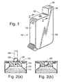
- Fig. 1 illustrates an exemplary printer consumable 100 in which embodiments of the invention may be used.
- the exemplary consumable is of the type that is typically installed on the printing carriage of a printer and which includes an integral printhead, but other types of printing consumables may also utilize the invention, such as, for example, ink containers without printheads that are mounted either on the scanning carriage or remotely located ("off-axis").
- the exemplary consumable is shown oriented with the fill port 120 facing up, as the consumable would be oriented during the ink-fill operation.
- the illustrated consumable is formed of a rigid outer frame 102 onto which metal side pieces 104 are pressed; the consumable has a "snout" region 106 that includes a printhead 108.
- a circular fill port 120 is provided through the frame 102, allowing the consumable to be filled with liquid ink.
- Embodiments of the exemplary consumable 100 may have a more complex structure, such as, for example, the frame for an ink-jet cartridge described in US 5,737,002 (Swanson et al., TWO MATERIAL FRAME HAVING DISSIMILAR PROPERTIES FOR THERMAL INK-JET CARTRIDGE).
- Embodiments of the exemplary consumable may also include additional mechanisms, such as mechanisms for regulating backpressure during printing (not shown in Fig. 1).
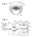
- FIGS. 2(a) and 2(b) are partial cross-sectional views taken along line 2--2 of FIG. 1, illustrating the fill port 120 region of the exemplary consumable.
- the consumable is held with the snout region 106 in an upright position as shown in FIG. 1.
- a needle (not illustrated) is lowered through the fill port opening 120 down into the ink reservoir 112 nearly touching the bottom of the reservoir. This is done so that the ink falls the shortest distance possible, as some inks will foam if they fall, which makes priming of the printhead difficult.
- the pen reservoir 112 is then filled with ink through the ink fill needle by a pump to the point that the ink in the reservoir is nearly touching the inside of the ink fill hole 120.
- the corking member includes an electronic memory device as discussed below, and may have other forms than a substantially round ball, as also discussed below.
- both the fill port 120 and corking member 200 have substantially round cross-sections, although other configurations are possible.
- the corking member fits tightly within the opening 120, and displaces some of the plastic material surrounding the opening 120 as it is inserted, due to its size relative to the opening size.
- the corking member 120 is pressed into the ink fill 120 by a pressing tool 300 such that it tightly seals the ink fill port.
- the final position of the corking member 200 within the fill port is shown in Fig. 2(b).
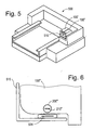
- Fig. 3 is a partial cutaway view of a corking member 200' according to an embodiment of the invention. As indicated by the dashed line, the upper portion of the body of the corking member is shown in phantom such that the interior is visible. Inside the body of the corking member is an electronic memory device 210 that incorporates radio frequency communication capabilities utilizing technology sometimes referred to as Radio Frequency Identification (RFID).
- RFID Radio Frequency Identification
- the exemplary memory device includes an antenna coil 214 mounted on a 2.5mm square integrated circuit chip; the antenna surrounds electronic circuitry 212 providing power generation, control circuitry, and memory, as described below. With the antenna coil formed on the chip surface, the exemplary electronic memory device 210 may be embedded into the corking member 200' without the need for any additional electronic circuitry or external electrical connections.
- Other suitable technologies may also be used, including technologies in which the electronic circuitry and antenna are mounted on a common substrate, and technologies utilizing a discrete antenna element.
- the exemplary memory device 210 is a Read/Write device with 128 byte total memory which can be written to or read using various RFID reader methods known in the art.
- a reader/writer (not shown in Fig. 3) is placed adjacent to the item containing the memory device; the memory device derives both electrical power and data from the RF field generated by the reader/writer.
- the exemplary memory device operates with a carrier frequency of 13.56 MHz; an operating distance of approximately 0.5mm to 3mm (variable depending on the performance of the Reader/Writer or system environment); and a data rate of 26.48 thousand bits-per-second (kbps).
- the memory of the exemplary device is configured as Electrically Erasable Programmable Read-Only-Memory (EEPROM), although other configurations of memory may be utilized, such as, for example, Read-Only-Memory (ROM) or Programmable Read-Only-Memory (PROM).
- EEPROM Electrically Erasable Programmable Read-Only-Memory
- ROM Read-Only-Memory
- PROM Programmable Read-Only-Memory
- Corking member 200' may be produced by molding a suitable material 216 around the memory device 210, or by any of the various packaging methods known in the art.
- Fig. 4 is an electrical block diagram illustrating the operation of the exemplary memory device.
- Contained on the integrated circuit 310 are a coil antenna 314 and the electronic circuitry 312.
- the electronic circuitry includes a power generation circuit 410 to derive electrical power for the electronic circuitry from the RF field impinging on the antenna; EEPROM 414; and control circuitry 412 to control reading and writing from the EEPROM 414 and to receive data from, and send data to, the antenna.
- control electronics 420 in the device in which the consumable is installed (or in a separate programming or reading station) generate signals to control a transceiver 422 attached to an antenna 424, which generates an RF field that allows reading and writing of data from the memory device 310.
- Fig. 5 illustrates an exemplary printing system 500 in which embodiments of the present invention may be used.
- the invention may also be utilized in printers having different configurations, and with devices other than printers that utilize containers of consumable substances.
- one or more containers 100', 100" may typically be installed in a scanning carriage 510 of the exemplary printer; the carriage is scanned across print media as ink or other fluids are deposited on the media.
- Fig. 6 illustrates in schematic form how an antenna coil 524 mounted on the scanning carriage of the exemplary printer is located in close proximity to the memory device 210" contained within the corking member 200" (for clarity, the consumable container 100" and corking member 200" are not shown to scale).
- antenna coil 524 is connected to a transceiver (not shown in Fig. 6) located within the printer.
- the antenna of the memory device 210" is maintained in a proper alignment with the antenna on the scanning carriage, with the coil antennas substantially parallel, since communication is degraded if the antenna coils are not properly aligned.
- antenna coil 524 is mounted in any appropriate location providing close proximity and proper alignment to the consumable fill port.
- Figs. 7(a) and 7(b) illustrate one approach that may be utilized to physically insure that the exemplary corking member 700 maintains a correct alignment when placed in the fill port 120.
- the leading portion 704 of the corking member is elongated, insuring that the corking member is correctly aligned for installation into the fill port, and does not rotate out of alignment as it is inserted.
- the cross-section of the exemplary corking member 700 is typically round, as discussed above.
- the trailing portion 702 of the corking member may be substantially the same as shown in previous figures.
- Figs. 8(a) and 8(b) illustrate how "fins" or protuberances 804 may be provided on the trailing portion of the corking member 800, with the leading portion 802 substantially the same as shown in Figs. 2, 3, and 6.
- the fins 804 also ensure that the corking member maintains a correct alignment with the fill port 120.
- Combinations of the leading and trailing features as shown in Figs. 7 and 8 may also be utilized; or any other physical alignment feature that ensures the correct alignment of the corking member with the fill port.
- the fill port may be configured help correctly align the corking member, such as by shaping the sides of the fill port to facilitate alignment (not shown).
- Embodiments of the corking member may lack physical alignment features, such as the ball-shaped members shown in Figs. 2(a), 2(b), and 3, provided that the insertion process for the corking member into the fill port reliably provides for proper alignment.
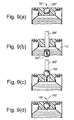
- Figs. 9(a), 9(b), 9(c), and 9(d) illustrate how one corking member 200''' previously placed in a fill port 120 may be replaced with a new corking member 700' according to an embodiment of the invention.
- Replacement may be effectuated to replace a defective memory device with a properly operating device, to upgrade or change the contents of the memory device by physically replacing it, or to provide a memory device on a container that previously lacked a memory device.
- FIG. 9(a) previously installed corking member 200" is in fill port 120.
- pressing tool 300' pushes the previously installed corking member out of the fill port and into the fluid reservoir 112.
- previously installed corking member 200" includes a functioning memory device, the corking member 200" will now be too distant from a read/write antenna placed adjacent to the fill port to be accessed.
- pressing too 300" is utilized to press new or replacement corking member 700' into the fill port;
- Fig. 9(d) new or replacement corking member 700' is seen installed in the fill port.
- Some types of containers for consumable substances have a fill port that is sealed in some other fashion than the insertion of a corking member, such as, for example, the placement of a sealing tape or label over the fill port.
- a memory device according to the present invention may be added to these containers by removing the sealing tape or label, if necessary, and pressing a corking member into the fill port as depicted in Figs. 9(c) and 9(d).
- Fig. 10 illustrates an alternative embodiment of a corking member, in which a memory device 210''' is externally attached to a corking member 1000.
- the memory device may be adhered to the corking member and encapsulated by a material 1020 such as epoxy.
- the memory device may be packaged according to any of the packaging methods known in the art, with the package then adhered to the corking member (not shown).
Abstract
Description
- This invention relates generally to containers for consumable substances, and more particularly to replaceable containers having integral electronic memory devices.
- Many types of equipment or devices require a supply of a consumable substance. The substance may be needed for the equipment to operate properly, such as a fuel or lubricant; or the substance may be utilized by the equipment as a component or ingredient in forming a final product or output. Consumable substances may be provided in replaceable containers that are changed when the substance is depleted.
- Printers with user-replaceable consumables (and related devices, such as facsimile machines and copiers) are well known in the art. For example, inkjet printers typically utilize replaceable ink supplies, either integrated with a printhead or in the form of separate supplies. In laser printers, toner is typically supplied in a replaceable cartridge, which may include the photosensitive drum on which images are formed.
- In manufacturing containers of consumable substances, it is typical to fill the containers at a much more rapid rate than the rate at which the substance is subsequently withdrawn from the container by the utilizing equipment. With ink supplies for printers, for example, one common technique for rapidly filling consumables with ink is to provide a separate filling port on the consumable, sized to accept an ink-fill needle. Ink is then rapidly injected into the container on an assembly line. After the consumable is filled and the needle withdrawn, the filling port is closed, typically with a plug.
- It is increasingly common for containers of consumable substances to have integral electronic memory devices, which may be used for a variety of purposes by the utilizing equipment. The memory device may be used as a "keying" feature to differentiate between different substances, may contain calibration information, or may be used to indicate a status condition of the consumable, such as the substance level within the consumable. The memory devices may also be used for many other purposes, such as enabling specialized features of the device or providing other value to the equipment user. While earlier memory devices typically had electrical contacts that had to connect to mating contacts in the utilizing equipment, newer devices are often wireless and rely on radio frequency (RF) communication.
- Changes to the physical design of a replaceable container can be prohibitively expensive, both in terms of research and development expense and in the costs of retooling an assembly line. While adding a memory device to an existing line of containers may be desirable, there is also generally a need to maintain backward compatibility to older equipment.
- When a memory device is used to differentiate between substantially similar containers having different contents (such as ink supplies containing different ink colors or having different fill levels), it is typically preferable that the differentiation take place as far down the assembly line as possible, such that fewer distinct lines of components need to be dealt with, and greater flexibility exists in the supply chain and manufacturing process.
- Further, if a need arises to re-characterize a container after manufacturer (such as, for example, to provide updated information about the consumable substance or to enable new or revised features of the equipment), a simple method of replacing the integral memory device may prove more cost effective than electrically reprogramming the memory device. If an integral memory device on a container has failed, a simple method of replacement can also allow for cost-effective repair of a consumable container.
- Embodiments of the present invention include wireless electronic memory devices formed within plugs or "corking members" for sealing the filling ports of containers of consumable substances; containers incorporating the plugs; and related methods.
- Other aspects and advantages of the present invention will become apparent from the following detailed description, taken in conjunction with the accompanying drawings, illustrating by way of example the principles of the invention.
- Fig. 1 illustrates an exemplary printer consumable in which embodiments of the invention may be used;
- Figures 2(a) and 2(b) are partial cross-sectional views taken along line 2-2 of FIG. 1, illustrating the fill port region of the exemplary consumable during and after the insertion of a corking member;
- Fig. 3 is a partial cutaway view of an exemplary corking member according to an embodiment of the invention;
- Fig. 4 is an electrical block diagram illustrating the operation of an exemplary memory device;
- Fig. 5 illustrates an exemplary printing system in which embodiments of the present invention may be used;
- Fig. 6 illustrates in schematic form how an antenna mounted within the exemplary printer is located in close proximity to the memory device, and is aligned with the antenna of the memory device;
- Figs. 7(a) and 7(b) illustrate one approach that may be utilized to physically insure that the exemplary corking member maintains a correct alignment when placed in the fill port;
- Figs. 8(a) and 8(b) illustrate another approach that may be utilized to physically insure that the exemplary corking member maintains a correct alignment when placed in the fill port;
- Figs. 9(a), 9(b), 9(c), and 9(d) illustrate how one corking member 200''' previously placed in a
fill port 120 may be replaced with a new corking member 700' according to an embodiment of the invention; and - Fig. 10 illustrates an alternative exemplary corking member, according to a further embodiment of the invention.
- Embodiments of the invention are described with respect to an exemplary inkjet printing consumable; however, the invention is not limited to the exemplary consumable nor to the field of inkjet consumables, but may be utilized in other consumable substance containers having fill ports.
- Fig. 1 illustrates an exemplary printer consumable 100 in which embodiments of the invention may be used. The exemplary consumable is of the type that is typically installed on the printing carriage of a printer and which includes an integral printhead, but other types of printing consumables may also utilize the invention, such as, for example, ink containers without printheads that are mounted either on the scanning carriage or remotely located ("off-axis").
- The exemplary consumable is shown oriented with the
fill port 120 facing up, as the consumable would be oriented during the ink-fill operation. The illustrated consumable is formed of a rigidouter frame 102 onto whichmetal side pieces 104 are pressed; the consumable has a "snout"region 106 that includes aprinthead 108. Acircular fill port 120 is provided through theframe 102, allowing the consumable to be filled with liquid ink. - For clarity the exemplary consumable 100 is shown in somewhat simplified form. Embodiments of the exemplary consumable may have a more complex structure, such as, for example, the frame for an ink-jet cartridge described in US 5,737,002 (Swanson et al., TWO MATERIAL FRAME HAVING DISSIMILAR PROPERTIES FOR THERMAL INK-JET CARTRIDGE). Embodiments of the exemplary consumable may also include additional mechanisms, such as mechanisms for regulating backpressure during printing (not shown in Fig. 1).
- Figures 2(a) and 2(b) are partial cross-sectional views taken along
line 2--2 of FIG. 1, illustrating thefill port 120 region of the exemplary consumable. To fill theink reservoir 112 of the exemplary consumable, the consumable is held with thesnout region 106 in an upright position as shown in FIG. 1. A needle (not illustrated) is lowered through the fill port opening 120 down into theink reservoir 112 nearly touching the bottom of the reservoir. This is done so that the ink falls the shortest distance possible, as some inks will foam if they fall, which makes priming of the printhead difficult. Thepen reservoir 112 is then filled with ink through the ink fill needle by a pump to the point that the ink in the reservoir is nearly touching the inside of theink fill hole 120. At this point the needle is drawn out of the consumable and acorking member 200 is placed over theink fill port 120, as shown in Fig. 2(a). The corking member includes an electronic memory device as discussed below, and may have other forms than a substantially round ball, as also discussed below. Typically both thefill port 120 andcorking member 200 have substantially round cross-sections, although other configurations are possible. The corking member fits tightly within theopening 120, and displaces some of the plastic material surrounding theopening 120 as it is inserted, due to its size relative to the opening size. Thecorking member 120 is pressed into theink fill 120 by apressing tool 300 such that it tightly seals the ink fill port. The final position of thecorking member 200 within the fill port is shown in Fig. 2(b). - Fig. 3 is a partial cutaway view of a corking member 200' according to an embodiment of the invention. As indicated by the dashed line, the upper portion of the body of the corking member is shown in phantom such that the interior is visible. Inside the body of the corking member is an
electronic memory device 210 that incorporates radio frequency communication capabilities utilizing technology sometimes referred to as Radio Frequency Identification (RFID). - One exemplary suitable technology for implementing the memory device is Coil-on-ChipTM technology developed by Hitachi Maxell. The exemplary memory device includes an
antenna coil 214 mounted on a 2.5mm square integrated circuit chip; the antenna surroundselectronic circuitry 212 providing power generation, control circuitry, and memory, as described below. With the antenna coil formed on the chip surface, the exemplaryelectronic memory device 210 may be embedded into the corking member 200' without the need for any additional electronic circuitry or external electrical connections. Other suitable technologies may also be used, including technologies in which the electronic circuitry and antenna are mounted on a common substrate, and technologies utilizing a discrete antenna element. - The
exemplary memory device 210 is a Read/Write device with 128 byte total memory which can be written to or read using various RFID reader methods known in the art. Typically, a reader/writer (not shown in Fig. 3) is placed adjacent to the item containing the memory device; the memory device derives both electrical power and data from the RF field generated by the reader/writer. The exemplary memory device operates with a carrier frequency of 13.56 MHz; an operating distance of approximately 0.5mm to 3mm (variable depending on the performance of the Reader/Writer or system environment); and a data rate of 26.48 thousand bits-per-second (kbps). The memory of the exemplary device is configured as Electrically Erasable Programmable Read-Only-Memory (EEPROM), although other configurations of memory may be utilized, such as, for example, Read-Only-Memory (ROM) or Programmable Read-Only-Memory (PROM). - Corking member 200' may be produced by molding a
suitable material 216 around thememory device 210, or by any of the various packaging methods known in the art. - Fig. 4 is an electrical block diagram illustrating the operation of the exemplary memory device. Contained on the
integrated circuit 310 are acoil antenna 314 and theelectronic circuitry 312. The electronic circuitry includes apower generation circuit 410 to derive electrical power for the electronic circuitry from the RF field impinging on the antenna;EEPROM 414; andcontrol circuitry 412 to control reading and writing from theEEPROM 414 and to receive data from, and send data to, the antenna. - In operation,
control electronics 420 in the device in which the consumable is installed (or in a separate programming or reading station) generate signals to control atransceiver 422 attached to anantenna 424, which generates an RF field that allows reading and writing of data from thememory device 310. - Fig. 5 illustrates an
exemplary printing system 500 in which embodiments of the present invention may be used. As previously indicated, the invention may also be utilized in printers having different configurations, and with devices other than printers that utilize containers of consumable substances. As indicated in Fig. 5, one ormore containers 100', 100" may typically be installed in ascanning carriage 510 of the exemplary printer; the carriage is scanned across print media as ink or other fluids are deposited on the media. - Fig. 6 illustrates in schematic form how an
antenna coil 524 mounted on the scanning carriage of the exemplary printer is located in close proximity to thememory device 210" contained within the corkingmember 200" (for clarity, theconsumable container 100" and corkingmember 200" are not shown to scale). As described with respect to Figure 4,antenna coil 524 is connected to a transceiver (not shown in Fig. 6) located within the printer. For optimal operation, the antenna of thememory device 210" is maintained in a proper alignment with the antenna on the scanning carriage, with the coil antennas substantially parallel, since communication is degraded if the antenna coils are not properly aligned. For types of consumables not mounted on a scanning carriage,antenna coil 524 is mounted in any appropriate location providing close proximity and proper alignment to the consumable fill port. - Figs. 7(a) and 7(b) illustrate one approach that may be utilized to physically insure that the exemplary corking
member 700 maintains a correct alignment when placed in thefill port 120. As shown in Fig. 7, the leadingportion 704 of the corking member is elongated, insuring that the corking member is correctly aligned for installation into the fill port, and does not rotate out of alignment as it is inserted. The cross-section of the exemplary corkingmember 700 is typically round, as discussed above. The trailingportion 702 of the corking member may be substantially the same as shown in previous figures. - Alternatively, Figs. 8(a) and 8(b) illustrate how "fins" or
protuberances 804 may be provided on the trailing portion of the corkingmember 800, with the leadingportion 802 substantially the same as shown in Figs. 2, 3, and 6. Thefins 804 also ensure that the corking member maintains a correct alignment with thefill port 120. - Combinations of the leading and trailing features as shown in Figs. 7 and 8 may also be utilized; or any other physical alignment feature that ensures the correct alignment of the corking member with the fill port. In new container designs, the fill port may be configured help correctly align the corking member, such as by shaping the sides of the fill port to facilitate alignment (not shown). Embodiments of the corking member may lack physical alignment features, such as the ball-shaped members shown in Figs. 2(a), 2(b), and 3, provided that the insertion process for the corking member into the fill port reliably provides for proper alignment.
- Figs. 9(a), 9(b), 9(c), and 9(d) illustrate how one corking member 200''' previously placed in a
fill port 120 may be replaced with a new corking member 700' according to an embodiment of the invention. Replacement may be effectuated to replace a defective memory device with a properly operating device, to upgrade or change the contents of the memory device by physically replacing it, or to provide a memory device on a container that previously lacked a memory device. - As seen in Fig. 9(a), previously installed corking
member 200" is infill port 120. In Fig. 9(b), pressing tool 300' pushes the previously installed corking member out of the fill port and into thefluid reservoir 112. Assuming that previously installed corkingmember 200" includes a functioning memory device, the corkingmember 200" will now be too distant from a read/write antenna placed adjacent to the fill port to be accessed. In Fig. 9(c), pressing too 300" is utilized to press new or replacement corking member 700' into the fill port; In Fig. 9(d) new or replacement corking member 700' is seen installed in the fill port. - Other methods of replacing the corking member may also be utilized, such as withdrawing the corking member out of the fill port (not shown).
- Some types of containers for consumable substances have a fill port that is sealed in some other fashion than the insertion of a corking member, such as, for example, the placement of a sealing tape or label over the fill port. A memory device according to the present invention may be added to these containers by removing the sealing tape or label, if necessary, and pressing a corking member into the fill port as depicted in Figs. 9(c) and 9(d).
- Fig. 10 illustrates an alternative embodiment of a corking member, in which a memory device 210''' is externally attached to a corking member 1000. The memory device may be adhered to the corking member and encapsulated by a
material 1020 such as epoxy. Alternatively, the memory device may be packaged according to any of the packaging methods known in the art, with the package then adhered to the corking member (not shown). - The above is a detailed description of particular embodiments of the invention. It is recognized that departures from the disclosed embodiments may be within the scope of this invention and that obvious modifications will occur to a person skilled in the art. It is the intent of the applicant that the invention include alternative implementations known in the art that perform the same functions as those disclosed. This specification should not be construed to unduly narrow the full scope of protection to which the invention is entitled.
- The corresponding structures, materials, acts, and equivalents of all means or step plus function elements in the claims below are intended to include any structure, material, or acts for performing the functions in combination with other claimed elements as specifically claimed.
Claims (12)
- A replaceable memory device for a container for a consumable substance 100, comprising:a body 200, 200', 200", 700, 800, the body shaped to seal a fill port 120 of a container for a consumable substance; anda wireless electronic memory device 210, 210', 210" integral with the body.
- The replaceable memory device for a container for a consumable substance of Claim 1, wherein the wireless electronic memory device 210, 210', 210" is contained within the body.
- The replaceable memory device for a container for a consumable substance of Claim 1, wherein the body 200, 200', 200", 700, 800 has a substantially round cross-section.
- The replaceable memory device for a container for a consumable substance of Claim 1, wherein the body 700, 800 has a physical alignment feature 704, 804.
- The replaceable memory device for a container for a consumable substance of Claim 4, wherein the body 700 has a leading portion, and the alignment feature comprises an elongation 704 of the leading portion.
- The replaceable memory device for a container for a consumable substance of Claim 4, wherein the body 800 has a trailing portion, and the physical alignment feature comprises at least one protuberance 804 on the trailing portion.
- The replaceable memory device for a container for a consumable substance of Claim 1, wherein the wireless electronic memory device 210, 210', 210" further comprises Electrically Erasable Programmable Read-Only-Memory (EEPROM).
- The replaceable memory device for a container for a consumable substance of Claim 1, wherein the wireless electronic memory device 210, 210', 210" further comprises Read-Only-Memory (ROM).
- The replaceable memory device for a container for a consumable substance of Claim 1, wherein the wireless electronic memory device 210, 210', 210" further comprises Programmable Read-Only-Memory (PROM).
- The replaceable memory device for a container for a consumable substance of Claim 1, wherein the wireless electronic memory device 210, 210', 210" further comprises an antenna 214.
- The replaceable memory device for a container for a consumable substance of Claim 1, wherein the electronic memory device 210, 210', 210" further comprises electronic circuitry 212, 312 and a coil antenna 214, 314 formed on a integrated circuit chip.
- The replaceable memory device for a container for a consumable substance of Claim 1, wherein the electronic memory device 210, 210', 210" is externally attached to the body.
Applications Claiming Priority (2)
| Application Number | Priority Date | Filing Date | Title |
|---|---|---|---|
| US769336 | 1985-08-26 | ||
| US10/769,336 US7175266B2 (en) | 2004-01-30 | 2004-01-30 | Replaceable memory device for a consumable substance container, and methods |
Publications (2)
| Publication Number | Publication Date |
|---|---|
| EP1559558A2 true EP1559558A2 (en) | 2005-08-03 |
| EP1559558A3 EP1559558A3 (en) | 2008-06-04 |
Family
ID=34654386
Family Applications (1)
| Application Number | Title | Priority Date | Filing Date |
|---|---|---|---|
| EP05000587A Withdrawn EP1559558A3 (en) | 2004-01-30 | 2005-01-13 | Replaceable memory device for a consumable substance container |
Country Status (14)
| Country | Link |
|---|---|
| US (1) | US7175266B2 (en) |
| EP (1) | EP1559558A3 (en) |
| JP (1) | JP4105703B2 (en) |
| KR (1) | KR20050078218A (en) |
| CN (1) | CN100513182C (en) |
| AR (1) | AR048154A1 (en) |
| AU (1) | AU2004242537B2 (en) |
| BR (1) | BRPI0500108A (en) |
| CA (1) | CA2495352A1 (en) |
| HU (1) | HUP0500142A2 (en) |
| MX (1) | MXPA05001040A (en) |
| PL (1) | PL372508A1 (en) |
| SG (1) | SG113563A1 (en) |
| TW (1) | TWI349618B (en) |
Cited By (1)
| Publication number | Priority date | Publication date | Assignee | Title |
|---|---|---|---|---|
| WO2010068612A1 (en) | 2008-12-08 | 2010-06-17 | Static Control Components, Inc. | Imaging apparatus and methods |
Families Citing this family (5)
| Publication number | Priority date | Publication date | Assignee | Title |
|---|---|---|---|---|
| US7780276B2 (en) * | 2005-09-07 | 2010-08-24 | Retail Inkjet Solutions, Inc. | System for refilling inkjet cartridges |
| US20080186187A1 (en) * | 2007-02-06 | 2008-08-07 | Christopher Alan Adkins | Ink tank having integrated rfid tag |
| US9216844B2 (en) | 2012-06-01 | 2015-12-22 | Medea Inc. | Container for beverages |
| TWI599492B (en) * | 2013-03-01 | 2017-09-21 | Seiko Epson Corp | Ink tank unit, ink jet printer, ink tank |
| US10009709B2 (en) | 2015-03-26 | 2018-06-26 | Medea Inc. | Electronic device with network access via mobile device proxy |
Citations (2)
| Publication number | Priority date | Publication date | Assignee | Title |
|---|---|---|---|---|
| US20020154181A1 (en) * | 2000-06-16 | 2002-10-24 | Masahiko Kubota | Solid semiconductor element, ink tank, ink jet recording apparatus provided with ink tank, liquid information acquiring method and liquid physical property change discriminating method |
| US20030215280A1 (en) * | 2002-04-10 | 2003-11-20 | Canon Kabushiki Kaisha | Recording liquid container, ink jet recording apparatus, and cartridge collecting apparatus |
Family Cites Families (9)
| Publication number | Priority date | Publication date | Assignee | Title |
|---|---|---|---|---|
| US6183077B1 (en) * | 1995-04-27 | 2001-02-06 | Hewlett-Packard Company | Method and apparatus for keying ink supply containers |
| US6168262B1 (en) | 1997-01-30 | 2001-01-02 | Hewlett-Packard Company | Electrical interconnect for replaceable ink containers |
| US5992975A (en) | 1997-06-04 | 1999-11-30 | Hewlett-Packard Company | Electrical interconnect for an ink container |
| US6264301B1 (en) | 1998-05-11 | 2001-07-24 | Hewlett-Packard Company | Method and apparatus for identifying parameters in a replaceable printing component |
| US6494562B1 (en) * | 1998-09-03 | 2002-12-17 | Hewlett-Packard Company | Method and apparatus for identifying a sales channel |
| US6312106B1 (en) * | 1999-04-20 | 2001-11-06 | Hewlett-Packard Company | Method and apparatus for transferring information between a replaceable consumable and a printing device |
| DE19954749C2 (en) | 1999-11-14 | 2003-11-20 | Tally Computerdrucker Gmbh | Printer with interchangeable assemblies, which in addition to ink containers, waste ink containers, ink printheads and. Like. Has |
| JP4023145B2 (en) * | 2000-12-05 | 2007-12-19 | セイコーエプソン株式会社 | Printing device, ink cartridge |
| US6505926B1 (en) * | 2001-08-16 | 2003-01-14 | Eastman Kodak Company | Ink cartridge with memory chip and method of assembling |
-
2004
- 2004-01-30 US US10/769,336 patent/US7175266B2/en not_active Expired - Fee Related
- 2004-12-30 TW TW093141489A patent/TWI349618B/en not_active IP Right Cessation
- 2004-12-30 AU AU2004242537A patent/AU2004242537B2/en not_active Ceased
-
2005
- 2005-01-06 BR BR0500108-0A patent/BRPI0500108A/en not_active IP Right Cessation
- 2005-01-11 SG SG200500176A patent/SG113563A1/en unknown
- 2005-01-13 EP EP05000587A patent/EP1559558A3/en not_active Withdrawn
- 2005-01-26 MX MXPA05001040A patent/MXPA05001040A/en active IP Right Grant
- 2005-01-27 HU HU0500142A patent/HUP0500142A2/en unknown
- 2005-01-28 JP JP2005020701A patent/JP4105703B2/en not_active Expired - Fee Related
- 2005-01-28 PL PL05372508A patent/PL372508A1/en unknown
- 2005-01-28 CN CNB2005100068217A patent/CN100513182C/en not_active Expired - Fee Related
- 2005-01-28 CA CA002495352A patent/CA2495352A1/en not_active Abandoned
- 2005-01-28 KR KR1020050007816A patent/KR20050078218A/en not_active Application Discontinuation
- 2005-01-28 AR ARP050100338A patent/AR048154A1/en unknown
Patent Citations (2)
| Publication number | Priority date | Publication date | Assignee | Title |
|---|---|---|---|---|
| US20020154181A1 (en) * | 2000-06-16 | 2002-10-24 | Masahiko Kubota | Solid semiconductor element, ink tank, ink jet recording apparatus provided with ink tank, liquid information acquiring method and liquid physical property change discriminating method |
| US20030215280A1 (en) * | 2002-04-10 | 2003-11-20 | Canon Kabushiki Kaisha | Recording liquid container, ink jet recording apparatus, and cartridge collecting apparatus |
Cited By (3)
| Publication number | Priority date | Publication date | Assignee | Title |
|---|---|---|---|---|
| WO2010068612A1 (en) | 2008-12-08 | 2010-06-17 | Static Control Components, Inc. | Imaging apparatus and methods |
| EP2370260A1 (en) * | 2008-12-08 | 2011-10-05 | Static Control Components, Inc. | Imaging apparatus and methods |
| EP2370260A4 (en) * | 2008-12-08 | 2011-11-16 | Static Control Components Inc | Imaging apparatus and methods |
Also Published As
| Publication number | Publication date |
|---|---|
| BRPI0500108A (en) | 2005-08-30 |
| JP4105703B2 (en) | 2008-06-25 |
| TWI349618B (en) | 2011-10-01 |
| TW200535011A (en) | 2005-11-01 |
| AR048154A1 (en) | 2006-04-05 |
| EP1559558A3 (en) | 2008-06-04 |
| CA2495352A1 (en) | 2005-07-30 |
| AU2004242537A1 (en) | 2005-08-18 |
| CN100513182C (en) | 2009-07-15 |
| HU0500142D0 (en) | 2005-03-29 |
| CN1657295A (en) | 2005-08-24 |
| PL372508A1 (en) | 2005-08-08 |
| MXPA05001040A (en) | 2005-08-16 |
| SG113563A1 (en) | 2005-08-29 |
| HUP0500142A2 (en) | 2005-12-28 |
| US20050168544A1 (en) | 2005-08-04 |
| JP2005212480A (en) | 2005-08-11 |
| AU2004242537B2 (en) | 2010-11-11 |
| US7175266B2 (en) | 2007-02-13 |
| KR20050078218A (en) | 2005-08-04 |
Similar Documents
| Publication | Publication Date | Title |
|---|---|---|
| US9375938B2 (en) | Ink cartridge and ink jet printing apparatus | |
| EP1559558A2 (en) | Replaceable memory device for a consumable substance container | |
| US20080186367A1 (en) | Ink tank having integrated rfid tag | |
| EP1060081B1 (en) | Ink container refurbishment system | |
| JP5442142B2 (en) | Ink tank and ink jet recording apparatus | |
| US6938976B2 (en) | Printer and method therefor adapted to sense data uniquely associated with a consumable loaded into the printer | |
| US6302527B1 (en) | Method and apparatus for transferring information between a printer portion and a replaceable printing component | |
| KR100814190B1 (en) | Method and apparatus for specifying ink volume in a multichamber ink container | |
| TWI289512B (en) | Ink remainder detecting module for ink jet apparatus, ink container with same and ink jet apparatus | |
| EP1297963B1 (en) | Liquid container, connection unit for liquid container, and ink jet recording apparatus | |
| KR19990077656A (en) | Method and apparatus for specifying ink volume in an ink container | |
| US20040252146A1 (en) | Liquid container | |
| US6318850B1 (en) | Ink container refurbishment system | |
| EP1591254A2 (en) | Hybrid ink delivery system | |
| US20020024570A1 (en) | Ink container refurbishment system | |
| EP1647406A1 (en) | Transceiver controlling a plurality of antennas for communication with wireless memory devices in a printing system | |
| JP2007182086A (en) | Liquid container | |
| CN101903179B (en) | Fuse chambers on a substrate | |
| JP4131199B2 (en) | Liquid container | |
| JP4348681B2 (en) | Liquid container | |
| US20130342594A1 (en) | Liquid consumption device, program, and printing device |
Legal Events
| Date | Code | Title | Description |
|---|---|---|---|
| PUAI | Public reference made under article 153(3) epc to a published international application that has entered the european phase |
Free format text: ORIGINAL CODE: 0009012 |
|
| AK | Designated contracting states |
Kind code of ref document: A2 Designated state(s): AT BE BG CH CY CZ DE DK EE ES FI FR GB GR HU IE IS IT LI LT LU MC NL PL PT RO SE SI SK TR |
|
| AX | Request for extension of the european patent |
Extension state: AL BA HR LV MK YU |
|
| REG | Reference to a national code |
Ref country code: HK Ref legal event code: DE Ref document number: 1076270 Country of ref document: HK |
|
| PUAL | Search report despatched |
Free format text: ORIGINAL CODE: 0009013 |
|
| AK | Designated contracting states |
Kind code of ref document: A3 Designated state(s): AT BE BG CH CY CZ DE DK EE ES FI FR GB GR HU IE IS IT LI LT LU MC NL PL PT RO SE SI SK TR |
|
| AX | Request for extension of the european patent |
Extension state: AL BA HR LV MK YU |
|
| 17P | Request for examination filed |
Effective date: 20081118 |
|
| AKX | Designation fees paid |
Designated state(s): DE ES FR GB IT NL |
|
| 17Q | First examination report despatched |
Effective date: 20121002 |
|
| STAA | Information on the status of an ep patent application or granted ep patent |
Free format text: STATUS: THE APPLICATION IS DEEMED TO BE WITHDRAWN |
|
| 18D | Application deemed to be withdrawn |
Effective date: 20130214 |
|
| REG | Reference to a national code |
Ref country code: HK Ref legal event code: WD Ref document number: 1076270 Country of ref document: HK |