EP1557138B1 - Expandable stent with coupling device - Google Patents
Expandable stent with coupling device Download PDFInfo
- Publication number
- EP1557138B1 EP1557138B1 EP05001229A EP05001229A EP1557138B1 EP 1557138 B1 EP1557138 B1 EP 1557138B1 EP 05001229 A EP05001229 A EP 05001229A EP 05001229 A EP05001229 A EP 05001229A EP 1557138 B1 EP1557138 B1 EP 1557138B1
- Authority
- EP
- European Patent Office
- Prior art keywords
- stent
- portions
- coupling device
- male
- expansion
- Prior art date
- Legal status (The legal status is an assumption and is not a legal conclusion. Google has not performed a legal analysis and makes no representation as to the accuracy of the status listed.)
- Expired - Fee Related
Links
Images


Classifications
-
- A—HUMAN NECESSITIES
- A61—MEDICAL OR VETERINARY SCIENCE; HYGIENE
- A61F—FILTERS IMPLANTABLE INTO BLOOD VESSELS; PROSTHESES; DEVICES PROVIDING PATENCY TO, OR PREVENTING COLLAPSING OF, TUBULAR STRUCTURES OF THE BODY, e.g. STENTS; ORTHOPAEDIC, NURSING OR CONTRACEPTIVE DEVICES; FOMENTATION; TREATMENT OR PROTECTION OF EYES OR EARS; BANDAGES, DRESSINGS OR ABSORBENT PADS; FIRST-AID KITS
- A61F2/00—Filters implantable into blood vessels; Prostheses, i.e. artificial substitutes or replacements for parts of the body; Appliances for connecting them with the body; Devices providing patency to, or preventing collapsing of, tubular structures of the body, e.g. stents
- A61F2/82—Devices providing patency to, or preventing collapsing of, tubular structures of the body, e.g. stents
- A61F2/86—Stents in a form characterised by the wire-like elements; Stents in the form characterised by a net-like or mesh-like structure
- A61F2/90—Stents in a form characterised by the wire-like elements; Stents in the form characterised by a net-like or mesh-like structure characterised by a net-like or mesh-like structure
- A61F2/91—Stents in a form characterised by the wire-like elements; Stents in the form characterised by a net-like or mesh-like structure characterised by a net-like or mesh-like structure made from perforated sheet material or tubes, e.g. perforated by laser cuts or etched holes
- A61F2/915—Stents in a form characterised by the wire-like elements; Stents in the form characterised by a net-like or mesh-like structure characterised by a net-like or mesh-like structure made from perforated sheet material or tubes, e.g. perforated by laser cuts or etched holes with bands having a meander structure, adjacent bands being connected to each other
-
- A—HUMAN NECESSITIES
- A61—MEDICAL OR VETERINARY SCIENCE; HYGIENE
- A61F—FILTERS IMPLANTABLE INTO BLOOD VESSELS; PROSTHESES; DEVICES PROVIDING PATENCY TO, OR PREVENTING COLLAPSING OF, TUBULAR STRUCTURES OF THE BODY, e.g. STENTS; ORTHOPAEDIC, NURSING OR CONTRACEPTIVE DEVICES; FOMENTATION; TREATMENT OR PROTECTION OF EYES OR EARS; BANDAGES, DRESSINGS OR ABSORBENT PADS; FIRST-AID KITS
- A61F2/00—Filters implantable into blood vessels; Prostheses, i.e. artificial substitutes or replacements for parts of the body; Appliances for connecting them with the body; Devices providing patency to, or preventing collapsing of, tubular structures of the body, e.g. stents
- A61F2/02—Prostheses implantable into the body
- A61F2/24—Heart valves ; Vascular valves, e.g. venous valves; Heart implants, e.g. passive devices for improving the function of the native valve or the heart muscle; Transmyocardial revascularisation [TMR] devices; Valves implantable in the body
- A61F2/2475—Venous valves
-
- A—HUMAN NECESSITIES
- A61—MEDICAL OR VETERINARY SCIENCE; HYGIENE
- A61F—FILTERS IMPLANTABLE INTO BLOOD VESSELS; PROSTHESES; DEVICES PROVIDING PATENCY TO, OR PREVENTING COLLAPSING OF, TUBULAR STRUCTURES OF THE BODY, e.g. STENTS; ORTHOPAEDIC, NURSING OR CONTRACEPTIVE DEVICES; FOMENTATION; TREATMENT OR PROTECTION OF EYES OR EARS; BANDAGES, DRESSINGS OR ABSORBENT PADS; FIRST-AID KITS
- A61F2/00—Filters implantable into blood vessels; Prostheses, i.e. artificial substitutes or replacements for parts of the body; Appliances for connecting them with the body; Devices providing patency to, or preventing collapsing of, tubular structures of the body, e.g. stents
- A61F2/82—Devices providing patency to, or preventing collapsing of, tubular structures of the body, e.g. stents
- A61F2/86—Stents in a form characterised by the wire-like elements; Stents in the form characterised by a net-like or mesh-like structure
- A61F2/90—Stents in a form characterised by the wire-like elements; Stents in the form characterised by a net-like or mesh-like structure characterised by a net-like or mesh-like structure
- A61F2/91—Stents in a form characterised by the wire-like elements; Stents in the form characterised by a net-like or mesh-like structure characterised by a net-like or mesh-like structure made from perforated sheet material or tubes, e.g. perforated by laser cuts or etched holes
- A61F2/915—Stents in a form characterised by the wire-like elements; Stents in the form characterised by a net-like or mesh-like structure characterised by a net-like or mesh-like structure made from perforated sheet material or tubes, e.g. perforated by laser cuts or etched holes with bands having a meander structure, adjacent bands being connected to each other
- A61F2002/91533—Stents in a form characterised by the wire-like elements; Stents in the form characterised by a net-like or mesh-like structure characterised by a net-like or mesh-like structure made from perforated sheet material or tubes, e.g. perforated by laser cuts or etched holes with bands having a meander structure, adjacent bands being connected to each other characterised by the phase between adjacent bands
- A61F2002/91541—Adjacent bands are arranged out of phase
-
- A—HUMAN NECESSITIES
- A61—MEDICAL OR VETERINARY SCIENCE; HYGIENE
- A61F—FILTERS IMPLANTABLE INTO BLOOD VESSELS; PROSTHESES; DEVICES PROVIDING PATENCY TO, OR PREVENTING COLLAPSING OF, TUBULAR STRUCTURES OF THE BODY, e.g. STENTS; ORTHOPAEDIC, NURSING OR CONTRACEPTIVE DEVICES; FOMENTATION; TREATMENT OR PROTECTION OF EYES OR EARS; BANDAGES, DRESSINGS OR ABSORBENT PADS; FIRST-AID KITS
- A61F2/00—Filters implantable into blood vessels; Prostheses, i.e. artificial substitutes or replacements for parts of the body; Appliances for connecting them with the body; Devices providing patency to, or preventing collapsing of, tubular structures of the body, e.g. stents
- A61F2/82—Devices providing patency to, or preventing collapsing of, tubular structures of the body, e.g. stents
- A61F2/86—Stents in a form characterised by the wire-like elements; Stents in the form characterised by a net-like or mesh-like structure
- A61F2/90—Stents in a form characterised by the wire-like elements; Stents in the form characterised by a net-like or mesh-like structure characterised by a net-like or mesh-like structure
- A61F2/91—Stents in a form characterised by the wire-like elements; Stents in the form characterised by a net-like or mesh-like structure characterised by a net-like or mesh-like structure made from perforated sheet material or tubes, e.g. perforated by laser cuts or etched holes
- A61F2/915—Stents in a form characterised by the wire-like elements; Stents in the form characterised by a net-like or mesh-like structure characterised by a net-like or mesh-like structure made from perforated sheet material or tubes, e.g. perforated by laser cuts or etched holes with bands having a meander structure, adjacent bands being connected to each other
- A61F2002/9155—Adjacent bands being connected to each other
- A61F2002/91566—Adjacent bands being connected to each other connected trough to trough
-
- A—HUMAN NECESSITIES
- A61—MEDICAL OR VETERINARY SCIENCE; HYGIENE
- A61F—FILTERS IMPLANTABLE INTO BLOOD VESSELS; PROSTHESES; DEVICES PROVIDING PATENCY TO, OR PREVENTING COLLAPSING OF, TUBULAR STRUCTURES OF THE BODY, e.g. STENTS; ORTHOPAEDIC, NURSING OR CONTRACEPTIVE DEVICES; FOMENTATION; TREATMENT OR PROTECTION OF EYES OR EARS; BANDAGES, DRESSINGS OR ABSORBENT PADS; FIRST-AID KITS
- A61F2/00—Filters implantable into blood vessels; Prostheses, i.e. artificial substitutes or replacements for parts of the body; Appliances for connecting them with the body; Devices providing patency to, or preventing collapsing of, tubular structures of the body, e.g. stents
- A61F2/82—Devices providing patency to, or preventing collapsing of, tubular structures of the body, e.g. stents
- A61F2/86—Stents in a form characterised by the wire-like elements; Stents in the form characterised by a net-like or mesh-like structure
- A61F2/90—Stents in a form characterised by the wire-like elements; Stents in the form characterised by a net-like or mesh-like structure characterised by a net-like or mesh-like structure
- A61F2/91—Stents in a form characterised by the wire-like elements; Stents in the form characterised by a net-like or mesh-like structure characterised by a net-like or mesh-like structure made from perforated sheet material or tubes, e.g. perforated by laser cuts or etched holes
- A61F2/915—Stents in a form characterised by the wire-like elements; Stents in the form characterised by a net-like or mesh-like structure characterised by a net-like or mesh-like structure made from perforated sheet material or tubes, e.g. perforated by laser cuts or etched holes with bands having a meander structure, adjacent bands being connected to each other
- A61F2002/9155—Adjacent bands being connected to each other
- A61F2002/91591—Locking connectors, e.g. using male-female connections
Definitions
- the invention relates to a stent for insertion and / or expansion in a lumen or for implanting in a living body, with at least two sections of a stent structure, which are moved towards each other during expansion of the stent.
- Stents of the above type are used to protect a lumen of a living body, such as blood vessels, esophagus, urethra or kidney ducts, from collapsing or occluding by expanding a substantially tubular wall structure of the stent within the channel.
- the stent used can increase the flow cross-section of the lumen for a medium flowing therein or permanently keep sufficiently large.
- stents are used as carriers of medicaments which make at least local therapy possible in a body passageway.
- stents can be used as aneurysm stent or endoprosthesis for intracular vessel bagging or as an intraluminal stent.
- stents or spreading structures are used as carriers for implants.
- the wall or stent structure of such stents has a plurality of webs, which are connected to each other at web connectors or nodes.
- the webs are made of a flexible material, such as Nitinol or stainless steel, so that the stent has a slightly flexible wall structure as a whole.
- a once inserted and expanded stent In order to ensure the desired flow cross-section of the lumen, it is desirable for a once inserted and expanded stent to retain its shape as permanently as possible and not further expand or compress later. Further, it would be desirable if the stent took on a predefined shape and then retained it.
- US2002 / 111671 A1 discloses a locking stent having a lockable stent cell having first and second locking members. In the locking position in the expanded state of the stent, a supporting strength due to the locked stent cell is increased.
- US2003 / 0199969 A1 discloses an expandable stent with radial sliding and locking elements that allow expansion of the stent while preventing collapse of an expanded stent.
- the object of the invention is to provide a stent in which unwanted deformations can be reliably prevented.
- the object is according to the invention by a stent.
- a coupling is provided between two sections of the stent or the spreading or support structure, which move relative to one another during an expansion of the stent or the spreading or support structure, which fixes the sections in their staggered position relative to one another and in this way no longer allows undefined further expansion and / or compression of the stent.
- the sections of the stent to be moved assume a predetermined position relative to one another, so that the stent as a whole is likewise brought into a predefined shape with its multiplicity of sections during expansion and also remains in this form.
- the coupling device is designed with a male and a female plug element, of which in particular one is attached to a first of the two sections and the other to the second section substantially stationary.
- the plug-in elements form a non-positive and / or positive connection by means of which the sections are fixed relative to one another in the compressed state of the stent. Further expansion or compression would deform the provided plug-in elements.
- the plug-in elements are therefore designed so stiff that a certain residual flexibility of the stent is maintained in the expanded state, but that nevertheless the desired dimensional accuracy is achieved in this expanded state.
- the coupling device is formed with two web halves, which are aligned substantially coaxially and have opposite end portions, on which at a first end portion of the male and at the second end portion of the female plug element is formed.
- the web halves can be cut out of a single web in the production of the stent according to the invention and thereby also the male and the female plug element can be formed on them.
- the single coupling device is designed with a guide element with which the male plug element is guided into the female plug element when the two sections move towards each other become.
- the coupling device is further formed with two web halves, which are aligned substantially coaxially and at opposite end regions as a guide element for a guide rod and on the other hand have a guide groove.
- the guide rod and the guide groove can be cut particularly cost-effectively during the production of support webs of the stent structure from the material of the stent (for example a shape memory material, in particular nitinol), for example by a laser welding process.
- the axis of the two web halves can advantageously extend substantially parallel to the longitudinal axis of the stent, because in this way it can advantageously be ensured that during the expansion of the stent, the guide rod is almost not bent, but only offset together with the guide groove in parallel. The guide rod therefore also does not pass out of the guide groove radially.
- the two sections are already guided relative to each other with the guide element in the unexpanded state of the stent.
- the coupling device may be designed with at least one hook element or tongue / groove element, for example, latched to an associated female plug element when the two sections are moved towards each other.
- both the stent structure and the therein provided coupling devices can be cut out of the material of the stent in only one operation, are preferably provided as a single structural element of the stent structure at least four webs which are pivotally connected to nodes or bendable and in the expanded state of the stent a closed (essentially polygonal) Ring form, in particular form a diamond shape, in the interior of the coupling device is arranged.
- the coupling device may be formed in this embodiment by means of two web halves, which form a diagonal substantially within the ring shape.
- the coupling device may further be formed with two opposing web halves which are each articulated individually together with two adjacent support webs at a node of the stent structure.
- a heart valve carrier having such a stent.
- a venous valve carrier a vena cava filter, a prostatic sphincter body, and / or an antireflux stent having such a stent.
- a total of substantially circular cylindrical stent or spreading or support structure 10 for insertion or insertion and / or expanding or supporting or carrying in a lumen the stent structure is composed of a plurality of support webs 12.
- the support webs 12 each terminate at nodes 14, which serve as connecting portions for the support webs 12.
- the support webs 12 extend in the compressed state of the stent 10 substantially in the direction of a longitudinal axis 16 of the stent 10 and thereby form a kind of flattened rhombus in which two coaxially arranged web halves 18 and 20 are arranged inside.
- the web halves 18 and 20 are hinged at their ends facing away from each other at one of the nodes 14 and point to their mutually facing end portions on a male or a female plug element 22 and 24.
- the male or female plug element 22 or 24 formed plug or snap connection is merged and locked in this position.
- the latching is done by means of one or more detents 26 which are provided on the male plug element and which engage in each case on a corresponding recess 28 of the female plug element 24.
- the locking lugs 26 can be inserted into the female plug element 24, this is designed by means of two spring arms 30 in which the recesses 28 are formed.
- the locking lug (s) 26 is or are preferably hook-shaped or double-hooked or arrow-shaped, while the corresponding recess (s) 28 have a substantially complementary shape.
- the final step of heat treating such a stent should bridge the difference from stent placement to snapping its snap connections.
- austenite finish (Af) temperature of the stent material may be adjusted to allow manipulation of the stent 10 at normal ambient temperature, ie, at a temperature of about 20 ° C to 25 ° C.
- Externally controlled expanding stents 10 are expanded manually or separately only when the stent is used. In such stents 10 must be ensured that the spring arms 30 at the snap connections in Do not expand permanently or plastically deformed.
- a guide rod 32 is further formed in the foremost region, which is already performed in the compressed state of the stent 10 in a guide groove 34 of the female plug element 24 and further displaced therein.
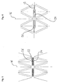
- FIGS. 5 and 6 a second coupling device is shown in which the plug-in elements 22, 24 are provided in the circumferential direction of the stent 10, ie substantially perpendicular to the longitudinal axis 16 of the stent 10.
- the plug-in elements 22, 24 are moved away from each other in the expansion of the stent 10, as in Fig. 6 is shown.
- the plug elements 22, 24 are in this stent 10 in the compressed state of the stent 10 in the approximate position, as in Fig. 5 is shown and move away from each other when the stent 10 is expanded, as in FIG Fig. 6 is shown.
- the detent (s) 26 of the male connector element 22 and the recess (s) 28 of the female plug element 24 are formed so that a latching takes place in the mutually moved away state. It can be formed in the formation of multiple locking lugs 26 and / or recesses 28 a multi-stage latching.
- plug elements 22, 24 are used in combination both in the circumferential direction and in the axial direction.
- different shapes of an expanded stent 10 can be formed by different configuration of the plug elements of a circular shape, as in Fig. 7 is shown.
- stent 10 has three constrictions on its circumference in the expanded state, which are formed by forming different plug-in elements 22, 24.
- other shapes of the expanded stent 10 may be formed by different male members 22, 24, such as an ellipse shape, a cone shape, a waveform, etc.
- the preparation of the stent according to the invention or a preferred Embodiment hereof can take place both from raw material and from flat material, wherein in the latter the stent is later rolled, welded and / or finished.
- the production of the stent can be carried out by means of laser cutting, laser ablation, photochemical etching and / or erosion.
- the production of the stent may also be such that the stent structure is made in an at least partially expanded form and the stent is then reduced to a compressed shape for insertion into the catheter, for example, before it is subsequently at least partially expanded again in the body.
- the invention is particularly useful with balloon expanded stents made of stainless steel, tantalum, niobium, cobalt alloys and other materials such as e.g. Polymers, self-degradable materials (e.g., lactic acid materials or derivatives); and stents of nitinol (nickel-titanium alloys) and / or other self-expanding materials.
- materials such as e.g. Polymers, self-degradable materials (e.g., lactic acid materials or derivatives); and stents of nitinol (nickel-titanium alloys) and / or other self-expanding materials.
- the stent or spreading or support structure according to the invention is particularly preferably used for stabilizing vessels, in particular blood vessels or as a tracheal stent, bronchial stent, transhepatic portosystemic shunt, transhepatic intravenous portosystemic shunt (TIPS), bile duct stent and / or protective device Embolisms (English: Embolic Protective Device).
- the stent or spreading or support structure according to the invention is preferably used as a carrier stent for implants, in particular for a heart valve, a venous valve, a vena cava filter, a prostatic sphincter body and / or as an antireflux stent (gastric valve).
Description
Die Erfindung betrifft einen Stent zum Einsetzen und/oder Expandieren in einem Lumen bzw. zum Implantieren in einen lebenden Körper, mit mindestens zwei Abschnitten einer Stentstruktur, die beim Expandieren des Stents aufeinander zu bewegt werden.The invention relates to a stent for insertion and / or expansion in a lumen or for implanting in a living body, with at least two sections of a stent structure, which are moved towards each other during expansion of the stent.
Stents der oben genannten Art werden verwendet, um ein Lumen bzw. einen Kanal eines lebenden Körpers, wie beispielsweise Blutgefäße, Speiseröhre, Harnröhre oder Nierengänge, durch Expandieren einer im wesentlichen rohrförmigen Wandstruktur des Stents im Inneren des Kanals gegen Kollabieren oder Verschließen zu schützen. Der eingesetzte Stent kann dabei den Strömungsquerschnitt des Lumen für ein darin strömendes Medium vergrößern oder dauerhaft ausreichend groß halten. Ferner werden Stents als Träger von Medikamenten verwendet, die in einem Körperkanal eine zumindest lokale Therapie möglich machen. Stents können darüber hinaus als Aneurismen-Stent bzw. Endoprothese für intrazelebrale Gefäßaussackungen oder als intraluminaler Stent eingesetzt werden. Weiterhin werden Stents bzw. Spreizstrukturen als Träger für Implantate verwendet.Stents of the above type are used to protect a lumen of a living body, such as blood vessels, esophagus, urethra or kidney ducts, from collapsing or occluding by expanding a substantially tubular wall structure of the stent within the channel. The stent used can increase the flow cross-section of the lumen for a medium flowing therein or permanently keep sufficiently large. Furthermore, stents are used as carriers of medicaments which make at least local therapy possible in a body passageway. In addition, stents can be used as aneurysm stent or endoprosthesis for intracular vessel bagging or as an intraluminal stent. Furthermore, stents or spreading structures are used as carriers for implants.
Die Wand- bzw. Stentstruktur solcher Stents weist eine Vielzahl von Stegen auf, die miteinander an Stegverbindern bzw. Knoten verbunden sind. Die Stege sind aus einem flexiblen Material, wie etwa Nitinol oder Edelstahl gestaltet, so dass der Stent insgesamt eine geringfügig flexible Wandstruktur aufweist. Es sind ferngesteuert zu expandierende Stents bekannt, die beispielsweise mittels einer Art Bowdenzug betätigt werden, oder selbstexpandierende Stents, die vorgespannt sind und ihren Durchmesser bei entsprechender Freigabe selbsttätig vergrößern.The wall or stent structure of such stents has a plurality of webs, which are connected to each other at web connectors or nodes. The webs are made of a flexible material, such as Nitinol or stainless steel, so that the stent has a slightly flexible wall structure as a whole. There are remotely controlled to expand stents known, which are operated for example by means of a type Bowden cable, or self-expanding stents, which are biased and their Enlarge diameter automatically with appropriate release.
Damit der gewünschte Strömungsquerschnitt des Lumens sichergestellt ist, ist es wünschenswert, dass ein einmal eingesetzter und expandierter Stent seine Form möglichst dauerhaft beibehält und nicht später weiter expandiert oder komprimiert. Ferner wäre es wünschenswert, wenn der Stent eine vordefinierte Form annehmen und diese dann beibehalten würde.In order to ensure the desired flow cross-section of the lumen, it is desirable for a once inserted and expanded stent to retain its shape as permanently as possible and not further expand or compress later. Further, it would be desirable if the stent took on a predefined shape and then retained it.
Die Aufgabe der Erfindung besteht in der Schaffung eines Stents, bei dem unerwünschte Deformationen zuverlässig verhindert werden kann.The object of the invention is to provide a stent in which unwanted deformations can be reliably prevented.
Diese Aufgabe wird durch den Stent gemäß Anspruch 1 gelöst. Bevorzugte Ausführungsformen der Erfindung sind Gegenstand der Unteransprüche.This object is achieved by the stent according to claim 1. Preferred embodiments of the invention are subject of the dependent claims.
Die Aufgabe ist erfindungsgemäß durch einen Stent. Trägerstruktur zum Einsetzen bzw. Einführen und/oder Expandieren bzw. Stützen bzw. Tragen in einem Lumen gelöst, mit mindestens zwei Abschnitten einer Stentstruktur, die beim Expandieren des Stents im wesentlichen aufeinander zu bewegt werden, bei dem zwischen den beiden Abschnitten mindestens eine Koppeleinrichtung angeordnet ist, mittels der nach zumindest einer vordefinierten Bewegung bzw. Wegstrecke der beiden Abschnitte diese Abschnitte miteinander mit den Merchemalen nach Anspruch 1 gelöst.The object is according to the invention by a stent. Carrier structure for insertion or and / or expanding or supporting or carrying in a lumen, with at least two sections of a stent structure, which are moved towards each other when expanding the stent substantially to each other, arranged at the at least one coupling device between the two sections is, by means of at least one predefined movement or distance of the two sections, these sections with each other with the Merchemalen according to claim 1 solved.
Erfindungsgemäß ist zwischen zwei Abschnitten des Stents bzw. der Spreiz- bzw. Trägerstruktur, welche sich bei einer Expansion des Stents bzw. der Spreiz- bzw. Trägerstruktur relativ zueinander bewegen eine Koppelung vorgesehen, welche die Abschnitte in ihrer versetzten Lage relativ zu einander fixiert und auf diese Weise eine undefinierte weitere Expansion und/oder Kompression des Stents nicht mehr zuläßt. Ferner nehmen die zu bewegenden Abschnitte des Stents aufgrund der erfindungsgemäßen Koppeleinrichtung eine vorbestimmte Lage relativ zueinander ein, so dass der Stent insgesamt mit seiner Vielzahl Abschnitten beim Expandieren ebenfalls in eine vordefinierte Form gebracht wird und in dieser Form auch verharrt.According to the invention, a coupling is provided between two sections of the stent or the spreading or support structure, which move relative to one another during an expansion of the stent or the spreading or support structure, which fixes the sections in their staggered position relative to one another and in this way no longer allows undefined further expansion and / or compression of the stent. Furthermore, due to the coupling device according to the invention, the sections of the stent to be moved assume a predetermined position relative to one another, so that the stent as a whole is likewise brought into a predefined shape with its multiplicity of sections during expansion and also remains in this form.
Bei der Erfindung ist die Koppeleinrichtung mit einem männlichen und einem weiblichen Steckelement gestaltet, von denen insbesondere eines an einem ersten der beiden Abschnitte und das andere an dem zweiten Abschnitt im wesentlichen ortsfest angebracht ist. Die Steckelemente bilden eine kraft- und/oder formschlüssige Verbindung mittels, der die Abschnitte im komprimierten Zustand des Stents relativ zueinander fixiert werden. Eine weitere Expansion oder Kompression würde die vorgesehenen Steckelemente deformieren. Die Steckelemente sind daher gerade derart steif gestaltet, dass eine gewisse Restflexibilität des Stents im expandierten Zustand erhalten bleibt, dass aber dennoch die gewünschte Formgenauigkeit in diesem expandierten Zustand erreicht wird.In the invention, the coupling device is designed with a male and a female plug element, of which in particular one is attached to a first of the two sections and the other to the second section substantially stationary. The plug-in elements form a non-positive and / or positive connection by means of which the sections are fixed relative to one another in the compressed state of the stent. Further expansion or compression would deform the provided plug-in elements. The plug-in elements are therefore designed so stiff that a certain residual flexibility of the stent is maintained in the expanded state, but that nevertheless the desired dimensional accuracy is achieved in this expanded state.
Die Koppeleinrichtung ist mit zwei Steghälften gebildet, die im wesentlichen koaxial ausgerichtet sind und einander gegenüberliegende Endbereiche aufweisen, an denen an einem ersten Endbereich das männliche und an dem zweiten Endbereich das weibliche Steckelement ausgebildet ist. Die Steghälften können bei der Herstellung des erfindungsgemäßen Stents aus einem einzelnen Steg ausgeschnitten und dabei kann an ihnen auch das männliche sowie das weibliche Steckelement ausgebildet werden.The coupling device is formed with two web halves, which are aligned substantially coaxially and have opposite end portions, on which at a first end portion of the male and at the second end portion of the female plug element is formed. The web halves can be cut out of a single web in the production of the stent according to the invention and thereby also the male and the female plug element can be formed on them.
Damit die in der Regel große Anzahl einzelner Koppeleinrichtungen eines erfindungsgemäßen Stents beim Expandieren des Stents alle störungsfrei geschlossen werden können, ist die einzelne Koppeleinrichtung mit einem Führungselement gestaltet, mit dem das männliche Steckelement in das weibliche Steckelement geführt wird, wenn die beiden Abschnitte aufeinander zu bewegt werden.So that the usually large number of individual coupling devices of a stent according to the invention can be closed without disruption during expansion of the stent, the single coupling device is designed with a guide element with which the male plug element is guided into the female plug element when the two sections move towards each other become.
Die Koppeleinrichtung ist ferner mit zwei Steghälften gebildet, die im wesentlichen koaxial ausgerichtet sind und an einander gegenüberliegenden Endbereichen als Führungselement zum einen einen Führungsstab und zum anderen eine Führungsnut aufweisen. Der Führungsstab und die Führungsnut lassen sich besonders kostengünstig während der Herstellung von Stützstegen der Stentstruktur aus dem Material des Stents (z.B. ein Formgedächtniswerkstoff, insbesondere Nitinol) beispielsweise durch einen Laserschweißvorgang ausschneiden. Die Achse der beiden Steghälften kann sich vorteilhaft im wesentlichen parallel zur Längsachse des Stents erstrecken, denn auf diese Weise kann vorteilhafterweise sichergestellt werden, dass während der Expansion des Stents der Führungsstab nahezu nicht gebogen, sondern nur zusammen mit der Führungsnut parallel versetzt wird. Der Führungsstab tritt daher auch aus der Führungsnut radial nicht heraus.The coupling device is further formed with two web halves, which are aligned substantially coaxially and at opposite end regions as a guide element for a guide rod and on the other hand have a guide groove. The guide rod and the guide groove can be cut particularly cost-effectively during the production of support webs of the stent structure from the material of the stent (for example a shape memory material, in particular nitinol), for example by a laser welding process. The axis of the two web halves can advantageously extend substantially parallel to the longitudinal axis of the stent, because in this way it can advantageously be ensured that during the expansion of the stent, the guide rod is almost not bent, but only offset together with the guide groove in parallel. The guide rod therefore also does not pass out of the guide groove radially.
Damit eine unerwünschte Deformation des erfindungsgemäßen Stents und insbesondere von dessen Koppeleinrichtungen zuverlässig verhindert ist, sind jeweils mit dem Führungselement die beiden Abschnitte bereits im nicht expandierten Zustand des Stents relativ zueinander geführt.In order to reliably prevent undesired deformation of the stent according to the invention and in particular of its coupling devices, the two sections are already guided relative to each other with the guide element in the unexpanded state of the stent.
Als formschlüssige Koppelung der Steghälften eines erfindungsgemäßen Stents kann die Koppeleinrichtung mit mindestens einem Hakenelement bzw. Nut/Federelement gestaltet sein, das beispielsweise an einem zugehörigen weiblichen Steckelement verrastet, wenn die beiden Abschnitte aufeinander zu bewegt werden.As a positive coupling of the web halves of a stent according to the invention, the coupling device may be designed with at least one hook element or tongue / groove element, for example, latched to an associated female plug element when the two sections are moved towards each other.
Damit bei dem erfindungsgemäßen Stent sowohl die Stentstruktur als auch die darin vorgesehenen Koppeleinrichtungen in nur einem Arbeitsgang aus dem Material des Stents ausgeschnitten werden können, sind vorzugsweise als einzelnes Strukturelement der Stentstruktur mindestens vier Stege vorgesehen, die an Knoten schwenkbar bzw. biegbar miteinander verbunden sind und im expandierten Zustand des Stents eine geschlossene (im wesentlichen polygonartige) Ring-Form, insbesondere eine Rautenform bilden, in deren Inneren die Koppeleinrichtung angeordnet ist. Darüber hinaus kann die Koppeleinrichtung bei dieser Ausgestaltung mittels zweier Steghälften gebildet sein, die im wesentlichen eine Diagonale innerhalb der Ringform bilden.Thus, in the stent according to the invention both the stent structure and the therein provided coupling devices can be cut out of the material of the stent in only one operation, are preferably provided as a single structural element of the stent structure at least four webs which are pivotally connected to nodes or bendable and in the expanded state of the stent a closed (essentially polygonal) Ring form, in particular form a diamond shape, in the interior of the coupling device is arranged. In addition, the coupling device may be formed in this embodiment by means of two web halves, which form a diagonal substantially within the ring shape.
Hinsichtlich dieser besonders bevorzugten Struktur des erfindungsgemäßen Stents kann die Koppeleinrichtung ferner mit zwei einander gegenüberliegenden Steghälften gebildet sein, die jeweils einzeln zusammen mit zwei benachbarten Stützstegen an einem Knoten der Stentstruktur angelenkt sind.With regard to this particularly preferred structure of the stent according to the invention, the coupling device may further be formed with two opposing web halves which are each articulated individually together with two adjacent support webs at a node of the stent structure.
Gemäß der Erfindung wird weiterhin ein Träger für eine Herzklappe vorgeschlagen, der einen derartigen Stent aufweist.According to the invention, there is further proposed a heart valve carrier having such a stent.
Gemäß der Erfindung wird weiterhin einTräger für eine Venenklappe, einen Vena Cava Filter, einen prostatischen Sphinkterkörper und/oder als Antireflux Stent (Magenventil) vorgeschlagen, der bzw. die einen derartigen Stent aufweist.According to the invention, there is further proposed a venous valve carrier, a vena cava filter, a prostatic sphincter body, and / or an antireflux stent having such a stent.
Nachfolgend wird ein Ausführungsbeispiel eines erfindungsgemäßen Stents anhand der beigefügten schematischen Zeichnungen beispielsweise näher erläutert. Es zeigt:
- Fig. 1
- eine Detailansicht eines Strukturelements eines erfindungsgemäßen Stents im komprimierten Zustand, bei dem eine Koppeleinrichtung in axialer Richtung des Stents angeordnet ist,
- Fig. 2
- die Detailansicht gemäß
Fig. 1 im expandierten Zustand, - Fig. 3
- eine Abwicklung einer Umfangreihe von Strukturelementen eines erfindungsgemäßen Stents im komprimierten Zustand und
- Fig. 4
- die Abwicklung gemäß
Fig. 3 im expandierten Zustand, - Fig. 5
- eine zweite Koppeleinrichtung die in Umfangsrichtung des Stents angeordnet ist,
- Fig. 6
- die in
Fig. 5 gezeigte Koppeleinrichtung, - Fig. 7
- einen weiteren Stent mit einem nicht kreisförmigen Querschnitt.
- Fig. 1
- a detailed view of a structural element of a stent according to the invention in the compressed state, in which a coupling device is arranged in the axial direction of the stent,
- Fig. 2
- the detailed view according to
Fig. 1 in the expanded state, - Fig. 3
- a development of a circumferential row of structural elements of a stent according to the invention in the compressed state and
- Fig. 4
- the settlement according to
Fig. 3 in the expanded state, - Fig. 5
- a second coupling device which is arranged in the circumferential direction of the stent,
- Fig. 6
- in the
Fig. 5 shown coupling device, - Fig. 7
- another stent with a non-circular cross-section.
In den
Die Stützstege 12 erstrecken sich im komprimierten Zustand des Stents 10 im wesentlichen in Richtung einer Längsachse 16 des Stents 10 und bilden dabei eine Art flachgedrückte Raute, in der im Inneren zwei koaxial angeordnete Steghälften 18 und 20 angeordnet sind. Die Steghälften 18 und 20 sind an ihren voneinander abgewandten Enden jeweils an einem der Knoten 14 angelenkt und weisen an ihren zueinander gewandten Endbereichen ein männliches bzw. ein weibliches Steckelement 22 und 24 auf.The
An dem männlichen und dem weiblichen Steckelement 22 bzw. 24 sind jeweils einander gegenüberliegende Anlageflächen ausgebildet, die in dem in
Bei dieser Bewegung wird die aus dem männlichen und dem weiblichen Steckelement 22 bzw. 24 gebildete Steck- bzw. Schnappverbindung zusammengeführt und in dieser Stellung verrastet. Das Verrasten geschieht mittels einer oder mehreren Rastnasen 26, die an dem männlichen Steckelement vorgesehen sind und die jeweils an einer entsprechenden Aussparung 28 des weiblichen Steckelements 24 einrasten. Damit die Rastnasen 26 in das weibliche Steckelement 24 eingeführt werden können, ist dieses mittels zweier Federarme 30 gestaltet, in denen die Aussparungen 28 ausgebildet sind. Die Rastnase(n) 26 ist bzw. sind bevorzugt haken- bzw. doppelhaken- bzw. pfeilförmig während die entsprechende(n) Aussparung(en) 28 eine im wesentlichen komplementäre Form aufweisen.During this movement, the male or
Bei einem selbstexpandierenden Stent 10 sollte dabei die Expansionskraft größer als die Gegenkraft dieser Federarme 30 gegen die Rastnasen 26 sein. Um dies zu erreichen, sollte der letzte Schritt einer Wärmebehandlung eines solchen Stents die Differenz vom Ansetzen des Stents bis zum Einrasten von dessen Schnappverbindungen überbrücken. Ferner kann die Austenit-finish-Temperatur (Af-Temperatur) des Stentmaterials so eingestellt sein, dass das Handhaben des Stents 10 bei normaler Umgebungstemperatur, d.h. einer Temperatur von zirka 20 ° C bis 25 ° C, möglich ist. Fremdgesteuert expandierende Stents 10 werden erst bei der Anwendung des Stents manuell bzw. gesondert expandiert. Bei solches Stents 10 muss sichergestellt sein, dass die Federarme 30 an den Schnappverbindungen beim Expandieren nicht dauerhaft bzw. plastisch verformt werden.In a self-expanding
An dem männlichen Steckelement 22 ist ferner im vordersten Bereich ein Führungsstab 32 ausgebildet, der bereits im komprimierten Zustand des Stents 10 in einer Führungsnut 34 des weiblichen Steckelements 24 geführt und darin weiter verschiebbar ist.On the
Im verrasteten Zustand des männlichen und des weiblichen Steckelements 22 bzw. 24 liegen die zugehörigen, oben genannten Anlageflächen aneinander an und es ist insgesamt eine verrastete Koppeleinrichtung 36 geschaffen. Mit dieser Koppeleinrichtung 36 sind die ansonsten beweglichen, zu den Steghälften 18 und 20 gehörenden Knoten 14 relativ zueinander fixiert und die Stützstege 12 sind in einer im wesentlichen nicht mehr verformbare Rautenform arretiert.In the latched state of the male and female plug-in
Die vielen in Umfangsrichtung des Stents 10 nebeneinander angeordneten Rauten, wie sie in
Da bevorzugt in jeder einzelnen Raute jeweils eine Koppeleinrichtung 36 ein weiteres Verformen der Rautenform verhindert ist die expandierte Gesamtform des Stents 10 fixiert und kann im wesentlichen nicht mehr verändert werden. Eine undefinierte weitere Expansion und/oder Kompression des Stents 10 ist damit sicher verhindert. Es ist jedoch denkbar, Koppeleinrichtungen 36 nur in jeder zweiten oder weiteren Rautenform (bevorzugt im wesentlichen in Umfangsrichtung des Stents regelmäßig) vorzusehen.Since in each individual rhombus in each case a
Es ist weiterhin denkbar, daß entlang der Bewegungsrichtung der Knoten 14 zueinander eine Vielzahl von Rastmöglichkeiten vorgesehen ist, z.B. durch Hintereinander-Vorsehen einer Vielzahl von Rastnasen 26 und/oder entsprechenden Aussparungen 28, so daß der Stent 10 in verschiedenen Expansionsgraden bzw. - zuständen expandiert angeordnet sein kann. In anderen Worten kann durch ein Vorsehen von Kopplungseinrichtungen an verschiedenen axialen Positionen bzw. Expansionsgraden sichergestellt werden, daß der Stent bevorzugt in verschiedenen Expansionszuständen (in denen die Knoten um verschiedene Wegstrecken X1...Xn zueinander hin bewegt sind) verrastet werden kann.It is also conceivable that along the direction of movement of the
In den
Demgemäß sind die Rastnase(n) 26 des mänlichen Steckelements 22 und die Aussparung(en) 28 des weiblichen Steckelements 24 so ausgebildet, dass eine Verrastung im voneinander weg bewegten Zustand erfolgt. Dabei kann bei der Ausbildung mehrerer Rastnasen 26 und/oder Aussparungen 28 eine mehrstufige Verrastung gebildet werden.Accordingly, the detent (s) 26 of the
Es können auch die Steckelemente 22, 24 sowohl in Umfangsrichtung als auch in axialer Richtung in Kombination eingesetzt werden. Außerdem können durch unterschiedliche Ausbildung der Steckelemente von einer Kreisform abweichende Formen eines expandierten Stents 10 gebildet werden, wie in
Der in
Die Herstellung des Stents gemäß der Erfindung oder eine bevorzugte Ausführungsform hiervon kann sowohl aus Rohmaterial als auch aus Flachmaterial erfolgen wobei bei letzterem der Stent später gerollt, geschweißt und/oder endbearbeitet wird. Weiterhin kann die Herstellung des Stents mittels Laserschneiden, Laserabtrag, photochemisches Ätzen und/oder Erodieren erfolgen. Weiterhin kann die Herstellung des Stents auch derart erfolgen, daß die Stentstruktur in einer zumindest teilweise expandierten Form gefertigt wird und der Stent anschließend zum Einführen z.B. in den Katheter auf eine komprimierte Form verkleinert wird, bevor er nachfolgend im Körper wieder zumindest teilweise expandiert wird.The preparation of the stent according to the invention or a preferred Embodiment hereof can take place both from raw material and from flat material, wherein in the latter the stent is later rolled, welded and / or finished. Furthermore, the production of the stent can be carried out by means of laser cutting, laser ablation, photochemical etching and / or erosion. Furthermore, the production of the stent may also be such that the stent structure is made in an at least partially expanded form and the stent is then reduced to a compressed shape for insertion into the catheter, for example, before it is subsequently at least partially expanded again in the body.
Die Erfindung kann besonders sinnvoll bei ballonexpandierten Stents aus rostfreiem Edelstahl, Tantal, Niob, Kobaltlegierungen und anderen Werkstoffen wie z.B. Polymeren, selbstabbaubaren Werkstoffen (z.B. Milchsäure-Werkstoffen bzw. - Derivate), sowie bei Stents aus Nitinol (Nickel-Titan-Legierungen) und/oder aus anderen selbstexpandierbaren Werkstoffen bzw. Formgedächniswerkstoffen verwendet werden.The invention is particularly useful with balloon expanded stents made of stainless steel, tantalum, niobium, cobalt alloys and other materials such as e.g. Polymers, self-degradable materials (e.g., lactic acid materials or derivatives); and stents of nitinol (nickel-titanium alloys) and / or other self-expanding materials.
Besonders bevorzugt wird der erfindungsgemäße Stent bzw. Spreiz- bzw. Trägerstruktur verwendet zum Stabilisieren von Gefäßen, insbesondere von Blutgefäßen oder als Trachealstent, Bronchial-Stent, transhepatischer Portosytemischer Shunt, Transhepatischer Intravenöser Portosytemischer Shunt (TIPS), Gallengang-Stent und/oder Schutzvorrichtung gegen Embolien (Englisch: Embolic Protective Device). Weiterhin bevorzugt wird der erfindungsgemäße Stent bzw. Spreiz- bzw. Trägerstruktur verwendet als Träger-Stent für Implantate insbesondere für eine Herzklappe, eine Venenklappe, einen Vena Cava Filter, einen prostatischen Sphinkterkörper und/oder als Antireflux Stent (Magenventil).The stent or spreading or support structure according to the invention is particularly preferably used for stabilizing vessels, in particular blood vessels or as a tracheal stent, bronchial stent, transhepatic portosystemic shunt, transhepatic intravenous portosystemic shunt (TIPS), bile duct stent and / or protective device Embolisms (English: Embolic Protective Device). Furthermore, the stent or spreading or support structure according to the invention is preferably used as a carrier stent for implants, in particular for a heart valve, a venous valve, a vena cava filter, a prostatic sphincter body and / or as an antireflux stent (gastric valve).
- 1010
- Stentstent
- 1212
- Stützstegsupporting web
- 1414
- Knotennode
- 1616
- Längsachselongitudinal axis
- 1818
- SteghälfteSteg half
- 2020
- SteghälfteSteg half
- 2222
- männliches Steckelementmale plug element
- 2424
- weibliches Steckelementfemale plug element
- 2626
- Rastnaselocking lug
- 2828
- Aussparungrecess
- 3030
- Federarmspring arm
- 3232
- FührungsstabCorporate Office
- 3434
- Führungsnutguide
- 3636
- Koppeleinrichtungcoupling device
- XX
- Abstand zwischen AnlageflächenDistance between contact surfaces
Claims (10)
- A stent (10) for insertion and/or expansion in a lumen, with at least two portions (14) of a stent structure, which upon expansion of the stent (10) are moved toward each other,
wherein at least one coupling device (36) is arranged between the two por tions (14), by means of which the portions (14) are coupled to each other after at least one predefined movement (X) of the two portions (14),
wherein a removal of the two portions (14) away from each other is prevented by the coupling device (36) when the coupling device (36) couples the portions (14) to each other after the predefined movement (X) of the two portions (14), so that the expanded overall form of the stent (10) is fixed such that it cannot be changed any more,
wherein the coupling device (36) is formed with two web halves (18; 20) coaxially aligned and having male and female connection elements (22, 24) at mutually opposite end regions thereof, one or more latching noses (26) being provided on the male connection element (22) and one or more corresponding recesses (28) being provided on the female connection element (24), characterized in that a guide rod (32) is formed on the male connection element (22) in the frontmost region thereof, the guide rod (32) being guided in a guide groove (34) of the female connection element (24) and further slidable therein already in a compressed state of the stent (10). - The stent (10) according to claim 1, further with at least portions of a stent structure, which are moved away from each other upon expansion of the stent (10),
wherein at least one second coupling device is arranged between the two portions, by means of which the portions are coupled to each other after at least one predefined movement (X) of the two portions such that a movement of the two portions toward each other is prevented. - The stent according to claim 1 or 2, wherein one of the male and female connection elements (22; 24) is stationarily attached to a first one of the two portions (14) and the other to the second portion (14).
- The stent according to one of the preceding claims, wherein at least four support webs (12) are provided, which are pivotally connected to each other at knots (14) and form a closed ring shape in the expanded state of the stent (10), in the interior of which the coupling device (36) is arranged.
- The stent according to claim 4, wherein the closed ring shape forms a lozenge shape.
- The stent according to one of the preceding claims, wherein each web half (18; 20) is hinged to two adjacent support webs (12) at a knot (14) of the stent structure.
- The stent according to one of the preceding claims, wherein the coupling device (36) substantially extends in the direction of a longitudinal axis (16) of the stent (10).
- The stent according to one of claims 2 to 6, wherein the second coupling device substantially extends in the circumferential direction of the stent (10).
- A carrier for a heart valve, with at least one stent according to one of the preceding claims.
- A carrier for a venous valve, vena cava filter, prostatic sphincter body and/or antireflux stent, with at least one stent according to one of the preceding claims.
Priority Applications (1)
| Application Number | Priority Date | Filing Date | Title |
|---|---|---|---|
| EP05001229A EP1557138B1 (en) | 2004-01-21 | 2005-01-21 | Expandable stent with coupling device |
Applications Claiming Priority (5)
| Application Number | Priority Date | Filing Date | Title |
|---|---|---|---|
| DE102004003093A DE102004003093B4 (en) | 2004-01-21 | 2004-01-21 | Stent for insertion and expansion in a lumen |
| DE102004003093 | 2004-01-21 | ||
| EP04026619 | 2004-11-09 | ||
| EP04026619 | 2004-11-09 | ||
| EP05001229A EP1557138B1 (en) | 2004-01-21 | 2005-01-21 | Expandable stent with coupling device |
Publications (2)
| Publication Number | Publication Date |
|---|---|
| EP1557138A1 EP1557138A1 (en) | 2005-07-27 |
| EP1557138B1 true EP1557138B1 (en) | 2012-12-05 |
Family
ID=34636837
Family Applications (1)
| Application Number | Title | Priority Date | Filing Date |
|---|---|---|---|
| EP05001229A Expired - Fee Related EP1557138B1 (en) | 2004-01-21 | 2005-01-21 | Expandable stent with coupling device |
Country Status (1)
| Country | Link |
|---|---|
| EP (1) | EP1557138B1 (en) |
Cited By (14)
| Publication number | Priority date | Publication date | Assignee | Title |
|---|---|---|---|---|
| US8828079B2 (en) | 2007-07-26 | 2014-09-09 | Boston Scientific Scimed, Inc. | Circulatory valve, system and method |
| US10856984B2 (en) | 2017-08-25 | 2020-12-08 | Neovasc Tiara Inc. | Sequentially deployed transcatheter mitral valve prosthesis |
| US10940001B2 (en) | 2012-05-30 | 2021-03-09 | Neovasc Tiara Inc. | Methods and apparatus for loading a prosthesis onto a delivery system |
| US11311376B2 (en) | 2019-06-20 | 2022-04-26 | Neovase Tiara Inc. | Low profile prosthetic mitral valve |
| US11357622B2 (en) | 2016-01-29 | 2022-06-14 | Neovase Tiara Inc. | Prosthetic valve for avoiding obstruction of outflow |
| US11389291B2 (en) | 2013-04-04 | 2022-07-19 | Neovase Tiara Inc. | Methods and apparatus for delivering a prosthetic valve to a beating heart |
| US11413139B2 (en) | 2011-11-23 | 2022-08-16 | Neovasc Tiara Inc. | Sequentially deployed transcatheter mitral valve prosthesis |
| US11419720B2 (en) | 2010-05-05 | 2022-08-23 | Neovasc Tiara Inc. | Transcatheter mitral valve prosthesis |
| US11464631B2 (en) | 2016-11-21 | 2022-10-11 | Neovasc Tiara Inc. | Methods and systems for rapid retraction of a transcatheter heart valve delivery system |
| US11491006B2 (en) | 2019-04-10 | 2022-11-08 | Neovasc Tiara Inc. | Prosthetic valve with natural blood flow |
| US11497602B2 (en) | 2012-02-14 | 2022-11-15 | Neovasc Tiara Inc. | Methods and apparatus for engaging a valve prosthesis with tissue |
| US11602429B2 (en) | 2019-04-01 | 2023-03-14 | Neovasc Tiara Inc. | Controllably deployable prosthetic valve |
| US11737872B2 (en) | 2018-11-08 | 2023-08-29 | Neovasc Tiara Inc. | Ventricular deployment of a transcatheter mitral valve prosthesis |
| US11779742B2 (en) | 2019-05-20 | 2023-10-10 | Neovasc Tiara Inc. | Introducer with hemostasis mechanism |
Families Citing this family (8)
| Publication number | Priority date | Publication date | Assignee | Title |
|---|---|---|---|---|
| US9585743B2 (en) | 2006-07-31 | 2017-03-07 | Edwards Lifesciences Cardiaq Llc | Surgical implant devices and methods for their manufacture and use |
| EP2068765B1 (en) | 2006-07-31 | 2018-05-09 | Syntheon TAVR, LLC | Sealable endovascular implants |
| US9408607B2 (en) | 2009-07-02 | 2016-08-09 | Edwards Lifesciences Cardiaq Llc | Surgical implant devices and methods for their manufacture and use |
| US9566178B2 (en) | 2010-06-24 | 2017-02-14 | Edwards Lifesciences Cardiaq Llc | Actively controllable stent, stent graft, heart valve and method of controlling same |
| EP2438872B1 (en) * | 2010-10-08 | 2020-11-04 | Biotronik AG | Medical implant, in particular a stent, for implantation in an animal body and/or human body |
| US9827093B2 (en) | 2011-10-21 | 2017-11-28 | Edwards Lifesciences Cardiaq Llc | Actively controllable stent, stent graft, heart valve and method of controlling same |
| CA2865013C (en) | 2012-02-22 | 2020-12-15 | Syntheon Cardiology, Llc | Actively controllable stent, stent graft, heart valve and method of controlling same |
| CN112638327A (en) * | 2018-06-20 | 2021-04-09 | W.L.戈尔及同仁股份有限公司 | Support structure for implantable device having region of enhanced compressive stiffness |
Citations (3)
| Publication number | Priority date | Publication date | Assignee | Title |
|---|---|---|---|---|
| US5019102A (en) * | 1987-12-10 | 1991-05-28 | Eberhard Hoene | Anti-refluxive internal ureteral stent with a dynamic hood-valve at the vesical end for prevention of urinary reflux into the upper urinary tract upon increase of vesical pressure |
| DE19728337A1 (en) * | 1997-07-03 | 1999-01-07 | Inst Mikrotechnik Mainz Gmbh | Implantable stent |
| US6245102B1 (en) * | 1997-05-07 | 2001-06-12 | Iowa-India Investments Company Ltd. | Stent, stent graft and stent valve |
Family Cites Families (3)
| Publication number | Priority date | Publication date | Assignee | Title |
|---|---|---|---|---|
| US6623521B2 (en) | 1998-02-17 | 2003-09-23 | Md3, Inc. | Expandable stent with sliding and locking radial elements |
| US6540777B2 (en) | 2001-02-15 | 2003-04-01 | Scimed Life Systems, Inc. | Locking stent |
| DE202004000896U1 (en) * | 2004-01-21 | 2004-03-18 | Admedes Schuessler Gmbh | Stent, comprising bridge elements divided into two parts, joined by engaging matching front areas |
-
2005
- 2005-01-21 EP EP05001229A patent/EP1557138B1/en not_active Expired - Fee Related
Patent Citations (3)
| Publication number | Priority date | Publication date | Assignee | Title |
|---|---|---|---|---|
| US5019102A (en) * | 1987-12-10 | 1991-05-28 | Eberhard Hoene | Anti-refluxive internal ureteral stent with a dynamic hood-valve at the vesical end for prevention of urinary reflux into the upper urinary tract upon increase of vesical pressure |
| US6245102B1 (en) * | 1997-05-07 | 2001-06-12 | Iowa-India Investments Company Ltd. | Stent, stent graft and stent valve |
| DE19728337A1 (en) * | 1997-07-03 | 1999-01-07 | Inst Mikrotechnik Mainz Gmbh | Implantable stent |
Cited By (18)
| Publication number | Priority date | Publication date | Assignee | Title |
|---|---|---|---|---|
| US8828079B2 (en) | 2007-07-26 | 2014-09-09 | Boston Scientific Scimed, Inc. | Circulatory valve, system and method |
| US11419720B2 (en) | 2010-05-05 | 2022-08-23 | Neovasc Tiara Inc. | Transcatheter mitral valve prosthesis |
| US11413139B2 (en) | 2011-11-23 | 2022-08-16 | Neovasc Tiara Inc. | Sequentially deployed transcatheter mitral valve prosthesis |
| US11497602B2 (en) | 2012-02-14 | 2022-11-15 | Neovasc Tiara Inc. | Methods and apparatus for engaging a valve prosthesis with tissue |
| US11617650B2 (en) | 2012-05-30 | 2023-04-04 | Neovasc Tiara Inc. | Methods and apparatus for loading a prosthesis onto a delivery system |
| US10940001B2 (en) | 2012-05-30 | 2021-03-09 | Neovasc Tiara Inc. | Methods and apparatus for loading a prosthesis onto a delivery system |
| US11389294B2 (en) | 2012-05-30 | 2022-07-19 | Neovasc Tiara Inc. | Methods and apparatus for loading a prosthesis onto a delivery system |
| US11389291B2 (en) | 2013-04-04 | 2022-07-19 | Neovase Tiara Inc. | Methods and apparatus for delivering a prosthetic valve to a beating heart |
| US11357622B2 (en) | 2016-01-29 | 2022-06-14 | Neovase Tiara Inc. | Prosthetic valve for avoiding obstruction of outflow |
| US11464631B2 (en) | 2016-11-21 | 2022-10-11 | Neovasc Tiara Inc. | Methods and systems for rapid retraction of a transcatheter heart valve delivery system |
| US10856984B2 (en) | 2017-08-25 | 2020-12-08 | Neovasc Tiara Inc. | Sequentially deployed transcatheter mitral valve prosthesis |
| US11793640B2 (en) | 2017-08-25 | 2023-10-24 | Neovasc Tiara Inc. | Sequentially deployed transcatheter mitral valve prosthesis |
| US11737872B2 (en) | 2018-11-08 | 2023-08-29 | Neovasc Tiara Inc. | Ventricular deployment of a transcatheter mitral valve prosthesis |
| US11602429B2 (en) | 2019-04-01 | 2023-03-14 | Neovasc Tiara Inc. | Controllably deployable prosthetic valve |
| US11491006B2 (en) | 2019-04-10 | 2022-11-08 | Neovasc Tiara Inc. | Prosthetic valve with natural blood flow |
| US11779742B2 (en) | 2019-05-20 | 2023-10-10 | Neovasc Tiara Inc. | Introducer with hemostasis mechanism |
| US11311376B2 (en) | 2019-06-20 | 2022-04-26 | Neovase Tiara Inc. | Low profile prosthetic mitral valve |
| US11931254B2 (en) | 2019-06-20 | 2024-03-19 | Neovasc Tiara Inc. | Low profile prosthetic mitral valve |
Also Published As
| Publication number | Publication date |
|---|---|
| EP1557138A1 (en) | 2005-07-27 |
Similar Documents
| Publication | Publication Date | Title |
|---|---|---|
| EP1557138B1 (en) | Expandable stent with coupling device | |
| DE102004003093B4 (en) | Stent for insertion and expansion in a lumen | |
| DE102009060228B4 (en) | Medical devices | |
| DE60206694T2 (en) | Balloon-actuated stent with lockable elements | |
| DE69928915T2 (en) | EXPANDABLE UNIT CELL AND INTRALUMINARY STENT | |
| DE60121947T2 (en) | INTRALUMINAL STENT | |
| DE602004012037T2 (en) | Covering device for an aneurysm neck | |
| DE69829494T2 (en) | SUBSEQUENT INTRALUMINAL STENTS | |
| DE69828220T2 (en) | Expandable intraluminal endoprosthesis | |
| EP0536610B1 (en) | Stenosis dilatation device | |
| DE102008010507B3 (en) | Stent and method of making such a stent | |
| EP0734698B2 (en) | Stent for transluminal implantation into hollow organs | |
| DE69533289T2 (en) | ARRANGEMENT PROCESS OF A COVERED, ENDOLUMINARY STENT | |
| EP3217927B1 (en) | Stent | |
| DE60211999T2 (en) | Flexible stent | |
| DE10109508A1 (en) | Longitudinally flexible stent | |
| EP0481365A1 (en) | Device for expanding a stenosis in a body duct | |
| CH693441A5 (en) | A flexible expandable stent. | |
| EP3213714A1 (en) | Insertion catheter and catheter assembly | |
| EP2799036A1 (en) | Intraluminal endoprosthesis and method for production thereof | |
| EP1555959B1 (en) | Stent to be implanted within or around a hollow organ | |
| EP1844740B1 (en) | Self-expanding stent with spring structure | |
| DE69924260T2 (en) | EXPANDABLE STENT FOR SMALL-POLE VESSELS | |
| DE202004000896U1 (en) | Stent, comprising bridge elements divided into two parts, joined by engaging matching front areas | |
| EP1491161B1 (en) | Flexible shaft |
Legal Events
| Date | Code | Title | Description |
|---|---|---|---|
| PUAI | Public reference made under article 153(3) epc to a published international application that has entered the european phase |
Free format text: ORIGINAL CODE: 0009012 |
|
| AK | Designated contracting states |
Kind code of ref document: A1 Designated state(s): AT BE BG CH CY CZ DE DK EE ES FI FR GB GR HU IE IS IT LI LT LU MC NL PL PT RO SE SI SK TR |
|
| AX | Request for extension of the european patent |
Extension state: AL BA HR LV MK YU |
|
| 17P | Request for examination filed |
Effective date: 20050908 |
|
| AKX | Designation fees paid |
Designated state(s): DE FR GB |
|
| 17Q | First examination report despatched |
Effective date: 20070327 |
|
| REG | Reference to a national code |
Ref country code: DE Ref legal event code: R079 Ref document number: 502005013309 Country of ref document: DE Free format text: PREVIOUS MAIN CLASS: A61F0002060000 Ipc: A61F0002900000 |
|
| GRAP | Despatch of communication of intention to grant a patent |
Free format text: ORIGINAL CODE: EPIDOSNIGR1 |
|
| RIC1 | Information provided on ipc code assigned before grant |
Ipc: A61F 2/90 20060101AFI20120621BHEP |
|
| GRAS | Grant fee paid |
Free format text: ORIGINAL CODE: EPIDOSNIGR3 |
|
| GRAA | (expected) grant |
Free format text: ORIGINAL CODE: 0009210 |
|
| AK | Designated contracting states |
Kind code of ref document: B1 Designated state(s): DE FR GB |
|
| REG | Reference to a national code |
Ref country code: GB Ref legal event code: FG4D Free format text: NOT ENGLISH |
|
| REG | Reference to a national code |
Ref country code: DE Ref legal event code: R096 Ref document number: 502005013309 Country of ref document: DE Effective date: 20130131 |
|
| PLBE | No opposition filed within time limit |
Free format text: ORIGINAL CODE: 0009261 |
|
| STAA | Information on the status of an ep patent application or granted ep patent |
Free format text: STATUS: NO OPPOSITION FILED WITHIN TIME LIMIT |
|
| 26N | No opposition filed |
Effective date: 20130906 |
|
| REG | Reference to a national code |
Ref country code: DE Ref legal event code: R097 Ref document number: 502005013309 Country of ref document: DE Effective date: 20130906 |
|
| PGFP | Annual fee paid to national office [announced via postgrant information from national office to epo] |
Ref country code: GB Payment date: 20141104 Year of fee payment: 11 Ref country code: FR Payment date: 20141028 Year of fee payment: 11 |
|
| PGFP | Annual fee paid to national office [announced via postgrant information from national office to epo] |
Ref country code: DE Payment date: 20160126 Year of fee payment: 12 |
|
| GBPC | Gb: european patent ceased through non-payment of renewal fee |
Effective date: 20160121 |
|
| REG | Reference to a national code |
Ref country code: FR Ref legal event code: ST Effective date: 20160930 |
|
| PG25 | Lapsed in a contracting state [announced via postgrant information from national office to epo] |
Ref country code: GB Free format text: LAPSE BECAUSE OF NON-PAYMENT OF DUE FEES Effective date: 20160121 |
|
| PG25 | Lapsed in a contracting state [announced via postgrant information from national office to epo] |
Ref country code: FR Free format text: LAPSE BECAUSE OF NON-PAYMENT OF DUE FEES Effective date: 20160201 |
|
| REG | Reference to a national code |
Ref country code: DE Ref legal event code: R119 Ref document number: 502005013309 Country of ref document: DE |
|
| PG25 | Lapsed in a contracting state [announced via postgrant information from national office to epo] |
Ref country code: DE Free format text: LAPSE BECAUSE OF NON-PAYMENT OF DUE FEES Effective date: 20170801 |