EP1555730A1 - Connector and coaxial cable with outer conductor cylindral section axial compression connection - Google Patents
Connector and coaxial cable with outer conductor cylindral section axial compression connection Download PDFInfo
- Publication number
- EP1555730A1 EP1555730A1 EP04027657A EP04027657A EP1555730A1 EP 1555730 A1 EP1555730 A1 EP 1555730A1 EP 04027657 A EP04027657 A EP 04027657A EP 04027657 A EP04027657 A EP 04027657A EP 1555730 A1 EP1555730 A1 EP 1555730A1
- Authority
- EP
- European Patent Office
- Prior art keywords
- outer conductor
- connector body
- connector
- coaxial cable
- cylindrical section
- Prior art date
- Legal status (The legal status is an assumption and is not a legal conclusion. Google has not performed a legal analysis and makes no representation as to the accuracy of the status listed.)
- Withdrawn
Links
- 239000004020 conductor Substances 0.000 title claims abstract description 97
- 230000006835 compression Effects 0.000 title claims abstract description 24
- 238000007906 compression Methods 0.000 title claims abstract description 24
- 239000007787 solid Substances 0.000 claims abstract description 24
- 230000000717 retained effect Effects 0.000 claims abstract 4
- 239000000463 material Substances 0.000 claims description 12
- 238000000034 method Methods 0.000 claims description 10
- 239000012212 insulator Substances 0.000 claims description 5
- RYGMFSIKBFXOCR-UHFFFAOYSA-N Copper Chemical compound [Cu] RYGMFSIKBFXOCR-UHFFFAOYSA-N 0.000 claims description 3
- 229910052802 copper Inorganic materials 0.000 claims description 3
- 239000010949 copper Substances 0.000 claims description 3
- 230000007704 transition Effects 0.000 claims description 2
- 229910000881 Cu alloy Inorganic materials 0.000 claims 1
- 238000002347 injection Methods 0.000 claims 1
- 239000007924 injection Substances 0.000 claims 1
- 238000001746 injection moulding Methods 0.000 claims 1
- 239000002991 molded plastic Substances 0.000 claims 1
- 239000004033 plastic Substances 0.000 claims 1
- 238000004519 manufacturing process Methods 0.000 abstract description 4
- 239000003989 dielectric material Substances 0.000 description 4
- 238000002788 crimping Methods 0.000 description 3
- 238000003780 insertion Methods 0.000 description 3
- 230000037431 insertion Effects 0.000 description 3
- 238000013459 approach Methods 0.000 description 2
- 230000008901 benefit Effects 0.000 description 2
- 230000005540 biological transmission Effects 0.000 description 2
- 230000008595 infiltration Effects 0.000 description 2
- 238000001764 infiltration Methods 0.000 description 2
- 238000009434 installation Methods 0.000 description 2
- 238000012986 modification Methods 0.000 description 2
- 230000004048 modification Effects 0.000 description 2
- 229920000642 polymer Polymers 0.000 description 2
- 230000001681 protective effect Effects 0.000 description 2
- 239000011800 void material Substances 0.000 description 2
- XLYOFNOQVPJJNP-UHFFFAOYSA-N water Substances O XLYOFNOQVPJJNP-UHFFFAOYSA-N 0.000 description 2
- 238000000429 assembly Methods 0.000 description 1
- 230000000712 assembly Effects 0.000 description 1
- 230000015556 catabolic process Effects 0.000 description 1
- 230000000295 complement effect Effects 0.000 description 1
- 230000007812 deficiency Effects 0.000 description 1
- 238000006731 degradation reaction Methods 0.000 description 1
- 239000012530 fluid Substances 0.000 description 1
- 239000011888 foil Substances 0.000 description 1
- 230000013011 mating Effects 0.000 description 1
- -1 metallic braid Substances 0.000 description 1
- 230000005012 migration Effects 0.000 description 1
- 238000013508 migration Methods 0.000 description 1
- 230000008569 process Effects 0.000 description 1
- 230000009467 reduction Effects 0.000 description 1
- 238000007789 sealing Methods 0.000 description 1
- 238000005476 soldering Methods 0.000 description 1
- 238000009966 trimming Methods 0.000 description 1
Images


Classifications
-
- H—ELECTRICITY
- H01—ELECTRIC ELEMENTS
- H01R—ELECTRICALLY-CONDUCTIVE CONNECTIONS; STRUCTURAL ASSOCIATIONS OF A PLURALITY OF MUTUALLY-INSULATED ELECTRICAL CONNECTING ELEMENTS; COUPLING DEVICES; CURRENT COLLECTORS
- H01R9/00—Structural associations of a plurality of mutually-insulated electrical connecting elements, e.g. terminal strips or terminal blocks; Terminals or binding posts mounted upon a base or in a case; Bases therefor
- H01R9/03—Connectors arranged to contact a plurality of the conductors of a multiconductor cable, e.g. tapping connections
- H01R9/05—Connectors arranged to contact a plurality of the conductors of a multiconductor cable, e.g. tapping connections for coaxial cables
-
- H—ELECTRICITY
- H01—ELECTRIC ELEMENTS
- H01R—ELECTRICALLY-CONDUCTIVE CONNECTIONS; STRUCTURAL ASSOCIATIONS OF A PLURALITY OF MUTUALLY-INSULATED ELECTRICAL CONNECTING ELEMENTS; COUPLING DEVICES; CURRENT COLLECTORS
- H01R24/00—Two-part coupling devices, or either of their cooperating parts, characterised by their overall structure
- H01R24/38—Two-part coupling devices, or either of their cooperating parts, characterised by their overall structure having concentrically or coaxially arranged contacts
- H01R24/40—Two-part coupling devices, or either of their cooperating parts, characterised by their overall structure having concentrically or coaxially arranged contacts specially adapted for high frequency
- H01R24/56—Two-part coupling devices, or either of their cooperating parts, characterised by their overall structure having concentrically or coaxially arranged contacts specially adapted for high frequency specially adapted to a specific shape of cables, e.g. corrugated cables, twisted pair cables, cables with two screens or hollow cables
- H01R24/564—Corrugated cables
-
- H—ELECTRICITY
- H01—ELECTRIC ELEMENTS
- H01R—ELECTRICALLY-CONDUCTIVE CONNECTIONS; STRUCTURAL ASSOCIATIONS OF A PLURALITY OF MUTUALLY-INSULATED ELECTRICAL CONNECTING ELEMENTS; COUPLING DEVICES; CURRENT COLLECTORS
- H01R2103/00—Two poles
-
- Y—GENERAL TAGGING OF NEW TECHNOLOGICAL DEVELOPMENTS; GENERAL TAGGING OF CROSS-SECTIONAL TECHNOLOGIES SPANNING OVER SEVERAL SECTIONS OF THE IPC; TECHNICAL SUBJECTS COVERED BY FORMER USPC CROSS-REFERENCE ART COLLECTIONS [XRACs] AND DIGESTS
- Y10—TECHNICAL SUBJECTS COVERED BY FORMER USPC
- Y10S—TECHNICAL SUBJECTS COVERED BY FORMER USPC CROSS-REFERENCE ART COLLECTIONS [XRACs] AND DIGESTS
- Y10S439/00—Electrical connectors
- Y10S439/933—Special insulation
- Y10S439/936—Potting material or coating, e.g. grease, insulative coating, sealant or, adhesive
-
- Y—GENERAL TAGGING OF NEW TECHNOLOGICAL DEVELOPMENTS; GENERAL TAGGING OF CROSS-SECTIONAL TECHNOLOGIES SPANNING OVER SEVERAL SECTIONS OF THE IPC; TECHNICAL SUBJECTS COVERED BY FORMER USPC CROSS-REFERENCE ART COLLECTIONS [XRACs] AND DIGESTS
- Y10—TECHNICAL SUBJECTS COVERED BY FORMER USPC
- Y10T—TECHNICAL SUBJECTS COVERED BY FORMER US CLASSIFICATION
- Y10T29/00—Metal working
- Y10T29/49—Method of mechanical manufacture
- Y10T29/49002—Electrical device making
- Y10T29/49117—Conductor or circuit manufacturing
- Y10T29/49204—Contact or terminal manufacturing
Definitions
- the invention relates to connectors for coaxial cable. More particularly the invention relates to cost effective connectors and a coaxial cable adapted for interconnection using axial compression along a cylindrical section formed at a peak of annular corrugation(s) in the outer conductor of the coaxial cable.
- Transmission line cables employing solid outer conductors have improved performance compared to cables with other types of outer conductors such as metallic braid, foil, etc.
- Solid outer conductor coaxial cables are available in various forms such as smooth wall, annular corrugated, and helical corrugated. Smooth wall cable has the lowest materials cost but is relatively inflexible, limiting use of smooth wall cable where other than straight cable runs are required.
- Helical cable is flexible and relatively easy to securely terminate via connectors that thread into the helical cable corrugations.
- the helical cable profile also provides a path for water infiltration into the cable.
- Annular cable is flexible and has improved resistance to water infiltration.
- Annular coaxial cables are typically terminated using connectors that incorporate a mechanical clamp between the connector and the lip of the outer conductor.
- the mechanical clamp assemblies are relatively expensive, frequently requiring complex manufacturing operations, precision threaded surfaces and or multiple sealing gaskets.
- soldered connectors A relatively inexpensive alternative to mechanical clamp connectors is soldered connectors.
- Prior soldered connectors create an interconnection that is difficult to prepare with consistent quality and even when optimally prepared results in an interconnection with limited mechanical strength. Further, heat from the soldering process may damage cable dielectric and or sheathing material.
- Crimping is a form of compression where the compressive force is applied in a radial direction.
- Crimping a solid or stranded wire places a non-compressible core at the center of the crimp. This allows the crimp die to compress the connector body around the solid core at high pressure.
- the connector body is permanently deformed to conform to the solid mass of the wire, resulting in a strong mechanical and electrical bond.
- the strength of the bond in tension approaches the ultimate tensile strength of the wire.
- the absence of voids or air pockets in the crimp area prevents the migration of corrosive fluids within the interface.
- the high residual stress, in the material of the connector body keeps the contact resistance low and stable.
- Crimping braided outer conductors is more problematic.
- a support sleeve of one form or another may be used.
- the braid is captured in a layer between a tubular outer ferrule and the connector body. This crimp is not considered highly reliable. There are typically large voids in the interface allowing for corrosive degradation of the contact surfaces. The mechanical pull strength of the joint does not approach the strength of the wire. Finally, the connection allows relative movement between all 3 components, which results in a very poor, noisy electrical connection.
- tubular support sleeves would require a sleeve that significantly changes the internal dimensions of the cable, causing an RF impedance discontinuity.
- an external mating sleeve adapted to key to the corrugation pattern has been used in a crimp configuration.
- the level of crimp force applicable before the outer conductor deforms is limited, thereby limiting the strength of the resulting interconnection.
- the present invention applies axial, rather than radial, mechanical compression forces to connector components to create a radial compression interconnection between a connector and the outer conductor of a coaxial cable.
- a first embodiment of the invention is shown in figures 1 and 2.
- a typical annular corrugated coaxial transmission line cable suitable for use with the invention is LDF4 manufactured by the assignee of the invention, Andrew Corporation of Orland Park, Illinois.
- the cable 1 has an outer conductor 3 with annular corrugations and an inner conductor 5 surrounded by dielectric material 7.
- any outer protective sheath of the coaxial cable 1 is stripped back and the cable end 9 inserted through a sleeve 11.
- the sleeve 11 may be configured with a sleeve bore 12 having a wider sleeve cable end 13 diameter that transitions to a sleeve connector end 15 diameter which extends to the sleeve connector end 15.
- the sleeve cable end 13 diameter may be, for example, adapted to accept insertion of the cable 1 with the outer protective sheath in place.
- the sleeve connector end 15 diameter is only slightly larger than the diameter of the outer conductor 3, allowing insertion of the outer conductor 3.
- the outer conductor 3 is flared after insertion through the sleeve, creating a flared end 17 which prevents removal of the cable 1 through the sleeve bore 12.
- a connector body 19 is configured to have a complementary outer conductor seat 21 with an outer diameter which creates an interference fit between the thickness of the outer conductor 3 and the sleeve connector end 15 diameter.
- a connector body bore 23 of the connector body 19 has a diameter proximate the minimum diameter of the outer conductor 3 corrugations. Where the connector body bore 23 is substantially equal to the outer conductor 3 corrugation bottom dimension, impedance discontinuities that my otherwise be generated by the presence of the connector body 19 may be reduced.
- Other dimensions and features of the connector body may be adapted by one skilled in the art to a desired connector end configuration, for example BNC, Type-N, DIN or other standardized or proprietary connector.
- the connector body 19 is axially compressed against the flared end 17 of the outer conductor 3 and the sleeve 11.
- the flared end 17 is drawn into a cylindrical section 25 at the diameter of the outer conductor corrugation peaks that forms an interference fit between the connector body 19, outer conductor 3 and sleeve 11 as shown in figure 2.
- the interference fit provides a secure, 360 degree void free contact between the outer conductor 3 and the connector body 19 with excellent electrical properties.
- a hand tool may be used to generate the required axial compression force.
- a hydraulic press or the like may be used for larger diameter cables having thicker outer conductors.
- axial compression is similarly applied but flaring and drawing of the outer conductor 3 into a cylindrical section 25 is avoided by forming the coaxial cable 3 with extended cylindrical section(s) 25 at each corrugation peak.
- the sinusoidal form of annular corrugations common in prior coaxial cables have a roughly equal dimension at the peak of the corrugations compared to the bottom corrugation dimension.
- the cylindrical section(s) 25 of the novel cable 1 according to the invention have a length of at least four times that of the corresponding corrugation bottom, depending on the overall cable dimensions.
- the cylindrical section is formed with a ten to one peak corrugation width to bottom corrugation width or at least a three millimeter corrugation peak cylindrical section 25.
- the cable 1 begins to approximate the flexibility characteristics of a straight walled cable.
- the cable 1 according to the invention retains flexibility comparable to a conventional annular sinusoidally corrugated cable with similar dielectric material 7.
- the reduction in the number of total corrugations resulting from the extended peak cylindrical section reduces the overall materials requirement for the outer conductor of the cable, reducing the materials cost of the cable, overall.
- a sleeve in the form of a crimp ring 27 is placed over the outer conductor 3 and an outer conductor seat 21 of a connector body 19 is fitted into the cable end 9 against the inner surface of the outer conductor 3, as shown in figure 4.
- the connector body connector end 29 shown in figures 4-6 is adapted to a Type N connector configuration. Other connector end configurations, described hereinabove may also be used as desired.
- the cable 1 is trimmed so that an end of the center conductor 5 of the cable 1 extends beyond the outer conductor 3 and the dielectric material 5.
- the center conductor 5 may be electrically connected, to a center contact 31 of the connector, via spring fingers incorporated into the center contact 31.
- the center contact 31 may be supported, coaxial with the connector body 19 by, for example, an insulator 32 formed by an insert-molded polymer that is injected via a ring groove 33 and one or more opening(s) 35 which connect the ring groove 33 to the connector body bore 23.
- the molded polymer may be secured to the outer conductor and center contact by, for example, ridge(s) 37 on the inner surfaces of the connector body 19 and outer surfaces of the center contact 31.
- the crimp ring 27 is a cylindrical ring designed to slip over the outer conductor 3 of the cable 1 prior to inserting the connector body outer conductor seat 21 into the end of the cable 1.
- the crimp ring 27 is preferably formed from a material with good ductility and a similar thermal expansion coefficient to that of the material used for the outer conductor of the cable.
- the crimp ring material may be, for example, annealed copper.
- the connector body 19 may be held in a nest 39.
- the crimp ring 27 is contacted by the angled surfaces of two or more segmented dies 41.
- the segmented die(s) 41 may be adapted to nest within another carrier die 45.
- the nest 39 and segmented die(s) 41 are placed over the connector and crimp ring, they are moved axially relative to each other whereby an angled die surface 43 deforms the crimp ring 27 inward in a radial fashion. This causes the crimp ring 27 to experience stresses beyond an elastic limit. It becomes permanently deformed as shown in figure 6, securing the connector body 16 to the outer conductor 3.
- the connector according to the second embodiment may be used interchangeably with straight walled coaxial cable.
- the invention provides a cost effective connector and cable 1 interconnection with a minimum number of separate components, materials cost and required manufacturing operations. Further, the connector and cable 1 interconnection according to the invention has improved electrical and mechanical properties.
- the invention has been adapted for use with both standard annular corrugation cables and a novel cable optimized for the connector. Installation of the connector onto the cable in either embodiment may be achieved with a minimum of time and required assembly operations.
Abstract
Description
- This application claims the benefit of US Utility Patent Application No.: 10/707,853 "Connector and Coaxial Cable with Outer Conductor Cylindrical Section Axial Compression Connection", by Harwath et al, filed January 16, 2004, now pending.
- The invention relates to connectors for coaxial cable. More particularly the invention relates to cost effective connectors and a coaxial cable adapted for interconnection using axial compression along a cylindrical section formed at a peak of annular corrugation(s) in the outer conductor of the coaxial cable.
- Transmission line cables employing solid outer conductors have improved performance compared to cables with other types of outer conductors such as metallic braid, foil, etc. Solid outer conductor coaxial cables are available in various forms such as smooth wall, annular corrugated, and helical corrugated. Smooth wall cable has the lowest materials cost but is relatively inflexible, limiting use of smooth wall cable where other than straight cable runs are required.
- Helical cable is flexible and relatively easy to securely terminate via connectors that thread into the helical cable corrugations. However, the helical cable profile also provides a path for water infiltration into the cable.
- Annular cable is flexible and has improved resistance to water infiltration.
Annular coaxial cables are typically terminated using connectors that incorporate a mechanical clamp between the connector and the lip of the outer conductor. The mechanical clamp assemblies are relatively expensive, frequently requiring complex manufacturing operations, precision threaded surfaces and or multiple sealing gaskets. - A relatively inexpensive alternative to mechanical clamp connectors is soldered connectors. Prior soldered connectors create an interconnection that is difficult to prepare with consistent quality and even when optimally prepared results in an interconnection with limited mechanical strength. Further, heat from the soldering process may damage cable dielectric and or sheathing material.
- Another inexpensive alternative is interconnection by compression. Crimping is a form of compression where the compressive force is applied in a radial direction. Crimping a solid or stranded wire places a non-compressible core at the center of the crimp. This allows the crimp die to compress the connector body around the solid core at high pressure. The connector body is permanently deformed to conform to the solid mass of the wire, resulting in a strong mechanical and electrical bond. The strength of the bond in tension approaches the ultimate tensile strength of the wire. The absence of voids or air pockets in the crimp area prevents the migration of corrosive fluids within the interface. The high residual stress, in the material of the connector body, keeps the contact resistance low and stable.
- Crimping braided outer conductors is more problematic. To prevent deformation of the outer conductors in relation to the center conductor, a support sleeve of one form or another may be used. Usually, the braid is captured in a layer between a tubular outer ferrule and the connector body. This crimp is not considered highly reliable. There are typically large voids in the interface allowing for corrosive degradation of the contact surfaces. The mechanical pull strength of the joint does not approach the strength of the wire. Finally, the connection allows relative movement between all 3 components, which results in a very poor, noisy electrical connection.
- Due to the corrugation patterns used in solid outer conductor cables, tubular support sleeves would require a sleeve that significantly changes the internal dimensions of the cable, causing an RF impedance discontinuity. To prevent deformation of a solid outer conductor, without using an internal sleeve, an external mating sleeve adapted to key to the corrugation pattern has been used in a crimp configuration. However, the level of crimp force applicable before the outer conductor deforms is limited, thereby limiting the strength of the resulting interconnection.
- Competition within the coaxial cable and connector industry has focused attention upon reducing manufacturing, materials and installation costs. Also, strong, environmentally sealed interconnections are desirable for many applications.
- Therefore, it is an object of the invention to provide a method and apparatus that overcomes deficiencies in such prior art.
- The accompanying drawings, which are incorporated in and constitute a part of this specification, illustrate embodiments of the invention and, together with a general description of the invention given above, and the detailed description of the embodiments given below, serve to explain the principles of the invention.
- Figure 1 is a simplified cross section side view of a first embodiment of the invention prior to axial compression
- Figure 2 is a simplified cross section side view of the first embodiment of the invention after axial compression.
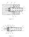
- Figure 3 is a cross section side view of an annular corrugated coaxial cable according to a second embodiment of the invention.
- Figure 4 is a cross section side view of the annular corrugated coaxial cable of figure 3, fitted with a connector, prior to axial compression.
- Figure 5 is a cross section side view of the annular corrugated coaxial cable of figure 3, fitted with a connector, prior to axial compression, showing axial compression tooling.
- Figure 6 is a cross section side view of the annular corrugated coaxial cable of figure 3, fitted with a connector, after axial compression.
-
- The present invention applies axial, rather than radial, mechanical compression forces to connector components to create a radial compression interconnection between a connector and the outer conductor of a coaxial cable.
- A first embodiment of the invention is shown in figures 1 and 2. A typical annular corrugated coaxial transmission line cable suitable for use with the invention is LDF4 manufactured by the assignee of the invention, Andrew Corporation of Orland Park, Illinois. The cable 1 has an outer conductor 3 with annular corrugations and an
inner conductor 5 surrounded bydielectric material 7. Prepared for axial compression, any outer protective sheath of the coaxial cable 1 is stripped back and the cable end 9 inserted through asleeve 11. Thesleeve 11 may be configured with asleeve bore 12 having a widersleeve cable end 13 diameter that transitions to asleeve connector end 15 diameter which extends to thesleeve connector end 15. Thesleeve cable end 13 diameter may be, for example, adapted to accept insertion of the cable 1 with the outer protective sheath in place. Thesleeve connector end 15 diameter is only slightly larger than the diameter of the outer conductor 3, allowing insertion of the outer conductor 3. The outer conductor 3 is flared after insertion through the sleeve, creating a flared end 17 which prevents removal of the cable 1 through thesleeve bore 12. - A
connector body 19 is configured to have a complementaryouter conductor seat 21 with an outer diameter which creates an interference fit between the thickness of the outer conductor 3 and thesleeve connector end 15 diameter. Preferably, a connector body bore 23 of theconnector body 19 has a diameter proximate the minimum diameter of the outer conductor 3 corrugations. Where theconnector body bore 23 is substantially equal to the outer conductor 3 corrugation bottom dimension, impedance discontinuities that my otherwise be generated by the presence of theconnector body 19 may be reduced. Other dimensions and features of the connector body (not shown) may be adapted by one skilled in the art to a desired connector end configuration, for example BNC, Type-N, DIN or other standardized or proprietary connector. - To complete a cable 1 and
connector body 19 interconnection, theconnector body 19 is axially compressed against the flared end 17 of the outer conductor 3 and thesleeve 11. As theouter conductor seat 21 presses against the flared end 17 and the flared end 17 against thesleeve connector end 15, the flared end 17 is drawn into acylindrical section 25 at the diameter of the outer conductor corrugation peaks that forms an interference fit between theconnector body 19, outer conductor 3 andsleeve 11 as shown in figure 2. The interference fit provides a secure, 360 degree void free contact between the outer conductor 3 and theconnector body 19 with excellent electrical properties. - For smaller dimensions of cable and corresponding connector bodies, a hand tool may be used to generate the required axial compression force. A hydraulic press or the like may be used for larger diameter cables having thicker outer conductors.
- In a second embodiment of the invention, axial compression is similarly applied but flaring and drawing of the outer conductor 3 into a
cylindrical section 25 is avoided by forming the coaxial cable 3 with extended cylindrical section(s) 25 at each corrugation peak. - As shown by the cable 1 used with the first embodiment (figures 1 and 2), the sinusoidal form of annular corrugations common in prior coaxial cables have a roughly equal dimension at the peak of the corrugations compared to the bottom corrugation dimension. As shown in figure 3, the cylindrical section(s) 25 of the novel cable 1 according to the invention have a length of at least four times that of the corresponding corrugation bottom, depending on the overall cable dimensions. Preferably, the cylindrical section is formed with a ten to one peak corrugation width to bottom corrugation width or at least a three millimeter corrugation peak
cylindrical section 25. - As the length of each
cylindrical section 25 is extended, the cable 1 begins to approximate the flexibility characteristics of a straight walled cable. However, at the preferred dimensions, the cable 1 according to the invention retains flexibility comparable to a conventional annular sinusoidally corrugated cable with similardielectric material 7. The reduction in the number of total corrugations resulting from the extended peak cylindrical section reduces the overall materials requirement for the outer conductor of the cable, reducing the materials cost of the cable, overall. - With the cable end 9 prepared by trimming just behind a corrugation to expose a
cylindrical section 25 for interconnection, a sleeve in the form of acrimp ring 27 is placed over the outer conductor 3 and anouter conductor seat 21 of aconnector body 19 is fitted into the cable end 9 against the inner surface of the outer conductor 3, as shown in figure 4. - The connector
body connector end 29 shown in figures 4-6 is adapted to a Type N connector configuration. Other connector end configurations, described hereinabove may also be used as desired. The cable 1 is trimmed so that an end of thecenter conductor 5 of the cable 1 extends beyond the outer conductor 3 and thedielectric material 5. Thecenter conductor 5 may be electrically connected, to acenter contact 31 of the connector, via spring fingers incorporated into thecenter contact 31. Thecenter contact 31 may be supported, coaxial with theconnector body 19 by, for example, an insulator 32 formed by an insert-molded polymer that is injected via aring groove 33 and one or more opening(s) 35 which connect thering groove 33 to the connector body bore 23. The molded polymer may be secured to the outer conductor and center contact by, for example, ridge(s) 37 on the inner surfaces of theconnector body 19 and outer surfaces of thecenter contact 31. - The
crimp ring 27 is a cylindrical ring designed to slip over the outer conductor 3 of the cable 1 prior to inserting the connector bodyouter conductor seat 21 into the end of the cable 1. To minimize thermal expansion differentials that may degrade the interconnection over time, thecrimp ring 27 is preferably formed from a material with good ductility and a similar thermal expansion coefficient to that of the material used for the outer conductor of the cable. Where the outer conductor 3 material is copper, the crimp ring material may be, for example, annealed copper. - As shown in figure 5, the
connector body 19 may be held in anest 39. Thecrimp ring 27 is contacted by the angled surfaces of two or more segmented dies 41. To allow removal after the compression force application, the segmented die(s) 41 may be adapted to nest within another carrier die 45. When thenest 39 and segmented die(s) 41 are placed over the connector and crimp ring, they are moved axially relative to each other whereby anangled die surface 43 deforms thecrimp ring 27 inward in a radial fashion. This causes thecrimp ring 27 to experience stresses beyond an elastic limit. It becomes permanently deformed as shown in figure 6, securing the connector body 16 to the outer conductor 3. - The axial movement of the dies during application of the compressive force allows a contiguous 360 degrees of radial contact upon the
crimp ring 27, simultaneously. Therefore, the deformation of thecrimp ring 27 is uniform. This creates a void free interconnection with high strength; very low and stable contact resistance, low inter-modulation distortion and a high level of interconnection reliability. - For systems or parts of systems where high cable flexibility is not a requirement, the connector according to the second embodiment may be used interchangeably with straight walled coaxial cable.
- The invention provides a cost effective connector and cable 1 interconnection with a minimum number of separate components, materials cost and required manufacturing operations. Further, the connector and cable 1 interconnection according to the invention has improved electrical and mechanical properties. The invention has been adapted for use with both standard annular corrugation cables and a novel cable optimized for the connector. Installation of the connector onto the cable in either embodiment may be achieved with a minimum of time and required assembly operations.
1 cable 3 outer conductor 5 inner conductor 7 dielectric material 9 cable end 11 sleeve 12 sleeve bore 13 sleeve cable end 15 sleeve connector end 17 flared end 19 connector body 21 outer conductor seat 23 connector body bore 25 cylindrical section 27 crimp ring 29 connector body connector end 31 center contact 33 ring groove 35 opening(s) 37 ridge(s) 39 nest 41 segmented die(s) 43 angled die surface 45 carrier die - Where in the foregoing description reference has been made to ratios, integers or components having known equivalents then such equivalents are herein incorporated as if individually set forth.
- While the present invention has been illustrated by the description of the embodiments thereof, and while the embodiments have been described in considerable detail, it is not the intention of the applicant to restrict or in any way limit the scope of the appended claims to such detail. Additional advantages and modifications will readily appear to those skilled in the art. Therefore, the invention in its broader aspects is not limited to the specific details, representative apparatus, methods, and illustrative examples shown and described. Accordingly, departures may be made from such details without departure from the spirit or scope of applicant's general inventive concept. Further, it is to be appreciated that improvements and/or modifications may be made thereto without departing from the scope or spirit of the present invention as defined by the following claims.
Claims (30)
- An electrical connector for a coaxial cable with a solid outer conductor having annular corrugations alternating between a corrugation peak diameter and a corrugation bottom diameter, comprising:a connector body with a cylindrical outer conductor seat; and a sleeve with a cylindrical sleeve bore;the outer conductor seat having an outer seat diameter adapted to be greater than the corrugation bottom diameter;the sleeve bore having a sleeve diameter greater than the corrugation peak diameter;the outer seat diameter and the sleeve diameter dimensioned to create an interference fit when the outer conductor seat is inserted into the outer conductor and into the sleeve bore, pressing the outer conductor between the outer conductor seat and the sleeve bore.
- The apparatus of claim 1, wherein the outer conductor annular corrugations are drawn into a cylindrical section as the outer conductor seat is inserted into the outer conductor and into the sleeve bore.
- The apparatus of claim 1, further including a transition to a larger diameter which extends to a cable end of the sleeve bore.
- The apparatus of claim 1, further including a connector body bore; the connector body bore coaxial with the sleeve bore and having an inner diameter substantially equal to the corrugation bottom diameter.
- A connector in combination with an annular corrugated coaxial cable having a solid outer conductor with annular corrugations, comprising:a connector body with an outer conductor seat; anda sleeve with a sleeve bore;an end portion of the outer conductor of the coaxial cable drawn into a cylindrical section and held by an interference fit between the outer conductor seat and the sleeve bore.
- The apparatus of claim 1, further including a connector body bore; the connector body bore coaxial with the sleeve bore and having an inner diameter substantially equal to a minimum diameter of the annular corrugations.
- A method for connecting a connector to a coaxial cable, comprising the steps of:inserting an outer conductor of the coaxial cable through a sleeve bore of a sleeve;flaring a cable end of the outer conductor;pressing an outer conductor seat against the cable end of the outer conductor and into the sleeve bore trapping the outer conductor between the outer conductor seat and the sleeve bore.
- The method of claim 7, wherein the outer conductor trapped between the outer conductor seat and the sleeve bore is drawn into a cylindrical section.
- The method of claim 7 wherein the pressing is performed with a hydraulic press operating along a longitudinal axis of the coaxial cable.
- An electrical connector for a coaxial cable with a solid outer conductor, comprising:a connector body with a cylindrical outer conductor seat; anda deformable crimp ring;the outer conductor seat and the crimp ring adapted to receive a cylindrical section of the solid outer conductor between them and to retain the cylindrical section upon application of a compression force applied along a longitudinal axis of the coaxial cable between the connector body and the crimp ring.
- The connector of claim 10, further including a connector body bore; the connector body bore coaxial with the outer conductor seat.
- The connector of claim 11, further including a center contact positioned coaxially within the connector body bore.
- The connector of claim 12, wherein the center contact retained by an insulator.
- The connector of claim 13, wherein the insulator is formed by injection molding injected through at least one opening formed in the connector body.
- The connector of claim 12, wherein the connector body and center contact are adapted to one of a BNC, Type N and DIN configuration.
- A connector in combination with a coaxial cable having a solid outer conductor, comprising:a connector body with an outer conductor seat; and a deformable crimp ring;an end portion of the outer conductor of the coaxial cable retained between the outer conductor seat and the deformable crimp ring.
- The combination of claim 16, wherein the solid outer conductor has annular corrugations; the annular corrugations having a cylindrical section at a peak of each corrugation.
- The combination of claim 16, wherein the cylindrical section has a length, along a longitudinal axis of the coaxial cable, at least four times a depth of the corrugations.
- The combination of claim 16, wherein the cylindrical section has a length, along a longitudinal axis of the coaxial cable, at least ten times a depth of the corrugations.
- The combination of claim 16, wherein the cylindrical section has a length, along a longitudinal axis of the coaxial cable, of at least 3 millimeters.
- The combination of claim 16, wherein the crimp ring and the solid outer conductor are formed from material(s) having a substantially equal thermal expansion coefficient.
- The combination of claim 16, further including a bore in the connector body coaxial with the outer conductor seat; and a center contact retained in the bore by an insulator.
- The combination of claim 22, wherein the insulator is an injection molded plastic; the plastic injected via at least one opening through the connector body to the bore.
- A method for attaching a connector body to a coaxial cable having a solid outer conductor, comprising the steps of:placing a crimp ring over an end the solid outer conductor;inserting a cylindrical section of the solid outer conductor over a conductor seat of the connector body;applying axial compression between the connector body and the crimp ring to deform the crimp ring over the cylindrical section of the solid outer conductor and the conductor seat, thereby retaining the cylindrical section between the crimp ring and the conductor seat.
- The method of claim 24, wherein the axial compression between the connector body and the crimp ring is applied upon a 360 degree periphery of the crimp ring.
- The method of claim 24, wherein the axial compression applied to the crimp ring is via a die surface angled towards the coaxial cable.
- The method of claim 24, wherein to apply the axial compression, the connector body is positioned in a nest; and a segmented die applied to the crimp ring is held by a host die.
- A coaxial cable, comprising:a cylindrical solid outer conductor surrounding an inner conductor isolated from the solid outer conductor by a dielectric;the solid outer conductor having annular corrugations with a cylindrical section at each corrugation peak;the cylindrical section having a length, along a longitudinal axis of the coaxial cable, at least ten times a depth of the corrugations.
- The cable of claim 28, wherein the cylindrical section has a length, along a longitudinal axis of the coaxial cable, of at least 3 millimeters.
- The cable of claim 28, wherein the solid outer conductor is one of copper and copper alloy.
Applications Claiming Priority (2)
| Application Number | Priority Date | Filing Date | Title |
|---|---|---|---|
| US10/707,853 US7044785B2 (en) | 2004-01-16 | 2004-01-16 | Connector and coaxial cable with outer conductor cylindrical section axial compression connection |
| US707853 | 2004-01-16 |
Publications (1)
| Publication Number | Publication Date |
|---|---|
| EP1555730A1 true EP1555730A1 (en) | 2005-07-20 |
Family
ID=34619842
Family Applications (1)
| Application Number | Title | Priority Date | Filing Date |
|---|---|---|---|
| EP04027657A Withdrawn EP1555730A1 (en) | 2004-01-16 | 2004-11-22 | Connector and coaxial cable with outer conductor cylindral section axial compression connection |
Country Status (6)
| Country | Link |
|---|---|
| US (2) | US7044785B2 (en) |
| EP (1) | EP1555730A1 (en) |
| KR (1) | KR20050075684A (en) |
| CN (1) | CN100474701C (en) |
| BR (1) | BRPI0500033A (en) |
| TW (1) | TW200525840A (en) |
Cited By (3)
| Publication number | Priority date | Publication date | Assignee | Title |
|---|---|---|---|---|
| US7189114B1 (en) | 2006-06-29 | 2007-03-13 | Corning Gilbert Inc. | Compression connector |
| EP3832811A1 (en) * | 2019-12-02 | 2021-06-09 | Corning Optical Communications ApS | Coaxial cable assemblies having pinching and gripping elements |
| CN114221159A (en) * | 2021-12-23 | 2022-03-22 | 杭州摩光通讯器材有限公司 | Connector for hollow cable |
Families Citing this family (55)
| Publication number | Priority date | Publication date | Assignee | Title |
|---|---|---|---|---|
| DE10350763A1 (en) * | 2002-11-16 | 2004-06-03 | Spinner Gmbh Elektrotechnische Fabrik | Formation of angle connector on end of flexible coaxial cable, comprises successively trimming away cable dielectric, outer conductor and cable jacket relative to respective inner conductor, cable dielectric and outer conductor |
| US7014501B2 (en) * | 2003-07-21 | 2006-03-21 | John Mezzalingua Associates, Inc. | Environmentally protected and tamper resistant CATV drop connector and method |
| US7261581B2 (en) * | 2003-12-01 | 2007-08-28 | Corning Gilbert Inc. | Coaxial connector and method |
| US6955562B1 (en) * | 2004-06-15 | 2005-10-18 | Corning Gilbert Inc. | Coaxial connector with center conductor seizure |
| NL1026698C2 (en) * | 2004-07-21 | 2006-01-30 | Framatome Connectors Int | Cable connector assembly with recoverable end of the shielding cover. |
| GB2417618B (en) * | 2004-08-31 | 2009-03-04 | Itt Mfg Enterprises Inc | Coaxial connector |
| US7077700B2 (en) * | 2004-12-20 | 2006-07-18 | Corning Gilbert Inc. | Coaxial connector with back nut clamping ring |
| US7354307B2 (en) * | 2005-06-27 | 2008-04-08 | Pro Brand International, Inc. | End connector for coaxial cable |
| US7425676B2 (en) * | 2005-09-08 | 2008-09-16 | At&T Intellectual Property L.L.P. | Coaxial cable for exterior use |
| US7217154B2 (en) * | 2005-10-19 | 2007-05-15 | Andrew Corporation | Connector with outer conductor axial compression connection and method of manufacture |
| US7232955B1 (en) | 2005-12-08 | 2007-06-19 | General Electric Company | Cable seals and methods of assembly |
| EP1999821A4 (en) * | 2006-03-29 | 2011-03-16 | Corning Gilbert Inc | Coaxial connector and coaxial cable connector assembly and related method |
| US7371112B2 (en) * | 2006-08-04 | 2008-05-13 | Corning Gilbert Inc. | Coaxial connector and coaxial cable connector assembly and related method |
| US7311554B1 (en) | 2006-08-17 | 2007-12-25 | John Mezzalingua Associates, Inc. | Compact compression connector with flexible clamp for corrugated coaxial cable |
| US7351101B1 (en) | 2006-08-17 | 2008-04-01 | John Mezzalingua Associates, Inc. | Compact compression connector for annular corrugated coaxial cable |
| US7458851B2 (en) * | 2007-02-22 | 2008-12-02 | John Mezzalingua Associates, Inc. | Coaxial cable connector with independently actuated engagement of inner and outer conductors |
| US7458850B1 (en) | 2007-05-23 | 2008-12-02 | Corning Gilbert Inc. | Right-angled coaxial cable connector |
| US7892267B2 (en) * | 2007-08-03 | 2011-02-22 | Zimmer Spine, Inc. | Attachment devices and methods for spinal implants |
| CN101540461A (en) * | 2008-03-17 | 2009-09-23 | 北卡罗来纳康姆斯科普公司 | Coaxial cable crimp connector |
| DE202008015000U1 (en) * | 2008-11-12 | 2009-01-29 | Rosenberger Hochfrequenztechnik Gmbh & Co. Kg | RF connectors |
| US8282138B2 (en) * | 2008-12-18 | 2012-10-09 | Rostra Tool Company | Crimp ring |
| KR101140233B1 (en) * | 2009-02-24 | 2012-04-26 | 엘에스전선 주식회사 | Coaxial cable |
| DE102009001850A1 (en) * | 2009-03-25 | 2010-09-30 | Robert Bosch Gmbh | Electrical connection of paired conductor ends and method of making the connection |
| US7931498B2 (en) * | 2009-04-08 | 2011-04-26 | John Mezzalingua Associates, Inc. | Coaxial cable connector with a deformable compression cap to form a constriction |
| US8468688B2 (en) | 2010-04-02 | 2013-06-25 | John Mezzalingua Associates, LLC | Coaxial cable preparation tools |
| US7934954B1 (en) | 2010-04-02 | 2011-05-03 | John Mezzalingua Associates, Inc. | Coaxial cable compression connectors |
| US9166306B2 (en) | 2010-04-02 | 2015-10-20 | John Mezzalingua Associates, LLC | Method of terminating a coaxial cable |
| US8177582B2 (en) | 2010-04-02 | 2012-05-15 | John Mezzalingua Associates, Inc. | Impedance management in coaxial cable terminations |
| DE102010045780A1 (en) * | 2010-09-17 | 2012-03-22 | Rohde & Schwarz Gmbh & Co. Kg | Calibration unit for a measuring device |
| US8365404B2 (en) | 2010-11-22 | 2013-02-05 | Andrew Llc | Method for ultrasonic welding a coaxial cable to a coaxial connector |
| US8887388B2 (en) | 2010-11-22 | 2014-11-18 | Andrew Llc | Method for interconnecting a coaxial connector with a solid outer conductor coaxial cable |
| US9728926B2 (en) | 2010-11-22 | 2017-08-08 | Commscope Technologies Llc | Method and apparatus for radial ultrasonic welding interconnected coaxial connector |
| US8876549B2 (en) | 2010-11-22 | 2014-11-04 | Andrew Llc | Capacitively coupled flat conductor connector |
| US8302296B2 (en) | 2010-11-22 | 2012-11-06 | Andrew, Llc | Friction weld coaxial connector and interconnection method |
| US8479383B2 (en) | 2010-11-22 | 2013-07-09 | Andrew Llc | Friction weld coaxial connector and interconnection method |
| US8453320B2 (en) | 2010-11-22 | 2013-06-04 | Andrew Llc | Method of interconnecting a coaxial connector to a coaxial cable via ultrasonic welding |
| US9761959B2 (en) | 2010-11-22 | 2017-09-12 | Commscope Technologies Llc | Ultrasonic weld coaxial connector |
| US8563861B2 (en) | 2010-11-22 | 2013-10-22 | Andrew Llc | Friction weld inner conductor cap and interconnection method |
| US8826525B2 (en) | 2010-11-22 | 2014-09-09 | Andrew Llc | Laser weld coaxial connector and interconnection method |
| US9024191B2 (en) * | 2011-10-03 | 2015-05-05 | Commscope Technologies Llc | Strain relief for connector and cable interconnection |
| WO2013089160A1 (en) * | 2011-12-13 | 2013-06-20 | 矢崎総業株式会社 | Structure for fixing electrical connection section, connector, and method for connecting connector |
| US9017102B2 (en) * | 2012-02-06 | 2015-04-28 | John Mezzalingua Associates, LLC | Port assembly connector for engaging a coaxial cable and an outer conductor |
| US9171659B2 (en) * | 2012-09-14 | 2015-10-27 | Abb Research Ltd | Radial water barrier and a dynamic high voltage submarine cable for deep water applications |
| WO2014059365A1 (en) * | 2012-10-11 | 2014-04-17 | John Mezzalingua Associates, LLC | Coaxial cable device and method involving weld connectivity |
| US9312609B2 (en) * | 2012-10-11 | 2016-04-12 | John Mezzalingua Associates, LLC | Coaxial cable device and method involving weld and mate connectivity |
| US9633765B2 (en) | 2012-10-11 | 2017-04-25 | John Mezzalingua Associates, LLC | Coaxial cable device having a helical outer conductor and method for effecting weld connectivity |
| US9633761B2 (en) | 2014-11-25 | 2017-04-25 | John Mezzalingua Associates, LLC | Center conductor tip |
| US20170133130A1 (en) * | 2015-11-05 | 2017-05-11 | Commscope Technologies Llc | Coaxial cable with thin corrugated outer conductor and method of forming same |
| CN105322409B (en) * | 2015-11-16 | 2018-08-24 | 陕西航空电气有限责任公司 | A kind of housing component cold extrusion connection method and housing component |
| CN106981795B (en) * | 2016-01-15 | 2020-07-31 | 康普技术有限责任公司 | Cable-connector assembly with heat shrinkable sleeve |
| JP6330845B2 (en) * | 2016-04-19 | 2018-05-30 | Smk株式会社 | Wire connector |
| JP2019129104A (en) * | 2018-01-26 | 2019-08-01 | 日立金属株式会社 | Insulated electrical wire |
| DE102018127578A1 (en) * | 2018-11-06 | 2020-05-07 | Rosenberger Hochfrequenztechnik Gmbh & Co. Kg | CABLE ARRANGEMENT |
| US11936134B2 (en) | 2021-01-08 | 2024-03-19 | Corning Optical Communications Rf Llc | Coaxial connector assembly having locking ferrule |
| CN114334267B (en) * | 2021-12-28 | 2024-02-06 | 山西交投产业科技发展有限公司 | Cable capable of preventing axial pressurization |
Citations (8)
| Publication number | Priority date | Publication date | Assignee | Title |
|---|---|---|---|---|
| GB650429A (en) * | 1946-09-04 | 1951-02-21 | Standard Telephones Cables Ltd | Improvements in or relating to electric cables for high frequency |
| DE900364C (en) * | 1943-07-19 | 1953-12-21 | Comp Generale Electricite | Concentric cable with a composite outer conductor |
| US3701086A (en) * | 1971-05-28 | 1972-10-24 | Itt | Coaxial connector |
| GB1421215A (en) * | 1972-05-04 | 1976-01-14 | ||
| US4813887A (en) * | 1986-09-05 | 1989-03-21 | Amp Incorporated | Electrical connector for multiple outer conductor coaxial cable |
| US5166477A (en) * | 1991-05-28 | 1992-11-24 | General Electric Company | Cable and termination for high voltage and high frequency applications |
| EP0517034A2 (en) * | 1991-06-04 | 1992-12-09 | Andrew A.G. | Connector for coaxial cable having a helically corrugated inner conductor |
| DE29800824U1 (en) * | 1998-01-19 | 1998-03-12 | Huber+Suhner Ag | Connector on a coaxial cable with a screwed corrugated outer conductor |
Family Cites Families (25)
| Publication number | Priority date | Publication date | Assignee | Title |
|---|---|---|---|---|
| US2870792A (en) | 1956-03-07 | 1959-01-27 | Pirelli General Cable Works | Metal tubes or metal sheaths of electric cables |
| US3582536A (en) | 1969-04-28 | 1971-06-01 | Andrew Corp | Corrugated coaxial cable |
| US3754094A (en) | 1971-01-25 | 1973-08-21 | Kabel Metallwerke Ghh | Cable with welded corrugated metal sheath |
| US4368350A (en) | 1980-02-29 | 1983-01-11 | Andrew Corporation | Corrugated coaxial cable |
| US4376229A (en) | 1980-09-16 | 1983-03-08 | Raychem Corporation | Shielded conduit |
| US4453796A (en) * | 1982-06-21 | 1984-06-12 | Amp Incorporated | Coaxial connector plug |
| US4774839A (en) * | 1982-12-27 | 1988-10-04 | American National Can Company | Method and apparatus for necking containers |
| US5120260A (en) * | 1983-08-22 | 1992-06-09 | Kings Electronics Co., Inc. | Connector for semi-rigid coaxial cable |
| DE3522736C1 (en) | 1985-06-25 | 1987-02-19 | Spinner Gmbh Elektrotech | Device for the pressure-tight connection of the outer conductor of a coaxial line |
| JPH0341434Y2 (en) * | 1986-09-17 | 1991-08-30 | ||
| US5137471A (en) * | 1990-07-06 | 1992-08-11 | Amphenol Corporation | Modular plug connector and method of assembly |
| US5154636A (en) | 1991-01-15 | 1992-10-13 | Andrew Corporation | Self-flaring connector for coaxial cable having a helically corrugated outer conductor |
| US5295864A (en) | 1993-04-06 | 1994-03-22 | The Whitaker Corporation | Sealed coaxial connector |
| US5284449A (en) | 1993-05-13 | 1994-02-08 | Amphenol Corporation | Connector for a conduit with an annularly corrugated outer casing |
| US5354217A (en) * | 1993-06-10 | 1994-10-11 | Andrew Corporation | Lightweight connector for a coaxial cable |
| JP2916665B2 (en) * | 1994-06-28 | 1999-07-05 | 三菱電線工業株式会社 | connector |
| US5795188A (en) * | 1996-03-28 | 1998-08-18 | Andrew Corporation | Connector kit for a coaxial cable, method of attachment and the resulting assembly |
| US5760334A (en) | 1996-07-24 | 1998-06-02 | Alcatel Kabel Ag & Co. | Metallic sheath for an electric cable and method of making the same |
| DE19729876C2 (en) * | 1997-07-11 | 1999-11-11 | Spinner Gmbh Elektrotech | Connectors for coaxial cables |
| US6153830A (en) * | 1997-08-02 | 2000-11-28 | John Mezzalingua Associates, Inc. | Connector and method of operation |
| DE50008711D1 (en) * | 1999-02-10 | 2004-12-30 | Spinner Gmbh Elektrotech | Connector for coaxial cable with smooth outer conductor |
| DE10055992C2 (en) * | 2000-04-07 | 2003-07-10 | Spinner Gmbh Elektrotech | Solderable coaxial connector |
| US6386915B1 (en) | 2000-11-14 | 2002-05-14 | Radio Frequency Systems, Inc. | One step connector |
| JP4801274B2 (en) * | 2001-03-29 | 2011-10-26 | 本田技研工業株式会社 | Control box with built-in pressure sensor |
| CN100548613C (en) * | 2002-01-09 | 2009-10-14 | 托马斯及贝茨国际股份有限公司 | Be used to protect the coated semiconductor and the application process of elastomeric electrical cable accessories |
-
2004
- 2004-01-16 US US10/707,853 patent/US7044785B2/en not_active Expired - Fee Related
- 2004-11-08 US US10/904,398 patent/US20050159044A1/en not_active Abandoned
- 2004-11-11 KR KR1020040091777A patent/KR20050075684A/en not_active Application Discontinuation
- 2004-11-22 EP EP04027657A patent/EP1555730A1/en not_active Withdrawn
- 2004-12-01 CN CNB2004100980167A patent/CN100474701C/en not_active Expired - Fee Related
- 2004-12-20 TW TW093139580A patent/TW200525840A/en unknown
-
2005
- 2005-01-07 BR BR0500033-5A patent/BRPI0500033A/en not_active IP Right Cessation
Patent Citations (8)
| Publication number | Priority date | Publication date | Assignee | Title |
|---|---|---|---|---|
| DE900364C (en) * | 1943-07-19 | 1953-12-21 | Comp Generale Electricite | Concentric cable with a composite outer conductor |
| GB650429A (en) * | 1946-09-04 | 1951-02-21 | Standard Telephones Cables Ltd | Improvements in or relating to electric cables for high frequency |
| US3701086A (en) * | 1971-05-28 | 1972-10-24 | Itt | Coaxial connector |
| GB1421215A (en) * | 1972-05-04 | 1976-01-14 | ||
| US4813887A (en) * | 1986-09-05 | 1989-03-21 | Amp Incorporated | Electrical connector for multiple outer conductor coaxial cable |
| US5166477A (en) * | 1991-05-28 | 1992-11-24 | General Electric Company | Cable and termination for high voltage and high frequency applications |
| EP0517034A2 (en) * | 1991-06-04 | 1992-12-09 | Andrew A.G. | Connector for coaxial cable having a helically corrugated inner conductor |
| DE29800824U1 (en) * | 1998-01-19 | 1998-03-12 | Huber+Suhner Ag | Connector on a coaxial cable with a screwed corrugated outer conductor |
Cited By (4)
| Publication number | Priority date | Publication date | Assignee | Title |
|---|---|---|---|---|
| US7189114B1 (en) | 2006-06-29 | 2007-03-13 | Corning Gilbert Inc. | Compression connector |
| EP3832811A1 (en) * | 2019-12-02 | 2021-06-09 | Corning Optical Communications ApS | Coaxial cable assemblies having pinching and gripping elements |
| CN114221159A (en) * | 2021-12-23 | 2022-03-22 | 杭州摩光通讯器材有限公司 | Connector for hollow cable |
| CN114221159B (en) * | 2021-12-23 | 2023-08-29 | 杭州摩光通讯器材有限公司 | Connector for hollow cable |
Also Published As
| Publication number | Publication date |
|---|---|
| TW200525840A (en) | 2005-08-01 |
| US20050159043A1 (en) | 2005-07-21 |
| CN1641936A (en) | 2005-07-20 |
| BRPI0500033A (en) | 2005-08-23 |
| KR20050075684A (en) | 2005-07-21 |
| CN100474701C (en) | 2009-04-01 |
| US20050159044A1 (en) | 2005-07-21 |
| US7044785B2 (en) | 2006-05-16 |
Similar Documents
| Publication | Publication Date | Title |
|---|---|---|
| US7044785B2 (en) | Connector and coaxial cable with outer conductor cylindrical section axial compression connection | |
| US7854063B2 (en) | Method of manufacture a connector with outer conductor axial compression connection | |
| US8007314B2 (en) | Compression connector for coaxial cable | |
| US7371112B2 (en) | Coaxial connector and coaxial cable connector assembly and related method | |
| US8177583B2 (en) | Compression connector for coaxial cable | |
| US7993159B2 (en) | Compression connector for coaxial cable | |
| US7275957B1 (en) | Axial compression electrical connector for annular corrugated coaxial cable | |
| US20130267109A1 (en) | Coaxial Cable Connector with Strain Relief Clamp | |
| WO2007126711A1 (en) | Coaxial connector and coaxial cable connector assembly and related method | |
| WO2007078945A2 (en) | Coaxial cable connector with clamping insert | |
| US9748711B2 (en) | HF coaxial cable with angular plug connection, and a method for producing same | |
| US6250963B1 (en) | Connector shell, connector assembly and method of fabricating same | |
| WO2011163268A2 (en) | Strain relief accessory for coaxial cable connector | |
| CA1239677A (en) | Method for joining two aluminum conductors of electric cables and the joint thus obtained | |
| US20230387614A1 (en) | Nut seal assembly for coaxial cable system components that provides a mechanically secure waterproof seal | |
| CN219350697U (en) | Connecting terminal, electric connection structure and copper-aluminum connector | |
| JP2681430B2 (en) | Electric cable connection structure |
Legal Events
| Date | Code | Title | Description |
|---|---|---|---|
| PUAI | Public reference made under article 153(3) epc to a published international application that has entered the european phase |
Free format text: ORIGINAL CODE: 0009012 |
|
| AK | Designated contracting states |
Kind code of ref document: A1 Designated state(s): AT BE BG CH CY CZ DE DK EE ES FI FR GB GR HU IE IS IT LI LU MC NL PL PT RO SE SI SK TR |
|
| AX | Request for extension of the european patent |
Extension state: AL HR LT LV MK YU |
|
| 17P | Request for examination filed |
Effective date: 20051209 |
|
| AKX | Designation fees paid |
Designated state(s): AT BE BG CH CY CZ DE DK EE ES FI FR GB GR HU IE IS IT LI LU MC NL PL PT RO SE SI SK TR |
|
| STAA | Information on the status of an ep patent application or granted ep patent |
Free format text: STATUS: THE APPLICATION IS DEEMED TO BE WITHDRAWN |
|
| 18D | Application deemed to be withdrawn |
Effective date: 20110601 |