EP1555342B1 - A laundry dryer and an air inlet structure thereof - Google Patents
A laundry dryer and an air inlet structure thereof Download PDFInfo
- Publication number
- EP1555342B1 EP1555342B1 EP04293021.4A EP04293021A EP1555342B1 EP 1555342 B1 EP1555342 B1 EP 1555342B1 EP 04293021 A EP04293021 A EP 04293021A EP 1555342 B1 EP1555342 B1 EP 1555342B1
- Authority
- EP
- European Patent Office
- Prior art keywords
- base
- air
- cover
- guide
- blower
- Prior art date
- Legal status (The legal status is an assumption and is not a legal conclusion. Google has not performed a legal analysis and makes no representation as to the accuracy of the status listed.)
- Not-in-force
Links
Images


Classifications
-
- D—TEXTILES; PAPER
- D06—TREATMENT OF TEXTILES OR THE LIKE; LAUNDERING; FLEXIBLE MATERIALS NOT OTHERWISE PROVIDED FOR
- D06F—LAUNDERING, DRYING, IRONING, PRESSING OR FOLDING TEXTILE ARTICLES
- D06F58/00—Domestic laundry dryers
- D06F58/02—Domestic laundry dryers having dryer drums rotating about a horizontal axis
- D06F58/04—Details
Definitions
- the present invention relates to a laundry dryer and an air inlet structure thereof, and more particularly, to an air inlet structure of a laundry dryer, in which an ambient air is smoothly sucked into a condenser for a heat exchange with a high-temperature/damp circulation air, and then smoothly discharged from the dryer.
- a drum-type laundry dryer is a home appliance, in which a heat source such as an electric heater and a gas combustion device is used to heat air and the heated air is blown into a drum to evaporate the remaining moisture in laundry.
- a heat source such as an electric heater and a gas combustion device is used to heat air and the heated air is blown into a drum to evaporate the remaining moisture in laundry.
- the drum-type laundry dryer may be classified into a condenser-type dryer and an exhaust-type dryer.
- the former is designed such that the air in the dryer is used to dry the laundry as it is circulated in the dryer.
- the latter is designed such that air introduced in the dryer is used to dry the laundry and then the air is discharged from the dryer.
- the exhaust-type laundry dryer may also be classified into a gas-type dryer and an electric-type dryer, according to the type of heater that heats the introduced air.
- a heat includes a furnace in which a fuel gas burns, an igniter, and a flame sensor, such that the air introduced in the dryer can be heated by the heat generated at the furnace.
- the electric-type dryer uses an electric heater that has a heating coil to heat the air introduced in the dryer, such that the laundry can be dried by the electrically heated air.
- the condenser-type laundry dryer includes a front cover, a suction hole defined at a lower portion of the front cover to pass ambient air therethrough, a base disposed inside the suction hole, a condenser mounted in the base, and a fan inside the suction hole.
- the base defines an air inlet that is connected with the suction hole, an air passage, such that ambient air can be introduced through the suction hole and the air inlet, for exchanging heat with circulation air in the dryer.
- the condenser-type dryer requires a structure that can introduce the ambient air from the suction hole to the fan in a smooth and efficient manner.
- the condenser-type dryer requires a structure that can minimize fluid loss and noise that are caused by fluid friction during the introduction of the ambient air into the dryer.
- the present invention is directed to a laundry dryer and air inlet structure thereof that substantially obviates one or more problems due to limitations and disadvantages of the related art.
- An object of the present invention is to provide a laundry dryer and air inlet structure thereof, in which the noise caused by collision between sucking ambient air and a surface of a base can be reduced, and the loss caused by flow friction can be reduced.
- Another object of the present invention is to provide a laundry dryer and air inlet structure thereof, in which an air inlet structure is improved such that the suction efficiency of a fan can be increased.
- the noise caused by collision between sucking ambient air and a surface of a base can be reduced, and the loss caused by flow friction can be reduced.
- the air inlet structure is improved such that the suction efficiency of a fan can be increased.
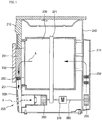
- Fig. 1 is a sectional view of a condenser-type laundry dryer according to the present invention.
- a condenser-type laundry dryer 200 includes an outer case 210, a front cabinet 500 installed at a front of the outer case 210, a cylindrical drum 220 mounted in the outer case 210 to receive the laundry therein, a door 230 controlling the opening of the drum 220, and a belt 221 disposed around an outer circumference of the drum 220 to rotate the drum 220.
- the front cabinet 500 defines a hole for passing air therethrough.
- the condenser-type laundry dryer 200 further includes a motor shaft 280 connected to the belt 221 to transmit rotational force to the drum 220, a motor 270 for transmitting the rotational force to the motor shaft 280, and a cooling fan 260 connected to a first end of the motor shaft 280 to rotate by receiving the rotational force of the motor 270 and intake ambient air.
- the laundry dryer 200 further includes a dry fan 295 connected to a second end of the motor shaft 280 to circulate air in the drum 220 and a duct cover 211 connecting the dry fan 295 to the drum 220 to allow the air introduced by the dry fan 295 to be directed to the drum 220.
- the cooling fan 260 and the dry fan 295 are disposed facing each other and the motor 270 is disposed between the cooling and dry fan 260 and 295.
- the dry fan 295 and a heater 290 are received in the duct cover 211 defining an air passage through which the circulation air introduced by the dry fan 295 is directed to a back of the drum 220.
- the dryer 200 includes a door lint filter 231 disposed on a rear surface of the door 230 for primarily filtering foreign objects contained in the circulation air and a body lint filter 250 disposed under the door lint filter for secondary filtering foreign objects contained in the circulation air passed through the door lint filter 231.
- a circulation duct 251 along which the circulation air passed through the body lint duct 250 is directed to a condenser (refer to 190 in Fig. 2 ).
- the motor 270 rotates and the heater 290 mounted in the duct cover 211 is excited. Then, the belt 221 connected to the motor shaft 280 rotates to rotate the drum 220. As the drum 220 rotates, the laundry in the drum 220 is lifted and dropped by the lift (not shown) mounted on the inner wall of the drum 220.
- the dry fan 295 connected to the motor shaft 280 rotates by the rotation of the motor 270 to introduce the circulation air via the condenser.
- the air flows upward along the duct cover 211 and passes through the heater 290 to be converted into high-temperature/dry air. Then, the air is directed into the drum 220 to absorb the moisture contained in the laundry, thereby being converted into the high-temperature/damp air.
- the high-temperature/damp air is directed to the condenser 190 along the circulation duct 251 after passing through the door lint filter 231 and the body lint filter 250.
- the condenser 190 is designed such that the high-temperature/damp air and the ambient air are not mixed with each other but heat-exchanged.
- the high-temperature/damp air gives heat to the ambient air as it goes through the condenser, thereby being changed into low-temperature/damp air, in the course of which the moisture contained in the low-temperature/damp air is condensed.
- the condensed moisture is dropt on the floor of the condenser 190 and is then directed to a condensed water collector (refer to 150 in Fig. 2 )
- the moisture directed to the condensed water collector 150 is transmitted to a condensed water storage 212 disposed on an upper portion of the dryer 200. Meanwhile, the ambient air passing trough the condenser takes the heat from the high-temperature/damp air to change the circulation air into the lower-temperature/damp air. As a result, the temperature of the ambient air is increased.
- the circulation air introduced by the dry fan 295 flows along the passage defined by the duct cover 211. Then, as it passes through the heater 290, it is changed into the high-temperature/dry air and is then directed into the drum 220.
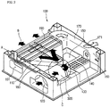
- Fig. 2 is a perspective view of a base with an ambient air inlet structure according to the present invention.
- a base 100 includes an air descending part 110, a condenser insertion hole 191, a condenser 190, and a circulation air passage 170.
- the circulation air enters the base 100 through the air descending part 110 after passing the drum 220 and the door lint filter 231.
- the condenser insertion hole 191 is defined at a bottom front portion of the air descending part 110.
- the condenser 190 is inserted though the condenser insertion hole 191 into the base 100.
- the circulation air passage 170 provides a passage for the circulation air passed the condenser 190.
- the base 100 includes an air inlet 120, a fan mounting space 130, a blower tube 300, and air guide 180.
- the air inlet 120 is defined at a front right of the base 100 to pass ambient air therethrough.
- the fan mounting space 130 is a place where the cooling fan 260 is mounted.
- the blower tube 300 provides a passage for the ambient air from the air inlet 120 to the cooling fan 260.
- the air guide 180 is formed from the fan mounting space 130 to the condenser 190 with an increasing width. Since the cooling fan 260 is a cross flow fan that sucks air in an axial direction and discharges the air in a radial direction, the blower tube 300 and the air guide 180 are connected at a predetermined angle.
- the base 100 includes the motor 270 disposed behind the fan mounting space 130 to rotate the drum 220, heat release holes 140 for passing an air heated by the operation of the motor 270, a shaft hole 160 formed at an end of the circulation air passage 170 for inserting the motor shaft, a condensed water collector 150 formed at about center to collect condensed water dropping from the condenser 190.
- the circulation air which has been heated and damped during passing through the heater 290 and the drum 220, enters the air descending part 110 from the door lint filter 231 and body lint filter 250 and passes through the condenser 190.
- Ambient air is introduced through the air inlet 120 and is blown to the condenser 190 by the cooling fan 260.
- the ambient air takes heat from the high-temperature circulation air.
- the condenser 190 is designed in a cross structure such that the ambient air and circulation air can exchange heat each other without mixing.
- the circulation air passed the condenser 190 moves back to the drum along the circulation air passage 170 and duct cover 211.
- the ambient air passed the condenser is discharged out of the laundry dryer 200.
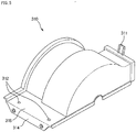
- Fig. 3 is an enlarged partial perspective view of a base with an ambient air inlet structure according to the present invention
- Fig. 4 is an enlarged view of a circular portion "C" depicted in Fig. 2 .
- the base includes a blower tube cover 310 mounted at an exit end of the blower tube 300 to cover the cooling fan 260.
- the blower tube 300 defines a guide holding groove 330 at an inside of its exit end to hold an air guide (refer to 400 in Fig. 7 ).
- the air guide 400 guides the ambient air to the cooling fan 260.
- the guide holding groove 330 is defined between two ribs 330a that are protruded from the base 100 with predetermined heights and widths.
- the ribs 330a is designed such that the air guide 400 can be inserted into the guide holding groove 330 exactly and tightly.
- the fan mounting space 130 is defined behind the guide holding groove 330.
- a tab keeper 340 is formed at an upper surface of the base 100 to fix the blower cover 310.
- the tab keeper 340 is protruded upwardly from the upper surface of the base 100 with a predetermined height and of which end is bent downwardly, such that a cover fixing tab, formed at a side end of the blower cover 310 with a corresponding width (refer to 311 in Fig. 5 ), can be inserted to the tab keeper 340.
- the base 100 includes guide protrusion pockets 350 at an upper surface opposing to the tab keeper 340 to receive guide protrusions (refer to 313 in Fig. 5 )
- cover anchoring holes 360 are defined between the guide protrusion pockets 350 to fix the blower cover 310 to the base 100.
- Fig. 5 is a perspective view showing an outside of a blower cover according to the present invention
- Fig. 6 is a perspective view showing an inside of a blower cover according to the present invention.
- the blower cover 310 which is to be mounted on the base 100 to form a passage for the introduced ambient air, has a semi-cylindrical shape to cover the cooling fan 260.
- the blower cover 310 includes the cover fixing tab 311 projected upwardly with a predetermined height from an end portion, for mounting on the base 100.
- the blower cover 310 includes an extended portion 318 at a side end opposing to the cover fixing tab 311, for mounting on the base 100.
- the extended portion 318 is bent from the side end and extended by a predetermined length.
- the extended portion 318 includes cover fixing holes 312, in which coupling members are to be inserted for fixing the blower cover 310 on the base 100.
- the blower cover 310 includes a bent portion 314 that is extended from an end of the extended portion 318 in a downward direction.
- the bent portion 314 guides the mounting of the blower cover 310 on the base 100 and prevents the blower cover 310 from lateral movement after the mounting.
- the base 100 may define a recessed portion (not shown) having shape and depth corresponding to the bent portion 314 to receive the bent portion 314 exactly.
- the blower cover 310 includes a sealing member 317 attached along its inner edge to be faced with the blower tube 300 in order to prevent the ambient air from leakage. Also, the blower cover 310 defines a guide inserting groove 316 at its inner surface to fix the air guide 400 exactly in the blower cover 310.
- the blower cover 310 includes ribs 316a having predetermined heights and gap therebetween to define the guide inserting groove 316 therebetween.
- the ribs 316a have the same radius of curvature as the air guide 400.
- the guide inserting groove 316 prevents the air guide 400 from forward and backward movements by the ambient air sucked through the blower tube 300.
- blower cover 310 includes a shaft receiving hole 315 to insert the motor shaft 280 to drive the cooling fan 260 with the motor 270.
- the shape of the shaft receiving hole 315 is semi-circular to face an upper portion of the motor shaft 280.
- Another shaft receiving hole 141 with a semi-circular shape is formed at the base 100 (refer to Fig 4 ) to face a lower portion of the motor shaft 280. Therefore, the shaft receiving hole 315 and shaft receiving hole 141 are facing each other to define a circular hole when the blower cover 310 is mounted on the base.
- blower cover 310 includes the guide protrusions 313 at a bottom side of the extended portion 318.
- the guide protrusions 313 arc protruded downwardly with predetermined lengths to exactly align the cover fixing holes 312 with the cover anchoring holes 360 of the base 100.
- the guide protrusions 313 guide the mounting of the blower cover 310 on the base 100, and as well prevent the blower cover 310 from movement on the base 100 when the blower cover 310 is mounted on the base 100.
- the blower cover 310 is placed above the base 100 with facing its shaft receiving hole 315 with the shaft receiving hole 141 of the base, and the cover fixing tab 311 is inserted into the tab keeper 340. Then, the guide protrusions 313 are inserted into the guide protrusion pockets 350 to abut the extended portion 318 on the upper surface of the base 100. Then, coupling members are inserted into the cover fixing holes 312 and the cover anchoring holes 360 to securely fix the blower cover 310 to the base 100.
- the air guide 400 is erected on the base 100 by inserting it on the guide holding groove 330 of the base 100 prior to mounting the blower cover 310 on the base 100, such that the erected air guide 400 can be inserted into the guide inserting groove 316 when the extended portion 318 is abutted on the upper surface of the base 100.
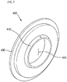
- Fig. 7 is a perspective view of an air guide according to the present invention.
- the outer diameter of the air guide 400 is the same as the inner diameter of the blower tube 300.
- the air guide 400 includes a shroud 410 at a center portion and an air passage hole 420 defined in the shroud 410 to pass the ambient air therethrough.
- the shroud 410 is bent toward the cooling fan 260 to guide the ambient air sucked through the air inlet 120 toward the cooling fan 260.
- the bent portion of the shroud 410 is smoothly rounded to have a predetermined radius of curvature in order to minimize flow friction.
- the air guide 400 reduces the presser of the ambient air flowing therethrough but increases the velocity of the ambient air, thereby increasing the velocity of the ambient air after it passed the cooling fan 260.
- the air guide 400 includes a flange 430 along its circumference.
- the width flange 430 is the same as the widths of the guide holding groove 330 and guide inserting groove 316, and the height of the flange 430 is the same as the depths of the guide holding groove 330 and guide inserting groove 316, such that the flange 430 can be tightly inserted into the guide holding groove 330 and guide inserting groove 316.
- the flange 430 is inserted into the guide holding groove 330, and then the blower cover 310 of which inner barrier rib 33 is hinged to the tab keeper 340 is rotated down to the base 100, such that the guide inserting groove 316 defined inside the blower cover 310 can be coupled with the air guide 400.
- the guide holding groove 330 coupled with the air guide 400 make the air guide 400 stand, it is not required to hold the air guide 400 by the hand when the blower cover 310 is mounted on the base 100.
- Fig. 8 is a partial front view of a laundry dryer with an air inlet structure according to the present invention
- Fig. 9 is a sectional view taken on I-I' line in Fig. 8
- Fig. 10 is a sectional view taken on II-II' line in Fig. 8.
- the front cabinet 500 forms the front external appearance of the laundry dryer 200.
- the door 230 is attached to the front cabinet 500.
- the condenser insertion hole 191 is defined under the door 230 to insert the condenser 190.
- the front cabinet 500 includes a suction hole 522 under the condenser insertion hole 191 to pass the ambient air and a suction grill 520 to cover grill hole 521 in order to guide the suction of the ambient air.
- the number of the suction grill 520 may be at least one, and holes are defined among bars of the suction grill 520.
- the suction hole 521 is defined in front of the base 100 to communicate with the air inlet 120.
- the bars of the suction grill 520 may be designed to point downward at a predetermined angle in order to reduce suction of foreign substances of the ambient air.
- the air blocking part 522 is provided to prevent noise that may be produced when the ambient air is sucked through the portion of the suction grill 520 and collided with front surface of the base 100 where the air inlet 120 is not defined.
- the holes of the suction grill 520 are defined only in front of the air inlet 120 of the base 100, such that the ambient air can be sucked in a straight line toward the cooling fan 260, and the noise produced by the collision between the ambient air and the front surface of the base can be prevented.
Description
- The present invention relates to a laundry dryer and an air inlet structure thereof, and more particularly, to an air inlet structure of a laundry dryer, in which an ambient air is smoothly sucked into a condenser for a heat exchange with a high-temperature/damp circulation air, and then smoothly discharged from the dryer.
- Generally, a drum-type laundry dryer is a home appliance, in which a heat source such as an electric heater and a gas combustion device is used to heat air and the heated air is blown into a drum to evaporate the remaining moisture in laundry.
- The drum-type laundry dryer may be classified into a condenser-type dryer and an exhaust-type dryer. The former is designed such that the air in the dryer is used to dry the laundry as it is circulated in the dryer. The latter is designed such that air introduced in the dryer is used to dry the laundry and then the air is discharged from the dryer.
- The exhaust-type laundry dryer may also be classified into a gas-type dryer and an electric-type dryer, according to the type of heater that heats the introduced air. In the gas-type dryer, a heat includes a furnace in which a fuel gas burns, an igniter, and a flame sensor, such that the air introduced in the dryer can be heated by the heat generated at the furnace. The electric-type dryer uses an electric heater that has a heating coil to heat the air introduced in the dryer, such that the laundry can be dried by the electrically heated air.
- The condenser-type laundry dryer includes a front cover, a suction hole defined at a lower portion of the front cover to pass ambient air therethrough, a base disposed inside the suction hole, a condenser mounted in the base, and a fan inside the suction hole. The base defines an air inlet that is connected with the suction hole, an air passage, such that ambient air can be introduced through the suction hole and the air inlet, for exchanging heat with circulation air in the dryer.
- The condenser-type dryer requires a structure that can introduce the ambient air from the suction hole to the fan in a smooth and efficient manner.
- Further, the condenser-type dryer requires a structure that can minimize fluid loss and noise that are caused by fluid friction during the introduction of the ambient air into the dryer.
-
DE 31 35 292 shows a dryer according to the preamble of claim 1. - Accordingly, the present invention is directed to a laundry dryer and air inlet structure thereof that substantially obviates one or more problems due to limitations and disadvantages of the related art.
- An object of the present invention is to provide a laundry dryer and air inlet structure thereof, in which the noise caused by collision between sucking ambient air and a surface of a base can be reduced, and the loss caused by flow friction can be reduced.
- Another object of the present invention is to provide a laundry dryer and air inlet structure thereof, in which an air inlet structure is improved such that the suction efficiency of a fan can be increased.
- Additional advantages, objects, and features of the invention will be set forth in part in the description which follows and in part will become apparent to those having ordinary skill in the art upon examination of the following or may be learned from practice of the invention. The objectives and other advantages of the invention may be realized and attained by the structure particularly pointed out in the written description and claims hereof as well as the appended drawings.
- To achieve these objects and other advantages and in accordance with the purpose of the invention, as embodied and broadly described herein, there is provided a dryer according to claim 1.
- According to the present invention, the noise caused by collision between sucking ambient air and a surface of a base can be reduced, and the loss caused by flow friction can be reduced.
- In addition, the air inlet structure is improved such that the suction efficiency of a fan can be increased.
- It is to be understood that both the foregoing general description and the following detailed description of the present invention are exemplary and explanatory and are intended to provide further explanation of the invention as claimed.
- The accompanying drawings, which are included to provide a further understanding of the invention and are incorporated in and constitute a part of this application, illustrate embodiment(s) of the invention and together with the description serve to explain the principle of the invention. In the drawings:
-
Fig. 1 is a sectional view of a laundry dryer according to the present invention; -
Fig. 2 is a perspective view of a base with an ambient air inlet structure according to the present invention; -
Fig. 3 is an enlarged partial perspective view of a base with an ambient air inlet structure according to the present invention; -
Fig. 4 is an enlarged view of a circular portion "C" depicted inFig. 2 ; -
Fig. 5 is a perspective view showing an outside of a blower cover according to the present invention; -
Fig. 6 is a perspective view showing an inside of a blower cover according to the present invention; -
Fig. 7 is a perspective view of an air guide according to the present invention; - Fig. 8 is a partial front view of a laundry dryer with an air inlet structure according to the present invention;
- Fig. 9 is a sectional view taken on I-I' line in Fig. 8; and
- Fig. 10 is a sectional view taken on II-II' line in Fig. 8.
- Reference will now be made in detail to the preferred embodiments of the present invention, examples of which are illustrated in the accompanying drawings. Wherever possible, the same reference numbers will be used throughout the drawings to refer to the same or like parts.
-
Fig. 1 is a sectional view of a condenser-type laundry dryer according to the present invention. - Referring to
Fig. 1 , a condenser-type laundry dryer 200 includes anouter case 210, afront cabinet 500 installed at a front of theouter case 210, acylindrical drum 220 mounted in theouter case 210 to receive the laundry therein, adoor 230 controlling the opening of thedrum 220, and abelt 221 disposed around an outer circumference of thedrum 220 to rotate thedrum 220. Thefront cabinet 500 defines a hole for passing air therethrough. - The condenser-
type laundry dryer 200 further includes amotor shaft 280 connected to thebelt 221 to transmit rotational force to thedrum 220, amotor 270 for transmitting the rotational force to themotor shaft 280, and acooling fan 260 connected to a first end of themotor shaft 280 to rotate by receiving the rotational force of themotor 270 and intake ambient air. Thelaundry dryer 200 further includes adry fan 295 connected to a second end of themotor shaft 280 to circulate air in thedrum 220 and aduct cover 211 connecting thedry fan 295 to thedrum 220 to allow the air introduced by thedry fan 295 to be directed to thedrum 220. Thecooling fan 260 and thedry fan 295 are disposed facing each other and themotor 270 is disposed between the cooling anddry fan dry fan 295 and aheater 290 are received in theduct cover 211 defining an air passage through which the circulation air introduced by thedry fan 295 is directed to a back of thedrum 220. - The
dryer 200 includes adoor lint filter 231 disposed on a rear surface of thedoor 230 for primarily filtering foreign objects contained in the circulation air and abody lint filter 250 disposed under the door lint filter for secondary filtering foreign objects contained in the circulation air passed through thedoor lint filter 231. There is provided acirculation duct 251 along which the circulation air passed through thebody lint duct 250 is directed to a condenser (refer to 190 inFig. 2 ). - The operation of the above-laundry dryer will be described hereinafter.
- When electric power is applied to the
dryer 200, themotor 270 rotates and theheater 290 mounted in theduct cover 211 is excited. Then, thebelt 221 connected to themotor shaft 280 rotates to rotate thedrum 220. As thedrum 220 rotates, the laundry in thedrum 220 is lifted and dropped by the lift (not shown) mounted on the inner wall of thedrum 220. - Meanwhile, the
dry fan 295 connected to themotor shaft 280 rotates by the rotation of themotor 270 to introduce the circulation air via the condenser. The air flows upward along theduct cover 211 and passes through theheater 290 to be converted into high-temperature/dry air. Then, the air is directed into thedrum 220 to absorb the moisture contained in the laundry, thereby being converted into the high-temperature/damp air. - The high-temperature/damp air is directed to the
condenser 190 along thecirculation duct 251 after passing through thedoor lint filter 231 and thebody lint filter 250. - Meanwhile, as the
cooling fan 260 connected to themotor shaft 280 rotates, ambient air is induced into thedryer 200. The ambient air is directed to thecondenser 190 via thecooling fan 260. Thecondenser 190 is designed such that the high-temperature/damp air and the ambient air are not mixed with each other but heat-exchanged. - Accordingly, the high-temperature/damp air gives heat to the ambient air as it goes through the condenser, thereby being changed into low-temperature/damp air, in the course of which the moisture contained in the low-temperature/damp air is condensed. The condensed moisture is dropt on the floor of the
condenser 190 and is then directed to a condensed water collector (refer to 150 inFig. 2 ) - The moisture directed to the condensed
water collector 150 is transmitted to a condensedwater storage 212 disposed on an upper portion of thedryer 200. Meanwhile, the ambient air passing trough the condenser takes the heat from the high-temperature/damp air to change the circulation air into the lower-temperature/damp air. As a result, the temperature of the ambient air is increased. - Here, the circulation air introduced by the
dry fan 295 flows along the passage defined by theduct cover 211. Then, as it passes through theheater 290, it is changed into the high-temperature/dry air and is then directed into thedrum 220. -
Fig. 2 is a perspective view of a base with an ambient air inlet structure according to the present invention. - Referring to
Fig. 2 , abase 100 includes anair descending part 110, acondenser insertion hole 191, acondenser 190, and acirculation air passage 170. The circulation air enters the base 100 through theair descending part 110 after passing thedrum 220 and thedoor lint filter 231. Thecondenser insertion hole 191 is defined at a bottom front portion of theair descending part 110. Thecondenser 190 is inserted though thecondenser insertion hole 191 into thebase 100. Thecirculation air passage 170 provides a passage for the circulation air passed thecondenser 190. - Further, the
base 100 includes anair inlet 120, afan mounting space 130, ablower tube 300, andair guide 180. Theair inlet 120 is defined at a front right of the base 100 to pass ambient air therethrough. Thefan mounting space 130 is a place where the coolingfan 260 is mounted. Theblower tube 300 provides a passage for the ambient air from theair inlet 120 to the coolingfan 260. Theair guide 180 is formed from thefan mounting space 130 to thecondenser 190 with an increasing width. Since the coolingfan 260 is a cross flow fan that sucks air in an axial direction and discharges the air in a radial direction, theblower tube 300 and theair guide 180 are connected at a predetermined angle. - Furthermore, the
base 100 includes themotor 270 disposed behind thefan mounting space 130 to rotate thedrum 220, heat release holes 140 for passing an air heated by the operation of themotor 270, ashaft hole 160 formed at an end of thecirculation air passage 170 for inserting the motor shaft, acondensed water collector 150 formed at about center to collect condensed water dropping from thecondenser 190. - Hereinafter, the airflow in the
base 100 will be more fully described. - The circulation air, which has been heated and damped during passing through the
heater 290 and thedrum 220, enters theair descending part 110 from thedoor lint filter 231 andbody lint filter 250 and passes through thecondenser 190. Ambient air is introduced through theair inlet 120 and is blown to thecondenser 190 by the coolingfan 260. - At the
condenser 190, the ambient air takes heat from the high-temperature circulation air. - Here, the
condenser 190 is designed in a cross structure such that the ambient air and circulation air can exchange heat each other without mixing. - The circulation air passed the
condenser 190 moves back to the drum along thecirculation air passage 170 andduct cover 211. The ambient air passed the condenser is discharged out of thelaundry dryer 200. -
Fig. 3 is an enlarged partial perspective view of a base with an ambient air inlet structure according to the present invention, andFig. 4 is an enlarged view of a circular portion "C" depicted inFig. 2 . - Referring to
Figs. 3 and4 , the base includes ablower tube cover 310 mounted at an exit end of theblower tube 300 to cover the coolingfan 260. - The
blower tube 300 defines aguide holding groove 330 at an inside of its exit end to hold an air guide (refer to 400 inFig. 7 ). Theair guide 400 guides the ambient air to the coolingfan 260. In detail, theguide holding groove 330 is defined between tworibs 330a that are protruded from the base 100 with predetermined heights and widths. Theribs 330a is designed such that theair guide 400 can be inserted into theguide holding groove 330 exactly and tightly. Thefan mounting space 130 is defined behind theguide holding groove 330. Atab keeper 340 is formed at an upper surface of the base 100 to fix theblower cover 310. - The
tab keeper 340 is protruded upwardly from the upper surface of the base 100 with a predetermined height and of which end is bent downwardly, such that a cover fixing tab, formed at a side end of theblower cover 310 with a corresponding width (refer to 311 inFig. 5 ), can be inserted to thetab keeper 340. Also, thebase 100 includes guide protrusion pockets 350 at an upper surface opposing to thetab keeper 340 to receive guide protrusions (refer to 313 inFig. 5 ) - Further,
cover anchoring holes 360 are defined between the guide protrusion pockets 350 to fix theblower cover 310 to thebase 100. -
Fig. 5 is a perspective view showing an outside of a blower cover according to the present invention, andFig. 6 is a perspective view showing an inside of a blower cover according to the present invention. - Referring to
Figs. 5 and6 , theblower cover 310, which is to be mounted on the base 100 to form a passage for the introduced ambient air, has a semi-cylindrical shape to cover the coolingfan 260. - The
blower cover 310 includes thecover fixing tab 311 projected upwardly with a predetermined height from an end portion, for mounting on thebase 100. - Further, the
blower cover 310 includes anextended portion 318 at a side end opposing to thecover fixing tab 311, for mounting on thebase 100. Theextended portion 318 is bent from the side end and extended by a predetermined length. Theextended portion 318 includescover fixing holes 312, in which coupling members are to be inserted for fixing theblower cover 310 on thebase 100. Also, theblower cover 310 includes abent portion 314 that is extended from an end of theextended portion 318 in a downward direction. Thebent portion 314 guides the mounting of theblower cover 310 on thebase 100 and prevents theblower cover 310 from lateral movement after the mounting. The base 100 may define a recessed portion (not shown) having shape and depth corresponding to thebent portion 314 to receive thebent portion 314 exactly. - Further, the
blower cover 310 includes a sealingmember 317 attached along its inner edge to be faced with theblower tube 300 in order to prevent the ambient air from leakage. Also, theblower cover 310 defines aguide inserting groove 316 at its inner surface to fix theair guide 400 exactly in theblower cover 310. Theblower cover 310 includesribs 316a having predetermined heights and gap therebetween to define theguide inserting groove 316 therebetween. Theribs 316a have the same radius of curvature as theair guide 400. Theguide inserting groove 316 prevents theair guide 400 from forward and backward movements by the ambient air sucked through theblower tube 300. - Further,
blower cover 310 includes ashaft receiving hole 315 to insert themotor shaft 280 to drive the coolingfan 260 with themotor 270. The shape of theshaft receiving hole 315 is semi-circular to face an upper portion of themotor shaft 280. Anothershaft receiving hole 141 with a semi-circular shape is formed at the base 100 (refer toFig 4 ) to face a lower portion of themotor shaft 280. Therefore, theshaft receiving hole 315 andshaft receiving hole 141 are facing each other to define a circular hole when theblower cover 310 is mounted on the base. - Further, the
blower cover 310 includes theguide protrusions 313 at a bottom side of theextended portion 318. The guide protrusions 313 arc protruded downwardly with predetermined lengths to exactly align thecover fixing holes 312 with thecover anchoring holes 360 of thebase 100. - Further, as the
guide protrusions 313 are inserted into the guide protrusion pockets 350 of thebase 100, theguide protrusions 313 guide the mounting of theblower cover 310 on thebase 100, and as well prevent theblower cover 310 from movement on the base 100 when theblower cover 310 is mounted on thebase 100. - The
blower cover 310 is placed above the base 100 with facing itsshaft receiving hole 315 with theshaft receiving hole 141 of the base, and thecover fixing tab 311 is inserted into thetab keeper 340. Then, theguide protrusions 313 are inserted into the guide protrusion pockets 350 to abut theextended portion 318 on the upper surface of thebase 100. Then, coupling members are inserted into thecover fixing holes 312 and thecover anchoring holes 360 to securely fix theblower cover 310 to thebase 100. - Meanwhile, the
air guide 400 is erected on thebase 100 by inserting it on theguide holding groove 330 of thebase 100 prior to mounting theblower cover 310 on thebase 100, such that the erectedair guide 400 can be inserted into theguide inserting groove 316 when theextended portion 318 is abutted on the upper surface of thebase 100. -
Fig. 7 is a perspective view of an air guide according to the present invention. - Referring to
Fig. 7 , the outer diameter of theair guide 400 is the same as the inner diameter of theblower tube 300. Theair guide 400 includes ashroud 410 at a center portion and anair passage hole 420 defined in theshroud 410 to pass the ambient air therethrough. Theshroud 410 is bent toward the coolingfan 260 to guide the ambient air sucked through theair inlet 120 toward the coolingfan 260. The bent portion of theshroud 410 is smoothly rounded to have a predetermined radius of curvature in order to minimize flow friction. Theair guide 400 reduces the presser of the ambient air flowing therethrough but increases the velocity of the ambient air, thereby increasing the velocity of the ambient air after it passed the coolingfan 260. - Further, the
air guide 400 includes aflange 430 along its circumference. Thewidth flange 430 is the same as the widths of theguide holding groove 330 and guide insertinggroove 316, and the height of theflange 430 is the same as the depths of theguide holding groove 330 and guide insertinggroove 316, such that theflange 430 can be tightly inserted into theguide holding groove 330 and guide insertinggroove 316. - As described above, to mount the
air guide 400, theflange 430 is inserted into theguide holding groove 330, and then theblower cover 310 of which inner barrier rib 33 is hinged to thetab keeper 340 is rotated down to thebase 100, such that theguide inserting groove 316 defined inside theblower cover 310 can be coupled with theair guide 400. - Since the
guide holding groove 330 coupled with theair guide 400 make theair guide 400 stand, it is not required to hold theair guide 400 by the hand when theblower cover 310 is mounted on thebase 100. - Fig. 8 is a partial front view of a laundry dryer with an air inlet structure according to the present invention, Fig. 9 is a sectional view taken on I-I' line in Fig. 8, and Fig. 10 is a sectional view taken on II-II' line in Fig. 8.
- Referring to Figs. 8 to 10, the
front cabinet 500 forms the front external appearance of thelaundry dryer 200. Thedoor 230 is attached to thefront cabinet 500. Thecondenser insertion hole 191 is defined under thedoor 230 to insert thecondenser 190. Thefront cabinet 500 includes a suction hole 522 under thecondenser insertion hole 191 to pass the ambient air and a suction grill 520 to cover grill hole 521 in order to guide the suction of the ambient air. - The number of the suction grill 520 may be at least one, and holes are defined among bars of the suction grill 520. The suction hole 521 is defined in front of the base 100 to communicate with the
air inlet 120. The bars of the suction grill 520 may be designed to point downward at a predetermined angle in order to reduce suction of foreign substances of the ambient air. - A portion of the suction grill 520, which is not faced with the
air inlet 120 of thebase 100, is blocked up by an air blocking part 522 in order to prevent the ambient air from passing thought the portion. - The air blocking part 522 is provided to prevent noise that may be produced when the ambient air is sucked through the portion of the suction grill 520 and collided with front surface of the base 100 where the
air inlet 120 is not defined. In other words, the holes of the suction grill 520 are defined only in front of theair inlet 120 of thebase 100, such that the ambient air can be sucked in a straight line toward the coolingfan 260, and the noise produced by the collision between the ambient air and the front surface of the base can be prevented.
Claims (8)
- A dryer having a drum (220) for loading laundry, a motor (270) for driving the drum, a belt (221) for connecting the drum and the motor, a heating element (290) for heating air, wherein the dryer comprises:a base (100) defining an air inlet (120);a front cabinet (500) disposed in front of the base and defining suction holes (521) to pass ambient air into the base;a cooling fan (260) stably disposed in the base to suck the ambient air;a blower tube (300) forming a flow passage for the ambient air;a blower cover (310) fixed to the base (100) to connect the blower tube (300) and cover the cooling fan (260); andan air guide (400) disposed between the base (100) and the blower cover (310), the air guide (400) having a shroud at a center portion,characterized in that the blower cover (310) includes:a cover fixing tab (311) projected upwardly with a predetermined height from an end portion;an extended portion (318) at a side end opposing to the cover fixing tab (311);a bent portion (314) bent and extended by a predetermined length downwardly from an end of the extended portion (318); andguide protrusions (313) protruding from a bottom side of the extended portion (318),wherein the base (100) includes:a tab keeper (340) protruding upwardly from an upper surface thereof with a predetermined height and of when an end is bent downwardly to be coupled to the cover fixing tab (311);guide protrusion pockets (350) at the upper surface opposing to the tab keeper (340) to receive the guide protrusions (313);a recessed portion formed at a side surface of the base (100) to receive the bent portion (314).
- The dryer according to claim 1, wherein the front cabinet has a suction grill (520) which are defined by a plurality of bars,
wherein the suction holes (521) are formed between the bars, and wherein the suction holes (521) are defined in front of the air inlet (120) of the base (100). - The dryer according to claim 2, wherein the bars defining the suction grill (520) are declined downward at a predetermined angle in order to reduce suction of foreign substances in the ambient air.
- The dryer according to claim 1, wherein the base (100) includes a fan mounting recess (130), and the blower cover (310) is configured to cover an upper opened portion of the fan mounting recess (130).
- The dryer according to claim 1, wherein the extended portion (318) of the blower cover (310) includes a cover fixing hole (312) at a predetermined portion for passing a coupling member, and the base (100) includes a cover anchoring hole (360) aligned with the cover fixing hole (312) for receiving the coupling member.
- The dryer according to claim 1, wherein the blower cover (310) includes a sealing member (317) attached at a bottom edge thereof and contacting the blower tube (300), for prevent the sucked ambient air from leakage.
- The dryer according to claim 1, wherein the blower cover (310) includes:a pair of ribs (316a) formed along an inner surface with a predetermined height; anda guide inserting groove (316) formed between the pair of ribs, for receiving a part of an outer circumferential portion of the air guide (400).
- The dryer according to claim 7, wherein the base (100) includes:a pair of protruded ribs (330a) protruding with a predetermined height; anda guide supporting groove (330) defined between the pair of protruded ribs (330a) for receiving the outer part of the outer circumferential portion of the air guide (400).
Applications Claiming Priority (6)
| Application Number | Priority Date | Filing Date | Title |
|---|---|---|---|
| KR2003093672 | 2003-12-19 | ||
| KR1020030093671A KR101079899B1 (en) | 2003-12-19 | 2003-12-19 | Air inlet structure of dryer |
| KR1020030093672A KR101079972B1 (en) | 2003-12-19 | 2003-12-19 | Air inlet structure of dryer |
| KR2003093671 | 2003-12-19 | ||
| KR2003097561 | 2003-12-26 | ||
| KR1020030097561A KR101079999B1 (en) | 2003-12-26 | 2003-12-26 | Air inlet structure of dryer |
Publications (3)
| Publication Number | Publication Date |
|---|---|
| EP1555342A2 EP1555342A2 (en) | 2005-07-20 |
| EP1555342A3 EP1555342A3 (en) | 2013-11-20 |
| EP1555342B1 true EP1555342B1 (en) | 2017-08-02 |
Family
ID=34623606
Family Applications (1)
| Application Number | Title | Priority Date | Filing Date |
|---|---|---|---|
| EP04293021.4A Not-in-force EP1555342B1 (en) | 2003-12-19 | 2004-12-17 | A laundry dryer and an air inlet structure thereof |
Country Status (2)
| Country | Link |
|---|---|
| US (2) | US7093377B2 (en) |
| EP (1) | EP1555342B1 (en) |
Families Citing this family (21)
| Publication number | Priority date | Publication date | Assignee | Title |
|---|---|---|---|---|
| KR100556503B1 (en) * | 2002-11-26 | 2006-03-03 | 엘지전자 주식회사 | Control Method of Drying Time for Dryer |
| KR101093988B1 (en) * | 2004-06-05 | 2011-12-15 | 엘지전자 주식회사 | A sealing apparatus of the door lint filter for a drying machine |
| KR101093878B1 (en) * | 2004-06-05 | 2011-12-13 | 엘지전자 주식회사 | A drum apparatus of a dryer |
| KR100662369B1 (en) * | 2004-11-30 | 2007-01-02 | 엘지전자 주식회사 | complex type dryer having a clothes hanger for supplying heat air |
| EP1819869B1 (en) * | 2004-12-06 | 2014-06-11 | LG Electronics Inc. | Clothes dryer |
| DE102006002713A1 (en) * | 2005-03-18 | 2006-10-12 | BSH Bosch und Siemens Hausgeräte GmbH | Front assembly for a laundry drying machine |
| US8104192B2 (en) * | 2005-03-31 | 2012-01-31 | Lg Electronics Inc. | Laundry dryer |
| KR100638936B1 (en) * | 2005-03-31 | 2006-10-25 | 엘지전자 주식회사 | Cabinet structure of laundry dryer |
| DE102005023446A1 (en) * | 2005-05-20 | 2006-11-23 | BSH Bosch und Siemens Hausgeräte GmbH | Household appliance for the care of laundry, in particular tumble dryer |
| DE102007007133A1 (en) * | 2007-02-13 | 2008-08-14 | Meiko Maschinenbau Gmbh & Co. Kg | Front-loading dishwasher with heat recovery |
| DE102007049959A1 (en) * | 2007-10-18 | 2009-04-23 | BSH Bosch und Siemens Hausgeräte GmbH | Lint filter device and household appliance with such a lint filter device |
| KR101308510B1 (en) * | 2007-11-05 | 2013-09-12 | 동부대우전자 주식회사 | Dryer having indrawn tube with heater |
| KR101256145B1 (en) * | 2007-11-05 | 2013-04-23 | 동부대우전자 주식회사 | Dryer having indrawn tube with heater |
| KR20100034077A (en) * | 2008-09-23 | 2010-04-01 | 삼성전자주식회사 | Clothing dryer |
| EP2204487A1 (en) * | 2008-12-30 | 2010-07-07 | Electrolux Home Products Corporation N.V. | A household appliance for drying garments |
| US8424834B2 (en) * | 2009-06-24 | 2013-04-23 | Magna International | Composite appliance base |
| US20120285193A1 (en) * | 2009-12-31 | 2012-11-15 | Bongjun Choi | Refrigerator |
| US8899480B2 (en) | 2011-03-28 | 2014-12-02 | Everyone Counts Inc. | Systems and methods for remaking ballots |
| EP2724315A4 (en) | 2011-06-24 | 2015-04-01 | Everyone Counts Inc | Mobilized polling station |
| US11174586B2 (en) * | 2019-09-10 | 2021-11-16 | Haier Us Appliance Solutions, Inc. | Vortex dryer appliance |
| WO2021096560A1 (en) * | 2019-11-15 | 2021-05-20 | Napat Thawornsing | See-through highlighter |
Family Cites Families (9)
| Publication number | Priority date | Publication date | Assignee | Title |
|---|---|---|---|---|
| DE3135292A1 (en) * | 1981-09-05 | 1983-03-24 | Licentia Patent-Verwaltungs-Gmbh, 6000 Frankfurt | Plastic supporting body for a laundry dryer |
| IT209164Z2 (en) * | 1985-08-02 | 1988-09-16 | Zanussi Elettrodomestici | CONDENSATION DRYER. |
| JPH0772624B2 (en) * | 1989-12-29 | 1995-08-02 | 三洋電機株式会社 | Air conditioner |
| US5555647A (en) * | 1995-08-23 | 1996-09-17 | White Consolidated Industries, Inc. | Motor mounted to blower housing |
| US6345511B1 (en) * | 1999-02-25 | 2002-02-12 | Kooltronic, Incorporated | Air handling apparatus |
| DE10202442B4 (en) * | 2002-01-22 | 2005-02-03 | Miele & Cie. Kg | Floor module for a condensation dryer |
| KR100465729B1 (en) * | 2003-01-15 | 2005-01-13 | 엘지전자 주식회사 | A dryer |
| KR100487759B1 (en) * | 2003-08-13 | 2005-05-06 | 엘지전자 주식회사 | Induction structure of cool air for clothing dryer |
| ES2291573T3 (en) * | 2003-09-22 | 2008-03-01 | Electrolux Home Products Corporation N.V. | SILENCER DOMESTIC CLOTHES DRYER BY CONDENSATION. |
-
2004
- 2004-12-17 US US11/013,422 patent/US7093377B2/en not_active Expired - Fee Related
- 2004-12-17 EP EP04293021.4A patent/EP1555342B1/en not_active Not-in-force
-
2006
- 2006-06-21 US US11/471,590 patent/US7406780B2/en active Active
Non-Patent Citations (1)
| Title |
|---|
| None * |
Also Published As
| Publication number | Publication date |
|---|---|
| US7406780B2 (en) | 2008-08-05 |
| US20050166421A1 (en) | 2005-08-04 |
| US7093377B2 (en) | 2006-08-22 |
| US20060236560A1 (en) | 2006-10-26 |
| EP1555342A2 (en) | 2005-07-20 |
| EP1555342A3 (en) | 2013-11-20 |
Similar Documents
| Publication | Publication Date | Title |
|---|---|---|
| US7406780B2 (en) | Laundry dryer air guide pressure/friction altering feature | |
| US7036243B2 (en) | Laundry dryer and condenser assembly thereof | |
| EP1541741B1 (en) | Laundry dryer | |
| EP1541743B1 (en) | Laundry dryer with dry board | |
| EP1548176B1 (en) | Laundry dryer and drum supporting assembly thereof | |
| EP3045581B1 (en) | Drying machine | |
| JP4490799B2 (en) | Air circulation structure of dryer | |
| EP3045582B1 (en) | Drying machine | |
| US10718081B2 (en) | Drain pump for laundry treating apparatus | |
| US20050262885A1 (en) | Heat shield fastening structure for drum type washing machine with laundry drying function | |
| KR101093878B1 (en) | A drum apparatus of a dryer | |
| EP3112529A1 (en) | Dryer | |
| EP1548172B1 (en) | Dryer, and motor mounting structure of the same | |
| TW202237935A (en) | Laundry treatment apparatus | |
| US20180371677A1 (en) | Dryer | |
| EP1666659A1 (en) | Clothing dryer | |
| KR100585323B1 (en) | Clothes Drying Apparatus | |
| KR101942075B1 (en) | Clothing dryer | |
| KR20230111120A (en) | Apparatus for treating laundry | |
| KR101093865B1 (en) | A guide apparatus of the circulated air in a dryer | |
| KR20230007049A (en) | Laundry Treatment Apparatus | |
| KR101094053B1 (en) | A strength supplementing apparatus for the back cover of dryer | |
| KR20050063126A (en) | Front sealing assembly of dryer | |
| KR20050063127A (en) | Front sealing assembly of dryer |
Legal Events
| Date | Code | Title | Description |
|---|---|---|---|
| PUAI | Public reference made under article 153(3) epc to a published international application that has entered the european phase |
Free format text: ORIGINAL CODE: 0009012 |
|
| AK | Designated contracting states |
Kind code of ref document: A2 Designated state(s): AT BE BG CH CY CZ DE DK EE ES FI FR GB GR HU IE IS IT LI LT LU MC NL PL PT RO SE SI SK TR |
|
| AX | Request for extension of the european patent |
Extension state: AL BA HR LV MK YU |
|
| PUAL | Search report despatched |
Free format text: ORIGINAL CODE: 0009013 |
|
| AK | Designated contracting states |
Kind code of ref document: A3 Designated state(s): AT BE BG CH CY CZ DE DK EE ES FI FR GB GR HU IE IS IT LI LT LU MC NL PL PT RO SE SI SK TR |
|
| AX | Request for extension of the european patent |
Extension state: AL BA HR LV MK YU |
|
| RIC1 | Information provided on ipc code assigned before grant |
Ipc: D06F 58/04 20060101AFI20131014BHEP |
|
| 17P | Request for examination filed |
Effective date: 20140516 |
|
| RBV | Designated contracting states (corrected) |
Designated state(s): AT BE BG CH CY CZ DE DK EE ES FI FR GB GR HU IE IS IT LI LT LU MC NL PL PT RO SE SI SK TR |
|
| AKX | Designation fees paid |
Designated state(s): AT BE BG CH CY CZ DE DK EE ES FI FR GB GR HU IE IS IT LI LT LU MC NL PL PT RO SE SI SK TR |
|
| 17Q | First examination report despatched |
Effective date: 20160805 |
|
| GRAJ | Information related to disapproval of communication of intention to grant by the applicant or resumption of examination proceedings by the epo deleted |
Free format text: ORIGINAL CODE: EPIDOSDIGR1 |
|
| GRAP | Despatch of communication of intention to grant a patent |
Free format text: ORIGINAL CODE: EPIDOSNIGR1 |
|
| INTG | Intention to grant announced |
Effective date: 20170317 |
|
| GRAS | Grant fee paid |
Free format text: ORIGINAL CODE: EPIDOSNIGR3 |
|
| GRAA | (expected) grant |
Free format text: ORIGINAL CODE: 0009210 |
|
| AK | Designated contracting states |
Kind code of ref document: B1 Designated state(s): AT BE BG CH CY CZ DE DK EE ES FI FR GB GR HU IE IS IT LI LT LU MC NL PL PT RO SE SI SK TR |
|
| REG | Reference to a national code |
Ref country code: GB Ref legal event code: FG4D |
|
| REG | Reference to a national code |
Ref country code: CH Ref legal event code: EP Ref country code: AT Ref legal event code: REF Ref document number: 914598 Country of ref document: AT Kind code of ref document: T Effective date: 20170815 |
|
| REG | Reference to a national code |
Ref country code: IE Ref legal event code: FG4D |
|
| REG | Reference to a national code |
Ref country code: DE Ref legal event code: R096 Ref document number: 602004051607 Country of ref document: DE |
|
| REG | Reference to a national code |
Ref country code: NL Ref legal event code: MP Effective date: 20170802 |
|
| REG | Reference to a national code |
Ref country code: AT Ref legal event code: MK05 Ref document number: 914598 Country of ref document: AT Kind code of ref document: T Effective date: 20170802 |
|
| REG | Reference to a national code |
Ref country code: LT Ref legal event code: MG4D |
|
| PG25 | Lapsed in a contracting state [announced via postgrant information from national office to epo] |
Ref country code: AT Free format text: LAPSE BECAUSE OF FAILURE TO SUBMIT A TRANSLATION OF THE DESCRIPTION OR TO PAY THE FEE WITHIN THE PRESCRIBED TIME-LIMIT Effective date: 20170802 Ref country code: NL Free format text: LAPSE BECAUSE OF FAILURE TO SUBMIT A TRANSLATION OF THE DESCRIPTION OR TO PAY THE FEE WITHIN THE PRESCRIBED TIME-LIMIT Effective date: 20170802 Ref country code: LT Free format text: LAPSE BECAUSE OF FAILURE TO SUBMIT A TRANSLATION OF THE DESCRIPTION OR TO PAY THE FEE WITHIN THE PRESCRIBED TIME-LIMIT Effective date: 20170802 Ref country code: SE Free format text: LAPSE BECAUSE OF FAILURE TO SUBMIT A TRANSLATION OF THE DESCRIPTION OR TO PAY THE FEE WITHIN THE PRESCRIBED TIME-LIMIT Effective date: 20170802 Ref country code: FI Free format text: LAPSE BECAUSE OF FAILURE TO SUBMIT A TRANSLATION OF THE DESCRIPTION OR TO PAY THE FEE WITHIN THE PRESCRIBED TIME-LIMIT Effective date: 20170802 |
|
| PG25 | Lapsed in a contracting state [announced via postgrant information from national office to epo] |
Ref country code: GR Free format text: LAPSE BECAUSE OF FAILURE TO SUBMIT A TRANSLATION OF THE DESCRIPTION OR TO PAY THE FEE WITHIN THE PRESCRIBED TIME-LIMIT Effective date: 20171103 Ref country code: IS Free format text: LAPSE BECAUSE OF FAILURE TO SUBMIT A TRANSLATION OF THE DESCRIPTION OR TO PAY THE FEE WITHIN THE PRESCRIBED TIME-LIMIT Effective date: 20171202 Ref country code: ES Free format text: LAPSE BECAUSE OF FAILURE TO SUBMIT A TRANSLATION OF THE DESCRIPTION OR TO PAY THE FEE WITHIN THE PRESCRIBED TIME-LIMIT Effective date: 20170802 Ref country code: BG Free format text: LAPSE BECAUSE OF FAILURE TO SUBMIT A TRANSLATION OF THE DESCRIPTION OR TO PAY THE FEE WITHIN THE PRESCRIBED TIME-LIMIT Effective date: 20171102 Ref country code: PL Free format text: LAPSE BECAUSE OF FAILURE TO SUBMIT A TRANSLATION OF THE DESCRIPTION OR TO PAY THE FEE WITHIN THE PRESCRIBED TIME-LIMIT Effective date: 20170802 |
|
| PGFP | Annual fee paid to national office [announced via postgrant information from national office to epo] |
Ref country code: GB Payment date: 20171220 Year of fee payment: 14 |
|
| PG25 | Lapsed in a contracting state [announced via postgrant information from national office to epo] |
Ref country code: CZ Free format text: LAPSE BECAUSE OF FAILURE TO SUBMIT A TRANSLATION OF THE DESCRIPTION OR TO PAY THE FEE WITHIN THE PRESCRIBED TIME-LIMIT Effective date: 20170802 Ref country code: DK Free format text: LAPSE BECAUSE OF FAILURE TO SUBMIT A TRANSLATION OF THE DESCRIPTION OR TO PAY THE FEE WITHIN THE PRESCRIBED TIME-LIMIT Effective date: 20170802 Ref country code: RO Free format text: LAPSE BECAUSE OF FAILURE TO SUBMIT A TRANSLATION OF THE DESCRIPTION OR TO PAY THE FEE WITHIN THE PRESCRIBED TIME-LIMIT Effective date: 20170802 |
|
| REG | Reference to a national code |
Ref country code: DE Ref legal event code: R097 Ref document number: 602004051607 Country of ref document: DE |
|
| PG25 | Lapsed in a contracting state [announced via postgrant information from national office to epo] |
Ref country code: SK Free format text: LAPSE BECAUSE OF FAILURE TO SUBMIT A TRANSLATION OF THE DESCRIPTION OR TO PAY THE FEE WITHIN THE PRESCRIBED TIME-LIMIT Effective date: 20170802 Ref country code: EE Free format text: LAPSE BECAUSE OF FAILURE TO SUBMIT A TRANSLATION OF THE DESCRIPTION OR TO PAY THE FEE WITHIN THE PRESCRIBED TIME-LIMIT Effective date: 20170802 |
|
| PLBE | No opposition filed within time limit |
Free format text: ORIGINAL CODE: 0009261 |
|
| STAA | Information on the status of an ep patent application or granted ep patent |
Free format text: STATUS: NO OPPOSITION FILED WITHIN TIME LIMIT |
|
| 26N | No opposition filed |
Effective date: 20180503 |
|
| REG | Reference to a national code |
Ref country code: CH Ref legal event code: PL |
|
| PG25 | Lapsed in a contracting state [announced via postgrant information from national office to epo] |
Ref country code: SI Free format text: LAPSE BECAUSE OF FAILURE TO SUBMIT A TRANSLATION OF THE DESCRIPTION OR TO PAY THE FEE WITHIN THE PRESCRIBED TIME-LIMIT Effective date: 20170802 |
|
| REG | Reference to a national code |
Ref country code: IE Ref legal event code: MM4A |
|
| PG25 | Lapsed in a contracting state [announced via postgrant information from national office to epo] |
Ref country code: LU Free format text: LAPSE BECAUSE OF NON-PAYMENT OF DUE FEES Effective date: 20171217 |
|
| REG | Reference to a national code |
Ref country code: FR Ref legal event code: ST Effective date: 20180831 |
|
| REG | Reference to a national code |
Ref country code: BE Ref legal event code: MM Effective date: 20171231 |
|
| PG25 | Lapsed in a contracting state [announced via postgrant information from national office to epo] |
Ref country code: FR Free format text: LAPSE BECAUSE OF NON-PAYMENT OF DUE FEES Effective date: 20180102 Ref country code: IE Free format text: LAPSE BECAUSE OF NON-PAYMENT OF DUE FEES Effective date: 20171217 |
|
| PG25 | Lapsed in a contracting state [announced via postgrant information from national office to epo] |
Ref country code: CH Free format text: LAPSE BECAUSE OF NON-PAYMENT OF DUE FEES Effective date: 20171231 Ref country code: BE Free format text: LAPSE BECAUSE OF NON-PAYMENT OF DUE FEES Effective date: 20171231 Ref country code: LI Free format text: LAPSE BECAUSE OF NON-PAYMENT OF DUE FEES Effective date: 20171231 |
|
| PG25 | Lapsed in a contracting state [announced via postgrant information from national office to epo] |
Ref country code: MC Free format text: LAPSE BECAUSE OF FAILURE TO SUBMIT A TRANSLATION OF THE DESCRIPTION OR TO PAY THE FEE WITHIN THE PRESCRIBED TIME-LIMIT Effective date: 20170802 Ref country code: HU Free format text: LAPSE BECAUSE OF FAILURE TO SUBMIT A TRANSLATION OF THE DESCRIPTION OR TO PAY THE FEE WITHIN THE PRESCRIBED TIME-LIMIT; INVALID AB INITIO Effective date: 20041217 |
|
| GBPC | Gb: european patent ceased through non-payment of renewal fee |
Effective date: 20181217 |
|
| PG25 | Lapsed in a contracting state [announced via postgrant information from national office to epo] |
Ref country code: CY Free format text: LAPSE BECAUSE OF NON-PAYMENT OF DUE FEES Effective date: 20170802 |
|
| PG25 | Lapsed in a contracting state [announced via postgrant information from national office to epo] |
Ref country code: GB Free format text: LAPSE BECAUSE OF NON-PAYMENT OF DUE FEES Effective date: 20181217 |
|
| PGFP | Annual fee paid to national office [announced via postgrant information from national office to epo] |
Ref country code: DE Payment date: 20191105 Year of fee payment: 16 |
|
| PGFP | Annual fee paid to national office [announced via postgrant information from national office to epo] |
Ref country code: IT Payment date: 20191218 Year of fee payment: 16 |
|
| PG25 | Lapsed in a contracting state [announced via postgrant information from national office to epo] |
Ref country code: TR Free format text: LAPSE BECAUSE OF FAILURE TO SUBMIT A TRANSLATION OF THE DESCRIPTION OR TO PAY THE FEE WITHIN THE PRESCRIBED TIME-LIMIT Effective date: 20170802 |
|
| PG25 | Lapsed in a contracting state [announced via postgrant information from national office to epo] |
Ref country code: PT Free format text: LAPSE BECAUSE OF FAILURE TO SUBMIT A TRANSLATION OF THE DESCRIPTION OR TO PAY THE FEE WITHIN THE PRESCRIBED TIME-LIMIT Effective date: 20170802 |
|
| REG | Reference to a national code |
Ref country code: DE Ref legal event code: R119 Ref document number: 602004051607 Country of ref document: DE |
|
| PG25 | Lapsed in a contracting state [announced via postgrant information from national office to epo] |
Ref country code: IT Free format text: LAPSE BECAUSE OF NON-PAYMENT OF DUE FEES Effective date: 20201217 |
|
| PG25 | Lapsed in a contracting state [announced via postgrant information from national office to epo] |
Ref country code: DE Free format text: LAPSE BECAUSE OF NON-PAYMENT OF DUE FEES Effective date: 20210701 |