EP1553807A1 - Organic electroluminescent display and method for manufacturing same - Google Patents
Organic electroluminescent display and method for manufacturing same Download PDFInfo
- Publication number
- EP1553807A1 EP1553807A1 EP03754148A EP03754148A EP1553807A1 EP 1553807 A1 EP1553807 A1 EP 1553807A1 EP 03754148 A EP03754148 A EP 03754148A EP 03754148 A EP03754148 A EP 03754148A EP 1553807 A1 EP1553807 A1 EP 1553807A1
- Authority
- EP
- European Patent Office
- Prior art keywords
- organic
- layer
- passivation layer
- substrate
- display
- Prior art date
- Legal status (The legal status is an assumption and is not a legal conclusion. Google has not performed a legal analysis and makes no representation as to the accuracy of the status listed.)
- Withdrawn
Links
Images

Classifications
-
- H—ELECTRICITY
- H05—ELECTRIC TECHNIQUES NOT OTHERWISE PROVIDED FOR
- H05B—ELECTRIC HEATING; ELECTRIC LIGHT SOURCES NOT OTHERWISE PROVIDED FOR; CIRCUIT ARRANGEMENTS FOR ELECTRIC LIGHT SOURCES, IN GENERAL
- H05B33/00—Electroluminescent light sources
- H05B33/02—Details
- H05B33/04—Sealing arrangements, e.g. against humidity
-
- H—ELECTRICITY
- H05—ELECTRIC TECHNIQUES NOT OTHERWISE PROVIDED FOR
- H05B—ELECTRIC HEATING; ELECTRIC LIGHT SOURCES NOT OTHERWISE PROVIDED FOR; CIRCUIT ARRANGEMENTS FOR ELECTRIC LIGHT SOURCES, IN GENERAL
- H05B33/00—Electroluminescent light sources
- H05B33/12—Light sources with substantially two-dimensional radiating surfaces
- H05B33/14—Light sources with substantially two-dimensional radiating surfaces characterised by the chemical or physical composition or the arrangement of the electroluminescent material, or by the simultaneous addition of the electroluminescent material in or onto the light source
-
- H—ELECTRICITY
- H10—SEMICONDUCTOR DEVICES; ELECTRIC SOLID-STATE DEVICES NOT OTHERWISE PROVIDED FOR
- H10K—ORGANIC ELECTRIC SOLID-STATE DEVICES
- H10K50/00—Organic light-emitting devices
- H10K50/80—Constructional details
- H10K50/84—Passivation; Containers; Encapsulations
- H10K50/841—Self-supporting sealing arrangements
-
- H—ELECTRICITY
- H10—SEMICONDUCTOR DEVICES; ELECTRIC SOLID-STATE DEVICES NOT OTHERWISE PROVIDED FOR
- H10K—ORGANIC ELECTRIC SOLID-STATE DEVICES
- H10K50/00—Organic light-emitting devices
- H10K50/80—Constructional details
- H10K50/84—Passivation; Containers; Encapsulations
- H10K50/844—Encapsulations
- H10K50/8445—Encapsulations multilayered coatings having a repetitive structure, e.g. having multiple organic-inorganic bilayers
-
- H—ELECTRICITY
- H10—SEMICONDUCTOR DEVICES; ELECTRIC SOLID-STATE DEVICES NOT OTHERWISE PROVIDED FOR
- H10K—ORGANIC ELECTRIC SOLID-STATE DEVICES
- H10K59/00—Integrated devices, or assemblies of multiple devices, comprising at least one organic light-emitting element covered by group H10K50/00
- H10K59/30—Devices specially adapted for multicolour light emission
- H10K59/38—Devices specially adapted for multicolour light emission comprising colour filters or colour changing media [CCM]
-
- H—ELECTRICITY
- H10—SEMICONDUCTOR DEVICES; ELECTRIC SOLID-STATE DEVICES NOT OTHERWISE PROVIDED FOR
- H10K—ORGANIC ELECTRIC SOLID-STATE DEVICES
- H10K2102/00—Constructional details relating to the organic devices covered by this subclass
- H10K2102/301—Details of OLEDs
- H10K2102/351—Thickness
-
- H—ELECTRICITY
- H10—SEMICONDUCTOR DEVICES; ELECTRIC SOLID-STATE DEVICES NOT OTHERWISE PROVIDED FOR
- H10K—ORGANIC ELECTRIC SOLID-STATE DEVICES
- H10K59/00—Integrated devices, or assemblies of multiple devices, comprising at least one organic light-emitting element covered by group H10K50/00
- H10K59/10—OLED displays
- H10K59/12—Active-matrix OLED [AMOLED] displays
Definitions
- the present invention relates to an organic EL (electroluminescent) display and its production, the display suitably employed in displays for personal and industrial uses, specifically cell-phone, PDA, car-navigation, monitor, television and the like.
- An organic EL display is constructed from organic EL elements with an organic luminescent medium held between opposite electrodes. If a voltage is applied across the electrodes, electrons injected from one electrode recombine with holes from another electrode in an organic emitting layer of the organic luminescent medium. The organic luminescent molecules in the organic emitting layer change to the exited state by the recombination energy and then return to the ground state. At this time energy is discharged. The organic EL element emits light by taking out this energy as light.
- organic EL display constructed from organic EL elements of such luminescent principle is completely solid and characterized by excellent visibility, light weight, thin thickness, and low driving voltage of several volts.
- organic EL displays are expected to be used as color displays and have been eagerly researched at present.
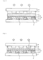
- Figs. 5 and 6 show examples of conventional organic EL displays.
- TFTs 7 and under electrodes 22 are formed on a supporting substrate 1.
- Insulative members 8, organic luminescent mediums 21, upper electrodes 23, a passivation layer 3, a flattening layer 9 and color conversion layers 5 are sequentially formed thereon.
- a transparent substrate 6 is arranged on the uppermost surface.
- An under electrode 22, organic luminescent medium 21 and upper electrode 23 constitute an organic EL element 2.
- the passivation layer 3 performs the function of sealing, and prevents undesired materials generated from and impurities contained in the color conversion layers 5 from penetrating and transmitting into the organic EL elements 2.
- TFTs 7 and under electrodes 22 are formed on a supporting substrate 1.
- Insulative members 8, organic luminescent mediums 21, upper electrodes 23, a passivation layer 4, a flattening layer 9 and color conversion layers 5 are sequentially formed thereon.
- a transparent substrate 6 is arranged on the uppermost surface.
- organic EL displays are of so-called top emission type on the basis of the supporting substrate of organic EL element.
- the color conversion layers 5 adjust/convert light emitted from the organic EL elements 2 and desired light is taken out through the transparent substrate 6. Arrows in the figures show the direction of taking out light.
- organic EL displays are required to improve their durability. That is, in the organic EL display shown in Fig. 5, the conditions under which the passivation layer 3 is formed on the organic EL elements 2 cannot be severe, since the organic luminescent mediums 21 constituting the organic EL elements 2 are organic materials liable to be damaged. Further volatile components may be generated from the organic luminescent mediums 2 when forming the passivation layer 3. As a result, there is the following possibility; A passivation layer 3 is neither densified nor pin-hole less. Volatile components such as monomers and water generated from the color conversion layers 5 transmit through the passivation layer 3. Non-emitting parts such as dark spots then occur in the emitting area of the organic EL elements 2. Consequently an organic EL display with a high durability cannot be obtained.
- the conditions under which the passivation layer 4 is formed on the color conversion layers 5 cannot be severe, since the color conversion layers 5 contain organic materials liable to be damaged. Further volatile components may be generated from the color conversion layers 5 when forming the passivation layer 4. As a result, there is the following possibility; A passivation layer 4 is neither densified nor pin-hole less. Volatile components such as monomers and water generated from the color conversion layers 5 transmit through the passivation layer 4. Non-emitting parts such as dark spots then occur in the emitting area of the organic EL elements 2. Consequently an organic EL display with a high durability cannot be obtained.
- the present invention is made to solve the above problems and an object thereof is to provide an organic EL display excellent in duability with less occurrence of non-emitted parts such as dark spots and a production method thereof.
- Another layer can be provided in the constituent members so far as advantageous effects of the present invention can be obtained.
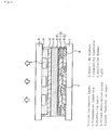
- Fig. 1 is a schematic view showing an organic EL display that is an embodiment according to the present invention.
- TFTs 7 and under electrodes 22 are formed on a supporting substrate 1.
- Insulative members 8, organic luminescent mediums 21, upper electrodes 23, a first passivation layer 3, a second passivation layer 4, a flattening layer 9 and color conversion layers 5 are sequentially formed thereon.
- a transparent substrate 6 is arranged on the uppermost surface.
- An under electrode 22, an organic luminescent medium 21 and an upper electrode 23 constitute an organic EL element 2. Arrows show the direction of taking our light. This device is of top emission type where light is taken out from the side opposite to the supporting substrate 1.
- the organic luminescent mediums 21 therebetween Upon applying voltage across the under and upper electrodes 22 and 23, the organic luminescent mediums 21 therebetween emit light. The light passes through the first and second passivation layers 3 and 4 to the color conversion layers 5. The color conversion layers 5 adjust/convert the color of light emitted by the organic EL elements 2 to emit red, green or blue light as needed. The light of three colors is taken out through the transparent substrate 6.
- the passivation layers 3 and 4 may be the same as or different from each other.
- the materials and thicknesses of passivation layers will be described later.
- the organic EL elements 2 and insulative members 8 are formed on the supporting substrate 1 by a known method and sealed with the first passivation layer 3 to obtain an organic EL element substrate (first substrate)
- the color conversion layers 5 are formed on the transparent substrate 6 by a known method and flattened with the flattening layer 9. The resultant substrate is then sealed with the second passivation layer 4 to obtain a color conversion substrate (second substrate).
- the organic EL element substrate is adhered to the color conversion substrate such that the first passivation layer 3 faces the second passivation layer 4, thereby forming the organic EL display of the embodiment.
- Both the substrates can be adhered with an adhesive and the like.
- the elution of organic components and generation of gas and the like can be suppressed in the production line, since the organic EL element substrate and color conversion substrate are sealed with the passivation layers, respectively. Further the moisture control can be easily performed, since care may not be taken to the absorption of water to the substrates. In addition, these substrates can be easily handled similarly to a glass substrate. They can be washed after they have been produced.
- the process of the embodiment can facilitate the handling at the time of production and enhance the manufacturing efficiency compared with, for example, a process where each layer is laminated on a substrate.
- an intermediate layer such as an adhesive layer or stress relaxation layer may be provided between the first and second passivation layers 3 and 4.
- a proper intermediate layer can not only relax a (mechanical or thermal) stress difference between the organic EL element and color conversion substrates but also prevent the braking of the first and second passivation layers 3 and 4 caused by their contact.
- the material of intermediate layer is not limited but the intermediate layer is preferably made of an inert fluid.
- the inert fluid is a fluid that does not oxidizes a cathode of the organic EL elements 2 and neither penetrates into nor is dissolved in organic materials of the organic EL elements 2.
- Illustrative examples thereof are inert gases such as nitrogen, argon and helium, and inert liquids such as fluoro-hydrocarbons and silicon oils. Among these, fluoro-hydrocarbons are preferred.
- a stress relaxation layer is preferably made of a highly-elastic material with transparency, small Yong's modulus and high tension rate.
- Various gels and rubbers such as silicone rubbers are exemplified.
- Such a material preferably has a Yong's modulus of 0.1 to 10 MPa to relax stress. It preferably has a transmittance of 50% or more in the case where light is taken out through the stress relaxation layer.
- the thickness of the stress relaxation layer is not limited so far as the layer can sufficiently absorb stress and impact. However the layer preferably have a substantially uniform and thin thickness to make an organic EL display thin, for example 0.001 ⁇ m to 200 ⁇ m, more preferably 0.01 ⁇ m to 10 ⁇ m.
- the layer has a thickness thinner than 0.001 ⁇ m, it may not sufficiently absorb stress and impact. If the layer has thickness thicker than 200 ⁇ m, the display properties of an organic EL display may be remarkably degraded, for example, color mixture may reduce its color reproducibility and increase the viewing angle dependency.
- the layer can be formed by application (spin coater, roll coater) and so on.
- the stress relaxation layer may be constructed of spacers distributed and filler filling space between spacers.
- Materials of the spacers include silica spacers, plastic spacers and glass. Fillers include liquid silicone
- the spacers can be formed with a spacer distributing device used in apparatuses for manufacturing liquid crystal displays.
- separating walls and a drying agent may be provided as an intermediate layer.
- An organic film such as carbon nitride may be provided as an intermediate layer for relaxing stress.
- Three or more passivation layers may be arranged.
- the present invention can be suitably applied to devices with no TFTs although the device with TFTs has been described above as the embodiment.
- the supporting substrate in the organic EL display is a member for supporting the organic EL element and the like. Therefore the substrate is preferably excellent in mechanical strength and dimension stability.
- Materials for such a substrate include glass plates, metal plates, ceramic plates and plastic plates such as polycarbonate resins, acrylic resins, vinyl chloride resins, polyethylene terephthalate resins, polyimide resins, polyester resins, epoxy resins, phenol resins, silicon resins, fluorine-containing resins and polyethersulfone resins.
- polycarbonate resins acrylic resins, vinyl chloride resins, polyethylene terephthalate resins, polyimide resins, polyester resins, epoxy resins, phenol resins, silicon resins, fluorine-containing resins and polyethersulfone resins.
- the supporting substrate 1 made of these materials is preferably subjected to a moisture proof treatment or hydrophobic treatment by forming an inorganic film or applying a fluorine-containing resin.
- the supporting substrate preferably has a small water content and gas permeability coefficient.
- preferred water content and gas permeability coefficient are 0.0001% by weight or less and 1 ⁇ 10 -13 cc ⁇ cm/cm 2 ⁇ sec.cmHg or less, respectively.
- the supporting substrate is not necessarily transparent.
- the organic EL element is constructed of the organic luminescent medium, the upper electrode and the under electrode which hold the medium therebetween.
- Each constituent element of the organic EL element i.e. organic luminescent medium (1), upper electrode (2) and under electrode (3) will be sequentially described below.
- the organic luminescent medium can be defined as a medium containing an organic luminescent layer wherein electrons and holes are recombined with each other, thereby allowing EL emission.
- This organic luminescent medium can be made, for example, by laminating the following layers (a) to (g) on an anode:
- the structure (d) is preferably used since it can give a higher luminescent brightness and is also superior in durability.
- the upper electrode is arranged over entire the surface of display area.
- the upper electrode corresponds to an anode or a cathode layer dependently on the structure of the organic EL element.
- the upper electrode corresponds to an anode layer
- a material having a work function of less than 4.0 eV in order to make electron-injection easy.
- materials for the upper electrode include only one or combinations of two or more selected from indium tin oxide (ITO), indium zinc oxide (IZO), copper indium (CuIn), tin oxide (SnO 2 ), zinc oxide (ZnO), antimony oxide (Sb 2 O 3 , Sb 2 O 4 , Sb 2 O 5 ), aluminum oxide (Al 2 O 3 ) and so on.
- a constituent material of the upper electrode can be selected from the group consisting of light transmitting metal films, nondegenerate semiconductors, organic conductors, semiconductive carbon compounds and so on.
- Preferred organic conductors include conductive conjugated polymers, oxidizer-added polymers, reducer-added polymers, oxidizer-added low molecules or reducer-added low molecules.
- Examples of oxidizers added to an organic conductor include Lewis acids such as iron chloride, antimony chloride and aluminum chloride. Further Examples of reducers added to an organic conductor include alkali metals, alkali-earth metals, rare-earth metals, alkali compounds, alkali-earth compounds or rare-earth compounds. Examples of conductive conjugated polymers include polyanilines and derivatives thereof, polytiophens and derivatives thereof and Lewis-acid-added amine compounds.
- nondegenerate semiconductors include oxides, nitrides or chalcogenide compounds.
- Preferred examples of carbon compounds include amorphous C, graphite or diamond like C.
- inorganic semiconductors examples include ZnS, ZnSe, ZnSSe, MgS, MgSSe, CdS, CdSe, CdTe or CdSSe.
- the thickness of the upper electrode is decided preferably its sheet resistance or the like.
- the thickness of the upper electrode is preferably in the range of 50nm to 5000nm, more preferably 100nm or more. Such a thickness allows a uniform thickness distribution and light transmission of 60% or more of EL emission as well as a sheet resistance of the upper electrode of 15 ⁇ / ⁇ or less, more preferably 10 ⁇ / ⁇ or less.
- the under electrode is individually separatively arranged per pixel in a plane pattern.
- the under electrode corresponds to an anode or cathode layer dependently on the structure of the organic EL display.
- a material having a smaller work function for example, a metal, an alloy, an electrically conductive compound, a mixture thereof or a material containing at least one of them having a work function of less than 4.0 eV.
- the materials for example, it is preferred to use one or a combination of two or more selected from sodium, sodium-potassium alloys, cesium, magnesium, lithium, magnesium-silver alloys, aluminum, aluminum oxide, aluminum-lithium alloys, indium, rare earth metals, mixtures of these metals and organic luminescence medium materials, mixtures of these metals and electron injecting layer materials, and so on.
- materials of the under electrode it is not necessary for materials of the under electrode to have transparency since luminescence is got from the upper electrode side. It is preferably made rather from light-absorbing conductive materials. This structure enhances the display contrast of organic EL display.
- preferable light-absorbing conductive materials include semiconductive carbonate materials, colored organic compounds, combinations of the above reducers and oxidizers, and colored conductive oxide (transition metal oxides such as VOx, MoOx, WOx and etc.).
- the thickness of the under electrode is not particularly limited as well as the upper electrode. However, it is preferably in the range of, for example, 10nm to 1000nm, more preferably 10nm to 200nm.
- the insulative member (electric insulator) in the organic EL display of the embodiments is formed near or around the organic EL element.
- the insulative member is used for high resolution of a whole organic EL display, and for prevention of short circuits between the under and upper electrodes.
- the insulative member is also used for protection of the TFTs and as a base for coating of the under electrode of the organic EL element flatly.
- the insulative member may be called, a partition, a spacer, a flattening film or the like if necessary.
- the invention embraces all of them.
- the insulative members are provided to bury gaps between the under electrodes formed separately disposed per pixel. That is, the insulative members are disposed along boundaries between pixels.
- Examples of materials for the insulative member usually include acrylic resins, polycarbonate resins, polyimide resins, fluorinated polyimide resins, benzoguanamine resins, melamine resins, cyclic polyolefins, Novolak resins, polyvinyl cinnamates, cyclic rubbers, polyvinyl chloride resins, polystyrenes, phenol resins, alkyd resins, epoxy resins, polyurethane resins, polyester resins, maleic acid resins, and polyamide resins.
- the insulative member is made of an inorganic oxide
- preferred inorganic oxides include silicon oxide (SiO 2 or SiO x ), aluminum oxide (Al 2 O 3 or AlO x ), titanium oxide (TiO 3 or TiO x ), yttrium oxide (Y 2 O 3 or YO x ), germanium oxide (GeO 2 or GeO x ), zinc oxide (ZnO), magnesium oxide (MgO), calcium oxide (CaO), boric acid (B 2 O 3 ), strontium oxide (SrO), barium oxide (BaO), lead oxide (PbO), zirconia (ZrO 2 ), sodium oxide (Na 2 O) lithium oxide (Li 2 O), potassium oxide (K 2 O).
- the value x in the above inorganic compounds is in the range of 1 ⁇ x ⁇ 3.
- acrylic resins In the case that heat-resistance is required for the member, it is preferred to use acrylic resins, polyimide resins, fluorinated polyimides, cyclic olefins, epoxy resins, or inorganic oxides.
- These insulative members when being organic, can be worked into a desired pattern by introducing a photosensitive group thereto and using a photolithography method, or can be formed into a desired pattern by printing.
- the thickness of the insulative member depends on the resolution of display, or unevenness of other members combined with the organic EL element, and is preferably 10 nm to 1 mm. This is because such a structure makes it possible to make the unevenness of the TFTs and the like sufficiently flat.
- the thickness of the insulative member is more preferably 100 nm to 100 ⁇ m, and still more preferably 100 nm to 10 ⁇ m.
- Examples of materials for the passivation layer include transparent resins, sealing liquids and transparent inorganic materials.
- the constituent material of the first passivation layer may be the same as or different from that of the second passivation layer.
- Each passivation layer may be of monolayer or multi-layer structure.
- transparent resins which can be used as a constituent material for the passivation layer include polyphenyl methacrylate, polyethylene terephthalate, poly-o-chlorostyrene, poly-o-naphthyl methacrylate, polyvinyl naphthalene, polyvinyl carbazole and polyester containing fluorene skeleton.
- a transparent resin As a material for the passivation layer, it is preferably to comprise ultravioiet-ray curing resins, visible light curing resins, thermosetting resins or adhesives using them.
- ultravioiet-ray curing resins include commercially available products such as Luxtrak LCR0278, 0242D (both of which are made by Toagosei Co., Ltd.), TB3102 (epoxy type, made by Three Bond Co., Ltd.)and Venefix VL (acrylic type, made by Adel Co., Ltd.).
- transparent inorganic materials which can be used as a material constituting the passivation layer include SiO 2 , SiO x , SiO x N y , Si 3 N 4 , Al 2 O 3 , AlO x N y , TiO 2 , TiO x , SiAlO x N y , TiAlO x , TiAlO x N y , SiTiO x and SiTiO x N y wherein x is preferably 0.1 to 4 and y is preferably 0.1 to 3.
- the materials also include a sodium-lime grass; grasses containing barium and strontium; lead grass; aluminosilicate grass; borosilicate glass; bariumborosilicate glass, pyrex grass; vycor grass; grasses containing at least a silicon oxide, boron oxide and aluminum oxide; grasses containing at least a silicon oxide, boron oxide, aluminum oxide and alkaline metal oxide; grasses containing at least a silicon oxide, boron oxide, aluminum oxide and alkaline earth metal oxide; and grasses containing at least a silicon oxide, boron oxide, aluminum oxide and rare earth metal oxide.
- elements with a small atomic diameter form network around elements with a large atomic diameter.
- a more densified passivation layer can be preferably formed.
- a passivation layer may be preferably formed by repeatedly laminating these transparent inorganic materials and transparent resins. Even if a pin hole is formed in a film of a transparent inorganic material, a transparent resin can fill the pin hole and flatten the film, thereby preventing the generation of a pin hole.
- a passivation layer may be preferably formed by repeatedly laminating these transparent inorganic materials and carbon nitride.
- Carbon nitride can absorb stress of a transparent inorganic material, thereby enhancing thermal shock resistance and preventing cracks and so on.
- the film is preferably formed at a low temperature (100°C or lower) and a slow film-forming speed in order that the organic EL element is not deteriorated.
- methods such as sputtering, counter target sputtering, vapor deposition or CVD are preferred.
- These transparent inorganic materials are preferably amorphous since the amorphous films have a high effect of shielding moisture, oxygen, low molecular monomers and so on and suppress the deterioration of the organic EL element.
- Examples of a sealing liquid constituting the passivation layer include fluorinated hydrocarbons and fluorinated olefin oligomers.
- An aromatic ring containing compound, a fluorine skeleton containing compound, a bromine containing compound, or a sulfur containing compound, and compounds having a high refractive index for example, metalic compounds such as alkoxytitanium (dimethoxytitanium, diethoxytitanium) and alkoxytitaniums may be added to adjust a refractive index.
- the thickness of a passivation layer is not limited but the following relation is preferably satisfied. 0.001 ⁇ m ⁇ T1+T2 ⁇ 200 ⁇ m wherein T1 is the thickness of a first passivation layer and T2 is the thickness of a second passivation layer. If (T1+T2) is 0.001 ⁇ m or less, a passivation layer may almost be mono-atomic layer and have an island-like structure without densification. As a result, the passivation layer may lose a passivating effect, i.e., blocking volatile components from organic luminescent mediums and color conversion layers. If (T1+T2) is 200 ⁇ m or more, there is the following disadvantageous possibility.
- a first passivation layer closely contacts organic EL elements and a second passivation layer closely contacts color conversion layers.
- a flattening layer which flattens color conversion layers formed on a transparent substrate, may be made of transparent materials.
- the same materials as those used in a passivation layer may be preferably used as a material of a flattening layer.
- the thickness of a flattening layer is not limited but preferably thinner to make an organic EL display thin.
- the thickness of both a flattening layer and color conversion layers is preferably 1 ⁇ m to 10 ⁇ m.
- the color conversion layer adjusting and/or converting a luminescent color of organic EL element contains the following three cases: (i) color filter, (ii) fluorescent medium and (iii) combination of a color filter and a fluorescent medium.
- the color conversion layer preferably contains a fluorescent medium.
- the fluorescent medium enables the emission of color light other than inherent organic EL light and the strengthening of weak color light. Thus power consumption of an organic EL display can be reduced.
- the combination of a color filter and a fluorescent medium (iii) is very preferably because of improving the brightness despite low-power, the color purity of display, and the balance of display colors at the time of emitting each of three primary colors.
- a blue pixel has only a blue color filter
- a green pixel has a fluorescent medium converting blue light to green light and a green color filter
- a red pixel has a fluorescent medium converting blue light to red light and a red color filter.
- the surface may be decorated with, for example, organic materials and metal oxides such as silica to prevent the removal of S, Se and the like by a reactive component of a binder resin.
- organic materials and metal oxides such as silica
- the surface of CdSe fine particles may be coated with a shell of a semiconductive material with a higher band gap energy such as ZnS. This facilitates the entrapment of electrons generated in central fine particles.
- the above fluorescent dyes may be used alone or in combination of two or more.
- the same binder resins for the color filter can be used here.
- the same forming methods for the color filter can be used for the fluorescent medium.
- the thickness of the fluorescent medium is not particularly limited.
- the thickness is preferably 10nm to 1,000 ⁇ m, more preferably 0.1 ⁇ m to 500 ⁇ m, and still more preferably 5 ⁇ m to 100 ⁇ m.
- the transparent substrate covers at least the emitting area of the organic EL display.
- the same materials for the supporting substrate can be used.
- a glass plate or a ceramic substrate having a high effect of shielding moisture or oxygen can be used.
- the form of the transparent substrate is not particularly limited, but preferably, for example, a plate or a cap.
- the thickness thereof is preferably in the range of 0.01 to 5mm.
- the transparent substrate is fitted into a groove or the like made in a part of the supporting substrate under pressure and then fixed thereto, or that it is fixed to a part of the supporting substrate with a photo-curing adhesive agent or the like.
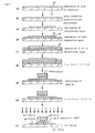
- Figs. 2 (a) to (i) are views showing the steps of forming a polysilicon TFT.
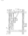
- Fig. 3 is a circuit diagram showing the connection structure of electric switch with the polysilicon TFT.
- Fig. 4 is a plane view showing the connection structure of electric switch with the polysilicon TFT.
- ⁇ -Si layer 40 was laminated on a glass substrate 2 of 112mm x 143mm x 1.1mm (OA2 glass, Nippon Electric Glass Co., Ltd.) by low pressure chemical vapor deposition (LPCVD) and the like (Fig. 2 (a)).
- LPCVD low pressure chemical vapor deposition
- the ⁇ -Si layer 40 was irradiated with an excimer laser such as a KrF (248nm) laser to be subjected to annealing crystallization, thereby converting ⁇ -Si to polysilicon (Fig. 2 (b)).
- This polysilicon was patterned into an island form by photolithography (Fig. 2 (c)).
- An insulative gate material 42 was laminated on the island-like polysilicon 41 and the surface of the substrate 2 by chemical vapor deposition (CVD) and the like to form a gate oxide insulative layer 42 (Fig. 2 (d)).
- a gate electrode 43 was then formed as a film by depositing or sputtering (Fig. 2 (e)), and patterned with anodization (Figs. 2 (f) to (h)). Further doping regions were formed by ion doping (ion implantation), thereby forming active layers as a source 45 and a drain 47 to obtain a polysilicon TFT (Fig. 2 (i)).
- the gate electrode 43 (and a scanning electrode 50 and a bottom electrode of a capacitor 57 shown in Fig. 4) was Al, while the source 45 and drain 47 of TFT were of n+ type.
- a 500nm-thick inter-insulator (SiO 2 ) was formed on the active layers by CRCVD. Thereafter signal electrode lines 51, common electrode lines 52 and top electrodes 57 (Al) of capacitors were formed.
- the source electrodes of second transistors (Tr2) 56 were connected to the common electrodes.
- the drains of first transistors (Tr1) 55 were connected to the signal electrodes. Refer to Figs. 3 and 4.
- Each TFT was connected to each electrode by properly opening the inter-insulator SiO 2 by wet etching with hydrofluoric acid.
- Cr and ITO films were sequentially deposited by sputtering in thicknesses of 2000 ⁇ and 1300 ⁇ , respectively.
- a positive resist (HPR204, FUJIFILM Arch Co., Ltd.) was applied on the substrate by spin coating.
- the resultant substrate was exposed to ultraviolet rays with a photo mask of 90 ⁇ m x 320 ⁇ m for a dot pattern, subjected to development with a developing solution of TMAH (tetramethy ammonium hydroxide) and baked at 130°C to obtain a resist pattern.
- TMAH tetramethy ammonium hydroxide
- ITO in the exposed parts was etched by an ITO etchant of 47% hydrobromic acid and then Cr was etched by cerium nitrate ammonium/perchloric acid aqueous solution (HCE: NAGASE & Co., Ltd.).
- the resist was processed by a stripping solution mainly containing ethanolamine (N303: NAGASE & Co., Ltd.) to produce a Cr/ITO pattern (under electrode: anode).
- Tr2 56 was connected to the under electrode 10 via an opening 59 (Fig. 4).
- a negative resist V259BK: Nippon Steel Chemical Co., Ltd.
- TMAH tetramethyl ammonium hydroxide
- the substrate with the inter-insulative film thus obtained was subjected to ultrasonic cleaning with purified water and isopropyl alcohol, dried with air blow and thereafter cleaned with ultraviolet rays.
- the TFT substrate was moved into an organic deposition device (ULVAC Co., Ltd.) and fixed in a substrate holder.
- Heating boards made of molybdenum were filled in advance 4,4',4"-tris[N-(3-methylphenyl)-[N-phenylamino]triphenylamine(MTDATA) and 4,4'-bis[N-(1-naphtyl)-N-phenylamino]biphenyl(NPD) as a hole injecting material, 4,4'-bis(2,2'-diphenylvinyl)biphenyl(DPVBi) as a host of luminescent material, 1,4-bis[4-(N,N'-diphenylaminostyrylbenzene)](DPAVB) as a dopant, tris(8-quinolinol)aluminum (Alq) and lithium as electron injecting material and cathode, respectively.
- MTDATA was deposited in a thickness of 60nm at a deposition speed of 0.1 to 0.3 nm/second
- NPD was deposited in a thickness of 20nm at a deposition speed of 0.1 to 0.3 nm/second, as a hole injecting layer
- DPVBi and DPAVB were co-deposited in a thickness of 50nm at a deposition speed of 0.1 to 0.3 nm/second and 0.03 to 0.05 nm/second, respectively as an emitting layer
- Alq was deposited in a thickness of 20nm at 0.1 to 0.3 nm/second as an electron injecting layer
- Alq and Li were co-deposited in a thickness of 20nm at 0.1 to 0.3 nm/second and 0.005 nm/second, respectively as a cathode.
- An IZO film was formed at a depositing rate of 0.1 to 0.3 nm/second in a thickness of 200nm as a taking out electrode of under electrode to obtain an organic EL element.
- An organic EL element substrate was thus obtained.
- a black matrix (BM) material V259BK (Nippon Steal Chemical Co., Ltd.) was spin-coated on a supporting substrate (a transparent substrate) of 102mm by 133mm by 1.1mm (OA2 glass, Nippon Electric glass Co., Ltd.). Thereafter, it was exposed to ultraviolet rays with a photo mask for making a lattice pattern, developed with a developing solution of 2% aqueous solution of sodium carbonate and baked at 200°C to obtain a black matrix pattern (film thickness of 1.5 ⁇ m).
- the resultant substrate was exposed to ultraviolet rays with a photo mask for forming the pattern of 320 rectangle stripes (90 ⁇ m line, 240 ⁇ m gap) in alignment with the position of the black matrix, developed with a 2% aqueous solution of sodium carbonate and baked at 200°C to form the pattern of a blue filter (film thickness of 1.5 ⁇ m).
- a green filter material containing azo based pigment and phthalocyanine bromide type one V259G (Nippon Steal Chemical Co., Ltd.), was spin-coated.
- the resultant substrate was exposed to ultraviolet rays with a photo mask for forming the pattern of 320 rectangle stripes (90 ⁇ m line 240 ⁇ m gap) in alignment with the position of the black matrix, developed with a 2% aqueous solution of sodium carbonate and baked at 200°C to form the pattern of a green filter (film thickness of 1.5 ⁇ m) adjacent the blue filter.
- a red filter material containing an azo based pigment and diketopyrrolopyarte type one V259R (manufactured by Nippon Steal Chemical Co., Ltd.) was spin-coated.
- the resultant substrate was exposed to ultraviolet rays with a photo mask for forming the pattern of 320 rectangle stripes (90 ⁇ m line, 240 ⁇ m gap) in alignment with the position of the black matrix, developed with a 2% aqueous solution of sodium carbonate and baked at 200°C to form the pattern of a red filter (film thickness of 1.5 ⁇ m) between the blue filter and green filter.
- This ink was spin-coated on the above substrate.
- the resultant substrate was exposed to ultraviolet rays above the green filter, developed with a 2% aqueous solution of sodium carbonate and baked at 200°C to form the pattern of a green converting film (film thickness 10 ⁇ m) above the green filter.
- This ink was spin-coated on the above substrate.
- the resultant substrate was exposed to ultraviolet rays above the red filter, developed with a 2% aqueous solution of sodium carbonate and baked at 180°C to form the pattern of a red converting film (film thickness 10 ⁇ m) above the red filter.
- an acrylic acid based thermosetting resin (V259PH, Nippon Steel Chemical Co., Ltd.) was spin-coated on the above substrate as a flattening film and baked at 180°C to form a 12 ⁇ m-thick flattening film.
- the organic EL element substrate and the color conversion substrate produced above were placed in a dry box through which dried nitrogen flowed.
- a cationic photosetting type adhesive (3102: Three Bond Co., Ltd.) was applied around the display part (emission part) of the organic EL element substrate by using a dispenser.
- An active organic EL display ( Figure 1) was produced as described above. Upon applying a voltage of DC 7 V between the under electrode (ITO/Cr) and upper electrode (IZO) of the display (under electrode: (+), upper electrode: (-)), light was emitted the intersections of electrodes, pixels.
- An organic EL display ( Figure 5) was produced under the same conditions as those of Example 1 except that a passivation layer was not formed on the color conversion substrate. The reliability of organic EL display was evaluated in the same way as in Example 1.
- An organic EL display ( Figure 6) was produced under the same conditions as those of Example 1 except that a passivation layer was not formed on the organic EL element substrate. The reliability of organic EL display was evaluated in the same way as in Example 1.
- the present invention can provide an organic EL display excellent in duability with less occurrence of non-emitted parts such as dark spots and a production method thereof.
Abstract
An organic electroluminescent display including: a
supporting substrate; an organic electroluminescent
element; a first passivation layer; a second passivation
layer; a color conversion layer for adjusting and/or
converting the color of a light emitted from the organic
electroluminescent element; and a transparent substrate
formed in sequence. Since the display has two passivation
layers, a pinhole pass can be effectively blocked, thereby
enhancing the sealing properties. Consequently a non-emission
region such as a dark spot is hardly formed, and
therefore the display can have excellent durability.
Description
The present invention relates to an organic EL
(electroluminescent) display and its production, the
display suitably employed in displays for personal and
industrial uses, specifically cell-phone, PDA, car-navigation,
monitor, television and the like.
An organic EL display is constructed from organic EL
elements with an organic luminescent medium held between
opposite electrodes. If a voltage is applied across the
electrodes, electrons injected from one electrode recombine
with holes from another electrode in an organic emitting
layer of the organic luminescent medium. The organic
luminescent molecules in the organic emitting layer change
to the exited state by the recombination energy and then
return to the ground state. At this time energy is
discharged. The organic EL element emits light by taking
out this energy as light.
An organic EL display constructed from organic EL
elements of such luminescent principle is completely solid
and characterized by excellent visibility, light weight,
thin thickness, and low driving voltage of several volts.
Thus organic EL displays are expected to be used as color
displays and have been eagerly researched at present.
Figs. 5 and 6 show examples of conventional organic
EL displays.
In the organic EL display shown in Fig. 5 (for
example, US-B-6268695 and JP-A-2000-223264), TFTs 7 and
under electrodes 22 are formed on a supporting substrate 1.
Insulative members 8, organic luminescent mediums 21, upper
electrodes 23, a passivation layer 3, a flattening layer 9
and color conversion layers 5 are sequentially formed
thereon. A transparent substrate 6 is arranged on the
uppermost surface. An under electrode 22, organic
luminescent medium 21 and upper electrode 23 constitute an
organic EL element 2. The passivation layer 3 performs the
function of sealing, and prevents undesired materials
generated from and impurities contained in the color
conversion layers 5 from penetrating and transmitting into
the organic EL elements 2.
In the organic EL display shown in Fig. 6 (for
example, JP-A-H10-12383, JP-A-H8-279394 and JP-A-H11-260562),
TFTs 7 and under electrodes 22 are formed on a
supporting substrate 1. Insulative members 8, organic
luminescent mediums 21, upper electrodes 23, a passivation
layer 4, a flattening layer 9 and color conversion layers 5
are sequentially formed thereon. A transparent substrate 6
is arranged on the uppermost surface.
These organic EL displays are of so-called top
emission type on the basis of the supporting substrate of
organic EL element. The color conversion layers 5
adjust/convert light emitted from the organic EL elements 2
and desired light is taken out through the transparent
substrate 6. Arrows in the figures show the direction of
taking out light.
These organic EL displays are required to improve
their durability. That is, in the organic EL display shown
in Fig. 5, the conditions under which the passivation layer
3 is formed on the organic EL elements 2 cannot be severe,
since the organic luminescent mediums 21 constituting the
organic EL elements 2 are organic materials liable to be
damaged. Further volatile components may be generated from
the organic luminescent mediums 2 when forming the
passivation layer 3. As a result, there is the following
possibility; A passivation layer 3 is neither densified nor
pin-hole less. Volatile components such as monomers and
water generated from the color conversion layers 5 transmit
through the passivation layer 3. Non-emitting parts such
as dark spots then occur in the emitting area of the
organic EL elements 2. Consequently an organic EL display
with a high durability cannot be obtained.
In the organic EL display shown in Fig. 6, the
conditions under which the passivation layer 4 is formed on
the color conversion layers 5 cannot be severe, since the
color conversion layers 5 contain organic materials liable
to be damaged. Further volatile components may be
generated from the color conversion layers 5 when forming
the passivation layer 4. As a result, there is the
following possibility; A passivation layer 4 is neither
densified nor pin-hole less. Volatile components such as
monomers and water generated from the color conversion
layers 5 transmit through the passivation layer 4. Non-emitting
parts such as dark spots then occur in the
emitting area of the organic EL elements 2. Consequently
an organic EL display with a high durability cannot be
obtained.
The present invention is made to solve the above
problems and an object thereof is to provide an organic EL
display excellent in duability with less occurrence of non-emitted
parts such as dark spots and a production method
thereof.
According to the present invention, there are
provided the following organic EL display and its
production method.
wherein the following formula is satisfied,
wherein the intermediate layer comprises an inert fluid.
Another layer can be provided in the constituent
members so far as advantageous effects of the present
invention can be obtained.
An organic EL display of the present invention will
be described with reference to drawings.
Fig. 1 is a schematic view showing an organic EL
display that is an embodiment according to the present
invention.
In the organic EL display shown in this figure, TFTs
7 and under electrodes 22 are formed on a supporting
substrate 1. Insulative members 8, organic luminescent
mediums 21, upper electrodes 23, a first passivation layer
3, a second passivation layer 4, a flattening layer 9 and
color conversion layers 5 are sequentially formed thereon.
A transparent substrate 6 is arranged on the uppermost
surface. An under electrode 22, an organic luminescent
medium 21 and an upper electrode 23 constitute an organic
EL element 2. Arrows show the direction of taking our
light. This device is of top emission type where light is
taken out from the side opposite to the supporting
substrate 1.
Upon applying voltage across the under and upper
electrodes 22 and 23, the organic luminescent mediums 21
therebetween emit light. The light passes through the
first and second passivation layers 3 and 4 to the color
conversion layers 5. The color conversion layers 5
adjust/convert the color of light emitted by the organic EL
elements 2 to emit red, green or blue light as needed. The
light of three colors is taken out through the transparent
substrate 6.
In this device, two layers of the first and second
passivation layers 3 and 4 are provided as a passivation
layer. Thus even if a pin hole occurs in one passivation
layer, another passivation layer can effectively obstruct
the path of the pin hole. Consequently non-emitting parts
are hardly generated in the device with an enhanced sealing
property. As a result there can be provided an organic EL
display with a synergistically high durability.
The passivation layers 3 and 4 may be the same as or
different from each other. The materials and thicknesses
of passivation layers will be described later.
Next a process for producing the organic EL display
is described below.
Firstly the organic EL elements 2 and insulative
members 8 are formed on the supporting substrate 1 by a
known method and sealed with the first passivation layer 3
to obtain an organic EL element substrate (first substrate)
The color conversion layers 5 are formed on the
transparent substrate 6 by a known method and flattened
with the flattening layer 9. The resultant substrate is
then sealed with the second passivation layer 4 to obtain a
color conversion substrate (second substrate).
Next the organic EL element substrate is adhered to
the color conversion substrate such that the first
passivation layer 3 faces the second passivation layer 4,
thereby forming the organic EL display of the embodiment.
Both the substrates can be adhered with an adhesive and the
like.
In the process, the elution of organic components and
generation of gas and the like can be suppressed in the
production line, since the organic EL element substrate and
color conversion substrate are sealed with the passivation
layers, respectively. Further the moisture control can be
easily performed, since care may not be taken to the
absorption of water to the substrates. In addition, these
substrates can be easily handled similarly to a glass
substrate. They can be washed after they have been
produced.
Thus the process of the embodiment can facilitate the
handling at the time of production and enhance the
manufacturing efficiency compared with, for example, a
process where each layer is laminated on a substrate.
The present invention is not limited to the
embodiment and various modifications may be made. For
example, an intermediate layer such as an adhesive layer or
stress relaxation layer may be provided between the first
and second passivation layers 3 and 4. A proper
intermediate layer can not only relax a (mechanical or
thermal) stress difference between the organic EL element
and color conversion substrates but also prevent the
braking of the first and second passivation layers 3 and 4
caused by their contact. The material of intermediate
layer is not limited but the intermediate layer is
preferably made of an inert fluid. The inert fluid is a
fluid that does not oxidizes a cathode of the organic EL
elements 2 and neither penetrates into nor is dissolved in
organic materials of the organic EL elements 2.
Illustrative examples thereof are inert gases such as
nitrogen, argon and helium, and inert liquids such as
fluoro-hydrocarbons and silicon oils. Among these, fluoro-hydrocarbons
are preferred.
A stress relaxation layer is preferably made of a
highly-elastic material with transparency, small Yong's
modulus and high tension rate. Various gels and rubbers
such as silicone rubbers are exemplified. Such a material
preferably has a Yong's modulus of 0.1 to 10 MPa to relax
stress. It preferably has a transmittance of 50% or more
in the case where light is taken out through the stress
relaxation layer. The thickness of the stress relaxation
layer is not limited so far as the layer can sufficiently
absorb stress and impact. However the layer preferably have
a substantially uniform and thin thickness to make an
organic EL display thin, for example 0.001µm to 200µm, more
preferably 0.01µm to 10µm. If the layer has a thickness
thinner than 0.001µm, it may not sufficiently absorb stress
and impact. If the layer has thickness thicker than 200µm,
the display properties of an organic EL display may be
remarkably degraded, for example, color mixture may reduce
its color reproducibility and increase the viewing angle
dependency. The layer can be formed by application (spin
coater, roll coater) and so on.
The stress relaxation layer may be constructed of
spacers distributed and filler filling space between
spacers. Materials of the spacers include silica spacers,
plastic spacers and glass. Fillers include liquid silicone
The spacers can be formed with a spacer distributing device
used in apparatuses for manufacturing liquid crystal
displays.
Instead of the spacers, separating walls and a drying
agent may be provided as an intermediate layer. An organic
film such as carbon nitride may be provided as an
intermediate layer for relaxing stress.
Three or more passivation layers may be arranged.
The present invention can be suitably applied to
devices with no TFTs although the device with TFTs has been
described above as the embodiment.
Next the constituent members of the organic EL
display in the embodiment will be each described below.
Ordinary members and structures can be applied if not
otherwise specified. Among these, the most suitable one
can be selected in the device of the present invention.
The supporting substrate in the organic EL display is
a member for supporting the organic EL element and the like.
Therefore the substrate is preferably excellent in
mechanical strength and dimension stability.
Materials for such a substrate include glass plates,
metal plates, ceramic plates and plastic plates such as
polycarbonate resins, acrylic resins, vinyl chloride resins,
polyethylene terephthalate resins, polyimide resins,
polyester resins, epoxy resins, phenol resins, silicon
resins, fluorine-containing resins and polyethersulfone
resins.
In order to avoid the invasion of moisture into the
organic EL display, the supporting substrate 1 made of
these materials is preferably subjected to a moisture proof
treatment or hydrophobic treatment by forming an inorganic
film or applying a fluorine-containing resin.
In particular, in order to avoid the invasion of
moisture into the organic luminescent medium, the
supporting substrate preferably has a small water content
and gas permeability coefficient. Specifically, preferred
water content and gas permeability coefficient are 0.0001%
by weight or less and 1 × 10-13 cc·cm/cm2·sec.cmHg or less,
respectively.
In order to take out EL emission from the side
opposite to the supporting substrate, that is, the upper
electrode side in the invention, the supporting substrate
is not necessarily transparent.
Generally the organic EL element is constructed of
the organic luminescent medium, the upper electrode and the
under electrode which hold the medium therebetween. Each
constituent element of the organic EL element, i.e. organic
luminescent medium (1), upper electrode (2) and under
electrode (3) will be sequentially described below.
The organic luminescent medium can be defined as a
medium containing an organic luminescent layer wherein
electrons and holes are recombined with each other, thereby
allowing EL emission. This organic luminescent medium can
be made, for example, by laminating the following layers
(a) to (g) on an anode:
Among these (a) to (g), the structure (d) is
preferably used since it can give a higher luminescent
brightness and is also superior in durability.
In the embodiments, the upper electrode is arranged
over entire the surface of display area.
The upper electrode corresponds to an anode or a
cathode layer dependently on the structure of the organic
EL element. In the case that the upper electrode
corresponds to an anode layer, it is preferred to use a
material having a large work function, for example, 4.0 eV
or more, in order to make hole-injection easy. In the case
that the upper electrode corresponds to a cathode layer, it
is preferred to use a material having a work function of
less than 4.0 eV in order to make electron-injection easy.
In organic EL displays of top emission type, it is
necessary for the upper electrode to have transparency in
order to get light out through the upper electrode.
Accordingly, in the case that the upper electrode 23
corresponds to the anode layer, materials for the upper
electrode include only one or combinations of two or more
selected from indium tin oxide (ITO), indium zinc oxide
(IZO), copper indium (CuIn), tin oxide (SnO2), zinc oxide
(ZnO), antimony oxide (Sb2O3, Sb2O4, Sb2O5), aluminum oxide
(Al2O3) and so on.
In order to decrease the resistance of the upper
electrode without damaging transparency, only one or
combination of two or more selected from metals such as Pt,
Au, Ni, Mo, W, Cr, Ta and Al is preferably added.
A constituent material of the upper electrode can be
selected from the group consisting of light transmitting
metal films, nondegenerate semiconductors, organic
conductors, semiconductive carbon compounds and so on.
Preferred organic conductors include conductive conjugated
polymers, oxidizer-added polymers, reducer-added polymers,
oxidizer-added low molecules or reducer-added low molecules.
Examples of oxidizers added to an organic conductor
include Lewis acids such as iron chloride, antimony
chloride and aluminum chloride. Further Examples of
reducers added to an organic conductor include alkali
metals, alkali-earth metals, rare-earth metals, alkali
compounds, alkali-earth compounds or rare-earth compounds.
Examples of conductive conjugated polymers include
polyanilines and derivatives thereof, polytiophens and
derivatives thereof and Lewis-acid-added amine compounds.
Preferred examples of nondegenerate semiconductors
include oxides, nitrides or chalcogenide compounds.
Preferred examples of carbon compounds include
amorphous C, graphite or diamond like C.
Examples of inorganic semiconductors include ZnS,
ZnSe, ZnSSe, MgS, MgSSe, CdS, CdSe, CdTe or CdSSe.
The thickness of the upper electrode is decided
preferably its sheet resistance or the like. For example,
the thickness of the upper electrode is preferably in the
range of 50nm to 5000nm, more preferably 100nm or more.
Such a thickness allows a uniform thickness distribution
and light transmission of 60% or more of EL emission as
well as a sheet resistance of the upper electrode of 15Ω/□
or less, more preferably 10Ω/□ or less.
In the embodiments, the under electrode is
individually separatively arranged per pixel in a plane
pattern.
The under electrode corresponds to an anode or
cathode layer dependently on the structure of the organic
EL display. In the case that the under electrode
corresponds to a cathode layer, it is preferred to use a
material having a smaller work function, for example, a
metal, an alloy, an electrically conductive compound, a
mixture thereof or a material containing at least one of
them having a work function of less than 4.0 eV.
As such materials, for example, it is preferred to
use one or a combination of two or more selected from
sodium, sodium-potassium alloys, cesium, magnesium, lithium,
magnesium-silver alloys, aluminum, aluminum oxide,
aluminum-lithium alloys, indium, rare earth metals,
mixtures of these metals and organic luminescence medium
materials, mixtures of these metals and electron injecting
layer materials, and so on.
In the invention, it is not necessary for materials
of the under electrode to have transparency since
luminescence is got from the upper electrode side. It is
preferably made rather from light-absorbing conductive
materials. This structure enhances the display contrast of
organic EL display. In this case, preferable light-absorbing
conductive materials include semiconductive
carbonate materials, colored organic compounds,
combinations of the above reducers and oxidizers, and
colored conductive oxide (transition metal oxides such as
VOx, MoOx, WOx and etc.).
The thickness of the under electrode is not
particularly limited as well as the upper electrode.
However, it is preferably in the range of, for example,
10nm to 1000nm, more preferably 10nm to 200nm.
The insulative member (electric insulator) in the
organic EL display of the embodiments is formed near or
around the organic EL element. The insulative member is
used for high resolution of a whole organic EL display, and
for prevention of short circuits between the under and
upper electrodes. In the case that the organic EL element
is driven by the TFTs, the insulative member is also used
for protection of the TFTs and as a base for coating of the
under electrode of the organic EL element flatly.
Therefore, the insulative member may be called, a
partition, a spacer, a flattening film or the like if
necessary. The invention embraces all of them.
In the embodiments the insulative members are
provided to bury gaps between the under electrodes formed
separately disposed per pixel. That is, the insulative
members are disposed along boundaries between pixels.
Examples of materials for the insulative member
usually include acrylic resins, polycarbonate resins,
polyimide resins, fluorinated polyimide resins,
benzoguanamine resins, melamine resins, cyclic polyolefins,
Novolak resins, polyvinyl cinnamates, cyclic rubbers,
polyvinyl chloride resins, polystyrenes, phenol resins,
alkyd resins, epoxy resins, polyurethane resins, polyester
resins, maleic acid resins, and polyamide resins.
In the case that the insulative member is made of an
inorganic oxide, preferred inorganic oxides include silicon
oxide (SiO2 or SiOx), aluminum oxide (Al2O3 or AlOx),
titanium oxide (TiO3 or TiOx), yttrium oxide (Y2O3 or YOx),
germanium oxide (GeO2 or GeOx), zinc oxide (ZnO), magnesium
oxide (MgO), calcium oxide (CaO), boric acid (B2O3),
strontium oxide (SrO), barium oxide (BaO), lead oxide (PbO),
zirconia (ZrO2), sodium oxide (Na2O) lithium oxide (Li2O),
potassium oxide (K2O).
The value x in the above inorganic compounds is in
the range of 1 ≤ x ≤ 3.
In the case that heat-resistance is required for the
member, it is preferred to use acrylic resins, polyimide
resins, fluorinated polyimides, cyclic olefins, epoxy
resins, or inorganic oxides.
These insulative members, when being organic, can be
worked into a desired pattern by introducing a
photosensitive group thereto and using a photolithography
method, or can be formed into a desired pattern by printing.
The thickness of the insulative member depends on the
resolution of display, or unevenness of other members
combined with the organic EL element, and is preferably 10
nm to 1 mm. This is because such a structure makes it
possible to make the unevenness of the TFTs and the like
sufficiently flat.
Accordingly, the thickness of the insulative member
is more preferably 100 nm to 100 µm, and still more
preferably 100 nm to 10 µm.
Examples of materials for the passivation layer
include transparent resins, sealing liquids and transparent
inorganic materials. In the present invention, the
constituent material of the first passivation layer may be
the same as or different from that of the second
passivation layer. Each passivation layer may be of monolayer
or multi-layer structure.
Examples of transparent resins which can be used as a
constituent material for the passivation layer include
polyphenyl methacrylate, polyethylene terephthalate, poly-o-chlorostyrene,
poly-o-naphthyl methacrylate, polyvinyl
naphthalene, polyvinyl carbazole and polyester containing
fluorene skeleton.
In case of using a transparent resin as a material
for the passivation layer, it is preferably to comprise
ultravioiet-ray curing resins, visible light curing resins,
thermosetting resins or adhesives using them. Specific
examples thereof include commercially available products
such as Luxtrak LCR0278, 0242D (both of which are made by
Toagosei Co., Ltd.), TB3102 (epoxy type, made by Three Bond
Co., Ltd.)and Venefix VL (acrylic type, made by Adel Co.,
Ltd.).
Examples of transparent inorganic materials which can
be used as a material constituting the passivation layer
include SiO2, SiOx, SiOxNy, Si3N4, Al2O3, AlOxNy, TiO2, TiOx,
SiAlOxNy, TiAlOx, TiAlOxNy, SiTiOx and SiTiOxNy wherein x is
preferably 0.1 to 4 and y is preferably 0.1 to 3. The
materials also include a sodium-lime grass; grasses
containing barium and strontium; lead grass;
aluminosilicate grass; borosilicate glass;
bariumborosilicate glass, pyrex grass; vycor grass; grasses
containing at least a silicon oxide, boron oxide and
aluminum oxide; grasses containing at least a silicon oxide,
boron oxide, aluminum oxide and alkaline metal oxide;
grasses containing at least a silicon oxide, boron oxide,
aluminum oxide and alkaline earth metal oxide; and grasses
containing at least a silicon oxide, boron oxide, aluminum
oxide and rare earth metal oxide. In these glasses,
elements with a small atomic diameter form network around
elements with a large atomic diameter. By using such
glasses, a more densified passivation layer can be
preferably formed.
A passivation layer may be preferably formed by
repeatedly laminating these transparent inorganic materials
and transparent resins. Even if a pin hole is formed in a
film of a transparent inorganic material, a transparent
resin can fill the pin hole and flatten the film, thereby
preventing the generation of a pin hole.
A passivation layer may be preferably formed by
repeatedly laminating these transparent inorganic materials
and carbon nitride. Carbon nitride can absorb stress of a
transparent inorganic material, thereby enhancing thermal
shock resistance and preventing cracks and so on.
In the case of using a transparent inorganic material
in the passivation layer, the film is preferably formed at
a low temperature (100°C or lower) and a slow film-forming
speed in order that the organic EL element is not
deteriorated. Specifically, methods such as sputtering,
counter target sputtering, vapor deposition or CVD are
preferred.
These transparent inorganic materials are preferably
amorphous since the amorphous films have a high effect of
shielding moisture, oxygen, low molecular monomers and so
on and suppress the deterioration of the organic EL element.
Examples of a sealing liquid constituting the
passivation layer include fluorinated hydrocarbons and
fluorinated olefin oligomers.
An aromatic ring containing compound, a fluorine
skeleton containing compound, a bromine containing compound,
or a sulfur containing compound, and compounds having a
high refractive index, for example, metalic compounds such
as alkoxytitanium (dimethoxytitanium, diethoxytitanium) and
alkoxytitaniums may be added to adjust a refractive index.
The thickness of a passivation layer is not limited
but the following relation is preferably satisfied.
0.001µm < T1+T2 < 200µm
wherein T1 is the thickness of a first passivation layer
and T2 is the thickness of a second passivation layer. If
(T1+T2) is 0.001µm or less, a passivation layer may almost
be mono-atomic layer and have an island-like structure
without densification. As a result, the passivation layer
may lose a passivating effect, i.e., blocking volatile
components from organic luminescent mediums and color
conversion layers. If (T1+T2) is 200µm or more, there is
the following disadvantageous possibility. When various
color conversion layers are arranged corresponding to
organic EL pixels respectively for multi-color or full-color
display, the distance between corresponding an
organic EL pixel and a color conversion layer becomes
larger and light emitted from the organic EL pixel is
liable to enter into color conversion layers other than the
corresponding color conversion layer. Such color mixture
reduces the color reproducibility of an organic EL display
and increases its viewing angle dependency. That is, the
display properties of an organic EL display are remarkably
degraded.
The following relation is more preferred.
0.01µm < T1+T2 < 10µm
Preferably, a first passivation layer closely
contacts organic EL elements and a second passivation layer
closely contacts color conversion layers.
A flattening layer, which flattens color conversion
layers formed on a transparent substrate, may be made of
transparent materials. For example, the same materials as
those used in a passivation layer may be preferably used as
a material of a flattening layer.
The thickness of a flattening layer is not limited
but preferably thinner to make an organic EL display thin.
For example, the thickness of both a flattening layer and
color conversion layers is preferably 1µm to 10µm.
The color conversion layer adjusting and/or
converting a luminescent color of organic EL element
contains the following three cases: (i) color filter, (ii)
fluorescent medium and (iii) combination of a color filter
and a fluorescent medium.
The color conversion layer preferably contains a
fluorescent medium. The fluorescent medium enables the
emission of color light other than inherent organic EL
light and the strengthening of weak color light. Thus power
consumption of an organic EL display can be reduced.
Among above (i) to (iii), the combination of a color
filter and a fluorescent medium (iii) is very preferably
because of improving the brightness despite low-power, the
color purity of display, and the balance of display colors
at the time of emitting each of three primary colors.
For example, when the organic EL element emits blue
light, a blue pixel has only a blue color filter, a green
pixel has a fluorescent medium converting blue light to
green light and a green color filter, and a red pixel has a
fluorescent medium converting blue light to red light and a
red color filter.
The follow will describe the constitution of a color
filter and a fluorescent medium or the like.
- It is possible to use only one or a mixture of at least two and more selected from halogen-multisubstituted phthalocyanine pigments, halogen-multisubstituted copper phthalocyanine dyes, triphenylmethane basic dyes, azo dyes, isoindorine pigments, isoindorinone pigments and so on.
- It is possible to use only one or a mixture of at least two and more selected from copper phthalocyanine dyes, indanthrone pigments, indophenol pigments, cyanine pigments and dioxazin pigments and so on.
In inorganic fluorescent materials, the surface may
be decorated with, for example, organic materials and metal
oxides such as silica to prevent the removal of S, Se and
the like by a reactive component of a binder resin. For
example, the surface of CdSe fine particles may be coated
with a shell of a semiconductive material with a higher
band gap energy such as ZnS. This facilitates the
entrapment of electrons generated in central fine particles.
The above fluorescent dyes may be used alone or in
combination of two or more.
The same binder resins for the color filter can be
used here.
The same forming methods for the color filter can be
used for the fluorescent medium.
The thickness of the fluorescent medium is not
particularly limited. For example, the thickness is
preferably 10nm to 1,000µm, more preferably 0.1µm to 500µm,
and still more preferably 5µm to 100µm.
In order to prevent moisture from invading the inside
of the organic luminescent medium, it is preferred that the
transparent substrate covers at least the emitting area of
the organic EL display.
As such a transparent substrate, the same materials
for the supporting substrate can be used. In particular, a
glass plate or a ceramic substrate having a high effect of
shielding moisture or oxygen can be used. The form of the
transparent substrate is not particularly limited, but
preferably, for example, a plate or a cap. For example, in
the case of a plate form, the thickness thereof is
preferably in the range of 0.01 to 5mm.
It is also preferred that the transparent substrate
is fitted into a groove or the like made in a part of the
supporting substrate under pressure and then fixed thereto,
or that it is fixed to a part of the supporting substrate
with a photo-curing adhesive agent or the like.
Figs. 2 (a) to (i) are views showing the steps of
forming a polysilicon TFT. Fig. 3 is a circuit diagram
showing the connection structure of electric switch with
the polysilicon TFT. Fig. 4 is a plane view showing the
connection structure of electric switch with the
polysilicon TFT.
Firstly an α-Si layer 40 was laminated on a glass
substrate 2 of 112mm x 143mm x 1.1mm (OA2 glass, Nippon
Electric Glass Co., Ltd.) by low pressure chemical vapor
deposition (LPCVD) and the like (Fig. 2 (a)). Next the α-Si
layer 40 was irradiated with an excimer laser such as a
KrF (248nm) laser to be subjected to annealing
crystallization, thereby converting α-Si to polysilicon
(Fig. 2 (b)). This polysilicon was patterned into an
island form by photolithography (Fig. 2 (c)). An
insulative gate material 42 was laminated on the island-like
polysilicon 41 and the surface of the substrate 2 by
chemical vapor deposition (CVD) and the like to form a gate
oxide insulative layer 42 (Fig. 2 (d)). A gate electrode
43 was then formed as a film by depositing or sputtering
(Fig. 2 (e)), and patterned with anodization (Figs. 2 (f)
to (h)). Further doping regions were formed by ion doping
(ion implantation), thereby forming active layers as a
source 45 and a drain 47 to obtain a polysilicon TFT (Fig.
2 (i)). At this time, the gate electrode 43 (and a
scanning electrode 50 and a bottom electrode of a capacitor
57 shown in Fig. 4) was Al, while the source 45 and drain
47 of TFT were of n+ type.
Next a 500nm-thick inter-insulator (SiO2) was formed
on the active layers by CRCVD. Thereafter signal electrode
lines 51, common electrode lines 52 and top electrodes 57
(Al) of capacitors were formed. The source electrodes of
second transistors (Tr2) 56 were connected to the common
electrodes. The drains of first transistors (Tr1) 55 were
connected to the signal electrodes. Refer to Figs. 3 and 4.
Each TFT was connected to each electrode by properly
opening the inter-insulator SiO2 by wet etching with
hydrofluoric acid.
Then Cr and ITO films were sequentially deposited by
sputtering in thicknesses of 2000Å and 1300Å, respectively.
A positive resist (HPR204, FUJIFILM Arch Co., Ltd.) was
applied on the substrate by spin coating. The resultant
substrate was exposed to ultraviolet rays with a photo mask
of 90µm x 320µm for a dot pattern, subjected to development
with a developing solution of TMAH (tetramethy ammonium
hydroxide) and baked at 130°C to obtain a resist pattern.
Next ITO in the exposed parts was etched by an ITO
etchant of 47% hydrobromic acid and then Cr was etched by
cerium nitrate ammonium/perchloric acid aqueous solution
(HCE: NAGASE & Co., Ltd.). The resist was processed by a
stripping solution mainly containing ethanolamine (N303:
NAGASE & Co., Ltd.) to produce a Cr/ITO pattern (under
electrode: anode).
At this time, Tr2 56 was connected to the under
electrode 10 via an opening 59 (Fig. 4).
As a second inter-insulative film, a negative resist
(V259BK: Nippon Steel Chemical Co., Ltd.) was applied by
spin coating, exposed to ultraviolet rays and developed
with a TMAH (tetramethyl ammonium hydroxide) developer.
The obtained film was baked at 180°C to produce an organic
inter-insulative film coating Cr/ITO edges (the opened part
of ITO was 70µm x 200µm) (not shown).
The substrate with the inter-insulative film thus
obtained was subjected to ultrasonic cleaning with purified
water and isopropyl alcohol, dried with air blow and
thereafter cleaned with ultraviolet rays.
The TFT substrate was moved into an organic
deposition device (ULVAC Co., Ltd.) and fixed in a
substrate holder. Heating boards made of molybdenum were
filled in advance 4,4',4"-tris[N-(3-methylphenyl)-[N-phenylamino]triphenylamine(MTDATA)
and 4,4'-bis[N-(1-naphtyl)-N-phenylamino]biphenyl(NPD)
as a hole injecting
material, 4,4'-bis(2,2'-diphenylvinyl)biphenyl(DPVBi) as a
host of luminescent material, 1,4-bis[4-(N,N'-diphenylaminostyrylbenzene)](DPAVB)
as a dopant, tris(8-quinolinol)aluminum
(Alq) and lithium as electron injecting
material and cathode, respectively. In addition, an IZO
(descrived before) target was attached in another
sputtering vessel as a taking out electrode of cathode.
After the pressure in a vacuum vessel was reduced to
6.65 x 10⁻⁵ Pa, from a hole-injecting layer to a cathode
were laminated in the following order by vacuuming one time,
while maintaining vacuum.
Firstly MTDATA was deposited in a thickness of 60nm
at a deposition speed of 0.1 to 0.3 nm/second, and NPD was
deposited in a thickness of 20nm at a deposition speed of
0.1 to 0.3 nm/second, as a hole injecting layer; DPVBi and
DPAVB were co-deposited in a thickness of 50nm at a
deposition speed of 0.1 to 0.3 nm/second and 0.03 to 0.05
nm/second, respectively as an emitting layer; Alq was
deposited in a thickness of 20nm at 0.1 to 0.3 nm/second as
an electron injecting layer; and Alq and Li were co-deposited
in a thickness of 20nm at 0.1 to 0.3 nm/second
and 0.005 nm/second, respectively as a cathode.
Next the substrate was moved in a sputtering vessel.
An IZO film was formed at a depositing rate of 0.1 to 0.3
nm/second in a thickness of 200nm as a taking out electrode
of under electrode to obtain an organic EL element.
Next as a passivation layer, SiOxNy (O/O+N=50%: atomic
ratio) was deposited by low temperature CVD to form a
200nm-thick transparent inorganic film on the upper
electrode of the organic EL element. An organic EL element
substrate was thus obtained.
A black matrix (BM) material, V259BK (Nippon Steal
Chemical Co., Ltd.) was spin-coated on a supporting
substrate (a transparent substrate) of 102mm by 133mm by
1.1mm (OA2 glass, Nippon Electric glass Co., Ltd.).
Thereafter, it was exposed to ultraviolet rays with a photo
mask for making a lattice pattern, developed with a
developing solution of 2% aqueous solution of sodium
carbonate and baked at 200°C to obtain a black matrix
pattern (film thickness of 1.5 µm).
Next, a blue filter material containing a pigment of
copper phthalocyanine type, V259B (Nippon Steal Chemical
Co., Ltd.), was spin-coated. The resultant substrate was
exposed to ultraviolet rays with a photo mask for forming
the pattern of 320 rectangle stripes (90µm line, 240µm gap)
in alignment with the position of the black matrix,
developed with a 2% aqueous solution of sodium carbonate
and baked at 200°C to form the pattern of a blue filter
(film thickness of 1.5µm).
Next, a green filter material containing azo based
pigment and phthalocyanine bromide type one V259G (Nippon
Steal Chemical Co., Ltd.), was spin-coated. The resultant
substrate was exposed to ultraviolet rays with a photo mask
for forming the pattern of 320 rectangle stripes (90µm line
240µm gap) in alignment with the position of the black
matrix, developed with a 2% aqueous solution of sodium
carbonate and baked at 200°C to form the pattern of a green
filter (film thickness of 1.5µm) adjacent the blue filter.
Next, a red filter material containing an azo based
pigment and diketopyrrolopyarte type one V259R
(manufactured by Nippon Steal Chemical Co., Ltd.) was spin-coated.
The resultant substrate was exposed to ultraviolet
rays with a photo mask for forming the pattern of 320
rectangle stripes (90µm line, 240µm gap) in alignment with
the position of the black matrix, developed with a 2%
aqueous solution of sodium carbonate and baked at 200°C to
form the pattern of a red filter (film thickness of 1.5µm)
between the blue filter and green filter.
This ink was spin-coated on the above substrate. The
resultant substrate was exposed to ultraviolet rays above
the green filter, developed with a 2% aqueous solution of
sodium carbonate and baked at 200°C to form the pattern of
a green converting film (film thickness 10µm) above the
green filter.
Next 0.53g of Coumarin 6, 1.5g of basic violet 11 and
1.5g of Rhodamine 6G were dissolved in 100g of an acrylic
negative photoresist (V259PA, solids content 50%, Nippon
Steel Chemical Co., Ltd.) to prepare ink as a material for
red fluorescent medium.
This ink was spin-coated on the above substrate. The
resultant substrate was exposed to ultraviolet rays above
the red filter, developed with a 2% aqueous solution of
sodium carbonate and baked at 180°C to form the pattern of
a red converting film (film thickness 10µm) above the red
filter.
Next, an acrylic acid based thermosetting resin
(V259PH, Nippon Steel Chemical Co., Ltd.) was spin-coated
on the above substrate as a flattening film and baked at
180°C to form a 12 µm-thick flattening film.
Next, as a passivation layer, SiOxNy (O/O+N=50%:
atomic ratio) was deposited by low temperature CVD in a
thickness of a 200nm on the flattening film. A color
conversion substrate was thus obtained.
The organic EL element substrate and the color
conversion substrate produced above were placed in a dry
box through which dried nitrogen flowed. A cationic
photosetting type adhesive (3102: Three Bond Co., Ltd.) was
applied around the display part (emission part) of the
organic EL element substrate by using a dispenser.
Next, these substrates were attached to each other by
photoirradiation positioning an alignment mark. Thereafter,
a space corresponding to the display part was filled with
an inert liquid (fluorohydrocarbon: manufactured by Three M
Co., Ltd., FC70) that have been degassed in advance.
An active organic EL display (Figure 1) was produced
as described above. Upon applying a voltage of DC 7 V
between the under electrode (ITO/Cr) and upper electrode
(IZO) of the display (under electrode: (+), upper
electrode: (-)), light was emitted the intersections of
electrodes, pixels.
Next, a storage test was carried out at 85 °C for 500
hours. The reduction ratio of light emission pixel area
(%) was measured under a microscopy. The display had a
reduction ratio of 3%, that is, it was excellent in
durability. The reduction ratio was obtained using the
following equation.
"Reduction ratio (%)" = ["Light emission pixel area
before storage test" - "Light emission pixel area after
storage test"] x 100 / "Light emission pixel area before
storage test"
An organic EL display (Figure 5) was produced under
the same conditions as those of Example 1 except that a
passivation layer was not formed on the color conversion
substrate. The reliability of organic EL display was
evaluated in the same way as in Example 1.
As a result, the reduction ratio was 12%. This
organic EL display was inferior to the display of Examples
in durability.
An organic EL display (Figure 6) was produced under
the same conditions as those of Example 1 except that a
passivation layer was not formed on the organic EL element
substrate. The reliability of organic EL display was
evaluated in the same way as in Example 1.
As a result, the reduction ratio was 10%. This
organic EL display was inferior to that of Examples in
durability.
As stated above, the durability of organic EL display
was improved by forming a passivation layer on an organic
EL element substrate and a color conversion substrate. The
evaluation results are shown in Table 1.
| Durability comparison of organic EL displays | ||
| Organic EL display | Reduction ratio of light emission pixel area (%) | |
| Example 1 | Figure 1 | 3 |
| Comparative Example 1 | Figure 5 | 12 |
| Comparative Example 2 | Figure 6 | 10 |
The present invention can provide an organic EL
display excellent in duability with less occurrence of non-emitted
parts such as dark spots and a production method
thereof.
Claims (6)
- An organic electroluminescent display comprising:a supporting substrate;an organic electroluminescent element;a first passivation layer;a second passivation layer;a color conversion layer for adjusting and/or converting the color of a light emitted from the organic electroluminescent element; anda transparent substrate formed in sequence.
- An organic electroluminescent display according to claim 1, wherein the following formula is satisfied,
- An organic electroluminescent display according to claim 1, further comprising an intermediate layer between the first passivation layer and the second passivation layer.
- An organic electroluminescent display according to claim 3, wherein the intermediate layer comprises an inert fluid.
- An organic electroluminescent display according to claim 1, wherein the color conversion layer comprises a fluorescent medium.
- A process for producing an organic electroluminescent display, comprising:arranging an organic electroluminescent element and a first passivation layer on a supporting substrate to form a first substrate;arranging a color conversion layer for adjusting and/or converting the color of a light emitted from the organic electroluminescent element, and a second passivation layer on a transparent substrate to form a second substrate; andattaching the first substrate to the second substrate such that the first passivation layer faces the second passivation layer.
Applications Claiming Priority (3)
| Application Number | Priority Date | Filing Date | Title |
|---|---|---|---|
| JP2002301852 | 2002-10-16 | ||
| JP2002301852 | 2002-10-16 | ||
| PCT/JP2003/013234 WO2004036960A1 (en) | 2002-10-16 | 2003-10-16 | Organic electroluminescent display and method for manufacturing same |
Publications (2)
| Publication Number | Publication Date |
|---|---|
| EP1553807A1 true EP1553807A1 (en) | 2005-07-13 |
| EP1553807A4 EP1553807A4 (en) | 2008-05-14 |
Family
ID=32105030
Family Applications (1)
| Application Number | Title | Priority Date | Filing Date |
|---|---|---|---|
| EP03754148A Withdrawn EP1553807A4 (en) | 2002-10-16 | 2003-10-16 | Organic electroluminescent display and method for manufacturing same |
Country Status (7)
| Country | Link |
|---|---|
| US (1) | US20060012296A1 (en) |
| EP (1) | EP1553807A4 (en) |
| JP (1) | JPWO2004036960A1 (en) |
| KR (1) | KR20050051699A (en) |
| CN (1) | CN1706226A (en) |
| TW (1) | TWI272866B (en) |
| WO (1) | WO2004036960A1 (en) |
Cited By (3)
| Publication number | Priority date | Publication date | Assignee | Title |
|---|---|---|---|---|
| EP2321694A1 (en) * | 2008-07-28 | 2011-05-18 | Corning Incorporated | Method for sealing a liquid within a glass package and the resulting glass package |
| US8179040B2 (en) | 2002-12-19 | 2012-05-15 | Semiconductor Energy Laboratory Co., Ltd. | Display device and manufacturing method of display device |
| EP3734664A1 (en) * | 2019-04-02 | 2020-11-04 | Samsung Display Co., Ltd. | Display device |
Families Citing this family (31)
| Publication number | Priority date | Publication date | Assignee | Title |
|---|---|---|---|---|
| TWI272867B (en) * | 2004-06-08 | 2007-02-01 | Au Optronics Corp | Organic light-emitting display and fabricating method thereof |
| JP2006040580A (en) * | 2004-07-22 | 2006-02-09 | Ams:Kk | Fabrication method of organic el device |
| JP4329740B2 (en) * | 2004-10-22 | 2009-09-09 | セイコーエプソン株式会社 | Method for manufacturing organic electroluminescent device and organic electroluminescent device |
| JP2006185720A (en) * | 2004-12-27 | 2006-07-13 | Shin Sti Technology Kk | Sealing structure, color filter, and organic el display |
| JP2006185719A (en) * | 2004-12-27 | 2006-07-13 | Shin Sti Technology Kk | Sealing structure, color filter, and organic el display |
| CN100433357C (en) * | 2005-01-14 | 2008-11-12 | 铼宝科技股份有限公司 | Organic electroluminescent display panel and isolating substrate thereof |
| US8428761B2 (en) * | 2005-03-31 | 2013-04-23 | Semiconductor Energy Laboratory Co., Ltd. | Production system and production method |
| TWI341420B (en) * | 2005-10-26 | 2011-05-01 | Epistar Corp | Flat light emitting apparatus |
| TW200726311A (en) * | 2005-12-30 | 2007-07-01 | Au Optronics Corp | Display panel structure with shielding structure |
| JP4696926B2 (en) * | 2006-01-23 | 2011-06-08 | 株式会社デンソー | Organic EL device and method for manufacturing the same |
| US8138075B1 (en) | 2006-02-06 | 2012-03-20 | Eberlein Dietmar C | Systems and methods for the manufacture of flat panel devices |
| JP2008059868A (en) * | 2006-08-30 | 2008-03-13 | Seiko Epson Corp | Organic electroluminescent device, its manufacturing method, and electronic apparatus |
| JP2008098580A (en) * | 2006-10-16 | 2008-04-24 | Rohm Co Ltd | Organic el device |
| JP2008123879A (en) * | 2006-11-14 | 2008-05-29 | Seiko Epson Corp | Method of manufacturing organic el device, and organic el device |
| KR100830981B1 (en) | 2007-04-13 | 2008-05-20 | 삼성에스디아이 주식회사 | Organic light emitting diode display |
| JP2008288012A (en) * | 2007-05-17 | 2008-11-27 | Seiko Epson Corp | Electroluminescence device and its manufacturing method |
| US9281132B2 (en) | 2008-07-28 | 2016-03-08 | Corning Incorporated | Method for sealing a liquid within a glass package and the resulting glass package |
| US8102119B2 (en) * | 2008-12-17 | 2012-01-24 | General Electric Comapny | Encapsulated optoelectronic device and method for making the same |
| JP5196665B2 (en) * | 2009-06-08 | 2013-05-15 | シャープ株式会社 | Manufacturing method of organic EL display |
| US8766269B2 (en) * | 2009-07-02 | 2014-07-01 | Semiconductor Energy Laboratory Co., Ltd. | Light-emitting device, lighting device, and electronic device |
| TWI514916B (en) * | 2010-03-17 | 2015-12-21 | Innolux Corp | System for displaying images |
| KR101473308B1 (en) | 2012-11-23 | 2014-12-16 | 삼성디스플레이 주식회사 | Organic light emitting device |
| US9177513B2 (en) | 2013-05-22 | 2015-11-03 | Vizio, Inc | Electroluminescent display where each pixel can emit light of any EIA color index |
| KR102092706B1 (en) | 2013-09-02 | 2020-04-16 | 삼성디스플레이 주식회사 | Composition, organic light-emitting display apparatus comprising the composition and the manufacturing method of the organic light-emitting display apparatus |
| CN104241332A (en) * | 2014-09-30 | 2014-12-24 | 深圳市华星光电技术有限公司 | White-light OLED (organic light-emitting diode) display and packaging method thereof |
| KR102404584B1 (en) * | 2014-12-09 | 2022-06-02 | 엘지디스플레이 주식회사 | Organic light emiting display device and manufacturing method thereof |
| KR102449980B1 (en) * | 2015-09-30 | 2022-10-06 | 엘지디스플레이 주식회사 | Organic light emitting display device |
| CN105355647B (en) | 2015-11-26 | 2018-05-25 | 上海天马有机发光显示技术有限公司 | A kind of encapsulating structure, display device and preparation method thereof |
| JP2018006423A (en) * | 2016-06-28 | 2018-01-11 | 日立化成株式会社 | Composition for passivation layer formation, passivation layer-attached semiconductor substrate, method for manufacturing passivation layer-attached semiconductor substrate, solar battery element, method for manufacturing solar battery element, and solar battery |
| KR20200076348A (en) | 2018-12-19 | 2020-06-29 | 삼성전자주식회사 | The method of manufacturing display apparatus and the display apparatus |
| KR20210091384A (en) | 2020-01-13 | 2021-07-22 | 삼성디스플레이 주식회사 | Display panel and manufacturing method of the same |
Citations (4)
| Publication number | Priority date | Publication date | Assignee | Title |
|---|---|---|---|---|
| WO1998059528A1 (en) * | 1997-06-23 | 1998-12-30 | Fed Corporation | Emissive display using organic light emitting diodes |
| US5909081A (en) * | 1995-02-06 | 1999-06-01 | Idemitsu Kosan Co., Ltd. | Multi-color light emission apparatus with organic electroluminescent device |
| WO2000016938A1 (en) * | 1998-09-22 | 2000-03-30 | Fed Corporation | Color organic light-emitting device structure and method of fabrication |
| US20020125817A1 (en) * | 1999-09-22 | 2002-09-12 | Shunpei Yamazaki | EL display device and electronic device |
Family Cites Families (12)
| Publication number | Priority date | Publication date | Assignee | Title |
|---|---|---|---|---|
| JP3578417B2 (en) * | 1994-10-21 | 2004-10-20 | 出光興産株式会社 | Organic EL device |
| JP3187695B2 (en) * | 1995-02-06 | 2001-07-11 | 出光興産株式会社 | Multicolor light emitting device and method of manufacturing the same |
| JP3962436B2 (en) * | 1995-02-14 | 2007-08-22 | 出光興産株式会社 | Multicolor light emitting device |
| JPH10162952A (en) * | 1996-11-27 | 1998-06-19 | Sharp Corp | Thin film el panel and manufacture thereof |
| US6268695B1 (en) * | 1998-12-16 | 2001-07-31 | Battelle Memorial Institute | Environmental barrier material for organic light emitting device and method of making |
| JP4942867B2 (en) * | 1999-09-17 | 2012-05-30 | 株式会社半導体エネルギー研究所 | EL display device and electronic device |
| TW516244B (en) * | 1999-09-17 | 2003-01-01 | Semiconductor Energy Lab | EL display device and method for manufacturing the same |
| JP4324718B2 (en) * | 2000-05-30 | 2009-09-02 | カシオ計算機株式会社 | Electroluminescent device |
| US6664732B2 (en) * | 2000-10-26 | 2003-12-16 | Semiconductor Energy Laboratory Co., Ltd. | Light emitting device and manufacturing method thereof |
| JP4600857B2 (en) * | 2000-10-27 | 2010-12-22 | Tdk株式会社 | Organic EL device manufacturing method and organic EL device |
| KR100834342B1 (en) * | 2001-12-29 | 2008-06-02 | 엘지디스플레이 주식회사 | an active matrix organic electroluminescence display and a manufacturing method of the same |
| JP3775325B2 (en) * | 2002-03-26 | 2006-05-17 | 富士電機ホールディングス株式会社 | Organic EL display |
-
2003
- 2003-10-16 TW TW092128723A patent/TWI272866B/en not_active IP Right Cessation
- 2003-10-16 EP EP03754148A patent/EP1553807A4/en not_active Withdrawn
- 2003-10-16 JP JP2004544965A patent/JPWO2004036960A1/en not_active Withdrawn
- 2003-10-16 KR KR1020057006470A patent/KR20050051699A/en not_active Application Discontinuation
- 2003-10-16 WO PCT/JP2003/013234 patent/WO2004036960A1/en active Application Filing
- 2003-10-16 US US10/529,500 patent/US20060012296A1/en not_active Abandoned
- 2003-10-16 CN CNA2003801015697A patent/CN1706226A/en active Pending
Patent Citations (4)
| Publication number | Priority date | Publication date | Assignee | Title |
|---|---|---|---|---|
| US5909081A (en) * | 1995-02-06 | 1999-06-01 | Idemitsu Kosan Co., Ltd. | Multi-color light emission apparatus with organic electroluminescent device |
| WO1998059528A1 (en) * | 1997-06-23 | 1998-12-30 | Fed Corporation | Emissive display using organic light emitting diodes |
| WO2000016938A1 (en) * | 1998-09-22 | 2000-03-30 | Fed Corporation | Color organic light-emitting device structure and method of fabrication |
| US20020125817A1 (en) * | 1999-09-22 | 2002-09-12 | Shunpei Yamazaki | EL display device and electronic device |
Non-Patent Citations (1)
| Title |
|---|
| See also references of WO2004036960A1 * |
Cited By (6)
| Publication number | Priority date | Publication date | Assignee | Title |
|---|---|---|---|---|
| US8179040B2 (en) | 2002-12-19 | 2012-05-15 | Semiconductor Energy Laboratory Co., Ltd. | Display device and manufacturing method of display device |
| EP2321694A1 (en) * | 2008-07-28 | 2011-05-18 | Corning Incorporated | Method for sealing a liquid within a glass package and the resulting glass package |
| CN102138100A (en) * | 2008-07-28 | 2011-07-27 | 康宁股份有限公司 | Method for sealing a liquid within a glass package and the resulting glass package |
| EP2321694A4 (en) * | 2008-07-28 | 2012-05-30 | Corning Inc | Method for sealing a liquid within a glass package and the resulting glass package |
| EP3734664A1 (en) * | 2019-04-02 | 2020-11-04 | Samsung Display Co., Ltd. | Display device |
| US11158683B2 (en) | 2019-04-02 | 2021-10-26 | Samsung Display Co., Ltd. | Display device having an alignment structure |
Also Published As
| Publication number | Publication date |
|---|---|
| TWI272866B (en) | 2007-02-01 |
| KR20050051699A (en) | 2005-06-01 |
| JPWO2004036960A1 (en) | 2006-02-16 |
| EP1553807A4 (en) | 2008-05-14 |
| CN1706226A (en) | 2005-12-07 |
| TW200412183A (en) | 2004-07-01 |
| WO2004036960A1 (en) | 2004-04-29 |
| US20060012296A1 (en) | 2006-01-19 |
Similar Documents
| Publication | Publication Date | Title |
|---|---|---|
| EP1553807A1 (en) | Organic electroluminescent display and method for manufacturing same | |
| EP1476000A1 (en) | Organic el display and its production method | |
| US6963168B2 (en) | Organic EL display device having certain relationships among constituent element refractive indices | |
| KR100529450B1 (en) | Organic electroluminescent display device | |
| US20080001528A1 (en) | Color conversion substrate and color display | |
| US7550914B2 (en) | Organic electroluminescence display device | |
| US7583021B2 (en) | Composite emitting device | |
| US5909081A (en) | Multi-color light emission apparatus with organic electroluminescent device | |
| JP3224352B2 (en) | Multicolor light emitting device | |
| US20080036367A1 (en) | Organic El Display Device | |
| JPWO2006028089A1 (en) | Light emitting device and manufacturing method thereof | |
| EP1681907A9 (en) | Barrier film for light-emitting display and method for producing same | |
| JP2003297547A (en) | Organic el display device |
Legal Events
| Date | Code | Title | Description |
|---|---|---|---|
| PUAI | Public reference made under article 153(3) epc to a published international application that has entered the european phase |
Free format text: ORIGINAL CODE: 0009012 |
|
| 17P | Request for examination filed |
Effective date: 20050317 |
|
| AK | Designated contracting states |
Kind code of ref document: A1 Designated state(s): AT BE BG CH CY CZ DE DK EE ES FI FR GB GR HU IE IT LI LU MC NL PT RO SE SI SK TR |
|
| A4 | Supplementary search report drawn up and despatched |
Effective date: 20080415 |
|
| 17Q | First examination report despatched |
Effective date: 20080716 |
|
| STAA | Information on the status of an ep patent application or granted ep patent |
Free format text: STATUS: THE APPLICATION IS DEEMED TO BE WITHDRAWN |
|
| 18D | Application deemed to be withdrawn |
Effective date: 20081127 |