TECHNICAL FIELD
-
The present invention relates to a packets
sending/receiving apparatus. More specifically, the
present invention relates to a packets sending/receiving
apparatus for generating packets by using encrypted data
(for example AV data) and sending/receiving the generated
packets by using EthernetTR which conforms to standards such
as IEEE 802.3 standard, a wireless LAN which conforms to
standards such as IEEE 802.11 standard, or the like.
BACKGROUND ART
-
Conventionally, MPEG-TS has been encrypted and
transmitted based on a scheme defined by IEC 61883-4 using
IEEE 1394 standard even in general household. As an example
of a scheme for encrypting and transmitting AV data such
as MPEG-TS, Digital Transmission Content protection (DTCP)
scheme is defined.
-
The DTCP scheme is a scheme regarding protection of
the contents on transmission media such as IEEE 1394 standard,
USB and the like. The DTCP scheme is standardized by Digital
Transmission Licensing Administrator (DTLA). The DTCP
scheme is described in more detail in, for example,
http://www.dtcp.com, http://www.dtcp.com/data/dtcp_tut.p
df, http://www.dtcp.com/data/wp_spec.pdf, and a book
"IEEE1394, AV kikiheno ouyou (IEEE1394, Application to AV
equipment)" edited by Shin ji Takada, The Nikkan Kogyo Shimbun
Ltd., "Chapter 8, Copy Protection", pp. 133-149.
-
Figure 38 is a schematic view illustrating a
transmission of MPEG-TS via transmission media which conforms
to IEEE 1394 standard by using the DTCP scheme.
-
In the DTCP scheme, a sending apparatus is referred
to as a source 2001 and a receiving apparatus is referred
to as a sink 2002. Data such as encrypted MEPG-TS is
transmitted from the source 2001 to the sink 2002 via a network
2003.
-
In Figure 38, the source 2001 is, for example, DVHS,
DVD recorder, 1394 loaded set top box (STB), or 1394 loaded
digital Television (TV). The sink 2002 is, for example, DVHS,
DVD recorder, 1394 loaded set top box (STB), or 1394 loaded
digital Television (TV).
-
AV data transmission such as MPEG-TS via transmission
media which conforms to IEEE 1394 standard by using DTCP
scheme is known.
-
However, implementing the DTCP scheme on an IP
protocol, which is a standard protocol for Internet, has
not been known until to date. Thus, AV data cannot be
transmitted via transmission media which can transmit IP
packets of IEEE 802.3 standard, which is a standard for
EthernetTR, IEEE 802.11 standard, which is a standard for
a wireless LAN, and others, by using the DTCP scheme. In
other words, conventionally, AV data such as MPEG-TS cannot
be transmitted between a sending apparatus and a receiving
apparatus which are logically connected via IP protocol with
the confidentiality and copyright of the data being protected
using encryption.
DISCLOSURE OF THE INVENTION
-
According to the present invention, a packets
sending/receiving apparatus for sending a sending packets
and receiving a receiving packets, comprises: authentification
and key exchange means for producing an encryption
key and a decoding key; encryption means for producing an
encryption sending data by encrypting sending data using
the encryption key; ending condition setting management means
for producing sending condition setting information for
setting sending condition of the sending packets using at
least one of sending condition related information,
sending/reception management information, receiving
condition setting information; packetization means for
producing the sending packets using the encryption sending
data; receiving condition setting management means for
producing receiving condition setting information for
setting receiving condition of the receiving packets using
at least one of receiving condition related information and
packets reception information; packets reception means for
receiving the reception packets, which extracts reception
data included in the reception packets from the reception
packets using the reception condition setting information
and produced the packets reception information from the
reception packets, and outputs the packets reception
information to the authentification and key exchange means
or the received condition setting management means; and
decoding means for decoding the reception data using the
decoding key.
-
The packetization means includes packets addition
information production means for producing packets addition
information using at least one of the sending condition
setting information and authentification and key exchange
related information related to the authentification and key
exchange means, the packetization means produces the sending
packets by adding packets addition information to the
encryption sending data; and the packets receiving means
includes a packets addition information extraction means
for extracting the packets addition information included
in the sending packets.
-
Framing means for receiving the sending packets to
produce a sending frame; and frame reception means for
receiving a reception frame and extracting the reception
packets from the reception frame are further included.
-
First queue means for temporarily stores a first
packets group produced at the packetization means; second
queue means for temporarily stores a second packets group
produced at the packetization means; sending queue control
means for controlling which of the first packets group stored
in the first queue means and a second packets group stored
in the second queue means is to be sent based on the sending
condition setting information; framing means for producing
a sending frame by framing the first packets group output
from the first queue means and the second packets group output
from the second queue means; and a frame reception
means for extracting the reception packets from a reception
frame are further included.
-
The sending queue control means controls which of
the first packets group stored in the first queue means and
a second packets group stored in the second queue means is
to be sent using at least one of information regarding a
sending path of the first packets or the second packets,
information regarding a bandwidth required for sending the
first packets or the second packets, information regarding
delay from sending to arrival of the sending packets, and
information regarding priority of the first packets or the
second packets.
-
The sending queue control means uses one of control
schemes of RSVP scheme described with IETF RFC2205, RFC2208,
RFC2209, Intserv scheme described with IETF RFC2210, RFC2211,
RFC2212, RFC2215, and Diffserv scheme described with IETF
RFC2474, RFC2475, RFC2597, RFC2598.
-
The sending queue control means controls the first
queue means and the second queue means so as to select one
of the first packets stored in the first queue means and
the second packets stored in the second queue means is to
be sent and preferentially outputs the selected packets.
-
The sending queue control means controls the first
queue means and the second queue means such that, when an
amount the first packets stored in the second queue means
does not exceeds a predetermined amount, the first packets
stored in the first queue means is preferentially output,
and when an amount of the second packets stored in the second
queue means exceeds a predetermined amount, the second packets
stored in the second queue means is output preferentially.
-
The sending queue control means controls the first
queue means and the second queue means so as to average
intervals between the first packets sent from the first queue
means and the second packets from the second queue means.
-
The receiving condition setting management means and
the receiving condition setting management means detect the
maximum transmission packets size in a path from a sending
destination of the sending packets and a receiving address
between sending and arrival of the sending frame, and produces
the sending condition setting information and receiving
condition setting information using the maximum transmission
packets size information.
-
The framing means adds a frame header of IEE 802.3
standard to sending packets produced in the packetization
frame.
-
The framing means adds a frame header of IEE 802.1Q
standard to sending packets produced in the packetization
frame.
-
The packetization means converts the encryption
sending data to a predetermined size and adds Internet
Protocol (IP) header defined as IPv4 or IPv6 in IETF.
-
The packetization means adds information indicating
that it is preferred packets to a service type field of IPv4
header or a type of service (TOS) field in the service type
field.
-
The packetization means adds information indicating
that it is preferred packets to a priority field of IPv6
header.
-
The packetization means includes first packetization
means and second packetization means; the first
packetization means produces first packets using at least
one of the sending condition setting information, and the
authentification and key exchange related information; the
second packetization means produces second packets using
at least one of the sending condition setting information,
authentification and key exchange related information, and
the encryption sending data.
-
The packetization means converts the encryption
sending data into a predetermined size and adds an IP header
defined as IPv4 or IPv6 in IETF; the first packetization
means is formed of a software, and the second packetization
means is formed of a hardware.
-
Data separation means for separating the reception
data into preferred data and general data; the encryption
means encrypts the preferred data; and the first packetization
means produces first packets group using the general data
are further included.
-
The first packetization means adds at least one header
of RTCP, RTSP, HTTP, TCP, UDP, IP, which are data process
protocols defined in the IETF document.
-
The second packetization means adds a sequence number
to data, or adds at least one header of RTP, UDP, HTTP, TCP,
IP, which are data process protocols defined in the IETF
document.
-
The preferred data is in an uncompressed SD format
signal defined by SMPTE 259M standard, an uncompressed HD
format defined by SMPTE 292 standard, a transmission stream
format of DV or MPEG-TS by IEEE 1394 defined by IEC 61883,
MPEG-TS format by DVB-ASI defined by DVB standard A010,
MPEG-PS format, MPEG-ES format, and MPEG-PES format.
-
The second packetization means includes error
correction code addition means.
-
A scheme of the error correction code used in the
error correction code addition means is Reed-Solomon scheme
or parity scheme.
-
Information indicating the encryption key outputs
decoding information of the encryption key before the
encrypted sending packets encrypted with the encryption key
is output in the framing means.
-
Information indicating the encryption key sent
before the time of reception of a reception frame which
corresponds to the sending frame from sending of the sending
frame with respect to the time when the receiving packets
including the encryption sending data produced using the
encryption key is sent.
-
The authentification and key change means permits
authentification when location information of the packets
sending/receiving apparatus, and location information of
the destination of the sending packets or location information
of the source of the receiving packets match predetermined
condition.
-
The sending/receiving management information
includes at least one of the location information of the
packets sending/receiving apparatus, and the location
information of the destination of the sending packets or
the location information of the source of the receiving
packets match predetermined condition.
-
The location information is information with area
specified by a region code, address, postal code, or longitude
and latitude.
-
The authentification and key exchange means permits
authentification when a propagation time of one-way or a
round trip from the packets sending/receiving apparatus to
the destination of the sending packets or sending source
of the reception packets is shorter than a predetermined
limit time between the packets sending/receiving apparatus
to the destination of the sending packets or sending source
of the reception packets.
-
The authentification and key exchange means permits
authentification, in the case where there is a wireless
transmission zone between a sending/reception zone between
the packets sending/receiving apparatus to the destination
of the sending packets or sending source of the reception
packets, when it is confirmed that it is in amode for scrambling
and transmitting data in the wireless transfer zone.
-
The authentification and key exchange means includes:
storage means for temporarily stores information
regarding the destination of the sending packets or sending
source of the reception packets when authentification is
performed between the packets sending/receiving apparatus
to the destination of the sending packets or sending source
of the reception packets; verifying means for verifying the
information stored in the storage means and the information
regarding the destination of the sending packets or the
information regarding the sending source of the reception
packets when authentifioation is not confirmed since the
packets sending/receiving apparatus and the destination of
the sending packets or sending source of the reception packets
do not match the predetermined conditions, and performing
authentification between the packets sending/receiving
apparatus and the destination of the sending packets or
sending source of the reception packets.
-
The information regarding the destination of the
sending packets and the information regarding the sending
address of the reception packets includes at least one of
a certificate, MAC address and biometric information.
-
The authentification and key exchange means performs
predefined authentification and key exchange and updates
encryption key or decoding key in a predetermined period.
-
Timing information for indicating timing for the
authentification and key exchange means to update the decoding
key is added to the sending packets.
-
The timing for the authentification and key exchange
means to update the decoding key is notified by changing
a TCP port number, or UDP port number of the sending packets.
-
The timing for the authentification and key exchange
means to update the decoding key is updated for every HTTP
request when the sending packets uses HTTP.
-
The timing for the authentification and key exchange
means to update the decoding key is changed for every certain
amount of data when the sending packets uses HTTP.
-
The receiving source of the reception packets is
updated within a predetermined period when the sending packets
uses RTP.
-
Copy control information of DTCP scheme in the
authentification and key exchange means is transmitted by
adding encryption mode information to the reception packets.
-
The sending queue control means controls the first
queue means and the second queue means such that data rate
of the preferred data does not become smaller than a
predetermined value.
-
The sending queue control means controls the first
queue means and the second queue means such that the time
for the preferred data to be stored in the second queue means
is always smaller than a predetermined value.
-
The second packetization means includes a buffer
means for temporarily storing data, a counter means for
counting a length of the data, a packet header production
means for producing packets header of the second packets,
andapackets synchronization means for synchronizing packets
by combining the packet header and a payload output from
the buffer; and the packet header production means specifies
a payload length of the second packets group, reads out the
data stored in the buffer means, and input to the packets
synchronization means.
-
The second packetization means includes a buffer
means for temporarily storing data extracted from the
preferred data, a counter means for counting a length of
the data, a packet header production means for producing
packets headers using packetization information, and a
packets production means for producing packets by combining
the packet header and a payload; and the counter means outputs
control data for reading out data which corresponds to a
payload length from the buffer means.
-
The second packetization means includes a buffer
means for temporarily stores data, a counter means for
counting the data, a packet header production means for
producing packets header using packetization information,
error correction addition means for adding error correction
to the data, and a packets synchronization means for
synchronizing the packet header and the data with the error
correction added; and the counter means outputs control data
for reading out data which corresponds to a payload length
from the buffer means.
-
In a layer for processing a reception frame of a layer
lower than layers on which the preferred data and the general
data are processed, the preferred data and the general data
rare selected from the communication protocol header of the
reception packets included in the reception frame, and a
process for the preferred data and a process for the general
data are independently performed.
-
The second packetization means includes encryption
switching means, and input an encryption key input to the
encryption key switching means while switching the encryption
key in the encryption means at a specified timing.
-
Timing used for the encryption key switching is timing
generated in synchronization with a predetermined sequence
number in packets header, which is an output for the packets
header production means.
-
The timing for the authentification and key exchange
means to update the decoding key is updated for every HTTP
request when the sending packets uses HTTP.
-
The timing for the authentification and key exchange
means to update the decoding key is changed for every certain
amount of data when the sending packets uses HTTP.
-
Timing for the authentification and key exchange
means to update the decoding key is within a predetermined
period when the sending packets uses RTP.
-
Timing used for the encryption key switching is timing
generated in synchronization with an endpoint and a start
point of an error correction matrix.
-
According to the present invention, in order to solve
the above-described problem, a packets sending/receiving
apparatus logically connected via a network includes
authentification and key exchange means (AKE means) for
realizing protection of confidentiality and copyright of
the sending data such as MPEG-TS, encryption means for
encrypting the sending data, packetization means for
producing sending packets using sending data, decoding means
for decoding the encrypted sending data, sending condition
setting management means for setting appropriate packets
sending condition based on packets reception state fed back
from a sending destination of the sending packets, packets
receptionmeans, and setting management means of the reception
condition.
-
In this way, the DTCP scheme may be implemented to
an IP protocol, which is a standard protocol of the Internet.
-
Further, it is possible to transmit packets (for
example, IP packets) via a transmittable network and to decode
data encrypted in the receiving apparatus.
-
According to one embodiment of the present invention,
in the packetization means, the sending packets are classified
into general packets and preferred packets which has a high
real-time property and should be preferentially sent. The
general packets are input to first data queue means and the
preferred packets are input to second data queue means. Then,
sending queue control means controls the sending order of
the packets temporarily stored in the first data queue means
and the second data queue means. In this way, data with higher
real-time property can be preferentially sent while the
confidentiality and the copyright of the data is being tried
to be protected.
-
When the input stream is a plurality of streams of
two channels or more, signals regarding the respective streams
may be classified into the preferred data and the general
data.
-
According to one embodiment of the present invention,
the packetization means include first packetization means
and second packetization means. In this embodiment, general
data such as AKE related information is input to the first
packetization means. Encryption sending data produced in
the encryption means and the AKE related information is input
to the second packetization means. In the second packetization
means, packets are generated by a hardware. The
AKE related information is update information of copy control
information and encryption key updated information.
-
Packets produced at the first packetization means
are input to and temporarily stored in the first data queue
means, and packets produced at the second packetization means
are input to and temporarily stored in the second data queue
means.
-
When the sending condition setting management means
orders the sending queue control means to preferentially
outputting a signal temporarily stored in the second data
queue means is output from, the encrypted data is preferentially
output.
-
In such a control, if the second data queue means
is controlled to avoid an overflow and there is a buffer
of an appropriate size in the receiving apparatus, real time
transmission of data contents can be realized between a
sending apparatus and a receiving apparatus.
-
As described above, when data is encrypted and
transmitted in a real-time manner between the sending
apparatus and the receiving apparatus, there is no trouble
such as un-sent sending packets, or un-received reception
packets generated because the software process cannot be
in time since the second packetization means is formed of
a hardware. Further, since the first packetization means
with a small data amount can be formed of reasonable
microcomputers and the like, the cost can be reduced.
-
According to one embodiment of the present invention,
the AKE means for exchanging equipment authentification and
the encryption key is a scheme based on a DTCP scheme, and
includes encryption key production means, DTCP information
production means, AKE command sending process means, AKE
command reception process means, exchange key production
means, encryption key change information production means,
and decode key production means. The encryption key
production means produces encryption key, and inputs to the
encryption to set an encryption operation. DTCP information
production means uses copy control information input from
outside and key update information to be input from the
encryption key production means to produce AKE related
information. The AKE command sending process means receives
the encryption key from the encryption key production means,
an AKE parameter from outside, and an AKE command information
from the AKE command reception process means and produces
and outputs the AKE sending command. The AKE command
reception process means receives the AKE setting control
information from the first packetization means and outputs
setting control information respectively to the AKE sending
processing means, the exchange key production means, and
the encryption key change information production means. The
encryption key change information production means obtains
information from the AKE command reception process means
and the first packets reception means to produce encryption
key change information. The decoding key production means
outputs a decoding key and outputs to the decoding process
using the information from the exchange key production means
and the encryption key change information production means.
-
According to one embodiment of the present invention,
the second packetization means to which the encryption sending
data produced at the encryption means and AKE related
information for example, copy control information and/or
update information of the encryption key are input includes
an error correction code addition means therein. An error
correction code is added to such information and transmitted
by UDP/IP protocol.
-
Accordingly, in transmission of IP packets, it
becomes possible to restore the sending data by error
correction in the receiving apparatus even when a packet
loss or a bit error is generated at the network.
-
In one embodiment of the present invention, the
preferred packets to be sent preferentially and the general
packets with a lower sending priority compared to the
preferred packets are multiplexed on the time line and sent.
An average sending data rate of the preferred data in the
preferred packets to be sent is controlled, for example,
to send packets at a speed equal to or higher than the average
input rate using a hardware for an exclusive use.
-
The general data is temporarily stored in the buffer
means, and intermittently transmitted while the preferred
data is preferentially transmitted. In this example, when
the transmission rate of the general data is 1 Mbps or lower,
transmission process of the general data is possible using
processors such as reasonable CPU and/or microcomputers.
-
Regarding the preferred data input as a stream,
invalid data portion of the stream is removed and only a
valid data is used to produce packets based on packetization
information. In this example, when the UDP/IP is used as
a communication protocol, IP address as an address, and UDP
port number as a subaddress are used as a header.
-
According one embodiment of the present invention,
preferred data format information is obtained from the valid
data to be used for determining a packetizing parameter with
the packetizing information input from the outside. In this
way, the automation of packetizing the preferred data can
be performed in a unit of 80 bytes of DIF block when the
preferred data is DV type, and in a unit of 188 bytes of
TS packets when the preferred data is MPEG type. Thus, the
structure of the sending/receiving apparatus can be made
simple.
-
According one embodiment of the present invention,
the preferred data can be restored in the receiving apparatus
even when the packet loss is generated over the network by
adding the error correction code to the preferred data in
the preferred data packetization means in the sending
apparatus.
-
One embodiment of the present invention relates to
a transmission error protection function in the preferred
data packetization means within the sending apparatus can
be realized. By adding an error correction code after the
preferred data is encrypted, even when a packet loss is
generated in the network, the preferred data can be restored
in the receiving apparatus. Moreover, data transmission
which can prevent data eavesdropping on the network and has
a high security is realized. In this way, even though a public
network such as Internet is used as a transmission path,
eavesdropping and leakage of the preferred data (AV data)
to be real-time transmitted can be prevented. Moreover, it
becomes possible to sell and charge on AV data transmitted
via the Internet and the like, and selling contents
distribution of B-B, B-C with a high security becomes
possible.
-
One embodiment of the present invention relates to
a method for switching the encryption key which performs
encryption. By rendering a phase of the error correction
matrix to a switching phase, it becomes possible to switching
of the encryption key can be performed smoothly.
-
One embodiment of the present invention relates to
a setting of a port number of the packet header of the valid
data packets. Since a table which determines a combination
of the formats of the preferred data and/or channel number
and a port number is provided in the sending apparatus and
the receiving apparatus, a format can be detected by only
detecting a port number of the receiving apparatus. Thus,
a signal can be readily processed in the reception apparatus.
-
Further, when the two streams are received at the
same time in the receiving apparatus in which two lines of
stream processes are possible, it is possible to identify
a format or channel with the port number.
BRIEF DESCRIPTION OF THE DRAWINGS
-
- Figure 1 is a diagram showing an exemplary system
to which the present invention can be applied.
- Figure 2 is a diagram for showing operations of a
sending apparatus and a receiving apparatus in the case where
a DTCP scheme is applied for authentification and key
exchange.
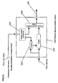
- Figure 3 is a schematic view showing an example of
applying the DTCP scheme to a two-storied house using
EthernetTR.
- Figure 4 is a block diagram of a packets sending/receiving
apparatus according to Embodiment 1 of the
present invention.
- Figure 5 is a schematic diagram showing an exemplary
packets format when packets is transmitted using MEPG-TS,
and then a frame is produced for transmission.
- Figure 6 is a schematic view for illustrating a
protocol stack according to Embodiment 1 of the present
invention.
- Figure 7 is a block diagram of a packets sending/receiving
apparatus according to Embodiment 2 of the
present invention.
- Figure 8 is a block diagram of a packets sending/receiving
apparatus according to Embodiment 3 of the
present invention.
- Figure 9 is a schematic view for illustrating a
protocol stack according to Embodiment 3 of the present
invention.
- Figure 10 is a schematic view showing an example of
packets format when packets are produced using MPEG-TS, and
then a frame is produced for transmission.
- Figure 11 is a block diagram of a packets sending/receiving
apparatus according to Embodiment 4 of the
present invention.
- Figure 12 is a block diagram for illustrating
packetization means and packets reception means according
Embodiment 4 of the present invention.
- Figure 13 is a block diagram for illustrating
packetization means and packets reception means according
Embodiment 5 of the present invention.
- Figure 14 is a schematic view for illustrating a
protocol stack according to Embodiment 5.
- Figure 15 is a schematic view for illustrating an
example where the error correction scheme is a Reed-Solomon
scheme.
- Figure 16 is a schematic view for illustrating an
example where the error correction scheme is a parity scheme.
- Figure 17 is a block diagram of a packets sending/receiving
apparatus according to Embodiment 6.
- Figure 18 is a block diagram of a packets sending/receiving
apparatus according to another example of
Embodiment 6 of the present invention.
- Figure 19 is a block diagram of a packets sending
means according to Embodiment 7 of the present invention.
- Figure 20 is a schematic view for illustrating a
protocol stack of preferred data packets.
- Figure 21 is a schematic view for illustrating a
sending timing chart of preferred data packets and a general
data packets.
- Figure 22 is a block diagram showing packets sending
means according to a variation of Embodiment 7 of the present
invention.
- Figure 23 is a block diagram of packets sending means
according to Embodiment 8.
- Figure 24 is a block diagram of packets sending means
according to a variation of Embodiment 8 of the present
invention.
- Figure 25 is a block diagram of packets sending means
according to Embodiment 9.
- Figure 26 is a block diagram of preferred data
packetization means according to a variation of Embodiment
9 of the present invention.
- Figure 27 is a block diagram of preferred data
packetization means according to a variation of Embodiment
9 of the present invention.
- Figure 28 is a diagram showing packets structure when
error correction is in a Reed-Solomon scheme.
- Figure 29 is a diagram showing packets structure when
error correction is in a parity process scheme.
- Figure 30 is a block diagram of packets sending means
according to Embodiment 10 of the present invention.
- Figure 31 is a block diagram of preferred data
packetization means according to Embodiment 10 of the present
invention.
- Figure 32 is a block diagram of preferred data
packetization means according to Embodiment 11 of the present
invention.
- Figure 33 is a schematic view for illustrating a
switching timing for encryption.
- Figure 34 is a block diagram of preferred data
packetization means according to Embodiment 12 of the present
invention.
- Figure 35 is a block diagram of packets sending system
which is applied to IEEE 1394 stream transmission according
to Embodiment 13 of the present invention.
- Figure 36 is a block diagram showing packets sending
system applied to a transmission of SDI/SDTI/DVB-ASI stream
according to Embodiment 13 of the present invention.
- Figure 37 is a block diagram of packets sending/recelving
apparatus according to Embodiment 13.
- Figure 38 is a schematic view illustrating a
transmission of MPEG-TS via transmission media which conforms
to IEEE 1394 standard by using the DTCP scheme.
-
BEST MODE FOR CARRYING OUT THE INVENTION
-
In the following description of the present
specification, an apparatus which can send and receive
information including packets will be referred to as a
sending/receiving apparatus. Two sending/receiving apparatuses
communicate information with each other. Further,
in the following description of the present specification,
a sending/receiving apparatus for sending data (for example,
AV data) which is to be sent is referred to as a "sending
apparatus", and a sending/receiving apparatus for receiving
such data sent by the sending apparatus will be referred
to as a "receiving apparatus" for the sake of convenience.
-
First, an overview of a system to which the present
invention can be applied will be described for clarifying
the present invention.
-
Figure 1 is a diagram showing an exemplary system
to which the present invention can be applied.
-
A sending apparatus 101 sends data to a receiving
apparatus 103 via a router 102.
-
More specifically, sending/receiving condition
related information, authentification and key exchange
(hereinafter, also referred to as AKE) setting information,
input stream (data such as MPEG-TS) are input into the sending
apparatus
101, and communication is performed based on the
following
procedures 1 through 3.
- Procedure 1) Setting sending/receiving parameters:
- (1-1) Sets media access control (MAC) addresses
internet protocol (IP) addresses, transmission control
protocol/user datagram protocol (TCP/UDP) port numbers and
the like of the sending apparatus 101 and the receiving
apparatus 103.
- (1-2) Sets types and bands of signals to be sent.
The sending apparatus 101 and the receiving apparatus
103 function as quality of service (QoS) agents. The router
102 functions as a QoS manager. Setting related to a network
using IEEE 802.1Q (VLAN) standard is performed between the
QoS agents and the QoS managers.
- (1-3) Sets priorities between the IEEE 802. 1Q/p
standard.
- Procedure 2) Authentification and key exchange:
- (2-1) The sending apparatus 101 and the receiving
apparatus 103 authenticate each other and exchange keys to
each other. In this case, for example, the DTCP scheme may
be used.
- Procedure 3) Data transmission
- (3-1) Encrypted data (for example, MPEG-TS) is
transmitted from the sending apparatus 101 to the receiving
apparatus 103.
-
-
In Figure 1, MPEG-TS is input to the sending apparatus
101 as an input stream. However, the present invention is
not limited to this. The input stream may be, for example,
MPEG-TS stream such as MPEG1/2/4 (ISO/IEC 13818), streams
standardized with DV (IEC 61834, IEC 61883), SMPTE 314M
(DV-based), SMPTE 259M (SDI), SMPTE 305M (SDTI), SMPTE 292M
(HD-SDI) and the like.
-
Data to be sent from the sending apparatus 101 may
be common AV data. Furthermore, data of the present invention
may be files. When files are transferred as data, data can
be transmitted faster than real time under the conditions
that the data transfer rate is larger than normal reproduction
data rate from the relationship between the propagation delay
time between the sending apparatus 101 and the receiving
apparatus 103 and the processing abilities of the sending
apparatus 101 and the receiving apparatus 103.
-
Next, with reference to Figure 2, the authentification
and key exchange in the above-mentioned procedure
2 will be further described.
-
Figure 2 is a diagram for showing operations of the
sending apparatus and the receiving apparatus in the case
where the DTCP scheme is applied for authentification and
key exchange.
-
Herein, authentification and key exchange
(hereinafter, also referred to as AKE) which conform to the
DTCP scheme are performed. In such a case, the sending
apparatus 101 is also referred to as an AKE source and the
receiving apparatus 103 is also referred to as an AKE sink.
-
The sending apparatus 101 and the receiving apparatus
103 are connected by an IP network.
-
First, protection mode information of data including
copy protection information of data is sent from the sending
apparatus 101 to the receiving apparatus 103. Herein, the
sending apparatus 101 may send encryption data at the same
time.
-
The receiving apparatus 103 analyzes the copy
protection information of the data and determines the
authentification scheme to be used to send authentification
request to the sending apparatus 101. By performing such
operations, the sending apparatus 101 and the receiving
apparatus 103 share the authentification key.
-
Next, the sending apparatus 101 encrypts exchange
keys using the authentification key to produce encryption
exchange key. Then, the sending apparatus 101 sends the
encryption exchange key to the receiving apparatus 103. The
receiving apparatus 103 uses the authentification key which
it shares with the sending apparatus 101 to decode the
encryption exchange key and produces the exchange key.
-
Then, the sending apparatus 101 produces key change
information which changes over time for changing the
encryption key in terms of time. Herein, the key change
information is also referred to as seed information. The
sending apparatus 101 sends the key change information to
the receiving apparatus 103.
-
The sending apparatus 101 produces an encryption key
using the exchange key and the key change information and
encrypts data (for example, MPEG-TS) by encryption means
using the encryption key to produce encryption data. Then,
the sending apparatus 101 sends the encryption data to the
receiving apparatus 103.
-
The receiving apparatus 103 produces an encryption
key using the key exchange information and the exchange key.
The receiving apparatus 103 decodes the encryption data using
the encryption key. In the receiving apparatus 103, the
encryption key is also referred to as a decode key.
-
Thereafter, the sending apparatus 101 and the
receiving apparatus 103 may confirm the key change information
of each other at any time.
-
Figure 3 is a schematic view showing an example of
applying the DTCP scheme to a two-storied house using
EthernetTR.
-
A network structure 301 for the first floor includes
a router 303. The router 303 is provided on the first floor.
The network structure 301 is connected to Internet via a
fiber to the home (FTTH) of 100 Mbps.
-
A network structure 302 for the second floor includes
a switching hub 304. The switching hub 304 is provided on
the second floor.
-
The router 303 is connected to the switching hub 304
via a network 305. In this way, the network structure 301
for the first floor is connected to the network structure
302 for the second floor. In this example, the network 305
is EthernetTR network for connecting the router 303 and the
switching hub 304. The router 303 also functions as a
switching hub.
-
The data rate of the EthernetTR network for the entire
house is 100 Mbps.
-
In the network structure 301 for the first floor,
a television (TV), a personal computer (PC), and Digital
versatile disc (DVD) recorder are connected to the router
303 by EthernetTR of 100 Mbps. Further, an air conditioner
and a refrigerator are connected by ECHONET.
-
In network structure 302 for the second floor, a
television (TV), a personal computer (PC), and Digital
versatile disc (DVD) recorder are connected to the switching
hub 304 by EthernetTR of 100 Mbps. Further, an air conditioner
is connected by ECHONET. ECHONET is a transmission scheme
developed in "ECHONET CONSORTIUM"
(http://www.echonet.gr.jp/).
-
In the example shown in Figure 3, the personal
computers (PCs), the DVD recorder, the router 303, and the
switching hub 304 support IEEE 802.1Q standard (VLAN). Thus,
data rates at all the ports are the same (for example, 100
Mbps). As long as the total data rate being output from a
specific output port does not exceed a standard value or
and effective value of an output port of the port in the
router 303 and the switching hub 304, data input from an
input port is not lost at the router 303 or the switching
hub 304 and is all output from an output port.
-
For example, even when data is input via eight input
ports at the same time, if outputs ports for the data are
different, the data do not conflict with each other in a
buffer provided inside the router 303 or the switching hub
304, and are switched and output from output ports. Data
input from the input ports are all output from the output
ports without a dropping packet.
-
In the example shown in Figure 3, the data rate of
the entire EthernetTR in the house is 100 Mbps and the data
rate of the network 305 between the first floor and the second
floor is also 100 Mbps. When a plurality of data flow between
equipment on the first floor and equipment on the second
floor, the total data rate flows on the network 305 may exceed
100 Mbps if there is no limit on the data rate for each of
the data. A data stream which requires real-time
transmission such as video application of MPEG-TS may be
interrupted.
-
In this case, it is necessary to perform priority
control with respect to the transmission data in order not
to interrupt a data stream which requires real-time
transmission. It becomes possible not to interrupt a data
stream which requires real-time transmission by introducing
a speed limit mechanism for stream transmission and file
transfer, which will be described later, not only to a terminal,
but also to the router 303 and the switching hub 304.
-
For instance, if a higher priority is given to
transmission of MPEG-TS data which requires real-time
transmission than to transmission of file data, it becomes
possible to transfer file between the PC at the first floor
and the PC at the second floor and encrypt MPEG-TS data and
transmit on a real-time basis between the DVD recorder, PC,
or TV at the first floor and the DVD recorder, PC, or TV
at the second floor at the same time.
-
The transmission speed limit mechanism at the router
303 or the switching hub 304 can be realized by data flow
control. More specifically, data with high priority and data
with low priority are compared at input data queue means
of the router 303 or the switching hub 304. Buffer control
rules used for priority control scheme include: a round robin
scheme; fluid fair scheduling scheme; weighting fair
scheduling scheme; self-synchronization fair scheduling;
WFFQ scheme; virtual clock scheduling scheme; classifying
scheduling scheme; and the like. The details of the
scheduling schemes are described in, for example, Iwao Toda,
"Nettowaku QoS Gi jutu (Network QoS Technique)", May 25, 2001
(First edition), Ohmsha Ltd., Chapter 12.
(Embodiment 1)
-
Figure 4 is a block diagram of a packets sending/receiving
apparatus 401 according to Embodiment 1 of
the present invention.
-
The packets sending/receiving apparatus 401
performs authentification and key exchange which conform
to the DTCP scheme to send and receive packets. In this
example, it is assumed that the packets sending/receiving
apparatus 401 send packets to another packet sending/receiving
apparatus having similar functions as the
packets sending/receiving apparatus 401 and receives packets
from such packets sending/receiving apparatus. Thus, the
packets sending/receiving apparatus 401 sends sending
packets to the destination of the sending packets and receives
reception packets from the source of the reception packets.
-
The packets sending/receiving apparatus 401 includes:
authentification/key exchange means (hereinafter,
also referred to as AKE means) 402 for producing an encryption
key and a decoding key; encryption means 406 for producing
encrypted sending data by encrypting sending data using the
encryption key; sending condition setting management means
404 for producing sending condition setting information for
setting sending conditions for set packets using at least
one of sending conditions related information, sending/receiving
management information, and receiving
condition setting information; packetization means 403 for
producing sending packets; receiving condition setting
management means 408 for producing receiving condition
setting information for setting receiving conditions of
reception packets using at least one of receiving condition
related information and packet receiving information;
packets reception means 405 for receiving reception packets,
which extracts reception data included in the reception
packets from the reception packets using the receiving
condition setting information, produces packets receiving
information from the reception packets, and outputs the
packets receiving information to the authentification/key
exchange means or the receiving condition setting management
means 408; and decoding means 407 for decoding the reception
data using the decoding key.
-
The packets sending/receiving apparatus 401 further
includes framing means 409 for producing sending frames using
the sending packets and frame reception means 410 for
receiving reception frames. This allows the packets
sending/receiving apparatus 401 to function as a sending
apparatus for sending the sending frames including the sending
packets and as well as a receiving apparatus for receiving
the reception frames including the reception packets.
-
Hereinafter, an example where the packets sending/receiving
apparatus 401 sends the sending frames using
TCP/IP or UDP/IP and the like will be described.
-
The sending condition related information, the
sending/receiving management information, and the receiving
condition setting information are input to the sending
condition setting management means 404.
-
The sending condition related information include,
for example, the type of the sending data, information on
an address to be sent orport number, path information (routing
information) used for sending, a band of the sending data,
and a priority for sending the sending data.
-
The sending/receiving management information
includes equipment management control data in a sending
apparatus (local) and a receiving apparatus (remote).
-
More specifically, the sending management information
includes equipment management control data such,
as media access control address or location information in
the sending apparatus (local) and the receiving apparatus
(remote). The location information is information with an
area specified by a region code, address, postal code, or
longitude and latitude. By using the location information,
it becomes possible to limit the area of sending equipment
and receiving equipment for authentification. Further, it
is also possible to limit authentification range by permitting
authentification when propagation time of the packets for
one-way or round trip between the sending apparatus and the
receiving apparatus is shorter than the predetermined limit
time. For example, the authentification range can be limit
by permitting authentification only when round trip time
(RTT) is 1 msec or shorter in IP connection of Ethernet scheme.
Further, when a plurality of transmission media, for example,
a wireless scheme such as 802.11a standard or 802.11b standard
and Ethernet standard are combined, authentification may
be permitted by setting RTTs which respectively correspond
to propagation delay properties of the transmission media.
Such times may be measured by commands specific to AKE, or
may be realized by including a time stamp or location
information in packets addition information, as will be
described with reference to Figure 5.
-
Further, if there is a wireless transmission zone
in a sending/receiving zone between the sending apparatus
and the receiving apparatus, it is possible to prevent a
third party from reading data due to data leakage in wireless
the transmission zone by permitting authentification after
performing encryption and scrambling of data to confirm that
it is in a transmission mode.
-
The receiving condition setting information includes
information for feeding back a reception state of
the receiving apparatus from the receiving apparatus to the
sending apparatus. The information is input from the
receiving condition setting management means 408 to the
sending condition setting management means 404.
-
The sending condition setting management means 404
produces sending condition setting information using at least
one of the sending condition related information, sending/receiving
management information and receiving condition
related information. The sending condition related
information includes at least one of location information
of the destination of the sending packets and location
information of source of received packets.
-
Using the sending condition setting information
produced in the sending condition setting management means
404, header, payload and the like are set in the packetization
means 403 and the framing means 409. The sending condition
setting management means 404 also outputs the sending
condition setting information the packetization means 403
and packets addition information producing means 411 included
in the packetization means 403.
-
To the AKE means 402, authentification and key
exchange setting information (hereinafter, also referred
to as AKE information) is input. From the AKE means 402,
authentification and key exchange related information
related to the AKE setting information (hereinafter, also
referred to as AKE related information) is input to the packets
addition information producing means 411. The authentification
and key exchange related information includes,
for example, copy protection information indicating encryption
state of encryption sending data at the time of
transmission and encryption key change information.
-
For example, MPEG-TS is input as an input stream to
the encryption means 406. The encryption means 406 takes
a part of MPEG-TS as the sending data and encrypt the sending
data using the encryption key produced at the AKE means 402
to produce the encryption sending data. The encryption
sending data is output from the encryption means 406 to the
packetization means 403.
-
The packetization means 403 produces sending packets
by using the encryption sending data based on sending
condition setting information produced in the sending
condition setting management means 404.
-
The packetization means 403 includes the packets
addition information producing means 411. The packet
addition information producing means 411 produces packets
addition information using at least one of sending condition
setting information and authentification and key exchange
related information.
-
The packetization means 403 converts the encryption
sending data into a predetermined size and may add internet
protocol (IP) header defined as IPv4 or IPv6 in IETF, add
information indicating that it is preferred packets in a
service type field in the IPv4 header or a type of service
(TOS) field within the service type field, or add information
indicating that it is preferred packets in a priority field
of the IPv6 header.
-
The packets additional information produced at the
packets addition information producing means 411 is input
to the packetization means 403 and added to the encryption
sending data. More specifically, the packets addition
information is added to the encryption sending data as a
part of a header of TCP/IP or UDP/IP protocol, and sending
packets are produced.
-
To the sending packets, encryption mode information
is also added as copy control information of the DTCP scheme
in the AKE means 402.
-
To the sending packets, an MAC header is further added
in the framing means 409 to form an EthernetTR frame. The
EthernetTR frame is output from the framing means 409 to a
network as a sending frame.
-
The copy control information of the contents is
referred to as copy control information (CGI). The copy
protection information indicating encryption at the
transmission is referred to as encryption mode indicator
(EMI). In general, EMI is used with a protection mode equal
to or stronger than that of CGI.
-
Next, an example in which the packets sending/receiving
apparatus 401 receives a reception frame will
be described.
-
The frame reception means 410 receives a reception
frame via the network.
-
The frame reception means 410 extracts an MAC header
included in the reception frame and performs filtering based
on the extracted MAC header. Then, the frame reception means
410 outputs IP packets obtained by filtering to the packets
reception means 405.
-
In the packets reception means 405, filtering is
performed by identifying an IP packets header of the IP packets
to produce packets reception information. AKE information
obtained as packets reception information by filtering is
input to packets addition information extraction means 412
included in the packets reception means 405. The packets
addition information extraction means 412 extracts packets
addition information from the reception packets. The
extracted packets addition information is output to the AKE
means 402.
-
In this way, the AKE means of the sending apparatus
and the AKE means of the receiving apparatus can be connected
to each other on one-on-one basis. Thus, they can exchange
messages to with each other via a communication protocol.
-
The AKE means 402 permits authentification when the
location information of the packets sending/receiving
apparatus 401 and the location information of the destination
of the sending packets or the location information of the
source of the reception packets match the predetermined
condition.
-
The AKE means 402 permits authentification when the
propagation time in one way or a round trip from the packets
sending/receiving apparatus 401 to the destination of the
sending packets or the source of the reception packets is
shorter than the predetermined limit time is shorter between
the packets sending/receiving apparatus 401 and the
destination of the sending packets or the source of the
reception packets.
-
Alternatively, when there is a wireless transmission
zone in the sending/receiving zone between the packets
sending/receiving apparatus 401 and the destination of the
sending packets or the source of the reception packets, the
AKE means 402 may permit authentification when it is confirmed
that it is in a mode of scrambling data for transmission
in the wireless transmission zone.
-
Therefore, authentification and key exchange can be
performed in accordance with setting procedure of two AKE
means.
-
After the authentification and key exchange are
approved between packets sending/receiving apparatus which
functions as a sending apparatus and packets sending/receiving
apparatus which functions as a receiving
apparatus, the sending apparatus sends encrypted AV data.
-
In the receiving apparatus, MEPG-TS data is input
to the encryption means 406. The encryption means 406
encrypts the MEPG-TS data to produce encrypted MEPG-TS data.
The encrypted MEPG-TS data is input to the packetization
means 403. A header of TCP/IP protocol is added in the
packetization means 403 to produce sending packets.
-
In the framing means 409, an MAC header is further
added to the sending packets using 802.1Q (VLAN) scheme to
convert into EthernetTR frame and to produce sending frames.
The sending frames produced as such are output to the network.
-
By setting priority (user priority) in tag control
information (TCI) in the MAC header, priority of network
transmission can be made higher than that of general data.
-
In the receiving apparatus, a signal input from the
network is filtered based on the MAC header in the frame
reception means 410, and is input to the packets reception
means 405 as IP packets. The IP packets are filtered in the
packets reception means 405 by identifying a packets header
or the like, and is input to the decoding means 407. Then,
decoded MEPG-TS is output.
-
To the sending condition setting management means
404, information for feeding back the reception state to
the sending apparatus from the receiving condition setting
management means 408 as receiving condition setting information
is input. The sending condition setting management
means 404 produces sending condition setting
information based on this information. Based on the sending
condition setting information, the header and the payload
produced in the packetization means 403 and the framing means
409 are set.
-
Figure 5 is a schematic diagram showing an exemplary
packets format when packets are transmitted using MEPG-TS,
and further, a frame is produced and transmitted. In this
example, MEPG-TS conforms to ISO/IBC 13818. MEPG-TS may be
a signal format based on ARIB standard, ARIB TR-B14, ARIB
TR-B15, or ARIB STD-B21.
-
MEPG-TS to be input as an input stream is segmented
in every 188 bytes. A time code (TC) of 6 bytes is added
to the MEPG-TS of 188 bytes to form a unit of 194 bytes.
In this example, TC includes a time stamp of 42 bits and
a base clock ID (BCID) of 6 bits.
-
BCID can represent frequency information of the time
stamp.
-
- (Case 1) When BCID is 0x00, there is no frequency
information of time stamp;
- (Case 2) When BCID is 0z01, the frequency information
of the time stamp is 27 MHz (system clock frequency of MPEG2) ;
- (Case 3) When BCID is 0x02, the frequency information
of the time stamp is 90 kHz (clock frequency used with MPEG1);
- (Case 4) When BCID is 0x03, the frequency information
of the time stamp is 24.576 MHz (clock frequency used with
IEEE 1394); and
- (Case 5) When BCID is 0x04, the frequency information
of the time stamp is 100 MHz (frequency used in EthernetTR).
-
-
Two units of data of 194 bytes are combined and
encrypted to produce encryption data. Then, packets
addition information of 7 bytes is added to the encryption
data. In this way, a payload of RTP protocol is formed.
-
In this example, the packets addition information
includes encryption mode indicator (EMI) of 2 bits, odd/even
(O/E) of 1 bit, reserved data of 13 bits and a time stamp
or location information of 40 bits. EMI and O/E are defined
by the DTCP scheme. Instead of O/E, seed information (No)
of DTCP may be used.
-
The packets addition information producingmeans 411
(see Figure 4) uses the AKE related information to produce
EMI and O/E.
-
The time stamp or the location information is produced
in the packets addition information producing means 411 (see
Figure 4) using sending condition setting information, and
is located following the reserved data. The time stamp or
the location information may also be located between the
O/E and the reserved data.
-
The location information is information with an area
specified by a region code, address, postal code, or longitude
and latitude.
-
In this example, the packets addition information
is 7 bytes. However, the packets addition information is
not limited to 7 bytes.
-
The packets addition information may not include the
time stamp or the location information. In such a case, the
packets addition information becomes 2 bytes.
-
When the packets addition information of 7 bytes is
added to the encryption data, the payload of the RTP protocol
is formed. When a RTP header is added as a header, the RTP
protocol is formed.
-
The RTP protocol is a payload of TCP packets or UDP
packets. When a TCP header or a UDP header is added, the
TCP packets or the UDP packets are formed.
-
The TCP packets or the UDP packets are a payload of
IP packets. When an IP header is added as a header, the ID
packets are produced. In this example, the IP header is
defined as Ipv4 or Ipv6 with IETF.
-
Furthermore, the IP packets are a payload of a MAC
frame. When an Ethernet header is added as a header, Ethernet
packets are produced.
-
As the EthernetTR header, both a standard EthernetTR
header and a EthernetTR header extended with IEEE 802.1Q (VLAN)
are applicable as shown in Figure 5.
-
A standard Ethernet header is 14 bytes, and includes
destination address (DA) of 6 bytes, source address (SA)
of 6 bytes, and information indicating length/type of 2 bytes.
-
An Ethernet header extended with 802.1Q is 18 bytes.
The Ethernet header extended with 802.1Q is different from
a standard Ethernet header on the point that 802.1Q extended
part of 4 bytes is provided between the SA and the information
indicating the length/type.
-
The 802.1Q extended part includes tag control ID
(TPID) of 2 bytes and tag control information (TCI) of 2
bytes which indicates VLAN priority.
-
TCI includes priority (user priority) of 3 bits,
canonical format indicator (CFI) of 1 bit and VLAN Identifier
(VID) of 12 bits.
-
How to use priority is defined by ISO/IEC 15802-3.
With a flag of the priority, priority of the EthernetTR frame
can be set.
-
Figure 6 is a schematic view for illustrating a
protocol stack according to Embodiment 1 of the present
invention.
-
On the left of side of Figure 6, a hierarchy of open
systems interconnection (OSI) is shown. The hierarchy
includes a link layer, a network layer, a transmission layer,
and an application layer in this order from the bottom.
-
First, encryption data is sent from the sending
apparatus to the receiving apparatus via a data port, and
AKE related information is sent via an AKE port.
-
In the receiving apparatus, copy protection information
of data is analyzed and an authentification scheme
is determined. Then, authentification request is sent to
the sending apparatus.
-
Next, in the sending apparatus, a random number is
generated. The random number is input into a predetermined
function to produce an exchange key. When information of
the exchange key is input into a predetermined function,
an authentification key is produced.
-
In the receiving apparatus, a predetermined process
is performed to produce the authentification key. In this
way, the sending apparatus and the receiving apparatus share
the authentification key.
-
In this example, information used for encryption is
information produced by combining one or more of information
unique to the sending apparatus (for example, equipment ID,
authentification information of the equipment, MAC address,
and the like), secret key, public key, information provided
from outside. Secure encryption can be achieved by using
encryption scheme with a high encryption strength such as
DES scheme or AES scheme.
-
Next, the sending apparatus encrypts the exchange
key using the authentification key to produce an encryption
exchange key and outputs the encryption exchange key to the
receiving apparatus. The receiving apparatus uses the
authentification key to decode the encryption exchange key
to the exchange key. Further, the exchange key and initial
key update information are input into a predetermined function
and produces the encryption key (decode key).
-
Further, the receiving apparatus produces key update
information which changes over time for changing the
encryption key over time, and send the key update information
to the receiving apparatus.
-
In the sending apparatus, MEPG-TS data, which is
contents data, is encrypted with the encryption key, and
encryption data is produced. The encryption data becomes
payload of TCP (or UDP) packets as AV data with the
above-mentioned EMI and O/E, and the TCP (or UDP) packets
are produced. Further, the TCP (or UDP) packets are used
as a payload of IP packets, and the IP packets are produced.
The IP packets are used as a payload of a MAC frame, and
the EthernetTR MAC frame is produced.
-
MAC can be applied not only to IEEE 802.3 standard,
which is a standard for EthernetTR, but also to MAC of IEEE
802.11 standard, which is a standard for the wireless LAN.
-
EthernetTR MAC frame is transmitted from the sending
apparatus to the receiving apparatus over EthernetTR. The
receiving apparatus produces the encryption key (decode key)
in accordance with a predetermined procedure. Then, the IP
packets are filtered from the received EthernetTR MAC frame.
Further, the TCP (or UDP) packets are extracted from the
IP packets. Then, AV data is extracted from the TCP (or UDP)
packets. By using the exchange key and the encryption key
(decode key) produced using the key change information, data
(MEPG-TS) is decoded.
-
Preferably, the timing information indicating
timing for the AKE means 402 to update the decode key is
added to sending packets. In such a case, the timing for
the AKE means 402 to update the decode key may be notified
by changing a TCP port number or UDP port number of the sending
packets.
-
When the sending packets use HTTP, the timing for
the AKE means 402 to update the decode key may be updated
for every HTTP request, or may be changed for every constant
amount of data.
-
Alternatively, in the case where the sending packets
use RTP, the timing for the AKE means 402 to update the decode
key may be updated within a predetermined period (f or example,
60 seconds).
-
As described above, it is possible to encrypt data
such as MEPG-TS in the sending apparatus, transmit the IP
packets via the network with HTTP/TCP/IP or RTP/UDP/IP, and
decode to original data in the receiving apparatus. If the
above-mentioned O/E or seed information (Nc) is updated in
accordance with a certain rule, for example, for every HTTP
request, or for every constant amount of AV data (for example,
IMB), or within a predetermined time, security can be further
improved.
-
Now, with reference to Figure 3 again, how stream
transmission and file transfer can become compatible by
changing a network topology using the switching hub will
be described.
-
For example, by extending the data rate of the network
305 between the first floor and the second floor from 100
Mbps to 1 Gbps, it becomes possible to transfer a file between
the PC of the first floor to the PC of the second floor,
and to encrypt and transmit in real time MEPG-TS between
the DVD recorder, PC or TV of the first floor and DVD recorder,
PC or TV of the second floor at the same time.
-
For example, a commercially available switching hub
having eight ports of 100 Mbps and one port of 1Gbps is used.
The port of 1 Gbps is connected to the network 305 which
connects the network structure 301 for the first floor and
the network structure 302 for the second floor. AV equipment
such as TV are connected to the remaining eight ports of
100 Mbps. Since there are eight 100 Mbps ports, even when
data is respectively input to the eight ports at maximum
of 100 Mbps and output from one port, the total data rate
of the input ports is 800 Mbps (100 Mbps×8ch). This value
is smaller than 1Gbps. Thus, data input from the eight input
ports are not lost in the switching hub, and is all output
from the output port.
-
Therefore, it is possible to transmit all the data
to be output from AV equipment on the first floor to the
second floor via the network 305. It is also possible to
transmit all the data to be output from AV equipment on the
second floor to the first floor via the network 305.
-
By using the switching hub as described above,
real-time transmission of data and file transfer can be
performed at the same time.
(Embodiment 2)
-
Figure 7 is a block diagram of a packets sending/receiving
apparatus 401A according to Embodiment 2 of
the present invention.
-
The packets sending/receiving apparatus 401A has a
similar structure as the packets sending/receiving apparatus
401 described with reference to Figure 4 in Embodiment 1
except for that it further includes sending queue control
means 601, first queue means 602, and second queue means
603. In the following description, the sending queue control
means 601, the first queue means 602 and the second queue
means 603 will be mainly described in order to simplify the
description.
-
The packetization means 403 performs a TCP/IP
protocol process to general data to produce first packets
group, and outputs the first packet group to the first queue
means 602. In this example, general data is, for example,
sending condition setting information or AKE related
information.
-
The first queuemeans 602 temporarily stores the first
packets.
-
The packetization means 403 again performs a TCP/IP
protocol process to the encryption sending data produced
at the encryption means 406 to produce second packets, and
outputs the second packets to the second queue means 603.
-
The second queue means 603 temporarily stores the
second packets.
-
The packetization means 403 uses general data for
producing first packets group, while it uses the encryption
data, which is contents data, to produce second packets
group.
-
The sending queue control means 602 controls that
which packets are to be output preferentially based on the
sending condition setting information when the packets are
temporarily stored in the first queue means 602 and the second
queue means 603.
-
Specifically, the sending queue control means 601
controls which of the first packets stored in the first queue
means and the second packets stored in the second queue means
is to be sent by using at least one of the information regarding
a sending path of the first packets or the second packets,
information regarding a bandwidth required for sending the
first packets or the second packets, information regarding
a delay from sending of the sending packets from the arrival,
and information regarding a priority of the first packets
or the second packets.
-
In normal state, the sending queue control means 602
controls the first queue means 602 and the second queue means
603 so as to output contents data such as MPEG-TS preferentially
over general data. In other words, the sending
queue control means 602 handles the encryption sending data,
which is contents data, as preferred data which is given
a priority over general data.
-
The preferred data has at least one of data stream
formats such as an uncompressed SD format signal defined
by SMPTE 259M standard, an uncompressed HD format defined
by SMPTE 292 standard, a transmission stream format of DV
or MPEG-TS by IEEE 1394 defined by IEC 61883, MPEG-TS format
by DVB-ASI defined by DVB standard A010, MPEG-PS format,
MPEG-ES format, and MPEG-PES format.
-
The sending queue control means 601 may any one of
control scheme such as RSVP scheme described with IETF RFC2205,
RFC2208, RFC2209, Intserv scheme described with IETF RFC2210,
RFC2211, 2212, RFC2215, and Diffserv scheme described with
IETF RFC2474, RFC2475, RFC2597, RFC2598.
-
The framing means 409 uses the first packets or the
second packets respectively output from the first queue means
602 and the second queue means 603 to produce a sending frame,
and outputs the sending frame to the network.
-
The sending queue control means 601 may control the
first queue means and the second queue means so as to average
a period between the first packets to be sent from the first
queue means 602 and the second packets to be sent from the
second queue means 603.
-
In general, when MEPG-TS is transmitted from the
sending apparatus to the receiving apparatus with a low delay,
overflow is more likely to occur since a buffer for MEPG-TS
is small.
-
In the sending apparatus, when a buffer for MEPG-TS
(for example, a buffer of the second queue means 603) nearly
overflows, or it turn out that a buffer for MEPG-TS in the
receiving apparatus nearly underflow with reference to
information fed back from the receiving apparatus, such a
crash of a buffer can be avoided by further increasing the
priority of the second queue means 603 adaptively so as to
preferentially output data of MEPG-TS.
-
When the sending apparatus remotely operates the
receiving apparatus, the priority of the first queue means
602 may be increased adaptively in the sending apparatus
in order to increase control response such as reproduction
and stop of the receiving apparatus. However, in such a case,
the buffer for the MEPG-TS may overflow or underflow.
-
Accordingly, for the sending apparatus to remotely
operate the receiving apparatus so as to avoid overflow and
underflow of the buffer, and increase the speed of control
response such as reproduction and stop of the receiving
apparatus, a rapid control response can be realized by
outputting packets for remotely controlling the receiving
apparatus directly from the packetization means 403 to the
framing means 409 without passing through the queue means.
Alternatively, a rapid control response can be realized by
newly providing third queue means for packets for remotely
controlling the receiving apparatus.
-
The operation of the receiving apparatus is similar
to that in Embodiment 1.
-
Preferably, the sending queue control means 601
controls the first queue means 602 and the second queue means
603 such that the data rate of the second packets group does
not become smaller than a predetermined value. Further, it
is preferable that the sending queue control means 601
controls the first queue means 602 and the second queue means
603 such that storage time in the second queue means 603
is always smaller than the predetermined value.
(Embodiment 3)
-
Embodiment 3 will be described.
-
Figure 8 is a block diagram of a packets sending/receiving
apparatus 401B according to Embodiment 3 of
the present invention.
-
The packets sending/receiving apparatus 401B has a
similar structure as the packets sending/receiving apparatus
401A described with reference to Figure 7 in Embodiment 2
except for that the packetization means 403 includes first
packetization means 701 and second packetization means 702,
and the packets reception means 405 includes a first packets
reception means 703 and second packets reception means 704.
In the following description, the first packetization means
701, second packetization means 702, the first packets
reception means 703 and the second packets reception means
704 will be mainly described in order to simplify the
description.
-
First, how the receiving/sending apparatus 401B send
a sending frame will be described.
-
The first packetization means 701 includes a
processor, for example. To the first packetization means
701, the sending condition setting information and the AKE
related information produced at the sending condition setting
management means 404 are input. The first packetization
means 701 produces first packets by performing a TCP/IP
protocol process on the sending condition setting information
and the AKE related information with a software process using
a processor to produce first packets. The first packetization
means 701 outputs the first packets to the first
queue means 602.
-
The first packetization means 701 adds at least one
header from RTCP, RTSP, HTTP, TCP, UDP, and IP, which are
data process protocol defined by the IETF document.
-
To the second packetization means 702, the encryption
sending data, which is sending data such as MPEG-TS encrypted
by the encryption means 406, is input. The AKE related
information may be input to the second packetization means
702. The AKE related information is, for example, copy
control information, encryption update information, and the
like.
-
The second packetization means 702 produces second
packets by performing UDP/IP protocol process on the
encryption sending data with a hardware process. The second
packetization means 702 outputs the second packets to the
second queue means 603.
-
The second packetization means 702 adds sequence
number, or at least one header from RTP, UDP, HTTP, TCP,
IP, which are data process protocols defined in the IETF
document to the data.
-
As in Embodiment 2 described above, the sending queue
control means 601 controls that which of the packets in the
first queue means 602 and the second queue means 603 is to
be output when packets are temporarily stored in both the
first queue means 602 and the second queue means 603.
-
How the sending/receiving apparatus 401B receives
a reception frame will now be described.
-
The frame reception means 410 receives a reception
frame via the network.
-
The frame reception means 410 filters IP packets from
the reception frame based on the MAC header.
-
When the IP packets is the same packets as the first
packets produced at the first packetization means 701, the
IP packets are input to the first packetization means 701.
When the IP packets are the same packets as the second packets
produced at the second packetization means 702, the IP packets
are input to the second packetization means 704.
-
In the first packets reception means 703, a reception
process of the TCP/IP protocol is performed with a software
process using a processor. The packets reception information
produced by the process is output to the AKE means
402 or the reception condition setting management means 408.
-
In the second packets reception means 704, a reception
process of UDP/IP protocol is performed with a hardware
process. Reception data extracted by the process is output
to the decoding means 407. The decoding means 407 decodes
encryption of the reception data.
-
Next, the above-mentioned procedure will be further
explained in detail using a protocol stack of Figure 9.
-
Figure 9 is a schematic view for illustrating a
protocol stack according to Embodiment 3 of the present
invention.
-
The protocol stack shown in Figure 9 has a similar
structure as the protocol stack described with reference
to Figure 6 except for the point that a transmission layer
of AV data such as MPEG-TS is UDP. Thus, in the following
description, the point that the transmission layer is UDP
will be described.
-
In the sending apparatus, sending data (for example,
MPEG-TS), which is contents, is encrypted using encryption
key Kc to produce encryption sending data. The encryption
sending data becomes a payload of UDP packets by a hardware
as AV data with the above-mentioned EMI and O/E. By adding
a UDP header, UDP packets are produced. Further, the UDP
packets are used as a payload of the IP packets, and the
IP packets are produced by adding an IP header.
-
The EMI and O/E may be transmitted from the sending
apparatus to the receiving apparatus by, for example,
producing other packets which are exclusively used. In such
a case, decoding of the encryption key becomes further
difficult. Eavesdropping and leakage of the contents can
be made more difficult. In the public network such as Internet,
it is possible to make eavesdropping and leakage of the
contents can be made more difficult by changing or sending
as other packets an encryption parameter of the AV data
transmitted real time.
-
As for the management control data, similarly to
example shown in Figure 6, the TCP packets are produced by
a software process and the IP packets are produced.
-
EthernetTR MAC frame is transmitted from the sending
apparatus to receiving apparatus over the EthernetTR. In
the receiving apparatus, an encryption key is produced in
accordance with a predetermined procedure. An IP packets
are filtered from the received EthernetTR MAC frame. Further,
UDP packets are extracted from the IP packets. Reception
data is extracted from UDP packets. Using the encryption
key Kc, reception data (for example, MPEG-TS) is decoded.
-
In a layer for processing the reception frame which
is a lower layer than a layer for processing encryption sending
data and general data, preferred data and general data can
be selected from communication protocol headers of the
reception packets included in the reception frame, and a
process for the preferred data and a process for the general
data can be performed independently.
-
Figure 10 is a schematic view showing an example of
packets format when packets are produced using MPEG-TS, and
a frame is produced for transmission. In this example,
MPEG-TS also conforms to ISO/IBC 13818.
-
The MPEG-TS input as an input stream is segmented
in every 188 bytes. A time code (TC) of 6 bytes may be added
to MPEG=TS of 188 bytes to form a unit of 194 bytes. In this
example, TC includes a time stamp of 42 bits and a base clock
ID (BCID) of 6 bits.
-
The BCID can represent frequency information of the
time stamp.
-
- (Case 1) When BCID is 0x00, there is no frequency
information of time stamp:
- (Case 2) When BCID is 0z01, the frequency information
of the time stamp is 27 MHz (system clock frequency of MPEG2);
- (Case 3) When BCID is 0x02, the frequency information
of the time stamp is 90 kHz (clock frequency used with MPEG1) ;
- (Case 4) When BCID is 0x03, the frequency information
of the time stamp is 24.576 MHz (clock frequency used with
IEEE 1394); and
- (Case 5) When BCID is 0x04, the frequency information
of the time stamp is 100 MHz (frequency used in EthernetTR).
-
-
Two units of data of 194 bytes are combined and
encrypted to produce encryption data. Then, packets
addition information of 2 bytes is added to the encryption
data. In this way, a payload of RTP protocol is formed.
-
In this example, the packets addition information
includes encryption mode indicator (EMI) of 2 bits, odd/even
(O/E) of 1 bit, reserved data of 13 bits and a time stamp
or location information of 40 bits. EMI and O/E are defined
by the DTCP scheme. Instead of O/E, seed information (Nc)
of DTCP may be used.
-
The packets addition information producing means 411
(see Figure 4) uses the AKE related information to produce
EMI and O/E.
-
The time stamp or the location information is produced
in the packets addition information producing means 411 (see
Figure 4) using sending condition setting information, and
is located following the reserved data. The time stamp or
the location information may also be located between the
O/E and the reserved data.
-
The location information is information with an area
specified by a region code, address, postal code, or longitude
and latitude.
-
In this example, the packets addition information
is 7 bytes. However, the packets addition information is
not limited to 7 bytes.
-
The packets addition information may not include the
time stamp or the location information. In such a case, the
packets addition information becomes 2 bytes.
-
When the packets addition information of 7 bytes is
added to the encryption data, the payload of the RTP protocol
is formed. When a RTP header is added as a header, the RTP
protocol is formed.
-
The RTP protocol is a payload of TCP packets or UDP
packets. When a TCP header or a UDP header is added, the
TCP packets or the UDP packets are formed.
-
The TCP packet or the UDP packet is a payload of an
IP packet. When an IP header is added as a header, the ID
packet is produced.
-
Furthermore, the IP packets are a payload of a MAC
frame. When an Ethernet header is added as a header, Ethernet
packets are produced.
-
As the EthernetTR header, both a standard EthernetTR
header and a EthernetTR header extended with IEEE 802.1Q (VLAN)
are applicable as shown in Figure 10.
-
A standard Ethernet header is 14 bytes, and includes
destination address (DA) of 6 bytes, source address (SA)
of 6 bytes, and information indicating length/type of 2 bytes.
-
An Ethernet header extended with 802.1Q is 18 bytes.
The Ethernet header extended with 802.1Q is different from
a standard Ethernet header on the point that 802.1Q extended
part of 4 bytes is provided between the SA and the information
indicating the length/type.
-
The 802.1Q extended part includes tag control ID
(TPID) of 2 bytes and tag control information (TCI) of 2
bytes which indicates VLAN priority.
-
TCI includes priority (user priority) of 3 bits,
canonical format indicator (CFI) of 1 bit and VLAN Identifier
(VID) of 12 bits.
-
How to use priority is defined by ISO/IEC 15802-3.
With a flag of the priority, priority of the EthernetTR frame
can be set.
-
In this way, sending data (for example, MPEG-TS) is
encrypted between the sending apparatus and the receiving
apparatus and real-time transmission becomes possible.
Further, since the second packetization means is formed with
a hardware, essentially, there is no un-sent sending packets
or un-received reception packets due to a software process.
Thus, all the preferred data packets are completely sent,
and transmission of high-quality image with a secured
real-time property becomes possible.
-
Further, general data is temporarily stored in a
buffer and intermittently transmitted while the preferred
data is being transmitted preferentially. The first
packetization means 701 may be formed of a reasonable
processor such as microcomputers.
-
Further, with a hardware process, an EthernetTR can
be received and the IP header of the third layer and the
UDP header of the fourth layer can be checked at the same
time in a reception process.
-
Packets of contents data (for example, MPEG-TS),
which are preferred data, and packets of general data are
separated, and a process of the packets of the contents data
is performed with a hardware. Thus, there is no un-received
reception frame and a high-quality reception with a real
time property secured can be performed.
-
By controlling the timing for sending packets, or
percentage of sending packets from two queue means by a
hardware instead of a software, it becomes possible to
completely control sending in a clock unit. In this way,
all the preferred packets can be completely sent and a
high-quality transmission with a real-time property secured
becomes possible. Since shaping of the output packets is
accurately performed in a clock unit, a high-quality
communication with a very small percentage of packets dropping
at a router in a first stage or a switching hub.
(Embodiment 4)
-
Figure 11 is a block diagram of a packets sending/receiving
apparatus 401C according to Embodiment 4 of
the present invention.
-
The packets sending/receiving apparatus 401C has a
similar structure as the packets sending/receiving apparatus
401B described with reference to Figure 8 in Embodiment 4
except for the point that AKE means 402 includes DTCP
information production means 1001, AKE command reception
process means 1002, AKE command sending process means 1003,
exchange key production means 1004, encryption key production
means 1005, encryption key change information production
means 1006, and decoding key production means 1007.
Therefore, in the following description, the DTCP information
production means 1001, the AKE command reception process
means 1002, the AKE command sending process means 1003, the
exchange key production means 1004, the encryption key
production means 1005, the encryption key change information
production means 1006, and the decoding key production means
1007 are mainly described.
-
In the packets sending/receiving
apparatus 401C,
encryption sending data is sent with the DTCP scheme in
accordance with the following steps. In this embodiment,
functions of both the source for sending packets and the
sink for receiving packets are described with reference to
packets sending/receiving
apparatus 401C. Please note that
this is for the sake of simplicity of the description, and
packets are sent and receiving in two different packets
sending/receiving apparatuses actually.
- (Step 1) Copy protection information representing
an encryption state of encryption sending data during
transmission is input to the DTCP information production
means 1001 as authentification and key exchange related
information.
- (Step 2) First, a request for sending data is
generated in the sending apparatus (source). The data
protection mode information (EMI) information is output from
the DTCP information production means 1001 to the first
packetization means 701. Sending packets are produced and
the sending packets are sent from the sending apparatus.
- (Step 3) The sending packets sent from the sending
apparatus is received as reception packets in the receiving
apparatus (sink). The AKE command reception process means
1002 analyzes copy protection information of the data received
from the first packets reception means 703, and determines
which of the authentification scheme, complete authentification
or limited authentification, is to be used. Then,
the AKE command reception process means 1002 sends an
authentification request through the AKE command sending
process means 1003.
- (Step 4) A predetermined process of the DTCP scheme
is performed between the receiving apparatus and the sending
apparatus is performed, and an authentification key is shared.
- (Step 5) Next, the sending apparatus sends an
encryption exchange key produced by encrypting an exchange
key using the authentification key in the AKE command sending
process means 1003 via the first packetization means 701.
In the receiving apparatus, an encryption exchange key is
extracted by the AKE command reception process means 1002
and decoded to an exchange key in the exchange key production
means 1004.
- (Step 6) In the sending apparatus, seed information
(O/E) which changes over time is produced in the encryption
key production means 1005 for changing an encryption key
over time. The seed information is tent to the receiving
apparatus via the DTCP information production means 1001
and the first packetization means 701.
- (Step 7) In the sending apparatus, an encryption key
is produced using the exchange key and the seed information
in the encryption key production means 1005. The encryption
means 406 encrypts sending data (for example, MPEG-TS) using
the encryption key and produces encryption sending data.
The encryption means 406 outputs the encryption sending data
to the second packetization means 702.
- (Step 8) In the receiving apparatus, the encryption
key change information production means 1006 receives seed
information from the first packets reception means 703. The
decoding key production means 1007 uses the seed information
and the exchange key of the exchange key production means
1004 to produce an encryption key (decoding key).
- (Step 9) In the receiving apparatus, the encryption
key (decoding key) is used to decode the encrypted data in
the decoding means 407.
- Figure 12 is a block diagram for illustrating packets
processes in the first packetization means 701 and the second
packetization means 702 included in the packetization means
403, and the first packets reception means 703 and the second
packets reception means 704 included in the packets reception
means 405.
-
-
In the first packetization means 701, processes for
forming the input data to an RTCP or RTSP protocol, a TCP
or UDP protocol, and an IP protocol is sequentially performed.
-
Further, when RTCP protocol (RFC1889) is used,
communication sate of the network such as effective bandwidth
and delay time of the network is sent from the receiving
apparatus to the sending apparatus. The sending apparatus
can adjust the quality of the data to be transmitted with
RTP in accordance with the communication state of the network
over which it has been sent and send the data.
-
The RTSP protocol (RFC2326) can send the control
command such as reproduction, stop, forward and the like.
It is also possible to reproduce data with the data being
downloaded from an AV file.
-
In the second packetization means 702, processes for
forming the input data into the RTP protocol, UDP protocol,
and the IP protocol are sequentially formed to produce IP
packets.
-
In the first packets reception means 703, a reception
process of the IP protocol, a reception process of the TCP
or UDP protocol, and a reception process of the RTCP or RTSP
protocol such as filtering are sequentially performed. Thus,
reception data included in the reception packets is extracted.
-
Further, in the second packets reception means 704,
a reception process of the IP protocol, a reception process
of the UDP protocol, and a reception process of the RTP protocol
such as filtering are sequentially performed to extract a
reception data included in the reception packets.
-
In this way, data (for example, MPEG-TS) is encrypted
based on the DTCP scheme between the sending apparatus and
the receiving apparatus and real-time transmission becomes
possible. Further, since the second packetization means is
formed with a hardware, essentially, there is no un-sent
sending packets or un-received reception packets due to a
software process. The first packetization means with a small
data amount may be formed of a reasonable processor such
as microcomputers.
-
Even when authentification between the receiving
apparatus and the receiving apparatus cannot be secured
because any of the predetermined conditions is not matched
due to some reason, a least one of certificate which the
sending apparatus or the receiving apparatus has previously
stored, information such as MAC address and biometric
information for specifying an individual such as fingerprint,
iris and the like may be used for performing authentification
between the sending apparatus and the receiving apparatus.
-
Again, with reference to Figure 11, in the case where
authentification is performed between the packets sending/receiving
apparatus 401C, and destination of the sending
packets or the sending source of the reception packets, the
AKE command reception process means 1002 of the authentification
and key exchange means 402 may function as verify
means for verifying the information stored in the storage
means and information regarding destination of the sending
packets or information regarding sending address of the
reception packets when the authentification is not secured
since the storage means for temporarily stores information
regarding the destination of the sending packets or the
sending source of the reception packets, the packets
sending/receiving apparatus, and the destination of the
sending packets and the sending source of the reception
packets do not match the predetermined conditions.
-
In this way, two equipment authentificated one
another within a household can be specifically authentificated
between remote places. Thus, transmission of data
contents and remote transmission of data contents between
the household and a remote place such as travel destination
become possible.
(Embodiment 5)
-
Figure 13 is a block diagram for illustrating packets
processes in the first packetization means 701 and the second
packetization means 702 included in the packetization means
403A, and the first packets reception means 703 and the second
packets reception means 704A included in the packets reception
means 405A.
-
The packetization means 403A and the packets
reception means 405A have similar structures as the
packetization means 403 and the packets reception means 405
described with reference to Figure 12 on the point that the
second packetization means 702 and the second packets
reception means 704A are different. Therefore, in the
following description, the second packetization means 702A
and the packets reception means 405 will be mainly described.
-
The second packetization means 702A performs error
correction process on the data to be input and sequentially
processes so as to form RTP protocol, UDP protocol, and IP
protocol to produce IP packets.
-
The second packets reception means 704A sequentially
performs a reception process of IP protocol, reception process
of UDP protocol, and reception process of RTP protocol such
as filtering, and further, an error correction code process.
Thus, error-corrected data is output.
-
Figure 14 is a schematic view for illustrating a
protocol stack according to Embodiment 5.
-
In the sending apparatus, an error correction code
is added to AV data (ECC encode), and passed to the UDP protocol.
In the receiving apparatus, data is received and error-corrected
with the UDP protocol process and becomes AV
data for upper layers.
-
Examples of error correction schemes will be
described with reference to Figures 15 and 16.
-
Figure 15 is a schematic view for illustrating an
example where the error correction scheme is a Reed-Solomon
scheme.
-
Figure 16 is a schematic view for illustrating an
example where the error correction scheme is a parity scheme.
-
In these examples, data (MPEG-TS) of two units is
input to an error correction interleave matrix. 2 bytes of
the sequence number are used for each row.
-
Then, packets addition information of two bytes, for
example, is used and the RTP header, UDP header, IP header,
EthernetTR header are further added to produce an EthernetTR
frame.
-
In this way, data (for example, MEPG-TS) can be
encrypted based on the DTCP scheme between the receiving
apparatus and the sending apparatus and an error correction
code is added, and can be transmitted in a real-time manner.
-
Further, since the second packetization means is
formed with a hardware, essentially, there is no un-sent
sending packets or un-raceived reception packets due to a
software process. The first packetization means with a small
data amount may be formed of a reasonable processor such
as microcomputers.
(Embodiment 6)
-
Figure 17 is a block diagram of a packets sending/receiving
apparatus 401D according to Embodiment 6.
-
The packets sending/receiving apparatus 401D has a
similar structure as the packets sending/receiving apparatus
401C described with reference to Figure 11 except for the
point that a receiving function of the reception data (for
example, AV data such as MPEG-TS) is omitted.
-
Figure 18 is a block diagram of a packets sending/receiving
apparatus 401E according to another example
of Embodiment 6 of the present invention.
-
The packets sending/receiving apparatus 401E has a
similar structure as the packets sending/receiving apparatus
401C described with reference to Figure 11 except for the
point that a sending function of the sending data (for example,
AV data such as MPEG-TS) is omitted.
-
Omitting the receiving function or the sending
function of data as such can be applied to all the packets
sending/receiving apparatuses described in Embodiments 1
through 5. Further, the present invention can also be applied
to equipment which performs only sending or reception. Thus,
it is possible to try to reduce the cost.
-
In the above-described Embodiments 1 through 6, when
packets are transmitted over a communication network where
the order of the packets are not secured, such as, a general
IP network, packets with the sequence number added may be
sent and the order may be secured using the sequence number
added to the packets in the receiving apparatus. The order
can be secured at the fourth layer or higher of OSI model,
in other words, with RTP protocol or video signal process.
-
The packets of the AV data which is subjected to a
hardware process and transmitted can be prevented from being
fragmented in the network. Specifically, in the sending
apparatus, the maximum size (MTU) not fragmented in the
communication network is previously checked and the packets
are transmitted with the packet size equal to or smaller
than the maximum size.
-
More specifically, the sending condition setting
management means 404 and the receiving condition setting
management means 408 detects the maximum transmission packet
size in a path from the sending destination of the sending
packet to the reception destination between sending and the
arrival of the sending frame. The maximum transmission
packet size information is used to produce sending condition
setting information or receiving condition setting management
means.
-
Alternatively, in the standard of RFC, it is defined
all the terminals should be capable of handling IP packets
of the size of 576 bytes. Thus, in most of network equipments
such as a router, fragmentation does not occur on the IP
packets having the size equal to or smaller than this. Thus,
it is enough if the packet size of the AV data to be subjected
to a hardware process in the sending apparatus is adjusted.
When fragmentation does not occur in packets of AV data to
be subjected to a hardware process in the sending apparatus,
if the received packets are fragmented, they can be all
processed as general packets. When the size exceeds the
maximum value of the IP packet of EthernetTR, fragmenting
in the sending apparatus is required. Accordingly, it is
needless to say that the size should be equal to or smaller
than the maximum size of the IP packet in order to prevent
the preferred packets from being fragmented.
-
When the percentage of fragmenting in the communication
network is very small, a flag of fragmenting
prohibition is added to IP header of the packets of the AV
data subjected to a hardware process in the sending apparatus
and transmitted and is sent. In this way, IP packet may be
dropped in the situation where the router should fragment
to alleviate a load of fragmenting process of the receiving
apparatus. In this case, very small number of packets is
lost, but communication quality can be compensated by
performing error correction or error retouch in the receiving
apparatus.
-
Further, in Embodiments 1 through 6, EthernetTR is
explained as a specific example of communication protocols.
However, the present invention is not limited to this.
-
Moreover, MPEG-TS is used as an example of video
signal process in Embodiments 1 through 6. However, the
present invention is not limited to this. As the input stream
of the present invention, any stream regarding video and
audio including MPEG-TS stream (ISO/IEC 13818) such as
MPEG1/2/4, and streams standardized by DV (IEC 61834, IEC
61883), DV (IEC 61834, IEC 61883), SMPTE 314M (DV-based),
SMPTE 259M (SMI), SMPTE 305M(SDTI), SMPTE 292M (HD-SDI) and
the like are applicable.
-
The data rate of the video and audio is not limited
to constant bit rate (CBR). It may be VBR. Furthermore,
not only video and audio but general real time data, and
any data as long as sent/received preferentially should not
be omitted from the present invention.
-
The data to be used in the present invention may be
a file. When the data is a file, it is also possible to transmit
data more rapidly than real time under certain conditions
based on the relationship between propagation delay time
between the sending apparatus and the receiving apparatus,
and a processing property of the sending apparatus and the
receiving apparatus.
-
Further, a contents transmission scheme which is
generally called streaming in the field of the Internet can
also be realized. In contents transmission of the streaming
scheme, contents data is transmitted with TCP/IP or UDP/IP
from the sending apparatus to the buffer of the receiving
apparatus via the network and the contents data is read out
at a relatively constant rate from the buffer of the receiving
apparatus, continuous data is reproduced in the receiving
apparatus.
-
Further, the present invention is also applicable
to GXF file format (SMPTE 360M) standardized by SMPTE
(www.smpte.org) and encryption transmission of a file which
conforms to a MXF file format which has been promoted to
be standardized.
(Embodiment 7)
-
Hereinafter, Embodiment 7 will be described.
-
Figure 19 is a block diagram of a packets sending
means 1101 according to Embodiment 7 of the present invention.
-
In this example, the packets sending means 1101
corresponds to the packetization means 403 and the framing
means 409 described with reference to Figure 4.
-
The packets sending means 1101 includes general data
input means 1102, packetization information input means 1104,
general data packetization means 1105, buffer means 1106,
valid data extraction means 1107, preferred data packetization
means 1109, packets sending order control means
1113, and a frame data sending means 1114.
-
In the packets sending means 1101, preferred data
is input from priority data input means 1103 to the valid
data extraction means 1107. The valid data extraction means
1107 removes invalid data component from the input preferred
data and extracts a valid payload, and inputs valid data
1108 to the preferred data packetization means 1109.
-
The preferred data packetization means 1109
corresponds to the second packetization means 702 of the
packets sending/receiving apparatus 401B described with
reference to Figure 8.
-
The packets sending order control means 1113
corresponds to sending queue means 601 of the packets
sending/receiving apparatus 401B described with reference
to Figure 8.
-
The process in the valid data extraction means 1107
includes buffering of data, data bit number conversion, clock
frequency conversion and the like.
-
Specifically, the preferred data stream may be SDTI
stream of SMPTE321M standard, or the valid data may be DIF
data of SMPTE314M standard.
-
Alternatively, the preferred data stream may be a
DVB-ASI stream of A10M standard, or the valid data may be
MPEG-TS packets of MPEG standard.
-
The preferred data packetization means 1109 produces
a preferred data packets using packetization information
and the valid data 1108.
-
Figure 20 is a schematic view for illustrating a
protocol stack of the preferred data packets.
-
The AV data shown Figure 20 is preferred data to be
input from the preferred data input means 1103 in the present
embodiment.
-
As shown in Figure 20, by processing AV data, an
EthernetTR is produced.
-
On the other hand, general data is input to the general
data input means 1102. In general, the general data is data
which does not have to be sent in real time. The general
data packetization means 1105 generates general data packets
using the general data and outputs general data packets.
The general data input means 1102 functions as an interface
of data.
-
The general data packetization means 1105 corresponds
to the first packetization means 701 of the packets
sending/receiving apparatus 401B described with reference
to Figure 8.
-
Examples of the general data include information
regarding operation control of the equipment described above,
and management information of SNMP, MIB, and the like. These
are transmitted using TCP/IP or UDP/IP.
-
The general data packets output from the general data
packetization means 1105 is input to the buffer means 1106.
The buffer means 1106 temporarily stores the general data
packets. When the general data.packets are stored in the
buffer means 1106, the buffer means 1106 notifies (asserts)
the packets sending order control means 1113 of a sending
request signal 1110.
-
In general, for stream transmission of contents data
such as video data in real time, video data has to be processed
preferentially over a data which does not require a real
time property.
-
The packets sending order control means 1113 permits
sending of the general data packets 1112 within the range
which does not impair the real-time property of the preferred
data packets when the sending request signal 1110 is asserted
while it gives the priority to sending of the preferred data
packets. Sending permission permits sending of the general
data packets from the buffer means 1106 by asserting a sending
permission signal 1111 to the buffer means 1106.
-
The frame data sendingmeans 1114 uses sending packets
input from the packets sending order control means 1113 to
produces an EthernetTR frame and send as a sending frame to
the network.
-
Figure 21 is a schematic view for illustrating a
sending timing chart in the present embodiment. The scheme
shown in the timing chart is a sending control scheme of
the preferred data packets and the non-preferred data packets
(general data packets), which is a key point of the present
embodiment.
-
In Figure 21, sending start timing 2101 of the sending
packets 2103, a pulse waveform 2102 of the sending request
signal 1110, and the sending packets 2103 are shown so as
to correspond each other in a time-wise manner.
-
In the sending start timing 2101, upward arrows
indicate timings for sending the sending frames including
the preferred data packets, and downward arrows indicate
timings in which sending frames including non-preferred data
packets can be sent.
-
Further, the sending packets 2103 show the preferred
data packets with blank rectangles and show the non-preferred
data packets with solid rectangles.
-
In the present embodiment, the case where the
preferred data as follows is sent will be described as an
example. When the preferred data is DVCPRO25 (defined by
SMPTE314M), data of 120,000 bytes is generated within a period
of 1 frame in NTSC mode. Thus, the data rate is a constant
rate (CBR) of about 57.6 megabits/second (about 57.6 Mbps).
In this example, video payload length of the AV data is 1200
bytes and the system clock is 27MHz.
-
The percentage of the packets generation of the AV
data which is preferred data is 2997 packets/second
(120,000/1,200=100 packets/frame).
-
Thus, only when the preferred data packets are
transmitted, it is enough if a packet is sent every 9009.9
clock (27000000/2997). In other words, 9009.9 clock is
average sending interval.
-
According to the present embodiment, by sending the
preferred data packets in an interval shorter than the average
sending interval, a timing margin for sending non-preferred
data packets (sending margin period) is generated.
-
Specifically, the sending interval of the preferred
data packets is made to be 8100 clock, and a sending margin
period in which sending of non-preferred data packets can
be permitted is generated for every nine preferred data
packets. When nine preferred packets are sent in 9009.9 clock,
81089.1 clock (9009.9*9) are required. In this example, the
average value is considered in order to simplify the
discussion. However, the value after the decimal points is
also used.
-
In the present embodiment, the packets are sent in
an interval of 8100 clock shorter than 9009.9 clock. Actually,
72900 clock (8100*9) is required.
-
Therefore, sending margin period for sending
non-preferred data packets is 8189.1 clock (81089.1-72900).
-
At the sending start timing 2001, an interval from
an upward arrow indicating timing for sending preferred data
packets to a next arrow is 8100 clock. A timing for sending
non-preferred packets appears in every nine preferred packets
timing (2104, 2105, 2106). An interval between a downward
arrow indicating a timing for sending non-preferred packets
and next arrow is 8189 clock.
-
As shown by the pulse waveform 2102, the sending
request signal 1110 asserts the sending request signal when
general data to be sent is stored in the buffer means. In
Figure 21, the pulse waveform becomes High.
-
In the pulse waveform 2102, the sending request signal
becomes high at timing 2107. Next, in the sending start timing
2101, the sending permission signal 1111 is asserted at timing
it becomes a timing at which the general data packets can
be sent (timing 2108) (not shown in Figure 21), and general
data packets 2111 are sent. The sending request signal 1110
is de-asserted at the timing when sending the general data
packets is started (timing 2108 of the pulse waveform 2102).
-
At the timing 2105, since the sending request signal
1110 is not asserted, general data packets to be sent does
not exist in the buffer means 106 and the general data packets
are not sent at the timing 2105.
-
Next, the pulse waveform 2102 of the sending request
signal 1110 is asserted again at timing 2109 and general
data packets 2112 are sent at timing 2110. The sending request
signal 1110 is de-asserted after sending the general data
packets 2112 is started (timing 2110 of the pulse waveform
2102).
-
When a plurality of general data packets are stored
in the buffer means 1106, even though general data packets
are sent, the sending request signal 1110 is not asserted
and the remaining general data packets are sent one by one
at the next timing when the general data packets can be sent.
In this way, the preferred data packets are sent preferentially.
-
The sending packets are output from the packets
sending order control means 1113 to the frame data sending
means 1114 as described above. The frame data sending means
1114 uses the input reception packets to produce an EthernetTR
frame which can be an interface with a physical layer and
transfers as a sending frame. In EthernetTR of 10 Mbps and
100 Mbps, MII standard interface is defined. In a gigabit
EthernetTR, GMII standard interface is defined.
-
In the present embodiment, time for allocating
sending control of preferred data packets and general data
packets to the respective packets in a clock unit is determined.
However, the present invention is not limited to this. In
the present invention, for example, a certain amount of
preferred data packets may be stored in the buffer of the
preferred data packetization means 1109 and preferentially
sent in the packets sending order control means 1113 in a
shorter time interval compared to that for an average packets
production amount of the preferred data packets, and sending
may be allocated to general data packets when the storage
amount of the preferred packets in the buffer is equal to
or smaller than a threshold level.
-
As described above, in the present embodiment, valid
data may be extracted from the preferred data and may be
sent preferentially over the general packets as the preferred
data packets.
-
Figure 22 is a block diagram showing packets sending
means 1101A according to a variation of Embodiment 7 of the
present invention.
-
The packets sending means 1101A has a similar
structure as the packets sending means 1101 described with
reference to Figure 19 except for the point that preferred
data format information for indicating information regarding
the format of the preferred data is output via preferred
data format information output means 1201. Therefore, in
the following description the preferred data format information
output means 1201 will be mainly described.
-
In the packets sending means 1101A, if packetization
information of the preferred data is set with an outside
computer using format information of the preferred data to
be output, packets can be transmitted efficiently.
(Embodiment 8)
-
Hereinafter, Embodiment 8 will be described.
-
Figure 23 is a block diagram of packets sending means
1101B according to Embodiment 8.
-
The packets sending means 1101B includes a preferred
data packetization information production block 1301 and
has a similar structure as the packets sending means 1101
described with reference to Figure 19 except for that the
preferred data format information is output from the valid
data extraction means 1107 to the preferred data packetization
information production block 1301. Therefore, in the
following description, the preferred data packetization
information production block 1301 will be mainly described.
-
Packetization information is input to the preferred
data packetization information production block 1301. the
preferred data packetization information production block
1301 uses the packetization information and the preferred
data format information to re-set the packetization information
of the preferred data further optimally. In this
way, optimal packetization information can be produced even
when the packetization information is produced roughly
outside. Thus, packets can be sent further efficiently.
-
According to the present embodiment, the preferred
data format information can be obtained from the valid data
extraction means 1107 to be used for determining the
packetization parameter with the packetization information
input from outside. In this way, packetization of the
preferred data can be performed automatically in a unit of
80 byte of DIF block when the preferred data is DV type,
and a unit of 188 bytes of TS packets when the preferred
data is MPEG type.
-
Figure 24 is a block diagram of packets sending means
1101C according to a variation of Embodiment 8 of the present
invention.
-
The packets sending means 1101C has a similar
structure as the packets sending means 1101B described with
reference to Figure 23 except for the point that maximum
transfer unit (MTU) size input means 1401 is provided.
Therefore, in the following description, the MTU size input
means 1401 will be mainly described.
-
In the packets sending means 1101C, MTU size (maximum
transmission size) is input from MTU size input means 1401.
The MTU size means the maximum transmission packet size of
the preferred data in a transmission path. The preferred
data packetization information production block 1301
produces packetization information 1402 such that the side
of the preferred data packet produced at the preferred data
packetization means 1109 is equal to or smaller than the
MTU size to be input. In this way, fragmenting in the
preferred data sending can be prevented and stable communication
of preferred data can be realized.
(Embodiment 9)
-
Hereinafter, Embodiment 9 will be described.
-
Figure 25 is a block diagram preferred data
packetization means 1109 according to Embodiment 9.
-
The preferred data packetization means 1109 is
included in the second packetization means 702 described
with reference to Figure 8 in Embodiment 2.
-
The preferred data packetization means 1109 includes
buffer means 1501, buffermeans 1501, packet header production
means 1503, and packets synchronization means 1504.
-
In the preferred data packetization means 1109, the
valid data 1108 is input to the buffer means 1502 and counter
means 1502. The valid data 1108 includes a clock signal,
data and data valid flag.
-
The buffer means 1501 stores data only when the data
valid flag of the valid data 1108 is asserted (valid).
-
Further the counter 1502 also counts a data amount
of the valid data 1108 and stores in the register inside.
-
On the other hand, the packetization information 1104
(1302, 1402) is input to the packet header production means
1503. An UDP/IP header is produced in the packet header
production means 1503 and input to the packets synchronization
means 1504. Further, apayloadlength of a packet (for example,
IP packet) is output from the packet header production means
1503 to the counter 1502. A control signal for reading out
the preferred data for the payload length is sent from the
counter means 1502 to the buffer means 1501.
-
The buffer means 1501 the preferred data of the
payload length specified by the packet header production
means 1503 to the packets synchronization means 1504. The
packets synchronization means 1504 synchronizes the UDP/IP
packet header produced at the packet header production means
1503 and the preferred data of the specified payload length
to produce a UDP/IP packet and outputs from the output means
1505.
-
Figure 26 is a block diagram of preferred data
packetization means 1109A according to a variation of
Embodiment 9 of the present invention.
-
The preferred data packetization means 1109A has a
similar structure as the preferred data packetization means
1109 described with reference to Figure 25 except for that
a path 1601 through which information indicating a payload
length of the preferred data packets is input from the counter
means 1502 to the packet header production means 1503.
Therefore, in the following discussion, the path 1601 will
be mainly described.
-
In the preferred data packetization means 1109A,
information indicating the payload length of the preferred
data packets is input from the counter means 1502 to the
packet header production means 1503 via the path 1601. The
packet header production means 1503 uses the input
packetization information 1104 (1302, 1402) and packet
payload length to determine a packet header.
-
Figure 27 is a block diagram of preferred data
packetization means 1109B according to a variation of
Embodiment 9 of the present invention.
-
The preferred data packetization means 1109B has a
similar structure as the preferred data packetization means
1109A described with reference to Figure 26 except for that
an error correction addition means 1701 is added. Therefore,
in the following discussion, the error correction addition
means 1701 will be mainly described.
-
In the preferred data packetization means 1109B, a
payload of the preferred data packets is input from the buffer
means 1501 to the error correction addition means 1701. In
the error correction addition means 1701, a packet produced
by adding an error correction code with a parity addition
scheme and a Reed-Solomon scheme which will be described
is input to the packets synchronization means 1504.
-
Example of the preferred data packets may be AV data
represented in one dimension as shown in Figure 20. However,
two dimensional matrix data can be also used as AV data.
-
Figure 28 is a diagram showing packets structure when
error correction is in Reed-Solomon scheme.
-
As shown in Figure 28, error correction of
Reed-Solomon scheme is performed to AV data matrix located
in byte units (8 bit units) on a matrix of m rows in a vertical
direction (m is integer, for example, 48 in Figure 28) and
n columns in a horizontal direction (n is integer, for example,
1200 bytes in Figure 28). A data matrix with error correction
data of four rows added (1200 bytes in horizontal and 52
rows in vertical) is produced. Data matrix is read one row
at a time. The data with the sequence number or the signal
format information added as header information may be
preferred data packets.
-
Figure 29 is a diagram showing packets structure when
error correction is in a parity process scheme.
-
Parity calculation is performed to AV data matrix
located in byte units (8 bit units) on a matrix of m rows
in a vertical direction (m is integer, for example, 8 in
Figure 29) and n columns in a horizontal direction (n is
integer, for example, 1200 bytes in Figure 29). A data matrix
with one row of parity data added is produced. Data matrix
is read one row at a time. The data with the sequence number
or the signal format information added as header information
may be preferred data packets.
-
As an example of a matrix unit for producing preferred
data packets are as follows. K number (k is an integer, for
example, 5) of matrix of m rows in a vertical direction (m
is an integer, for example, 15), and n rows in a horizontal
direction (n is an integer, for example, 80) is produced,
and a data interleave process in a row unit in the k number
of the matrix, which is a process to embed data to the same
row in the k number of matrix one by one. When matrix data
of m rows and n columns is embedded, parity calculation is
performed in a vertical direction of the matrix and data
matrix with one row of the parity data is added is generated.
Then, k number of data in the first row in the k number of
data matrix is read out and then k number of data in the
second row of k number of data matrix is read out to read
out k number of data in m-th row of the k number of data
matrix. The data with the sequence number and signal format
information added as header information may be preferred
data packets.
-
As described above, by adding error correction code
to the preferred data in the preferred data packetization
means in the sending apparatus, it becomes possible to restore
the preferred data in the receiving apparatus even when a
packet loss is generated in the network.
(Embodiment 10)
-
Hereinafter, Embodiment 10 will be described.
-
Figure 30 is a block diagram of packets sending means
1101D according to Embodiment 10 of the present invention.
-
The packets sending means 1101D has a similar
structure as the packets sending means 1101B described with
reference to Figure 23 except for the point that encryption
information input means 1011 and encryption information input
means 1012 in the preferred data packetization means 1109C
are provided.
-
Figure 31 is a block diagram of the preferred data
packetization means 1109C according to Embodiment 10 of the
present invention.
-
The preferred data packetization means 1109C has a
similar structure as the preferred data packetization means
1109B described with reference to Figure 27 except for the
point that encryption information input means 1012 and
encryption means 1122 are provided.
-
Therefore, in the following description, the
encryption information input means 1011, the encryption
information input means 1012 in the preferred data
packetization means 1109C, and encryption means 1122 are
mainly described.
-
The encryption means 1122 corresponds to encryption
means 406 of the packets sending/receiving apparatus 401
with reference to Figure 4.
-
In the packets sending means 1101D, encryption
information is input from the encryption information input
means 1011 to the encryption information input means 1012
in the preferred data packetization means 1109C.
-
In the preferred data packetization means 1109C, data
output from the buffer means 1501 is input to the encryption
means 1122 and encrypted using the encryption information
input from the encryption input means 1011. The data
encrypted at the encryption means 1122 is input to the error
correction addition means 1701.
-
Information used for encryption is information
produced by using at least one of unique information of the
sending apparatus (equipment ID, authentification information
equipment, MAC address, and the like), private
key, public key. By combining encryption scheme with a high
encryption strength, a strong copyright protection with
respect to the preferred data packets can be provided.
-
Regarding encryption scheme, for example, encryption
key Kc used in digital transmission content
protection (DTCP) may be applied. For producing the
encryption key Kc, authentification process based on the
DTCP scheme is performed in the sending apparatus and the
receiving apparatus. The process is a known process and is
described in, for example, Digital Transmission Licensing
Administrator (DTLA) (HYPERLINK "http://www.dtcp.com/"
http:www.dtcp.com/,
http://www.dtcp.com/data/dtcp_tut.pdf) and a book
"IEEE1394, AV kikiheno ouyou (IEEE1394, Application to AV
equipment)" edited by Shin ji Takada, The Nikkan Kogyo Shimbun
Ltd., "Chapter 8, Copy Protection", pp. 133-149. Further,
as authentification information, certificate information
appropriately authentificated in a public or private certify
organization via the network and the like can be used. For
example, reference can be made in a governmental authentifioation
basis (HYPERLINK "http://www.gpki.go.jp/"
http://gpki.go.jp/).
-
As described above, for UDP/IDP packets transmission
of the preferred data in the sending apparatus, the preferred
data is encrypted and error correction is added. Even when
a packet loss is generated in the network, the preferred
data can be restored in the receiving apparatus. Also, the
eaves dropping and leakage of data over the network can be
prevented and AV data transmission with a copyright protected
and a high security can be realized.
(Embodiment 11)
-
Hereinafter, Embodiment 11 will be described.
-
Figure 32 is a block diagram of preferred data
packetization means 1109D according to Embodiment 11 of the
present invention.
-
The preferred data packetization means 1109D has a
similar structure as the preferred data packetization means
1109C described with reference to Figure 31 except for the
point that encryption information switching means 1221 is
provided. Therefore, in the following description, the
encryption information switching means 1221 will be mainly
described.
-
In the preferred data packetization means 1109D,
encryption information changes over time is input to the
encryption information switching means 1221 via the encryption
information input means 1012. The encryption
information switching means 1221 switches the encryption
information used in the encryption means 1122.
-
An example of a switching timing of the encryption
information may be a timing for switching in an error
correction matrix unit obtained from the error correction
addition means 1701. In this way, encryption strength of
the communication between the sending apparatus and the
receiving apparatus is further enhanced and the decoding
of the encryption can be steadily realized.
-
The buffer means 1501 and the encryption means 122
of the preferred data packetization means 1109D corresponds
to the encryption means 406 of the packets sending/receiving
apparatus 401B described with reference to Figure 8. The
counter means 1502 of the preferred data packetization means
1109D, the packet header production means 1203 and the
encryption information switching means 1221 correspond to
a part of the AKE means 402 and a part of the sending condition
setting management means 404 of the packets sending/receiving
apparatus 401B described with reference to Figure 8. The
packet header production means 1203 and the error correction
addition means 1701 of the preferred data packetization means
1109D correspond to the sending condition setting management
means 404, the second packetization means 702 and a part
of the encryption means 406 of the packets sending/receiving
apparatus 401B described with reference to Figure 8.
Particularly, the error correction addition means 1701 of
the preferred data packetization means 1109D corresponds
to error correction additionmeans of the second packetization
means 702A described with reference to Figure 13.
-
Figure 33 is a schematic view for illustrating a
switching timing for encryption.
-
As shown in Figure 33, encryption information to be
input to the encryption information switching means 1221
is switched when the error correction matrix is switched.
-
A timing for using for encryption key exchange is
a timing generated in synchronization with an endpoint or
a start point of the error correction matrix.
-
As described above, by rendering a phase of the error
correction matrix to a switching phase, it becomes possible
to operate decoding of encryption smoothly while encryption
strength is being increased.
-
The switching phase of the encryption key may be a
specific value of the sequence number defined in the packet
header. For example, when there is no error correction, the
sequence number is an integer from 0 to 63, and a timing
when the sequence number is updated from 63 to 0 may be used
as the switching phase for the encryption key.
-
Furthermore, the encryption key to be input to the
encryption information switching means 1221 may be input
to the encryption information switching means 1221 while
being switched at the specified timing, and the encryption
key in the encryption information switching means 1221 may
be switched in a specified interval.
-
Further, when a protocol other than UDP/IP, for
example, TCI/IP is used for sending packets, the sequence
number of the TCP segment included in the TCP header can
also be used. The TCP protocol is defined by IETF, RFC793.
(Embodiment 12)
-
Hereinafter, Embodiment 12 will be described.
-
Figure 34 is a block diagram of preferred data
packetization means 1109 according to Embodiment 12 of the
present invention.
-
The preferred data packetization means 1109E has a
similar structure as the preferred data paoketization means
1109D described with reference to Figure 32 except for the
point that a table of correspondence between formats and
port numbers 1401 is provided. Therefore, in the following
description, the table of correspondence between formats
and port numbers 1401 will be mainly described.
-
In the preferred data packetization means 1109E, the
packets header production means 1203 further makes correspondence
between the preferred data format information
and the UDP port number in addition to the above-described
function. The preferred data format information is included
in the packetization information 1104.
-
In the table of correspondence between formats and
port numbers 1401, format information used by the preferred
data is stored. From the format information in the
packetization information 1104 to be input, a UDP port number
is determined. The packet header production means 1203
produces UDP/IP packet by using the UDP port information.
-
In this way, format can be detected by only detecting
the port number in the receiving apparatus. Thus, a signal
process in the receiving apparatus can be readily performed.
Furthermore, even when two streams are received at the same
time in the receiving apparatus which can handle two lines
of stream process, the format or channel can be identified
by the port number.
(Embodiment 13)
-
Hereinafter, Embodiment 13 will be described.
-
Figure 35 is a block diagram of a packets sending
system 2000 which is applied to IEEE 1394 stream transmission
according to Embodiment 13 of the present invention. The
packets sending system 2000 is included in the packets
sending/receiving apparatus 401 described with reference
to Figure 4 in Embodiment 1.
-
In the packets sending system 2000, separation means
1552 separates the general data and the preferred data from
the IEEE 1394 stream. In this example, the general data is
an asynchronous signal and the preferred data is an
isochronous signal.
-
Figure 36 is a block diagram showing a packets sending
system 2500 applied to a transmission of SDI/SDTI/DVB-ASI
stream according to Embodiment 13 of the present invention.
-
In the packets sending system 2500, control and
management signals input from RS232C, RRS422 and the like
are used as general data, and data separated from
SDI/SDTI/DVB-ASI stream is used as the preferred data.
-
Figure 37 is a block diagram of a packets sending/receiving
apparatus 1101E according to Embodiment 13.
-
To the packets sending/receiving apparatus 1101E,
packets sending means 101 according to Embodiment 7 described
with reference to Figure 19 is applied.
-
A sending operation is similar to the operation
described in above-described Embodiments 7 through 13. As
a reception process, first, general data packets and priority
data packets are separated from the reception frame, and
general data and preferred data are respectively decoded
therefrom and output.
-
In above-described Embodiments 7 through 13, packets
are sent over a communication network where the order of
the packets is not secured, the order may be secured by using
the sequence number added to the packets in the receiving
apparatus. Alternatively the order may be secured in a video
signal process in the following stage.
-
When it is not desired to perform fragmentation
process for the preferred packets on the receiving, the
maximum size (MTU) which is not fragmented on the communication
network is previously checked on the sending side
in a process at an application level, and the packets may
be transmitted at a certain fragmentation size. Alternatively,
in the standard of RFC, it is defined all the
terminals should be capable of handling IP packets of the
size of 576 bytes. Thus, in most of network equipments such
as a router, fragmentation does not occur on the IP packets
having the size equal to or smaller than this. Thus, it is
enough if the preferred packets are produced such that the
size of the IP packet is equal to or smaller than 576 bytes.
When fragmentation does not occur in the preferred packets,
if the received packets are fragmented, they can be all
processed as general packets. When the size exceeds the
maximum value of the IP packets of EthernetTR, fragmenting
in the sending terminal is required. Accordingly, it is
needless to say that the size should be equal to or smaller
than the maximum size of the IP packets in order to prevent
the preferred packets from being fragmented.
-
When the percentage of fragmenting in the communication
network is very small, a flag of fragmenting
prohibition is added to IP header of the packets of the
preferred packets and transmitted. In this way, IP packets
may be dropped in the situation where the router should
fragment to alleviate a load of fragmenting process of the
receiving terminal. In this case, very small number of
packets is lost, but communication quality can be compensated
by performing error correction or error retouch on the
receiving end.
-
Further, in Embodiments 7 through 13, EthernetTR is
explained as a specific example of communication protocols.
However, the present invention is not limited to this.
-
Also, image compression and extension is described
as an example of a video signal process. However, the example
where image is not compressed is not excluded from the scope
of the present invention. The example where data with an
image being previously compressed with a scheme such as MPEG
and the like is input is not excluded from the scope of the
present invention.
-
Any apparatus which sends/receives real time data
such as audio rather than video, orperforms sending/reception
preferentially is not excluded from the present invention.
-
In Embodiments 7 through 13, a video signal of a
constant bit rate (CBR) is describe as an example. However,
the preferred data is not limited to CBR.
-
The preferred packets are subjected to a hardware
process and the general packets are subjected to a CPU process.
However, the present invention is not limited to this as
long as a process speed is fast enough.
-
The above description is provided for enabling those
skilled in the art to perform the present invention or use
the present invention. Various modifications of the
embodiments are apparent to those skilled in the art. A
comprehensive principle clarified in the present specification
may be applied to other embodiments without requiring
any other invention. Therefore, the present invention is
not intended to be limited to the embodiments shown in the
present specification, but intended to match the broadest
scope which conforms to the principle and novel featured
disclosed in the present specification.
INDUSTRIAL APPLICABILITY
-
According to the present invention, a packets
sending/receiving apparatus includes AKE means for securing
sending data, encryption means for the sending data, packets
addition information production means for adding AKE
information or sending control information to the encrypted
data, means for extracting addition information such as the
AKE information or the sending control information from
reception packets, decoding means of the encrypted data,
sending condition setting management means for setting
appropriate packets sending condition based on a packets
reception state fed back from a sending destination of the
sending packets, packetization means, packets reception
means, and setting management means of the reception
condition.
-
In this way, the DTCP scheme may be implemented to
an IP protocol, which is a standard protocol of the Internet.
Further, it is possible to transmit packets (for example,
IP packets) via a network while protecting confidentiality
and copyright of the data by encrypting an AV data stream
such as MPEG-TS and to decode into an original signal in
the receiving apparatus.
-
According to one embodiment of the present invention,
packets sending/receiving means classifies the sending
packets into general packets and packets to be preferentially
sent and inputs the general packets to first data queue means
and the packets to be preferentially sent to second data
queue means. Then, sending queue control means controls the
sending order of the packets temporarily stored in the first
data queue means and the second data queue means.
-
In this way, data with higher real-time property can
be preferentially sent while the confidentiality and the
copyright of the data is being tried to be protected. When
the input stream is a plurality of streams of two channels
or more, they can be supported by classifying signals
regarding the respective streams into the preferred data
and the general data.
-
According to one embodiment of the present invention,
the packetization means include first packetization means
and second packetization means. In this embodiment, general
data such as AKE related information regarding AKE setting
is input to the first packetization means. Encryption
sending data produced in the encryption means and the AKE
related information is input to the second packetization
means in which packetization by a hardware is performed.
The AKE related information is update information of copy
control information and encryption key updated information.
An output from the first packetization means is input to
the first data queue means, and an output from the second
packetization means is input to the second data queue means.
When a command for preferentially outputting a signal
temporarily stored in the second data queue means is output
from the sending condition setting management means to the
sending queue control means, the encrypted data is
preferentially output.
-
If the second data queue means is controlled to avoid
an overflow as such, real time transmission of data contents
can be realized between a sending apparatus and a receiving
apparatus since there is a buffer of an appropriate size
in the receiving apparatus. When data is encrypted and
transmitted in a real-time manner between the sending
apparatus and the receiving apparatus, there is no trouble
such as un-sent sending packets, or un-received reception
packets generated because the software process cannot be
in time since the second packetization means is formed of
a hardware. Further, since the first packetization means
with a small data amount can be formed of reasonable
microcomputers and the like, the cost can be reduced.
-
According to one embodiment of the present invention,
in the packets sending/receiving means, the AKE means conforms
to a process procedure defined by the DTCP scheme, and the
AKE means includes encryption key production means, DTCP
information production means, AKE command sending process
means, AKE command reception process means, exchange key
production means, encryption key change information
production means, and decode key production means. The
encryption key production means produces encryption key,
and inputs the produced encryption key to the encryption
means to set an encryption operation. AKE information
production means uses copy control information input from
outside and key update information to be input from the
encryption key production means to produce AKE related
information. The AKE command sending process means receives
the encryption key from the encryption key production means,
an AKE parameter from outside, and an AKE command information
from the AKE command reception process means and produces
and outputs the AKE sending command. The AKE command
reception process means receives the AKE setting control
information from the first packetization means and outputs
setting control information respectively to the AKE sending
processing means, the exchange key production means, and
the encryption key change information production means. The
encryption key change information production means produces
encryption key change information using information from
the AKE command reception process means and the first packets
reception means. The decoding key production means outputs
a decoding key and outputs to the decoding process using
the information from the exchange key production means and
the encryption key change information production means.
-
Accordingly, it becomes possible to encrypt the AV
data stream such as MPEG-TS and transmit in a real-time manner
using the AKE means which conforms to the DTCP scheme. In
this way, it becomes possible to try to protect the copyright
of data.
-
According to one embodiment of the present invention,
in the packets sending/receiving means, the second
packetization means to which the encryption sending data
produced at the encryption means and AKE related information
(for example, copy control information and/or update
information of the encryption key) are input includes an
error correction code addition means therein. Thus, an error
correction code is added.
-
Accordingly, it becomes possible to restore the
sending data by error correction in the receiving apparatus
even when a packet loss or a bit error is generated at an
IP network. Further, the second packetization means and
second packets reception means can be more readily formed
of hardware.
-
According to one embodiment of the present invention,
regarding transmission of AV contents using the network,
data eavesdropping over the network can be prevented and
data transmission with a high security can be realized.
Accordingly, even when a public network such as the Internet
is used for a transmission path, eavesdropping and leakage
of the preferred data (AV data) to be transmitted in areal-time
manner. Moreover, it becomes possible to sell and charge
on AV data transmitted via the Internet and the like, and
selling contents distribution of B-B, B-C with a high security
becomes possible.
-
According to one embodiment of the present invention,
when a transmission process of the AV contents with a hardware
is performed, general data packets are subjected to a software
process using CPU, conventionally. By adding a software,
data such as management information and/or control information
may be transmitted as the general data. Since the
data amount is very small compared to the amount of preferred
data, reasonable microprocessors such as microcomputers can
be realized and a system of a low cost can be realized. Further,
since an expensive CPU and/or large-scale memory is not
required for a protocol process of a high-load and
high-transmission rate preferred packets, an apparatus with
a high-function can be provided at a low cost in view of
this point.
-
In one embodiment of the present invention, the
preferred packets to be sent preferentially and the general
packets with a lower sending priority compared to the
preferred packets are multiplexed on the time line and sent.
An average sending data rate of the preferred data in the
preferred packets to be sent is controlled, for example,
to send packets at a speed equal to or higher than the average
input rate using a hardware for an exclusive use. A protocol
process of data which requires real-time property such as
video signal is performed by a hardware process is performed
without depending on a software process by a CPU. Thus, there
is no trouble that the process cannot be in time, which occurs
in a software process, does not occur. Accordingly, all the
preferred data packets are completely sent, and the
transmission of high-quality image with secured real-time
manner becomes possible.
-
The general data is temporarily stored in the buffer
means, and intermittently transmitted while the preferred
data is preferentially transmitted. In this example, when
the transmission rate of the general data is 1 Mbps or lower,
transmission process of the general data is possible using
processors such as reasonable CPU and/or microcomputers.
-
Regarding the preferred data input as a stream,
invalid data portion of the stream is removed and only a
valid data is used to produce packets based on packetization
information. In this example, when the UDP/IP is used as
a communication protocol, IP address as an address, and UDP
port number as a subaddress are used as a header.
-
Furthermore, since sending timings (sending
percentage) of the preferred packets and the general packets
are controlled by not a software but a hardware. Thus, it
is completely controllable in clock units. All the preferred
packets are completely sent, and the transmission of
high-quality with the real-time property being secured
becomes possible. Since the shaping is also performed
accurately in clock units, communication with very high
quality with a very small occurrence of packets dropping
at the router in the first stage. Headers of IP (third layer)
and UDP (Fourth layer are checked at the same time on the
layer of the EthernetTR frame (second layer), and the process
of the preferred packet is performed with a hardware. Thus,
there is not un-received frame, and the high-quality
communication with the real-time property secured becomes
possible.
-
According one embodiment of the present invention,
not only the-preferred data and the general data is sent,
but also preferred data format information is obtained from
the valid data to be used for determining a packetizing
parameter with the packetizing information input from the
outside. In this way, the automation of packetizing the
preferred data can be performed in a unit of 80 bytes of
DIF block when the preferred data is DV type, and in a unit
of 188 bytes of TS packets when the preferred data is MPEG
type. Thus, the structure of the sending/receiving apparatus
can be made simple.
-
According one embodiment of the present invention,
the preferred data can be restored in the receiving apparatus
even when the packet loss is generated over the network by
adding the error correction code to the preferred data in
the preferred data packetization means in the sending
apparatus.
-
According to one embodiment of the present invention,
a transmission error protection function in the preferred
data packetization means within the sending apparatus can
be realized. Specifically, by adding an error correction
code after the preferred data is encrypted, even when a packet
loss is generated in the network, the preferred data can
be restored in the receiving apparatus. Moreover, data
transmission which can prevent data eavesdropping on the
network and has a high security is realized. In this way,
even though a public network such as Internet is used as
a transmission path, eavesdropping and leakage of the
preferred data (AV data) to be real-time transmitted can
be prevented. Moreover, it becomes possible to sell and
charge on AV data transmitted via the Internet and the like,
and selling contents distribution of B-B, B-C with a high
security becomes possible.
-
According to one embodiment of the present invention,
eavesdropping and leakage of the preferred data (AV data)
to be real-time transmitted can be made more difficult by
switching the encryption key which performs encryption. By
rendering a phase of the error correction matrix to a switching
phase, it becomes possible to switching of the encryption
key can be performed smoothly. In the public network such
as an Internet, since an encryption parameter of the AV data
to be transmitted in a real-time manner changes, eavesdropping
and leakage of the contents can be strongly prevented.
-
According to one embodiment of the present invention,
a signal process in the receiving apparatus can be made easier.
Since a table which determines a combination of the formats
of the preferred data and/or channel number and a port number
is provided in the sending apparatus and the receiving
apparatus, a format can be detected by only detecting a port
number of the receiving apparatus. Thus, a signal can be
readily processed in the reception apparatus. Further, when
the two streams are received at the same time in the receiving
apparatus in which two lines of stream processes are possible,
it is possible to identify a format or channel with the port
number.
-
According to one embodiment of the present invention,
the general packets only perform a software process as in
conventional art. Thus, by adding only a software, data such
as management data and the control data can be transmitted
a as the general data. Since these data amounts are very
small compared to the preferred data amount, they can be
realized with reasonable microprocessors such as microcomputers,
and thus, a system with a low cost can be realized.
Further, since an expensive CPU and/or large-scale memory
is not required for a protocol process of a high-load and
high-transmission rate preferred packet, an apparatus with
a high-function can be provided at a low cost in view of
this point.