TECHNICAL FIELD
-
The present invention relates to a sputum-collecting tool
and sputum-collecting tool kit which are used to collect
sputum so that, for example, hepatitis C, diabetes,
Alzheimer's disease, narcotics, AIDS, periodontal disease,
dental caries (cavities), cancer of the oral cavity and the
like can be easily discovered from sputum.
BACKGROUND ART
-
For example, sputum-collecting tools constructed from a
sputum-collecting device which holds filter paper used to
absorb and collect sputum by means of a holding tool, and a
cylindrical test sample container used to accommodate the
abovementioned sputum-collecting device that has collected
sputum, have been proposed as the abovementioned sputum-collecting
tools. For instance, such a sputum-collecting tool
is indicated in Japanese Patent Application Laid-Open No. 5-187976
(see Fig. 14).
DISCLOSURE OF THE INVENTION
-
In the construction disclosed in Japanese Patent
Application Laid-Open No. 5-187976, since the test sample
container is cylindrical, the cover member that closes off the
open end part of the test sample container is also naturally
circular, and the handle part of the sputum-collecting device
that is accommodated in the abovementioned test sample
container by removing the cover member of the abovementioned
test sample container has a circular disk form shape so that
this handle part can be used as a cap that can close off the
open end part of the test sample container. Accordingly, in
cases where sputum is collected by grasping the handle part of
the sputum-collecting device and causing the sputum-collecting
device to contact the tongue, only some of the fingers can be
caused to contact the circular arc form outer circumferential
surface of the handle part, so that the circular arc form
outer circumferential surface of the handle part tends not to
fit the fingers. Accordingly, unless the handle part is
grasped carefully, the fingers may tend to slip from the
handle part, so that sputum collection is difficult.
Furthermore, handling is similarly difficult when the sputum-collecting
device is inserted into the test sample container.
-
In view of the conditions described above, it is an
object of the present invention to provide a sputum-collecting
tool that is easy to grip, so that sputum collection work can
easily be performed.
-
In order to solve the abovementioned problems, the
sputum-collecting tool of the present invention comprises a
sputum-collecting device in which a handle part is disposed on
one end of a base part which has a sputum-collecting part that
collects sputum attached to the other end, and a collection
sample container for accommodating this sputum-collecting
device therein; furthermore, grip faces that are positioned on
both ends of the abovementioned handle part in a thickness
direction are formed substantially flat, and the left-right
width dimension of the abovementioned handle part is set
greater than the left-right width dimension of the
abovementioned base part.
-
As a result of the grip faces of the handle part being
formed substantially flat as described above, these grip faces
easily fit the surfaces of the fingers; accordingly, the grip
faces can easily be gripped and held by the fingers, so that
there is no slipping of the fingers from the handle part, and
sputum collection work can be quickly performed. Furthermore,
since the left-right width dimension of the handle part is
greater than the left-right width dimension of the base part,
the tool has an action that can not only prevent accidental
swallowing, but can also limit the length that is taken in,
which is advantageous in terms of handling. Moreover, the
present invention also offers the following advantage: namely,
the contact area of the fingers with respect to the handle
part is increased, so tat the tool can be held more stably.
-
Furthermore, recesses or protrusions, or both, may be
formed in substantially the central portions of the
abovementioned grip faces.
-
In cases where recesses are formed in the grip faces as
described above, portions of the inside protrusions of the
fingers can be inserted and caused to bite into these recesses,
so that the fingers tend not to slip, thus allowing holding of
the tool with good stability. Furthermore, in cases where
protrusions are disposed on the abovementioned grip faces,
these protrusions bite into the inside protrusions of the
fingers so that the fingers tend not to slip. Moreover, in
cases where both protrusions and recesses are disposed, the
following advantage is similarly obtained: namely, portions
of the inside protrusions of the fingers are inserted and bite
into the recesses, and the protrusions bite into portions of
the inside protrusions of the fingers, so that the fingers
tend not to slip.
-
Furthermore, by disposing a stopper on the base part end
portion of the abovementioned handle part which is used to
prevent the fingers grasping this handle part from moving
toward the base part by contacting the fingers, it is easily
possible to hold the handle part in the gripped position with
the fingers, so that the tool can be held much more stably.
The abovementioned stopper part may have any shape, as long as
this stopper part is a protrusion which protrudes in a
direction that is substantially perpendicular to the grip
faces.
-
Furthermore, a fiber bundle formed by bundling a
plurality of fibers for absorbing the sputum collected by the
abovementioned sputum-collecting part is disposed on the
abovementioned base part, and an intermediate portion of this
fiber bundle is colored with a coloring agent that can be
dispersed by the sputum.
-
By utilizing the capillary phenomenon created by the
numerous fibers as described above, it is immediately possible
to grasp the amount of sputum that has been collected, as a
result of the sputum being quickly drawn up and quickly
dispersed by the coloring agent, so that a sputum-collecting
tool that is advantageous in terms of use can be constructed.
-
Furthermore, the abovementioned collection sample
container is constructed from a container main body which is
equipped at one end thereof with a removal piece that forms a
projection protruding to the outside, and that can be cut away
to allow removal of an internal accumulated liquid, and a
freely detachable closing cap for closing off an opening part
formed in the other end of this container main body.
-
Accordingly, the liquid accumulated inside the container
can be quickly removed to the outside by cutting away the
removal piece.
-
Furthermore, by disposing a flange part for placing the
abovementioned collection sample container in a tightly closed
state by engaging with the inner surface of this collection
sample container when the insertion of the sputum-collecting
device into this collection sample container is completed
between the handle part and base part of the abovementioned
sputum-collecting device, it is possible to engage the flange
part with the inside surface of the collection sample
container so that the interior of the collection sample
container is placed in a tightly closed state merely by
inserting the sputum-collecting device into the collection
sample container, so that there is no need for any special
sealing member, which is advantageous in terms of assembly and
cost.
-
Furthermore, since at least a portion of the handle part
of the abovementioned sputum-collecting device is covered by
the container main body of the abovementioned collection
sample container in a state in which the insertion of this
sputum-collecting device into the abovementioned collection
sample container is completed, the unexpected slipping out of
the sputum-collecting device from the collection sample
container as a result of some other object contacting the
sputum-collecting device can be avoided.
-
Furthermore, if the abovementioned collection sample
container is made self-standing when sputum is collected by
the abovementioned sputum-collecting device by disposing a leg
part for making this collection sample container self-stand on
the removal piece of the abovementioned collection sample
container, the collection of sputum can be performed while
operating the sputum-collecting device with both hands. The
operation can be completed merely by inserting the sputum-collecting
device that has collected the abovementioned sputum
into the collection sample container in a self-standing state.
Besides being detachably attached to the removal piece of the
collection sample container by engagement or anchoring, it
would also be possible to devise the abovementioned leg part
so that this leg part can be fastened to the removal piece of
the collection sample container and removed by being cut away
(or twisted off); alternatively, it would also be possible to
attach the leg part to the removal piece of the collection
sample container so that this leg part can be folded double
and thus folded into a small size when not needed.
-
Furthermore, if the handle part of the abovementioned
sputum collecting device is disposed in the base part of the
abovementioned sputum collecting device so that the
abovementioned handle part can be separated from the
abovementioned base part as the abovementioned handle part is
pulled out in order to remove the abovementioned sputum
collecting device from the abovementioned collection sample
container in a state in which the abovementioned sputum
collecting device is inserted into and accommodated in the
abovementioned collection sample container, then even if an
attempt is made to pull the sputum-collecting device out of
the collection sample container after sputum collection has
been completed and the sputum-collecting device has been
inserted into the collection sample container, only the handle
part is separated from the base part, so that the base part
maintains an accommodated state in which the base part is
inserted into the collection sample container. Accordingly,
re-insertion of the sputum-collecting device with adhering
preservative liquid or the like into the mouth after this
sputum-collecting device has been pulled out of the collection
sample container, and the entry of foreign matter or the like
into the collection sample container after the sputum-collecting
device has been pulled out of the collection sample
container, can be securely prevented.
-
Furthermore, if a construction is used in which the
abovementioned collection sample container comprises a
bottomed-cylindrical lower part which accommodates the base
part of the abovementioned sputum-collecting device, and an
upper part which is integrally connected with the upper end
portion of this lower part, and which is constructed with a
size so as to cover at least a portion of the handle part of
this sputum-collecting device from the outside, and a cut part
is provided which allows the abovementioned lower part and
upper part to be cut apart in the connecting portion of these
parts, then, if the upper part which has a greater left-right
width than the lower part is cut away via this cut part at the
time of mounting in the centrifuging tube of a centrifugal
separator, collisions that are caused by the upper part with a
large left-right width when the centrifuging tubes are lined
up on the tube rack following mounting in each centrifuging
tube can be prevented. In this case, an even smaller size can
be obtained removing the handle part from the base part of the
sputum-collecting device, so that this is desirable.
Furthermore, the sputum-collecting tool as a whole can be
reduced in size if the upper part is cut away not onl6 in the
case of mounting in the abovementioned centrifuging tubes, but
also in the case of shipping by mail as described above, so
that such cutting away is desirable. In this case as well, it
is even more desirable if the handle part is removed from the
base part of the sputum-collecting device. Moreover, the
upper part can simply be twisted off by means of the simple
construction of providing a cut part.
-
Furthermore, if the abovementioned sputum-collecting part
is constructed from polyurethane, the adsorption of protein
can be suppressed, and the total cost can be reduced, while
eliminating the need for operations such as (for example)
impregnating a non-woven fabric with bovine albumin or
performing a water impregnation treatment.
-
Moreover, if the abovementioned sputum-collecting part is
constructed from cellulose acetate, the adsorption of protein
can be suppressed while eliminating the need for operations
such as (for example) impregnating a non-woven fabric with
bovine albumin or performing a water impregnation treatment,
in the same manner as in the case of the abovementioned
polyurethane. In this case, furthermore, not only can large
amounts of sputum be absorbed, but there is no swelling
accompanying sputum absorption as there is in the case of
polyurethane, so that insertion into the collection sample
container can be smoothly accomplished.
-
Moreover, if the thickness of the abovementioned
collection sample container is set at 10 mm or less, this
container can be sent as a fixed type postal item of ordinary
mail as stipulated in Japan, which is a point that allows for
easy utilization.
-
A sputum-collecting tool kit with high commercial value
can be obtained by constructing a sputum-collecting tool kit
which comprises a box form casing main body accommodating a
sputum-collecting tool which comprises a sputum-collecting
device in which a handle part is disposed on one end of a base
part which has a sputum-collecting part that collects sputum
attached to the other end, and a collection sample container
for accommodating this sputum-collecting device therein, and
which is characterized in that grip faces that are positioned
on both ends of the abovementioned handle part in a thickness
direction are formed substantially flat, and the left-right
width dimension of this handle part is set greater than the
left-right width dimension of the abovementioned base part,
and a cover body which is attached to the abovementioned
casing main body so that this cover body can be freely opened
and closed by swinging, in order to close off the open side of
the abovementioned casing main body in which the sputum-collecting
tool is accommodated.
-
Moreover, if a holding part for holding the
abovementioned collection sample container in an upright
attitude is provided in the abovementioned casing main body,
the need to hold the collection sample container in one hand
is eliminated, so that the device is superior in terms of
operating characteristics, and so that the sputum-collecting
tool can be inserted into the collection sample container
inside the casing main body.
-
Furthermore, if a diagram explaining the use of the tool
is printed on the inside surface of the abovementioned cover
body, or a printed diagram explaining use is attached to this
inside surface, the method of use of the tool can be
immediately understood merely by placing the cover body in an
open state, e. g., without an need for opening separately
attached instructions. Moreover, the sputum-collecting tool
and collection sample container can be quickly operated while
viewing this diagram explaining use, so that the commercial
value of the tool can be greatly increased.
-
Moreover, if an accommodating part that can accommodate
an enveloped used for mailing is disposed on the
abovementioned cover body, such an enveloped used for mailing
can be provided in the cover body in an orderly state, so that
the tool is much more advantageous in terms of handling.
BRIEF DESCRIPTION OF THE DRAWINGS
-
- Fig. 1 is a perspective view of the sputum-collecting
tool kit with the cover body in an open state;
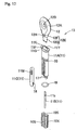
- Fig. 2 is an exploded perspective view of the sputum-collecting
tool kit;
- Fig. 3 shows explanatory diagrams that illustrate the
method of use of the sputum-collecting tool kit, with Fig. 3
(a) showing the state immediately prior to the removal of the
sputum-collecting tool following the opening of the cover body,
Fig. 3 (b) showing the state immediately prior to the
insertion of the sputum-collecting device into the mouth, Fig.
3 (c) showing a state in which the cap of the collection
sample container is removed, Fig. 3 (d) showing the state
immediately prior to the insertion of the sputum-collecting
device that has collected sputum into the collection sample
container, and Fig. 3 (e) showing the state immediately prior
to the insertion of the integrated collection sample container
into the envelope following the insertion of the sputum-collecting
device into the collection sample container;
- Fig. 4 shows the sputum-collecting device, with Fig. 4 (a)
showing a perspective view of this sputum-collecting device,
Fig. 4 (b) showing a partially sectional side view of the
upper part of the same, Fig. 4 (c) showing a plan view, and
Fig. 4 (d) showing a sectional view along line I-I in Fig. 4
(a);
- Fig. 5 shows the collection sample container, with Fig. 5
(a) showing a perspective view of the collection sample
container, Fig. 5 (b) showing a plan view of the collection
sample container in a state in which the cap has been removed,
and Fig. 5 (c) showing a sectional view along line II-II in
Fig. 5 (a);
- Fig. 6 is a perspective view which shows the state
immediately prior to the insertion of the sputum-collecting
device that has collected sputum into the collection sample
container;
- Fig. 7 is a perspective view of the collection sample
container into which the sputum-collecting device has been
inserted and integrated;
- Fig. 8 is a longitudinal sectional view of the collection
sample container into which the sputum-collecting device has
been inserted and integrated;
- Fig. 9 shows longitudinal sectional views of portions of
the removal piece of the collection sample container, with Fig.
9 (a) showing the state immediately prior to the twisting off
of the removal piece, and Fig. 9 (b) showing a state in which
the removal piece has been twisted off;
- Figs. 10 (a) through 10 (e) show front views and side
views of other sputum-collecting devices;
- Fig. 11 is a perspective view showing a state in which
the collection sample container into which the sputum-collecting
device has been inserted is held in an upright
attitude;
- Fig. 12 is an exploded perspective view showing another
sputum-collecting device;
- Fig. 13 is a side view of the sputum-collecting device
shown in Fig. 12;
- Fig. 14 is a perspective view showing another collection
sample container in a state in which the cap has been removed;
- Fig. 15 is a longitudinal sectional front view of the
collection sample container shown in Fig. 14;
- Fig. 16 is a longitudinal sectional front view showing a
state in which the sputum-collecting device shown in Fig. 12
has been inserted into the collection sample container shown
in Fig. 14; and
- Fig. 17 is a longitudinal sectional front view showing a
state in which the handle part and upper part have been
removed in the collection sample container shown in Fig. 16.
-
BEST MODE FOR CARRYING OUT THE INVENTION
-
A sputum-collecting tool kit 2 accommodating the sputum-collecting
tool 1 of the present invention is shown in Fig. 1,
and an exploded perspective view of the parts constituting
this sputum-collecting tool kit 2 is shown in Fig. 2. The
abovementioned sputum-collecting tool kit 2 comprises a
substantially rectangular box-form paper (or plastic) casing
main body 3 which accommodates the abovementioned sputum-collecting
tool 1, and a paper (or plastic) cover body 4 which
is attached to one of the two long sides of the casing main
body 3 in order to close off the open side (upper side) of
this casing main body 3, so that this cover body 4 is free to
open and close by swinging. The abovementioned casing main
body 3 is constructed so that the upper surface and one of the
four side surfaces are open, so that a substantially
rectangular tray 9 made of plastic and molded by vacuum
molding can be inserted from the side-surface opening part 3A,
and so that the upper surface of this inserted tray 9 can be
exposed via the upper-surface opening part 3B for the tray 9.
As is shown in Fig. 2, recesses 9B and 9C which can
accommodate a sputum-collecting device 13 and collection
sample container 14 that constitute the abovementioned sputum-collecting
tool 1 are disposed in the abovementioned tray 9,
and the system is devised so that the sputum-collecting device
13 and collection sample container 14 cannot move irregularly
when accommodated in these recesses 9B and 9C. However, it
would also be possible to work the present invention by
disposing anchoring fittings that respectively anchor and hold
the sputum-collecting device 13 and collection sample
container 14 in the casing main body 3 instead of the recesses
9B and 9C, and the means used to fix the positions of the
sputum-collecting device 13 and collection sample container 14
in place with respect to the casing main body 3 can be freely
altered. Depending on the case, furthermore, such means used
to fix the positions of the abovementioned sputum-collecting
device 13 and collection sample container 14 may be omitted;
for example, such parts may be combined as a bag or the like.
-
A diagram explaining use is printed on the inside surface
(undersurface) of the abovementioned cover body 4. As is
shown in Figs. 1 and 2, six explanatory diagrams 5A through 5F
can be visually recognized by placing the cover body 4 in an
open state. Accordingly, the following advantage is obtained:
namely, not only can the method of use be checked immediately
merely by placing the cover body 4 in an open state, but
sputum collection can be performed without error while viewing
the explanatory diagrams 5A through 5F during use as well.
However, it would also be possible to work the invention
without integrating the cover body 4 and casing main body 3, e.
g., by separately manufacturing the casing main body 3 and
cover body 4, printing a diagram explaining use on the
abovementioned cover body 4, constructing this cover body 4 so
the cover body 4 is self-standing, superimposing the casing
main body 3 and cover body 4, and achieving integration by
packaging using packaging paper or the like. Here, furthermore,
an embodiment is described in which as diagram explaining use
is directly printed on the inside surface of the cover body 4;
however, it would also be possible to bond a paper or plastic
sheet member or the like on which a diagram explaining used is
printed to the inside surface of the cover body 4, or to
fasten such a member in place using an anchoring mechanism or
the like. Furthermore, it would also be possible to construct
the system so that the abovementioned cover body 4 can be held
at a specified angle (e. g., an arbitrary angle in the range
of 90 degrees to less than 180 degrees) with respect to the
upper surface of the casing main body 3, or to construct the
system so that the system can be used in a state in which the
cover body is opened 180 degrees.
-
Furthermore, an accommodating part 7 which can
accommodate a mailing envelope 6 used for the postal shipping
of the abovementioned sputum-collecting tool 1 that has
collected sputum is disposed on the abovementioned cover body
4. Namely, an opening part 4A is formed in the right side of
the cover body 4 in' Figs. 1 and 2, and the system is devised
so that this enveloped 6 can be inserted and accommodate
inside the cover body 4 via this opening part 4A. A circular
arc form cut-out 4A is formed in substantially the central
portion (with respect to the outer edge direction) in the
inside portion of the right-side outer edge part of the cover
body 4, so that the following advantage is obtained: namely,
the abovementioned envelope 6 that has been accommodated can
easily be removed via the cut-out 4B. However, the cut-out 4B
may also be omitted in the working of the present invention.
The abovementioned enveloped 6 has a size that allows postal
shipping as a fixed type postal item among first class mail
constituting ordinary mail according to Japanese postal
regulations. However, some other size may also be used. The
member 8 is a sheet form (or thin film form) paper (or plastic)
member 8 which is bonded to the upper surface of the casing
main body 3 in order to achieve tight hygienic sealing of the
sputum-collecting tool 1 accommodated in the casing main body
3 shown in Figs. 1 and 2, and the system is devised so that
the member 8 can easily be peeled away by grasping and pulling
an extension part 8A on the left side.
-
As is shown in Fig. 1, Figs. 4 (a) through 4 (d) and Figs.
5 (a) through 5 (c), the abovementioned sputum-collecting tool
1 comprises a sputum-collecting device 13 made of a synthetic
resin in which a handle part 12 is disposed on one end of a
base part 11 which has a sputum-collecting part 10 with a
substantially spherical tip end surface (lower end surface)
consisting of polyurethane or cellulose acetate (that absorbs
and collects sputum) attached to the other end, and a
collection sample container 14 made of a synthetic resin that
is used for the insertion and accommodation of this sputum-collecting
device 13.
-
A low protein bonding type polyurethane whose surface has
been treated with a surfactant or macromolecular compound
shows a lower protein absorption than a general polyurethane,
and is therefore desirable from the standpoint of sputum
testing as the abovementioned polyurethane; however, a general
polyurethane may also be used. The abovementioned
polyurethane swells when sputum is absorbed. However, the
abovementioned cellulose acetate not only absorbs a larger
amount of sputum than the abovementioned polyurethane, but
also shows no swelling when sputum is absorbed; accordingly,
this cellulose acetate offers the advantages of allowing
smooth insertion of the sputum-collecting part 10 into the
collection sample container 14 following sputum absorption,
and allowing an increase in the sputum recovery rate into the
collection sample container 14, so that such cellulose acetate
is desirable. For example, Transorb manufactured by Filtrona
Richmond Co. may be cited as an example of the abovementioned
cellulose acetate resin.
-
Furthermore, the abovementioned handle part 12 has a
substantially circular shape as seen in a front view; moreover,
the diameter of this handle part 12 is set at a dimension that
is roughly twice the left-right width dimension of the base
part 11, and the grip faces 12A, 12A that are positioned on
both ends in the thickness direction are formed substantially
flat, so that the handle part 12 is easy to grip. Moreover,
the thickness of the abovementioned handle part 12 is greater
than the thickness of the base part 11; however, this handle
part 12 may also have substantially the same thickness as the
base part 11. Furthermore, substantially elliptical recesses
12B are formed in substantially the central portions of the
respective grip faces 12A, 12B, so that the fingers tend not
to slip from the handle part 12.
-
Substantially elliptical recesses 12B are formed in the
abovementioned handle part 12; however, these may also be
substantially circular recesses 12B that are formed in
substantially the central portion of the handle part 12 as
shown in Fig. 10 (a), substantially crescent shaped (circular
arc form) recesses 12B that are formed in positions separated
from the central portion of the handle part 12 as shown in Fig.
10 (b), five protrusions 12C that are long in the lateral
direction, which are formed as protrusions at specified
intervals in the longitudinal direction (vertical direction in
the figures) of the handle part 12 as shown in Fig. 10 (c),
circular recesses 12B that are formed in substantially the
central portion of the handle part 12 and three circular
protrusions 12C that are formed as protrusions at specified
intervals from these recesses 12B on substantially the same
curvature radius as shown in Fig. 10 (d), or protrusions 12C
that are formed as protrusions in a range extending over
substantially all of the central portion of the handle part 12
as shown in Fig. 10 (e). The shapes, sizes and numbers of the
protrusions or recesses (or both) that are formed in the
handle part 12 in order to prevent slipping of the fingers are
not limited to the examples shown in the figures. Furthermore,
the shape of the abovementioned handle part 12 as seen in a
front view may also be substantially elliptical or the like as
seen in Figs. 10 (b), 10 (c) and 10 (e). Furthermore, the
grip faces 12A, 12A of the handle part 12 may have gently
curved surfaces that gradually move inward approaching the
central portions as shown in Fig. 10 (b). Alternatively, as
is shown in Fig. 10 (d), these grip faces 12A, 12A may have
gently curved surfaces that gradually protrude outward toward
approaching the central portions. Cases in which the grip
faces 12A, 12A are formed as substantially flat surfaces are
also included in cases in which the grip faces are constructed
as such gently curved surfaces.
-
As is shown in Figs. 4 (a) through 4 (d), the
abovementioned base part 11 comprises a base main body 11A
with a substantially oval (or rectangular) cross-sectional
shape which has the abovementioned sputum-collecting part 10
fit over one end, and in which the abovementioned handle part
12 is integrally formed on the other end, a fiber bundle 11B
(formed by bundling numerous fibers) which is accommodated in
this base main body 11A in order to suck up sputum collected
by the sputum-collecting part 10 utilizing the capillary
phenomenon, and a cover member 11C equipped with a transparent
window 11M which is transparent so that the amount of sputum
that is absorbed can be recognized by the upward movement of
the coloring agent 11b together with the movement of the
sputum (as shown for example in Fig. 6) as a result of this
coloring agent 11b (with which an intermediate portion of the
abovementioned fiber bundle 11B is colored) being dispersed by
the absorbed sputum. However, this base part 11 may have some
other construction.
-
An annular flange part 11F which is used to engage with
the inside surface of the collection sample container 14 and
place this container in a tightly closed state when the
insertion of the of the sputum-collecting device 13 into the
abovementioned collection sample container 14 is completed is
formed on the end portion of the abovementioned base main part
11A located on the side of the handle part 12, and as is shown
in Fig. 8, the interior of the collection sample container 14
can be placed in a tightly closed state by the internal
engagement of the flange part 11F with an annular engaging
part 14H formed on the inside wall of the collection sample
container 14 merely by inserting the sputum-collecting device
13 into the collection sample container 14. Furthermore, an
annular protrusion 11G which is formed as a protrusion is
formed as a stopper part that protrudes further outward than
the flange part 11F, and stops the movement of the fingers
grasping the handle part 12 toward he base part 11 by
contacting these fingers, on the end portion of the
abovementioned flange part 11F that is located on the side of
the handle part 12. However, it would also be possible to
form a plurality of protrusions as protrusions at appropriate
intervals along the circumferential edge, or to work the
invention with these protrusions omitted.
-
As is shown in Fig. 5 (a) through 5 (c) and Fig. 9 (a),
the abovementioned collection sample container 14 contains a
specified amount of accumulated preservative liquid E, and
comprises a container main body 14A which has a substantially
oval cross-sectional shape that allows the insertion of the
abovementioned sputum-collecting device 13, and a cap 14B for
closing off the upper end opening part of this container main
body 14A. However, the present invention may also be worked
by mounting a film inside the container main body 14A so that
no accumulated preservative liquid E flows out to the outside.
Furthermore, if the abovementioned film is constructed so that
this film is ruptured when the sputum-collecting device 13 is
inserted, this film can be used in a convenient manner.
-
The lower part 14a of the abovementioned container main
body 14A is formed with a substantially oval cross-sectional
shape that allows the insertion of the base part 11 of the
abovementioned sputum-collecting device 13, and the upper part
14b is formed with a substantially circular cross-sectional
shape which is larger than that of the abovementioned lower
part 14a, and which allows the insertion of the handle part 12
of the abovementioned sputum-collecting device 13; furthermore,
respective U-shaped cut-outs 14K are formed in both surfaces
of the container main body 14A in the thickness direction.
However, these cut-outs 14K may also be omitted. As a result
of both the left and right sides of the handle part 12 of the
sputum-collecting device 13 being covered by the
abovementioned upper part 14b, other objects can be prevented
from contacting the handle part 12.
-
As is shown in Figs. 9 (a) and 9 (b), a round rod form
(prism form or other form) removal piece 15 decreasing in
diameter in the downward direction, which forms a projection
that protrudes downward and which makes it possible to remove
the abovementioned preservative liquid E (constituting an
internal storage liquid) together with the sputum by being
twisted off so that this removal piece 15 is cut away, is
disposed on the lower end of the abovementioned collection
sample container 14. This removal piece 15 may be formed as
an integral part of the collection sample container 14, or a
separate part may be attached to the collection sample
container 14 by welding or the like. Moreover, the
abovementioned removal piece 15 may also be devised so that
this removal piece can be utilized as a leg that can make the
collection sample container 14 self-standing by causing the
abovementioned removal piece 15 to punch into the
abovementioned tray 9 as shown in Fig. 3 (d). The symbol 16
in Figs. 9 (a) and 9 (b) indicates a filter, and this filter
is devised so that dust or the like that has inadvertently
been allowed to enter the collection sample container 14 does
not exit the device together with the sputum; in some cases,
however, this filter may be omitted. The present invention
may also be embodied with this filter 16 disposed in the
collection sample container 14 shown in Figs. 14 and 15.
-
Next, the method of use of the abovementioned sputum-collecting
tool kit 2 will be described. First, after the
cover body 4 is placed in closed state as shown in Fig. 3 (a),
the member 8 is peeled away, and the sputum-collecting device
13 is removed from the casing main body 3. Next, after the
handle part 12 of the sputum-collecting device 13 is grasped
in order to perform sputum collection while viewing the
explanatory diagrams of the cover body 4, the sputum-collecting
part 10 is placed in the mouth, and sputum is
adsorbed on this sputum-collecting part 10 as shown in Fig. 3
(b). During the collection of sputum by this sputum-collecting
part 10, the collection sample container 14 is removed from
the casing main body 3, and, after the cap 14B is removed from
the collection sample container 14 as shown in Fig. 3 (c), an
upright attitude (self-standing attitude) is maintained by
inserting the removal piece 15 of the lower part 14a of the
container main body 14A into a specified location of the tray
9 as shown in Fig. 3 (d). Furthermore, a recess 9A is formed
as a holding part for holding the collection sample container
14 in an upright attitude in the location of the
abovementioned tray 9 where the removal piece 15 is inserted
as shown in Figs. 1 and 2, and the system is devised so that
the abovementioned upright attitude can be maintained with
good stability by inserting and positioning the lower end
portion of the lower part 14a of the container main body 14A
in this recess 9A; however, this recess 9A may also be omitted.
It is judged by the condition of the coloring agent 11b
whether or not the amount of sputum collected in the
abovementioned sputum-collecting part 10 has exceeded the
abovementioned specified amount. In cases where the coloring
agent 11b can be seen through the window 11M as shown in Fig.
6, it is judged that the specified amount has been reached,
the sputum-collecting device 13 is inserted from above into
the collection sample container 14 set in the abovementioned
self-standing attitude, and the sputum collection work is
ended as shown in Fig. 3 (d). The collection sample container
14 into which this sputum-collecting device 13 has been
inserted is removed from the casing main body 13, the
collection sample container 14 is inserted into the envelope 6
as shown in Fig. 3 (e), and is sent by mail to a specified
inspection organ where various types of inspections are
performed, and the inspection results are then sent back.
-
In the case of a sputum-collecting tool kit 2 that is not
equipped with the abovementioned casing main body 3, the
present invention may also be worked by providing a leg part G
with a cruciform shape that can achieve a self-standing
attitude on the lower end of the collection sample container
14 (the shape is different from that shown in Fig. 5; however,
this part may also have the same shape as that shown in Fig. 5)
(a shape such as a circular disk form shape, square plate form
shape or the like may be used as long as this shape can
achieve a self-standing attitude) in a freely detachable
manner or so that this part can easily be removed.
-
Figs. 12 and 13 show a sputum-collecting device 13 with a
different construction, and Figs. 14 and 15 show a collection
sample container 14 with a different construction. Here, a
sputum-collecting tool kit 2 is constructed by accommodating
such a sputum-collecting device 13 and collection sample
container 14 in the casing main body 3 shown in Fig. 1, and
this kit is used according to the method of use described
below. Furthermore, in Figs. 12 through 16, parts that are
not particularly described in the figures are the same as
parts in Figs. 1 through 9.
-
In the sputum-collecting device 13 shown in Figs. 12 and
13, a sputum-collecting part 10X which has substantially the
shape of a rectangular solid (consisting of a material with
low protein absorption such as polyurethane or cellulose
acetate in the same manner as described above), which has
recesses 10S formed over the entire region in the longitudinal
direction (vertical direction) in an intermediate part in the
left-right lateral direction in both surfaces in the thickness
direction, and which is used to absorb and collect sputum, is
attached to one end, and a base part 11 to which a handle part
12 in which the abovementioned recesses 12B are formed in
stages so that these recesses 12B increase in size in stages
toward the grip faces 12A (two stages are shown in the figures;
however, three or more stages may also be used) is detachably
attached is disposed on the other end.
-
The abovementioned base part 11 comprises a base main
body 11A in which an opening part 11K that allows the
insertion of a skirt part 12E that is extended downward from
the lower end of the abovementioned handle part 12 is formed
on the upper end, a fiber bundle 11B (the same entity as that
shown in Fig. 6; formed by bundling numerous fibers) which is
accommodated in this base main body 11A in order to suck up
sputum collected by the sputum-collecting part 10X utilizing
the capillary phenomenon, and a cover member 11C equipped with
a transparent window 11M which is transparent so that the
amount of sputum that is absorbed can be recognized by the
upward movement of the coloring agent 11b together with the
movement of the sputum (as shown for example in Fig. 6) as a
result of this coloring agent 11b (with which an intermediate
portion of the abovementioned fiber bundle 11B is colored)
being dispersed by the absorbed sputum. A flange part 11F
which protrudes outward in the left-right direction from
another position is formed on the upper end on which the
opening part 11K of the abovementioned base main body 11A is
formed, and a protrusion 11G which is used to perform
positioning of the sputum-collecting device 13 by contacting
the annular corner wall surface 14G that is formed on the
upper end of the lower part 14a of the collection sample
container 14 when the sputum-collecting device 13 is inserted
into the collection sample container 14 as shown in Fig. 16 is
formed on the portion directly beneath the abovementioned
flange part 11F. Furthermore, pairs of left and right
anchoring claws 17, 17 and 18, 18 that protrude to the inside
of the base main body 11A are integrally formed on the inside
surface of the abovementioned cover member 11C on the side of
the sputum-collecting part 10X and the inside surface of the
abovementioned base main body 11A on the side of the sputum-collecting
part 10X, thus making it possible to maintain an
anchoring effect that prevents the sputum-collecting part 10X
from slipping off of the cover member 11C or base main body
11A by causing the anchoring claws 17, 17 and 18, 18 (only one
of the anchoring claws 18 is shown in the figures) to bite
into the abovementioned sputum-collecting part 10X in a state
in which the abovementioned sputum-collecting part 10X is
clamped between the cover member 11C and base main body 11A.
Furthermore, an annular groove 20 that can hold ring-form
packing 19 is formed in the vicinity of the central portion of
the abovementioned base main body 11A in the longitudinal
direction (vertical direction in the figures), so that the
following advantage can be obtained: namely, if packing 19 is
disposed in the base main body 11A, the leakage of the
preservative liquid E or the like in a state in which the
sputum-collecting device 13 that has collected sputum is
inserted into the collection sample container 14 as shown in
Fig. 16 can be more securely prevented than in a construction
in which tight closing is accomplished by the engagement shown
in Fig. 7. The shape, size and number of the abovementioned
anchoring claws 17 and 18 are not limited to those shown in
the figures.
-
The abovementioned skirt part 12E comprises an engaging
part 12F which has a substantially oval external shape that
allows internal engagement with the abovementioned
substantially oval opening part 11K, and a guide part 12G
having an external shape with smaller dimensions than those of
the opening part 11K at the lower end of this engaging part
12F. In a state in which the abovementioned engaging part 12F
is engaged with the opening part 11K, protrusions 11T which
act as anchoring parts that are anchored with recesses 12H
that act as anchored parts disposed in two locations in the
circumferential direction on the outer surface of the
abovementioned engaging part 12F, with these protrusions 11T
being disposed in a state in which these parts protrude inward
into the opening part 11K of the abovementioned base main body
11A, thus devising the system so that the handle part 12
cannot easily slip off of the base main body 11A. Furthermore,
in Fig. 12, the recesses 12H and protrusions 11T respectively
appear to be entities with surfaces on mutually opposite sides.
Moreover, as is shown in Fig. 16, the anchoring force between
the abovementioned anchoring parts and anchored parts is set
so that in cases where the handle part 12 is pulled out in a
state in which the sputum-collecting device 13 that has
collected sputum is inserted into the collection sample
container 14, the base part 11 remains "as is" in a state in
which this base part is inserted into the interior of the
collection sample container 14 in the state shown in the
figures, and only the handle part 12 is separated from the
base part 11.
-
The sputum-collecting device 14 shown in Figs. 14 and 15
comprises a container main body 14A which has substantially
the same shape as the container main body 14A shown in Fig. 5,
and a cap 14B consisting of an engaging part 14D that
internally engages with the upper end portion inside wall
surface 14H of the lower part 14a that constitutes the
container main body 14A connected to the lower end of a
substantially circular plate form grip part 14C. The symbol
15 indicated in the figures is the abovementioned removal
piece 15, and is integrally formed on the lower end of the
container main body 14A. Furthermore, a V-shaped peripheral
groove 14X is formed in the bottom surface of the
abovementioned upper part 14b, so that the removal piece 15
can easily be twisted off.
-
The V-shaped peripheral groove 14V used as a cut-away
portion that allows the easy twisting off of the upper part
14a is formed in substantially the boundary area between the
upper part 14a and lower part 14b of the abovementioned
container main body 14A, and is devised so that the upper part
14a can easily be cut away. Here, a peripheral groove 14V is
indicated; however, it would also be possible to form thin
parts in a plurality of locations in the circumferential
direction, as long as these parts can easily be twisted off.
-
Furthermore, a peripheral groove 14M for holding ring-form
packing 21 is formed in the lower end of the
abovementioned engaging part 14D, so that the leakage of the
preservative liquid inside the container main body 14A to the
outside is securely prevented.
-
As is shown in Fig. 16, the collection sample container
14 into which the abovementioned sputum-collecting device 13
that has collected sputum has been inserted is placed in the
envelope 6, and is sent by mail to a specified inspection
organ; however, as is shown in Fig. 17, the collection sample
container 14 in a state in which the upper part 14b has been
twisted off along with the removal of the handle part 12 ma7
be placed in the envelope 6 and sent by mail, the collection
sample container 14 in a state in which only the handle part
12 has been removed may be placed in the envelope 6 and sent
by mail, or the collection sample container 14 in a state in
which only the upper part 14b has been twisted off may be
placed in the envelope 6 and sent by mail. Fig. 17 shows the
collection sample container 14 in a state in which the handle
part 12 has been removed and the upper part 14b has been
twisted off in order to prevent collisions caused by the upper
part which has a large width in the left-right width direction
when centrifuging tubes are lined up in a tube rack after
samples have been mounted in these centrifuging tubes.
INDUSTIRAL APPLICABILTIY
-
In addition to the shipping of sputum-collecting tools
that have collected sputum to inspection organs or the like by
mail, these sputum-collecting tools can also be directly
carried. Besides using various types of synthetic resins, the
collection sample container of the sputum-collecting tool can
be manufactured using any type of material such as a metal,
wood, etc., as long as the material used does not easily
undergo deformation or allow liquid leakage.