EP1550981A2 - System and method for image noise reduction using a minimal error spatio-temporal recursive filter - Google Patents
System and method for image noise reduction using a minimal error spatio-temporal recursive filter Download PDFInfo
- Publication number
- EP1550981A2 EP1550981A2 EP04257841A EP04257841A EP1550981A2 EP 1550981 A2 EP1550981 A2 EP 1550981A2 EP 04257841 A EP04257841 A EP 04257841A EP 04257841 A EP04257841 A EP 04257841A EP 1550981 A2 EP1550981 A2 EP 1550981A2
- Authority
- EP
- European Patent Office
- Prior art keywords
- output
- spatial
- temporal
- filtration
- unit
- Prior art date
- Legal status (The legal status is an assumption and is not a legal conclusion. Google has not performed a legal analysis and makes no representation as to the accuracy of the status listed.)
- Granted
Links
- 238000000034 method Methods 0.000 title claims abstract description 28
- 230000009467 reduction Effects 0.000 title description 3
- 230000002123 temporal effect Effects 0.000 claims abstract description 98
- 238000001914 filtration Methods 0.000 claims description 80
- 238000002156 mixing Methods 0.000 claims description 16
- 230000000295 complement effect Effects 0.000 claims description 10
- 230000015572 biosynthetic process Effects 0.000 claims description 7
- 238000003786 synthesis reaction Methods 0.000 claims description 7
- 238000000354 decomposition reaction Methods 0.000 claims description 5
- 238000012545 processing Methods 0.000 claims description 5
- 230000002596 correlated effect Effects 0.000 abstract description 6
- 239000000203 mixture Substances 0.000 abstract description 6
- 238000010586 diagram Methods 0.000 description 11
- 230000003068 static effect Effects 0.000 description 10
- 238000012935 Averaging Methods 0.000 description 7
- 238000003384 imaging method Methods 0.000 description 5
- 230000003044 adaptive effect Effects 0.000 description 3
- 238000013459 approach Methods 0.000 description 2
- 238000012937 correction Methods 0.000 description 2
- 230000000694 effects Effects 0.000 description 2
- 230000002708 enhancing effect Effects 0.000 description 2
- 238000009499 grossing Methods 0.000 description 2
- 230000000873 masking effect Effects 0.000 description 2
- 238000005070 sampling Methods 0.000 description 2
- 230000003595 spectral effect Effects 0.000 description 2
- 238000003325 tomography Methods 0.000 description 2
- 230000008901 benefit Effects 0.000 description 1
- 230000003139 buffering effect Effects 0.000 description 1
- 230000008859 change Effects 0.000 description 1
- 230000007547 defect Effects 0.000 description 1
- 230000001934 delay Effects 0.000 description 1
- 238000002059 diagnostic imaging Methods 0.000 description 1
- 229910003460 diamond Inorganic materials 0.000 description 1
- 239000010432 diamond Substances 0.000 description 1
- 238000010894 electron beam technology Methods 0.000 description 1
- 239000000284 extract Substances 0.000 description 1
- 239000012530 fluid Substances 0.000 description 1
- 125000001475 halogen functional group Chemical group 0.000 description 1
- 238000002675 image-guided surgery Methods 0.000 description 1
- 230000004048 modification Effects 0.000 description 1
- 238000012986 modification Methods 0.000 description 1
- 238000004321 preservation Methods 0.000 description 1
- 230000008569 process Effects 0.000 description 1
- 238000000926 separation method Methods 0.000 description 1
- 238000002604 ultrasonography Methods 0.000 description 1
Images

Classifications
-
- G06T5/70—
-
- G—PHYSICS
- G06—COMPUTING; CALCULATING OR COUNTING
- G06T—IMAGE DATA PROCESSING OR GENERATION, IN GENERAL
- G06T5/00—Image enhancement or restoration
- G06T5/20—Image enhancement or restoration by the use of local operators
-
- G—PHYSICS
- G06—COMPUTING; CALCULATING OR COUNTING
- G06T—IMAGE DATA PROCESSING OR GENERATION, IN GENERAL
- G06T5/00—Image enhancement or restoration
- G06T5/50—Image enhancement or restoration by the use of more than one image, e.g. averaging, subtraction
-
- G—PHYSICS
- G06—COMPUTING; CALCULATING OR COUNTING
- G06T—IMAGE DATA PROCESSING OR GENERATION, IN GENERAL
- G06T2207/00—Indexing scheme for image analysis or image enhancement
- G06T2207/10—Image acquisition modality
- G06T2207/10016—Video; Image sequence
-
- G—PHYSICS
- G06—COMPUTING; CALCULATING OR COUNTING
- G06T—IMAGE DATA PROCESSING OR GENERATION, IN GENERAL
- G06T2207/00—Indexing scheme for image analysis or image enhancement
- G06T2207/10—Image acquisition modality
- G06T2207/10116—X-ray image
- G06T2207/10121—Fluoroscopy
-
- G—PHYSICS
- G06—COMPUTING; CALCULATING OR COUNTING
- G06T—IMAGE DATA PROCESSING OR GENERATION, IN GENERAL
- G06T2207/00—Indexing scheme for image analysis or image enhancement
- G06T2207/20—Special algorithmic details
- G06T2207/20172—Image enhancement details
- G06T2207/20182—Noise reduction or smoothing in the temporal domain; Spatio-temporal filtering
-
- G—PHYSICS
- G06—COMPUTING; CALCULATING OR COUNTING
- G06T—IMAGE DATA PROCESSING OR GENERATION, IN GENERAL
- G06T2207/00—Indexing scheme for image analysis or image enhancement
- G06T2207/20—Special algorithmic details
- G06T2207/20172—Image enhancement details
- G06T2207/20192—Edge enhancement; Edge preservation
Definitions
- the present invention generally relates to a system and method for reducing noise in fluoroscopic image processing.
- the present invention relates to a system and method for spatio-temporal filtration of fluoroscopic images.
- Imaging systems encompass a variety of imaging modalities, such as x-ray systems, computerized tomography (CT) systems, ultrasound systems, electron beam tomography (EBT) systems, magnetic resonance (MR) systems, and the like.
- Imaging systems generate images of an object, such as a patient, for example, through exposure to an energy source, such as x-rays passing through a patient, for example.
- the generated images may be used for many purposes. For instance, the images may be used for detecting internal defects in a structure, detecting fluid flow within a structure, or showing the presence or absence of objects in a structure.
- imaging systems may be used for minimally-invasive medical procedures and used during image-guided surgery.
- One particular type of medical imaging modality is digital fluoroscopic imaging.
- fluoroscopic image acquisition multiple x-ray images are taken successively to form an image sequence or video.
- Each individual x-ray image is called a frame.
- Each frame is made up of pixels.
- the number of x-ray photons reaching the x-ray detector is finite, which results in quantum image noise.
- Image noise is an undesired effect that may limit a visibility of anatomical features or become otherwise distracting or disturbing to a viewer.
- Modern image processing techniques in fluoroscopic systems use various filters to reduce image noise and enhance the visibility of features of interest.
- An example of a type of filter used to reduce image noise is an adaptive filter.
- adaptive filters interpret values associated with pixels. If a pixel falls within a given range of values, the pixel is considered noise, and the pixel is recomputed. If a pixel is outside of a given range, then the pixel is presumed sufficiently accurate and allowed to pass through the filter.
- Temporal filtration compares a current value of a target pixel with previous values of the same target pixel.
- a temporal filter may recalculate a noisy pixel by comparing the current value of the target pixel with previous values of the target pixel. That is, a temporal filter may replace a noisy pixel value with an average value of that pixel from several previous frames.
- Temporal noise filtration is most effective in static image sequences. During sequences of little motion, successive images contain similar information, producing an average closely resembling the true value of the pixel. However, if an object is moving, a pixel's value may widely vary over successive images. Hence, successive images may contain dissimilar information. Averaging of dissimilar information may produce a value that may not resemble the true value of the current pixel. Therefore, temporal filtration is an unsatisfactory method of enhancing a moving image because the averaging of frames may produce unwanted motion blur or motion lag.
- Spatial filtration compares a target pixel's current value with values of the target pixel's neighbors. The neighboring pixels are then used to compute a new value for the noisy pixel.
- the neighbors of a pixel are the pixels surrounding the target pixel in a current frame.
- a typical neighborhood may be a four pixel neighborhood, which consists of the target pixel, and the pixels directly north, south, east, and west.
- a four pixel neighborhood forms a diamond shape around the target pixel.
- Another typical pixel neighborhood is an eight pixel neighborhood.
- An eight pixel neighborhood consists of the target pixel, and the pixels north, south, east, west, northeast, northwest, southeast, and southwest.
- An eight pixel neighborhood forms a box around the target pixel.
- Many configurations of pixel neighborhoods currently exist.
- spatial noise filtration is equally effective for filtering static and dynamic objects in image sequences.
- the value of a target pixel may vary widely.
- an averaging of a target pixel's value with the target pixel's value in previous frames would produce motion lag.
- a target pixel's neighborhood in the current image may generally contain similar information to the true value of the target pixel.
- An average value amongst a neighborhood may produce a value closely resembling the true value of the target pixel.
- spatial artifacts may be lost edges, false edges, intra-region smoothing, segmented appearance, "patchiness,” or "blockiness.”
- the spatial artifacts present in dynamic regions of an image, are generally more tolerable than the motion lag caused by temporal filtration with equivalent noise reduction.
- spatial filtration introduces artifacts while temporal filtration does not. The artifacts consistently degrade an image, making details of the image difficult to view. Therefore, spatial filtration is an unsatisfactory method of enhancing static objects in a sequence.
- a system includes a temporal filtration unit that filters input data and produces an output.
- a spatial filtration unit filters input data and produces an output.
- a first local correlation unit correlates the input data with the temporal filter output and produces a temporal correlation output.
- a second local correlation unit correlates the input data with the spatial filter output and produces a spatial correlation output.
- a mixing unit coordinates the spatial correlation output and the temporal correlation output to produce a mixing unit output.
- a multiplexer may be used to receive the mixing unit output. The multiplexer may select the temporal filter output or the spatial filter output based on the output of the mixing unit. Alternatively, a complementary unit may be used to receive the mixing unit output and generate a complement of the mixing unit output.
- a method involves acquiring an input signal to be denoised.
- the method of de-noising involves filtering the input signal using a temporal filtration technique to produce a temporal filtration output.
- the input signal is filtered using a spatial filtration technique to produce a spatial filtration output.
- the temporal filtration output may be correlated with the input signal to produce a correlation temporal output.
- the spatial filtration output may be correlated with the input signal to produce a correlation spatial output.
- the correlation spatial output and the correlation temporal output may be mixed to produce an output signal.
- the temporal filtration output and/or the spatial filtration output may be selected based on the value of the output signal.
- the output signal may be used to denoise the input image.
- a system uses a first spatial filtration unit for filtering data using a spatial filtration technique and generating a first spatial filtration output.
- a comparison unit is used for comparing a temporal comparison signal with a spatial comparison signal.
- the comparison unit output may represent a binary number.
- a multiplexer is used for receiving the comparison unit output and selecting either a temporal update signal or a spatial update signal.
- a delay unit is used for buffering an output signal and producing a delay unit output.
- the temporal update signal and the temporal comparison signal may be multiplied by a multiplication unit.
- An addition unit may be used to alter the data.
- an addition unit may be used to create the spatial update signal and the spatial comparison signal.
- the output signal may be the input data altered by the temporal update signal, the spatial update signal, or both the temporal update signal and the spatial update signal.
- a second spatial filtration unit may be used to filter the output of the delay unit and generate a second spatial filtration output.
- the second spatial filtration output may be used to compute the temporal comparison signal.
- the delay unit output may be used to compute the temporal update signal.
- a minimal error spatio-temporal recursive filter may be used with a multiresolution spatial filter.
- the minimum error spatio-temporal recursive filter may be implemented in the synthesis portion of the multiresolution spatial filter.
- the system and method of the invention allow image noise to be minimized while avoiding motion lag in dynamic regions of the image and preserving spatial detail in static regions of the image. Hence, image resolution for both static and dynamic image regions may be increased.
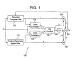
- Figure 1 illustrates a data flow diagram 100 of a minimal-difference spatio-temporal (MDST) filter used according to an embodiment of the present invention.
- the data flow diagram 100 represents various units and flow of data in computing an output signal y from an input signal x .
- the input signal x is input into four units.
- the input signal x is input into a recursive temporal filter 110, a feature preserving spatial filter 120, a local correlation unit 130, and a local correlation unit 140.
- the feature preserving spatial filter 120 and the recursive temporal filter 110 produce outputs s and t respectively.
- the outputs t and s are input into the multiplication units 170 and 180 respectively.
- the outputs t and s are also input into the local correlation units 130, 140 respectively, together with input signal x .
- Local correlation units 130, 140 produce outputs c t and c s , respectively.
- Outputs c t and c s are input into a mix function unit 150.
- the mix function unit 150 produces an output k , which is transmitted to a complementary unit 160 and a multiplication unit 170. Valid values of k may be 0 or 1, or between 0 and 1.
- the output of the complementary unit 160, (1-k) is transmitted to the multiplication unit 180.
- the output of the multiplication units 170, 180, t ' and s ', respectively, are combined at the addition unit 190 to form y , the output signal.
- the output signal y is also transmitted back to the recursive temporal filter 110 for use in computing a value of t for the next frame.
- the components of the system 100 may be separate units, may be integrated in various forms, and/or may be implemented in hardware and/or in software. Each component and signal is discussed below.
- the MDST dataflow diagram 100 performs both temporal and spatial filtration separately.
- the temporal and spatial filter outputs are mixed in proportions that are related to how closely the outputs match the latest input signal x .
- the input signal x may be an input image, a frame of data, or a stream of pixels.
- the recursive temporal filter 110 produces a weighted average of a previous frame y prev and an input signal x .
- the feature-preserving spatial filter 120 performs adjustable amounts of spatial filtration.
- the spatial filtration preserves important features of the input signal x .
- the output of the feature preserving spatial filter 120 is s.
- the first local correlation unit 130 produces a location correlation signal c t by comparing t , which is the output of the temporal filter, with the input image x .
- the value of c t may increase as t approaches matching x.
- the value of c t may decrease as t recedes from matching x .
- the comparison of t and x is performed within the pixel's neighborhood.
- the second local correlation unit 140 produces the local correlation signal c s by comparing s , which is the output of the spatial filter, with the input image x in the pixel's neighborhood.
- high values of c s may indicate a high degree of local similarity between images s and x.
- Low values of c s may indicate, by convention, a high degree of local dissimilarity between images s and x .
- the signal c t may encode the degree of local similarity between images t and x .
- the outputs, c t , c s , of the correlation units 130, 140 are then input into the mix function unit 150.
- the mix function unit 150 determines how much spatial and temporal filtration may be in the output signal y based on the correlation values c t and c s .
- the function has an adjustable bias toward spatial or temporal filtration.
- output of the mixing function k lies between 0 and 1.
- the signal k represents the portion of temporal filtration which may be used in the output y .
- k is multiplied by t to obtain t' .
- the signal t ' is a portion of t that contributes to the output image y .
- the signal k is also input into a complementary unit 160.
- k is between 0 and 1, for example, and represents the portion of the temporal filtration which may contribute to the output image y .
- the complementary unit 160 produces an output (1-k), which represents a portion of the spatial filtration that may contribute to the output image y .
- the signal (1-k) is multiplied by s to obtain s' .
- the signal s' is a portion of s that contributes to the output image y .
- the signals t ' and s ' are then added together by the addition unit 190 to create an output signal y .
- the signal y may incorporate a portion of the recursive temporal filter 110 and a portion of the feature preserving spatial filter 120.
- the output y is also sent back to the recursive temporal filter 110 for use in computing a new recursive temporal filter output value t .
- the output y is entirely composed of either the output t of the recursive temporal filter 110, or the output s of the feature-preserving spatial filter 120.
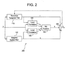
- Figure 2 illustrates a binary data flow diagram 200 of a MDST filter used in accordance with an embodiment of the present invention.
- the binary data flow diagram 200 is equivalent to data flow diagram 100, except the output k of the mixing function unit 150 is set to either 0 or 1, for example.
- the binary data flow diagram 200 is functionally equivalent to data flow diagram 100 as gamma ⁇ approaches infinity.
- the output y is therefore either entirely the output t of the recursive temporal filter 110, or entirely the output s of the feature preservation spatial filter 120.
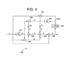
- Figure 3 illustrates a system 300 for implementing a minimal-difference spatiotemporal filter in accordance with an embodiment of the present invention.
- the system 300 utilizes a modification of the binary data flow diagram 200 to select either spatial or temporal filtration for an input image frame x .
- x is input into four units.
- the input image x is input into a spatial filter 310, an addition unit 330, an addition unit 340, and an addition unit 350.
- the output of the spatial filter 310 is s .
- the signal s is fed into an addition unit 320 and an addition unit 340.
- the signal s is used to compute update/comparison signal ds and comparison signal dt '.
- a spatial update signal ds is computed for direct use in the comparison unit 360 and as an input to the multiplexer 370.
- the spatial update/comparison signal ds is then input into the comparison unit 360 and the multiplexer 370.
- the spatial update/comparison signal is directly compared to a temporal comparison signal in the comparison unit 360.
- a temporal update signal dt is also computed, along with a temporal comparison signal dt '.
- Both temporal update signal dt and temporal comparison signal dt ' are functions of a previous frame of output, y prev .
- the parameter y prev is created by passing the output y through a delay or buffer 380, z -frame .
- the delay 380 delays the signal by one frame so that the output of the delay 380, y prev , contains a signal y of the previous frame.
- the signal y prev is input into a spatial filter 390 and an addition unit 330.
- the addition unit 330 computes the difference between the previous frame of output, y prev , and the input image frame x.
- the addition unit 330 may perform addition or subtraction.
- the difference is then multiplied by a temporal filtration coefficient, a 1 .
- the temporal filtration coefficient is generally between 0 and 1 and may be used to bias the system.
- dt the temporal update signal
- the temporal update signal dt is used to produce the output y if selected by k. Hence, dt may be added to x as correction signal d, if selected by k.
- the temporal comparison signal dt ' used for comparison differs from the temporal update signal dt used to produce the output.
- the signal dt ' is computed as a difference between a spatially-smoothed version of the previous frame and a spatially smoothed version of the current frame.
- the spatially smoothed version of the previous frame y prev is y '.
- the spatially smoothed frame y ' is the result of passing y prev through a spatial filter 390. Passing y prev through spatial filter 390 is done to reduce the noise in k .
- a 1 a 2 and the spatial filters M 1 and M 2 are identical.
- a 2 may differ from a 1 in order to control the bias of the system.
- dt ' and ds are compared in the comparison unit 360.
- the system 300 may filter dynamic regions of an image through a spatial filter and static regions of an image through a temporal filter.
- the output k is input into the multiplexer 370. If k is 1, the multiplexer 370 passes the temporal update signal dt . If k is 0, the multiplexer 370 passes the spatial update signal ds.
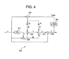
- Figure 4 illustrates a system 400 for implementing a minimal-difference spatio-temporal filter in accordance with an embodiment of the present invention.
- the system 400 is similar to the system 300, except the spatial filter 390 ( M2 ) is removed from the system 300 to create the system 400.
- the removal of the spatial filter 390 ( M2 ) from the system 300, and the subsequent change in data flow, may reduce the number of computations the system 300 performs.
- the benefit of using system 400 over the system 300 is that the system 400 is computationally less expensive.
- removing spatial filter 390 may degrade a contrast-to-noise ratio of the system 300.
- an effect of the spatial filter M2 390 is to remove noise from the signal k , which is a binary signal.
- the system 400 becomes computationally less expensive to implement, but the possibility of k dithering between 0 and 1 increases.
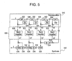
- FIG. 5 illustrates a multiresolution spatial framework system 500 that incorporates an MDST filter in accordance with an embodiment of the present invention.
- the MDST filter may then detect motion and features at various spatial scales and reduce noise at different scales.
- the system 500 incorporates MDST in a synthesis phase of multiresolution spatial filter.
- the placement also allows MDST to have different spatial or temporal biases at different spatial scales.
- Figure 5 contains a decomposition phase 510, a processing phase 520, and a synthesis phase 530.
- the decomposition phase of a multiresolution spatial filter extracts bands of frequencies from an image. In the system 500, four bands of frequencies are extracted in the decomposition phase 510. However, any number of frequency bands may be extracted.
- the Ipd blocks 502 are low-pass filters used for frequency band separation.
- the Ips blocks 504 are filters for smoothing the data from the low-pass filters 502. The Ips blocks 504 closely match the low-pass properties of the Ipi 534 low pass interpolation filters.
- the correlation between the Ips blocks 504 and the Ipi low pass interpolation filters 534 may be done to match the spectral characteristics of the subtracted signal in the decomposition phase with the spectral characterizes of the added signal in the synthesis phase.
- High-pass information may be extracted by unsharp masking, for example. Unsharp masking subtracts a smoothed version of the image from the original image. Hence, the smoothed version of the input is subtracted from the original input to create the high-pass information.
- the low-frequency image is also down sampled by down sampling units 506, and the process repeats.
- the processing phase 520 of a multiresolution spatial framework performs an operation on the extracted frequency bands.
- a band amplifier 525 is shown to operate on the image data x.
- Typical operations performed on frequency band signals are linear gain to enhance detail or non-linear gain to enhance detail and minimize noise and halo artifacts.
- the signals are up sampled by the up sampling units 532.
- the signals are also passed through Ipi 534 low pass interpolation filters.
- the signals are passed through an MDST filter 536 to produce an image with less noise than known multiresolution spatial frameworks.
- Figure 6 illustrates a method 600 for implementing a minimal-difference spatio-temporal filter in accordance with an embodiment of the present invention.
- an input image or signal is acquired.
- the input image may be a frame of data, an image, or a stream of pixels.
- the input image is passed through two separate filters.
- the input image is filtered both spatially and temporally.
- the outputs of the filters are correlated with the input signal.
- the output of the spatial filter is correlated with the input signal to determine a difference between the input signal, and the spatially filtered version of the input signal.
- the output of the temporal filter is correlated with the input signal to determine a difference between the input signal, and the temporally filtered version of the input signal.
- both correlations produce an output.
- the output of the correlations are used to coordinate the amount of temporal or spatial filtration to be applied to the output.
Abstract
Description
- The present invention generally relates to a system and method for reducing noise in fluoroscopic image processing. In particular, the present invention relates to a system and method for spatio-temporal filtration of fluoroscopic images.
- Imaging systems encompass a variety of imaging modalities, such as x-ray systems, computerized tomography (CT) systems, ultrasound systems, electron beam tomography (EBT) systems, magnetic resonance (MR) systems, and the like. Imaging systems generate images of an object, such as a patient, for example, through exposure to an energy source, such as x-rays passing through a patient, for example. The generated images may be used for many purposes. For instance, the images may be used for detecting internal defects in a structure, detecting fluid flow within a structure, or showing the presence or absence of objects in a structure. Additionally, imaging systems may be used for minimally-invasive medical procedures and used during image-guided surgery.
- One particular type of medical imaging modality is digital fluoroscopic imaging. During fluoroscopic image acquisition, multiple x-ray images are taken successively to form an image sequence or video. Each individual x-ray image is called a frame. Each frame is made up of pixels. The number of x-ray photons reaching the x-ray detector is finite, which results in quantum image noise. Image noise is an undesired effect that may limit a visibility of anatomical features or become otherwise distracting or disturbing to a viewer.
- Modern image processing techniques in fluoroscopic systems use various filters to reduce image noise and enhance the visibility of features of interest. An example of a type of filter used to reduce image noise is an adaptive filter. Generally, adaptive filters interpret values associated with pixels. If a pixel falls within a given range of values, the pixel is considered noise, and the pixel is recomputed. If a pixel is outside of a given range, then the pixel is presumed sufficiently accurate and allowed to pass through the filter.
- Traditionally, there are two techniques used to recalculate pixel value and reduce unwanted fluoroscopic image noise using adaptive filters: temporal and spatial filtration.
- Temporal filtration compares a current value of a target pixel with previous values of the same target pixel. A temporal filter may recalculate a noisy pixel by comparing the current value of the target pixel with previous values of the target pixel. That is, a temporal filter may replace a noisy pixel value with an average value of that pixel from several previous frames.
- Temporal noise filtration is most effective in static image sequences. During sequences of little motion, successive images contain similar information, producing an average closely resembling the true value of the pixel. However, if an object is moving, a pixel's value may widely vary over successive images. Hence, successive images may contain dissimilar information. Averaging of dissimilar information may produce a value that may not resemble the true value of the current pixel. Therefore, temporal filtration is an unsatisfactory method of enhancing a moving image because the averaging of frames may produce unwanted motion blur or motion lag.
- Spatial filtration compares a target pixel's current value with values of the target pixel's neighbors. The neighboring pixels are then used to compute a new value for the noisy pixel. The neighbors of a pixel are the pixels surrounding the target pixel in a current frame. A typical neighborhood may be a four pixel neighborhood, which consists of the target pixel, and the pixels directly north, south, east, and west. A four pixel neighborhood forms a diamond shape around the target pixel. Another typical pixel neighborhood is an eight pixel neighborhood. An eight pixel neighborhood consists of the target pixel, and the pixels north, south, east, west, northeast, northwest, southeast, and southwest. An eight pixel neighborhood forms a box around the target pixel. Many configurations of pixel neighborhoods currently exist.
- Unlike temporal filtration, spatial noise filtration is equally effective for filtering static and dynamic objects in image sequences. During image sequences containing motion, the value of a target pixel may vary widely. As explained above, an averaging of a target pixel's value with the target pixel's value in previous frames, would produce motion lag. Nevertheless, a target pixel's neighborhood in the current image may generally contain similar information to the true value of the target pixel. An average value amongst a neighborhood may produce a value closely resembling the true value of the target pixel.
- However, averaging among a neighborhood in a current frame may introduce unwanted spatial artifacts. Some typical unwanted spatial artifacts may be lost edges, false edges, intra-region smoothing, segmented appearance, "patchiness," or "blockiness." The spatial artifacts, present in dynamic regions of an image, are generally more tolerable than the motion lag caused by temporal filtration with equivalent noise reduction. However, for static objects in an image, spatial filtration introduces artifacts while temporal filtration does not. The artifacts consistently degrade an image, making details of the image difficult to view. Therefore, spatial filtration is an unsatisfactory method of enhancing static objects in a sequence.
- Various combinations of spatial and temporal filters currently exist. Most combinations attempt to balance the inability of a spatial filter to effectively enhance static regions in an image versus the inability of a temporal filter to effectively enhance dynamic regions in an image. Typical combinations of spatial and temporal filters pass an image through both a spatial and temporal filter. As a result, most combinations of spatial and temporal filters introduce some degree of the disadvantages of both the spatial filter and the temporal filter into the image. The consequence being insufficient resolution of both static and dynamic regions of an image.
- Therefore, a need exists for a system and method which may preserve spatial detail in static regions, while avoiding motion lag in dynamic regions. Such a system and method may minimize image noise while also minimizing unwanted artifacts and lag associated with temporal and spatial filters.
- Certain embodiments of the present invention provide a system and method for reducing image noise with the use of a minimal error spatio-temporal recursive filter. In an embodiment, a system includes a temporal filtration unit that filters input data and produces an output. A spatial filtration unit filters input data and produces an output. A first local correlation unit correlates the input data with the temporal filter output and produces a temporal correlation output. A second local correlation unit correlates the input data with the spatial filter output and produces a spatial correlation output. A mixing unit coordinates the spatial correlation output and the temporal correlation output to produce a mixing unit output. In an embodiment, a multiplexer may be used to receive the mixing unit output. The multiplexer may select the temporal filter output or the spatial filter output based on the output of the mixing unit. Alternatively, a complementary unit may be used to receive the mixing unit output and generate a complement of the mixing unit output.
- In an embodiment, a method involves acquiring an input signal to be denoised. The method of de-noising involves filtering the input signal using a temporal filtration technique to produce a temporal filtration output. Similarly, the input signal is filtered using a spatial filtration technique to produce a spatial filtration output. Next, the temporal filtration output may be correlated with the input signal to produce a correlation temporal output. Similarly, the spatial filtration output may be correlated with the input signal to produce a correlation spatial output. Next, the correlation spatial output and the correlation temporal output may be mixed to produce an output signal. The temporal filtration output and/or the spatial filtration output may be selected based on the value of the output signal. The output signal may be used to denoise the input image.
- In an embodiment of the invention, a system uses a first spatial filtration unit for filtering data using a spatial filtration technique and generating a first spatial filtration output. A comparison unit is used for comparing a temporal comparison signal with a spatial comparison signal. The comparison unit output may represent a binary number. A multiplexer is used for receiving the comparison unit output and selecting either a temporal update signal or a spatial update signal. Finally, a delay unit is used for buffering an output signal and producing a delay unit output. The temporal update signal and the temporal comparison signal may be multiplied by a multiplication unit. An addition unit may be used to alter the data. Furthermore, an addition unit may be used to create the spatial update signal and the spatial comparison signal. The output signal may be the input data altered by the temporal update signal, the spatial update signal, or both the temporal update signal and the spatial update signal. Moreover, a second spatial filtration unit may be used to filter the output of the delay unit and generate a second spatial filtration output. The second spatial filtration output may be used to compute the temporal comparison signal. The delay unit output may be used to compute the temporal update signal.
- In another embodiment, a minimal error spatio-temporal recursive filter may be used with a multiresolution spatial filter. The minimum error spatio-temporal recursive filter may be implemented in the synthesis portion of the multiresolution spatial filter.
- The system and method of the invention allow image noise to be minimized while avoiding motion lag in dynamic regions of the image and preserving spatial detail in static regions of the image. Hence, image resolution for both static and dynamic image regions may be increased.
- The invention will now be described in greater detail, by way of example, with reference to the drawings, in which:-
- Figure 1 illustrates a data flow diagram of a minimal-difference spatio-temporal (MDST) filter used in accordance with an embodiment of the present invention.
- Figure 2 illustrates a binary data flow diagram of a minimal difference spatio-temporal (MDST) filter used in accordance with an embodiment of the present invention.
- Figure 3 illustrates a minimal-difference spatio-temporal system in accordance with an embodiment of the present invention.
- Figure 4 illustrates an alternative minimal-difference spatio-temporal system in accordance with an embodiment of the present invention.
- Figure 5 illustrates a multiresolution spatial framework system which incorporates a minimal-difference spatio-temporal filter.
- Figure 6 illustrates a method for implementing a minimal-difference spatio-temporal filter in accordance with an embodiment of the present invention.
-
- The foregoing summary, as well as the following detailed description of certain embodiments of the present invention, will be better understood when read in conjunction with the appended drawings. For the purpose of illustrating the invention, certain embodiments are shown in the drawings.
- Figure 1 illustrates a data flow diagram 100 of a minimal-difference spatio-temporal (MDST) filter used according to an embodiment of the present invention. The data flow diagram 100 represents various units and flow of data in computing an output signal y from an input signal x. The input signal x is input into four units. The input signal x is input into a recursive
temporal filter 110, a feature preservingspatial filter 120, alocal correlation unit 130, and alocal correlation unit 140. The feature preservingspatial filter 120 and the recursivetemporal filter 110 produce outputs s and t respectively. The outputs t and s are input into themultiplication units local correlation units Local correlation units mix function unit 150. Themix function unit 150 produces an output k, which is transmitted to acomplementary unit 160 and amultiplication unit 170. Valid values of k may be 0 or 1, or between 0 and 1. The output of thecomplementary unit 160, (1-k), is transmitted to themultiplication unit 180. The output of themultiplication units addition unit 190 to form y, the output signal. The output signal y is also transmitted back to the recursivetemporal filter 110 for use in computing a value of t for the next frame. The components of thesystem 100 may be separate units, may be integrated in various forms, and/or may be implemented in hardware and/or in software. Each component and signal is discussed below. - The MDST dataflow diagram 100 performs both temporal and spatial filtration separately. The temporal and spatial filter outputs are mixed in proportions that are related to how closely the outputs match the latest input signal x. The input signal x may be an input image, a frame of data, or a stream of pixels.
- The recursive
temporal filter 110 produces a weighted average of a previous frame yprev and an input signal x. The output of the recursive temporal filter is t:temporal filter 110. - The feature-preserving
spatial filter 120 performs adjustable amounts of spatial filtration. The spatial filtration preserves important features of the input signal x. The output of the feature preservingspatial filter 120 is s. - The first
local correlation unit 130 produces a location correlation signal ct by comparing t, which is the output of the temporal filter, with the input image x. The value of ct may increase as t approaches matching x. The value of ct may decrease as t recedes from matching x. The comparison of t and x is performed within the pixel's neighborhood. The secondlocal correlation unit 140 produces the local correlation signal cs by comparing s, which is the output of the spatial filter, with the input image x in the pixel's neighborhood. By convention, high values of cs may indicate a high degree of local similarity between images s and x. Low values of cs may indicate, by convention, a high degree of local dissimilarity between images s and x. Similarly, the signal c t , may encode the degree of local similarity between images t and x. - The outputs, ct , cs , of the
correlation units mix function unit 150. Themix function unit 150 determines how much spatial and temporal filtration may be in the output signal y based on the correlation values ct and cs . The function has an adjustable bias toward spatial or temporal filtration. A mix function k used with an embodiment of the present invention is as follows: - In an embodiment, output of the mixing function k lies between 0 and 1. The signal k represents the portion of temporal filtration which may be used in the output y. Hence, k is multiplied by t to obtain t'. The signal t' is a portion of t that contributes to the output image y.
- The signal k is also input into a
complementary unit 160. As k is input into thecomplementary unit 160, k is between 0 and 1, for example, and represents the portion of the temporal filtration which may contribute to the output image y. Thecomplementary unit 160 produces an output (1-k), which represents a portion of the spatial filtration that may contribute to the output image y. The signal (1-k) is multiplied by s to obtain s'. The signal s' is a portion of s that contributes to the output image y. - The signals t' and s' are then added together by the
addition unit 190 to create an output signal y. The signal y may incorporate a portion of the recursivetemporal filter 110 and a portion of the feature preservingspatial filter 120. The output y is also sent back to the recursivetemporal filter 110 for use in computing a new recursive temporal filter output value t. - Alternatively, the output y is entirely composed of either the output t of the recursive
temporal filter 110, or the output s of the feature-preservingspatial filter 120. Figure 2 illustrates a binary data flow diagram 200 of a MDST filter used in accordance with an embodiment of the present invention. The binary data flow diagram 200 is equivalent to data flow diagram 100, except the output k of themixing function unit 150 is set to either 0 or 1, for example. Moreover, the binary data flow diagram 200 is functionally equivalent to data flow diagram 100 as gamma γ approaches infinity. The output y is therefore either entirely the output t of the recursivetemporal filter 110, or entirely the output s of the feature preservationspatial filter 120. Amultiplexer 255 selects the temporal output t when k=1 and the spatial output s when k=0. Hence:
- Other elements of Figure 2 are equivalent to Figure 1.
- Figure 3 illustrates a
system 300 for implementing a minimal-difference spatiotemporal filter in accordance with an embodiment of the present invention. Thesystem 300 utilizes a modification of the binary data flow diagram 200 to select either spatial or temporal filtration for an input image frame x. In thesystem 300, x is input into four units. The input image x is input into aspatial filter 310, anaddition unit 330, anaddition unit 340, and anaddition unit 350. The output of thespatial filter 310 is s. The signal s is fed into anaddition unit 320 and anaddition unit 340. The signal s is used to compute update/comparison signal ds and comparison signal dt'. - A spatial update signal ds is computed for direct use in the
comparison unit 360 and as an input to themultiplexer 370. The spatial update/comparison signal ds is computed ascomparison unit 360 and themultiplexer 370. The spatial update/comparison signal is directly compared to a temporal comparison signal in thecomparison unit 360. The spatial update/comparison signal may also be selected to update input signal x, to create an output y, upon condition k=0. - A temporal update signal dt is also computed, along with a temporal comparison signal dt'. Both temporal update signal dt and temporal comparison signal dt' are functions of a previous frame of output, yprev . The parameter yprev is created by passing the output y through a delay or
buffer 380, z-frame . Thedelay 380 delays the signal by one frame so that the output of thedelay 380, yprev , contains a signal y of the previous frame. The signal yprev is input into aspatial filter 390 and anaddition unit 330. - The
addition unit 330 computes the difference between the previous frame of output, yprev, and the input image frame x. Theaddition unit 330 may perform addition or subtraction. The difference is then multiplied by a temporal filtration coefficient, a1 . The temporal filtration coefficient is generally between 0 and 1 and may be used to bias the system. Hence, dt, the temporal update signal, is computed as: - The temporal update signal dt is used to produce the output y if selected by k. Hence, dt may be added to x as correction signal d, if selected by k.
- However, the temporal comparison signal dt' used for comparison differs from the temporal update signal dt used to produce the output. The signal dt' is computed as a difference between a spatially-smoothed version of the previous frame and a spatially smoothed version of the current frame. The spatially smoothed version of the previous frame yprev , is y'. The spatially smoothed frame y' is the result of passing yprev through a
spatial filter 390. Passing yprev throughspatial filter 390 is done to reduce the noise in k. The difference between the spatially smoothed previous frame, y', and the spatially smoothed current frame, s, is then multiplied by a temporal filtration coefficient a2 . The temporal filtration coefficient a2 is generally between 0 and 1 and may be used in the system to introduce bias. Hence, dt' is computed as: - In an embodiment, a 1 = a 2 and the spatial filters M1 and M2 are identical.
- Alternatively, a2 may differ from a1 in order to control the bias of the system.
- As mentioned above, dt' and ds are compared in the
comparison unit 360. In an embodiment, the output k of thecomparison unit 360 depends on which magnitude, ds or dt', is smaller. If dt' < ds, then k equals 1. If dt' ≥ ds, then k=0.
- Thus, the
system 300 may filter dynamic regions of an image through a spatial filter and static regions of an image through a temporal filter. The selection signal k may be thought of as a motion signal. If k=1, object motion is unlikely and temporal averaging is safe. If k=0, the likelihood of motion is high and spatial averaging is selected. - The output k is input into the
multiplexer 370. If k is 1, themultiplexer 370 passes the temporal update signal dt. If k is 0, themultiplexer 370 passes the spatial update signal ds. The output signal y consists of the input signal x plus a correction signal d, when d equals either ds or dt:
- Alternatively, Figure 4 illustrates a
system 400 for implementing a minimal-difference spatio-temporal filter in accordance with an embodiment of the present invention. Thesystem 400 is similar to thesystem 300, except the spatial filter 390 (M2) is removed from thesystem 300 to create thesystem 400. The removal of the spatial filter 390 (M2) from thesystem 300, and the subsequent change in data flow, may reduce the number of computations thesystem 300 performs. Hence, the benefit of usingsystem 400 over thesystem 300 is that thesystem 400 is computationally less expensive. - However, removing spatial filter 390 (M2) may degrade a contrast-to-noise ratio of the
system 300. In thesystem 300, an effect of thespatial filter M2 390 is to remove noise from the signal k, which is a binary signal. By removing M2, thesystem 400 becomes computationally less expensive to implement, but the possibility of k dithering between 0 and 1 increases. - In another embodiment, the noise reduction capabilities of the MDST filter are improved when the MDST filter is incorporated into a multiresolution spatial framework. Figure 5 illustrates a multiresolution spatial framework system 500 that incorporates an MDST filter in accordance with an embodiment of the present invention. In the system 500, the MDST filter may then detect motion and features at various spatial scales and reduce noise at different scales. The system 500 incorporates MDST in a synthesis phase of multiresolution spatial filter. The placement also allows MDST to have different spatial or temporal biases at different spatial scales. The article "The Laplacian Pyramid as a Compact Image Code," in the IEEE Transactions, C-31:532-540, 1983, by Burt, P.J. and Adelson E.H., discloses a typical multiresolution spatial framework and is hereby incorporated by reference.
- Figure 5 contains a
decomposition phase 510, aprocessing phase 520, and asynthesis phase 530. The decomposition phase of a multiresolution spatial filter extracts bands of frequencies from an image. In the system 500, four bands of frequencies are extracted in thedecomposition phase 510. However, any number of frequency bands may be extracted. The Ipd blocks 502 are low-pass filters used for frequency band separation. The Ips blocks 504 are filters for smoothing the data from the low-pass filters 502. The Ips blocks 504 closely match the low-pass properties of theIpi 534 low pass interpolation filters. The correlation between the Ips blocks 504 and the Ipi low pass interpolation filters 534 may be done to match the spectral characteristics of the subtracted signal in the decomposition phase with the spectral characterizes of the added signal in the synthesis phase. High-pass information may be extracted by unsharp masking, for example. Unsharp masking subtracts a smoothed version of the image from the original image. Hence, the smoothed version of the input is subtracted from the original input to create the high-pass information. The low-frequency image is also down sampled by down samplingunits 506, and the process repeats. - The
processing phase 520 of a multiresolution spatial framework performs an operation on the extracted frequency bands. In the system 500, as an example, aband amplifier 525 is shown to operate on the image data x. Typical operations performed on frequency band signals are linear gain to enhance detail or non-linear gain to enhance detail and minimize noise and halo artifacts. - In the
synthesis phase 530, the signals are up sampled by the upsampling units 532. The signals are also passed throughIpi 534 low pass interpolation filters. Also, in thesynthesis phase 530, the signals are passed through anMDST filter 536 to produce an image with less noise than known multiresolution spatial frameworks. - Figure 6 illustrates a
method 600 for implementing a minimal-difference spatio-temporal filter in accordance with an embodiment of the present invention. Atstep 610, an input image or signal is acquired. As mentioned above, the input image may be a frame of data, an image, or a stream of pixels. Atstep 620, the input image is passed through two separate filters. The input image is filtered both spatially and temporally. Atstep 630, the outputs of the filters are correlated with the input signal. The output of the spatial filter is correlated with the input signal to determine a difference between the input signal, and the spatially filtered version of the input signal. The output of the temporal filter is correlated with the input signal to determine a difference between the input signal, and the temporally filtered version of the input signal. In an embodiment, both correlations produce an output. Atstep 640, the output of the correlations are used to coordinate the amount of temporal or spatial filtration to be applied to the output.
Claims (10)
- A system (100) for filtering image data, said system comprising:a temporal filtration unit (110) for filtering image data using a temporal technique to produce a temporal filtration output;a spatial filtration unit (120) for filtering said image data using a spatial filtration technique to produce a spatial filtration output;a first local correlation unit (130) for correlating said image data with said temporal filtration output to produce a temporal correlation output;a second local correlation unit (140) for correlating said image data with said spatial filtration output to produce a spatial correlation output; anda mixing unit (150) for coordinating said spatial correlation output and said temporal correlation output to produce a mixing unit output.
- The system of claim 1, further comprising a multiplexer (255) for receiving said mixing unit output.
- The system of claim 1, further comprising a complementary unit (160) for generating a complement of said mixing unit output.
- The system of claim 1, further comprising:(i) a multiplication unit (170) for multiplying said temporal filtration output with said mixing unit output;(ii) a multiplication unit (180) for multiplying said spatial filtration output
with said complement of said mixing unit output; and(iii) an addition unit (190) for adding a portion of said temporal filtration output and a portion of said spatial filtration output. - The system of claim 2, wherein said multiplexer (255) selects said temporal filtration output or said spatial filtration output based on said mixing unit output to alter an image.
- A system (400) for filtering image data, said system comprising:a first spatial filtration unit (310) for filtering image data using a spatial filtration technique to generate a first spatial filtration output;a comparison unit (360) for comparing a temporal comparison signal with a spatial comparison signal;a multiplexer (370) for receiving said comparison unit output and selecting a temporal update signal or a spatial update signal; anda delay unit (380) for delaying an output signal and producing a delay unit output.
- The system (400) of claim 6, wherein said comparison unit output represents a binary number.
- The system (300) of claim 6, further comprising a second spatial filtration unit (390) for filtering said delay unit (380) output using a spatial filtration technique to generate a second spatial filtration output.
- The system (300) of claim 8, wherein said second spatial filtration output is used to compute said temporal comparison signal.
- A method for filtering a signal using a multiresolution spatial filter (500), the synthesis stage (530) of said multiresolution spatial filter (500) comprising:acquiring an input signal from a decomposition (510) and processing (520) stage of a multiresolution spatial filter (500);filtering said input signal using a temporal filtration technique (536) to produce a temporal filtration output;filtering said input signal using a spatial filtration technique (536) to produce a spatial filtration output;correlating said temporal filtration output with said input signal to produce a correlation temporal output corresponding to a difference between said input signal and said temporal filtration output (536);correlating said spatial output with said input signal to produce a correlation spatial output corresponding to a difference between said input signal and said spatial output (536); andmixing said correlation spatial output and said correlation temporal output to produce an output signal (536).
Applications Claiming Priority (2)
| Application Number | Priority Date | Filing Date | Title |
|---|---|---|---|
| US744812 | 2003-12-22 | ||
| US10/744,812 US7317841B2 (en) | 2003-12-22 | 2003-12-22 | System and method for image noise reduction using a minimal error spatiotemporal recursive filter |
Publications (3)
| Publication Number | Publication Date |
|---|---|
| EP1550981A2 true EP1550981A2 (en) | 2005-07-06 |
| EP1550981A3 EP1550981A3 (en) | 2005-08-31 |
| EP1550981B1 EP1550981B1 (en) | 2010-08-11 |
Family
ID=34574733
Family Applications (1)
| Application Number | Title | Priority Date | Filing Date |
|---|---|---|---|
| EP04257841A Active EP1550981B1 (en) | 2003-12-22 | 2004-12-16 | System and method for image noise reduction using a minimal error spatio-temporal recursive filter |
Country Status (5)
| Country | Link |
|---|---|
| US (1) | US7317841B2 (en) |
| EP (1) | EP1550981B1 (en) |
| JP (1) | JP4598507B2 (en) |
| CN (1) | CN100496401C (en) |
| DE (1) | DE602004028562D1 (en) |
Cited By (4)
| Publication number | Priority date | Publication date | Assignee | Title |
|---|---|---|---|---|
| EP2180688A1 (en) * | 2008-10-21 | 2010-04-28 | Sony Corporation | Image processing apparatus, image processing method, and program |
| WO2016166199A1 (en) | 2015-04-14 | 2016-10-20 | Koninklijke Philips N.V. | Device and method for improving medical image quality |
| CN109283785A (en) * | 2018-12-05 | 2019-01-29 | 余姚德诚科技咨询有限公司 | Safety-type portable imager |
| WO2020001922A1 (en) * | 2018-06-29 | 2020-01-02 | Electricite De France | Processing of impulse noise in a video sequence |
Families Citing this family (27)
| Publication number | Priority date | Publication date | Assignee | Title |
|---|---|---|---|---|
| US7474797B2 (en) * | 2005-12-01 | 2009-01-06 | Kwe International, Inc. | Spacial-temporal processing of digital images |
| JP4915836B2 (en) * | 2005-12-15 | 2012-04-11 | 株式会社日立メディコ | Method, program, and apparatus for operating image processing apparatus |
| JP4943721B2 (en) * | 2006-03-20 | 2012-05-30 | 株式会社リコー | Color noise removal method for image data and imaging apparatus using the method |
| US8369417B2 (en) * | 2006-05-19 | 2013-02-05 | The Hong Kong University Of Science And Technology | Optimal denoising for video coding |
| US8831111B2 (en) * | 2006-05-19 | 2014-09-09 | The Hong Kong University Of Science And Technology | Decoding with embedded denoising |
| GB2438660B (en) * | 2006-06-02 | 2011-03-30 | Tandberg Television Asa | Recursive filter system for a video signal |
| US8442344B2 (en) * | 2006-08-07 | 2013-05-14 | Qualcomm Incorporated | Adaptive spatial image filter for filtering image information |
| US7952646B2 (en) * | 2006-12-27 | 2011-05-31 | Intel Corporation | Method and apparatus for content adaptive spatial-temporal motion adaptive noise reduction |
| ES2525701T3 (en) | 2007-03-26 | 2014-12-29 | Pelco. Inc. | Method of improving the images of a camcorder |
| US7978906B2 (en) * | 2007-06-14 | 2011-07-12 | Microsoft Corporation | Capturing long-range correlations in patch models |
| US11677938B2 (en) * | 2008-04-30 | 2023-06-13 | Arris Enterprises Llc | Method to reduce contour artifacts on recursive temporal filters |
| US8081224B2 (en) * | 2008-05-07 | 2011-12-20 | Aptina Imaging Corporation | Method and apparatus for image stabilization using multiple image captures |
| CN101744628B (en) * | 2008-11-28 | 2012-05-23 | 东软飞利浦医疗设备系统有限责任公司 | Denoising device and method based on motion signal feedback |
| JP5393245B2 (en) * | 2009-05-12 | 2014-01-22 | キヤノン株式会社 | Image processing apparatus, image processing apparatus control method, X-ray image capturing apparatus, and X-ray image capturing apparatus control method |
| JP5543194B2 (en) * | 2009-12-24 | 2014-07-09 | キヤノン株式会社 | Information processing apparatus, processing method, and program |
| GB2477956B (en) * | 2010-02-19 | 2014-11-05 | Snell Ltd | Objective picture quality measurement |
| JP5490236B2 (en) * | 2010-06-08 | 2014-05-14 | シャープ株式会社 | Image processing apparatus and method, image display apparatus and method |
| US8526700B2 (en) | 2010-10-06 | 2013-09-03 | Robert E. Isaacs | Imaging system and method for surgical and interventional medical procedures |
| US11231787B2 (en) | 2010-10-06 | 2022-01-25 | Nuvasive, Inc. | Imaging system and method for use in surgical and interventional medical procedures |
| US9785246B2 (en) | 2010-10-06 | 2017-10-10 | Nuvasive, Inc. | Imaging system and method for use in surgical and interventional medical procedures |
| BR112013009965A8 (en) * | 2010-10-27 | 2016-09-13 | Koninklijke Philips Electronics Nv | "SYSTEM AND METHOD" |
| US20120328161A1 (en) * | 2011-06-22 | 2012-12-27 | Palenychka Roman | Method and multi-scale attention system for spatiotemporal change determination and object detection |
| GB2513112B (en) * | 2013-04-08 | 2020-01-08 | Snell Advanced Media Ltd | Video sequence processing |
| CN112862775A (en) | 2014-07-25 | 2021-05-28 | 柯惠Lp公司 | Augmenting surgical reality environment |
| US11132769B2 (en) * | 2016-03-23 | 2021-09-28 | Koninklijke Philips N.V. | Image quality by two pass temporal noise reduction |
| US10109050B2 (en) * | 2016-06-01 | 2018-10-23 | Siemens Healthcare Gmbh | Spatiotemporal background phase correction for phase contrast velocity encoded MRI |
| DE102019122667A1 (en) * | 2019-08-22 | 2021-02-25 | Schölly Fiberoptic GmbH | Method for suppressing image noise in a video image stream, as well as the associated medical image recording system and computer program product |
Citations (5)
| Publication number | Priority date | Publication date | Assignee | Title |
|---|---|---|---|---|
| US5909516A (en) * | 1996-03-29 | 1999-06-01 | Sarnoff Corporation | Method and apparatus for decomposing an image stream into units of local contrast |
| US6259489B1 (en) * | 1996-04-12 | 2001-07-10 | Snell & Wilcox Limited | Video noise reducer |
| US6335990B1 (en) * | 1997-07-03 | 2002-01-01 | Cisco Technology, Inc. | System and method for spatial temporal-filtering for improving compressed digital video |
| US20020028025A1 (en) * | 2000-07-18 | 2002-03-07 | Hong Sung Hoon | Spatio-temporal joint filter for noise reduction |
| US20030123750A1 (en) * | 2001-12-29 | 2003-07-03 | Samsung Electronicsco., Ltd. | Apparatus for attenuating image-noise adaptively and method thereof |
Family Cites Families (23)
| Publication number | Priority date | Publication date | Assignee | Title |
|---|---|---|---|---|
| US4674125A (en) | 1983-06-27 | 1987-06-16 | Rca Corporation | Real-time hierarchal pyramid signal processing apparatus |
| GB8317407D0 (en) | 1983-06-27 | 1983-07-27 | Rca Corp | Image transform techniques |
| US4694413A (en) | 1984-07-19 | 1987-09-15 | Rca Corporation | Compact-structure input-weighted multitap digital filters |
| GB8429879D0 (en) | 1984-11-27 | 1985-01-03 | Rca Corp | Signal processing apparatus |
| US4603350A (en) | 1984-12-21 | 1986-07-29 | Rca Corporation | Interlaced digital video input filter/decimator and/or expander/interpolator filter |
| GB8518803D0 (en) | 1985-07-25 | 1985-08-29 | Rca Corp | Locating target patterns within images |
| US4698843A (en) | 1985-08-19 | 1987-10-06 | Rca Corporation | Method for compensating for void-defects in images |
| US4709394A (en) | 1985-08-23 | 1987-11-24 | Rca Corporation | Multiplexed real-time pyramid signal processing system |
| US4703514A (en) | 1985-09-16 | 1987-10-27 | Rca Corporation | Programmed implementation of real-time multiresolution signal processing apparatus |
| US4672444A (en) | 1985-11-14 | 1987-06-09 | Rca Corporation | Method for transmitting a high-resolution image over a narrow-band communication channel |
| US4663660A (en) | 1986-06-20 | 1987-05-05 | Rca Corporation | Compressed quantized image-data transmission technique suitable for use in teleconferencing |
| US4797942A (en) | 1987-03-02 | 1989-01-10 | General Electric | Pyramid processor for building large-area, high-resolution image by parts |
| US4817182A (en) | 1987-05-04 | 1989-03-28 | General Electric Company | Truncated subband coding of images |
| US4982283A (en) | 1988-05-06 | 1991-01-01 | General Electric Company | Line-sequential pyramid processing of a plurality of raster-scanned image variables |
| US5315670A (en) | 1991-11-12 | 1994-05-24 | General Electric Company | Digital data compression system including zerotree coefficient coding |
| US5321776A (en) | 1992-02-26 | 1994-06-14 | General Electric Company | Data compression system including successive approximation quantizer |
| US5276513A (en) | 1992-06-10 | 1994-01-04 | Rca Thomson Licensing Corporation | Implementation architecture for performing hierarchical motion analysis of video images in real time |
| DE69615994T2 (en) * | 1995-06-23 | 2002-06-06 | Koninkl Philips Electronics Nv | IMAGE PROCESSING METHOD FOR NOISE REDUCTION |
| JP4363667B2 (en) | 1997-06-06 | 2009-11-11 | コーニンクレッカ フィリップス エレクトロニクス エヌ ヴィ | Image noise compression method |
| SE9704184D0 (en) * | 1997-11-14 | 1997-11-14 | Astra Ab | Inhalation device |
| US6310982B1 (en) * | 1998-11-12 | 2001-10-30 | Oec Medical Systems, Inc. | Method and apparatus for reducing motion artifacts and noise in video image processing |
| US6910060B2 (en) * | 2001-05-21 | 2005-06-21 | Computational Sensor Corp. | Spatio-temporal filter and method |
| US20050107982A1 (en) * | 2003-11-17 | 2005-05-19 | Zhaohui Sun | Method and system for noise estimation from video sequence |
-
2003
- 2003-12-22 US US10/744,812 patent/US7317841B2/en active Active
-
2004
- 2004-12-16 EP EP04257841A patent/EP1550981B1/en active Active
- 2004-12-16 DE DE602004028562T patent/DE602004028562D1/en active Active
- 2004-12-21 JP JP2004369091A patent/JP4598507B2/en not_active Expired - Fee Related
- 2004-12-22 CN CNB2004101037508A patent/CN100496401C/en not_active Expired - Fee Related
Patent Citations (5)
| Publication number | Priority date | Publication date | Assignee | Title |
|---|---|---|---|---|
| US5909516A (en) * | 1996-03-29 | 1999-06-01 | Sarnoff Corporation | Method and apparatus for decomposing an image stream into units of local contrast |
| US6259489B1 (en) * | 1996-04-12 | 2001-07-10 | Snell & Wilcox Limited | Video noise reducer |
| US6335990B1 (en) * | 1997-07-03 | 2002-01-01 | Cisco Technology, Inc. | System and method for spatial temporal-filtering for improving compressed digital video |
| US20020028025A1 (en) * | 2000-07-18 | 2002-03-07 | Hong Sung Hoon | Spatio-temporal joint filter for noise reduction |
| US20030123750A1 (en) * | 2001-12-29 | 2003-07-03 | Samsung Electronicsco., Ltd. | Apparatus for attenuating image-noise adaptively and method thereof |
Cited By (8)
| Publication number | Priority date | Publication date | Assignee | Title |
|---|---|---|---|---|
| EP2180688A1 (en) * | 2008-10-21 | 2010-04-28 | Sony Corporation | Image processing apparatus, image processing method, and program |
| WO2016166199A1 (en) | 2015-04-14 | 2016-10-20 | Koninklijke Philips N.V. | Device and method for improving medical image quality |
| US10546367B2 (en) | 2015-04-14 | 2020-01-28 | Koninklijke Philips N.V. | Device and method for improving medical image quality |
| WO2020001922A1 (en) * | 2018-06-29 | 2020-01-02 | Electricite De France | Processing of impulse noise in a video sequence |
| FR3083415A1 (en) * | 2018-06-29 | 2020-01-03 | Electricite De France | PROCESSING AN IMPULSE NOISE IN A VIDEO SEQUENCE |
| US11201989B2 (en) | 2018-06-29 | 2021-12-14 | Electricite De France | Processing of impulse noise in a video sequence |
| CN109283785A (en) * | 2018-12-05 | 2019-01-29 | 余姚德诚科技咨询有限公司 | Safety-type portable imager |
| CN109283785B (en) * | 2018-12-05 | 2022-04-08 | 广东南方瑞美医疗科技有限公司 | Safety portable imager |
Also Published As
| Publication number | Publication date |
|---|---|
| US20050135698A1 (en) | 2005-06-23 |
| JP2005199061A (en) | 2005-07-28 |
| EP1550981B1 (en) | 2010-08-11 |
| JP4598507B2 (en) | 2010-12-15 |
| CN100496401C (en) | 2009-06-10 |
| CN1672636A (en) | 2005-09-28 |
| EP1550981A3 (en) | 2005-08-31 |
| DE602004028562D1 (en) | 2010-09-23 |
| US7317841B2 (en) | 2008-01-08 |
Similar Documents
| Publication | Publication Date | Title |
|---|---|---|
| EP1550981B1 (en) | System and method for image noise reduction using a minimal error spatio-temporal recursive filter | |
| JP4363667B2 (en) | Image noise compression method | |
| US5708693A (en) | Image processing for noise reduction | |
| KR0176601B1 (en) | Picture quality improving method & circuit using low-filtering and histogram equalization | |
| US6760401B2 (en) | Apparatus and method for processing of digital images | |
| EP1341124B1 (en) | Method for sharpening a digital image with signal to noise estimation | |
| JP3700804B2 (en) | Image processing method and apparatus | |
| JPH1075395A (en) | Image processing method and device | |
| US7889904B2 (en) | Image processing device, image processing method, program, storage medium and image processing system | |
| EP3072104A1 (en) | Image de-noising method | |
| JP2002541696A (en) | Image processing method, system and apparatus for noise reduction of image sequence representing linear moving object | |
| JPH1063839A (en) | Image processing method and device therefor | |
| US10068319B2 (en) | Method for noise reduction in an image sequence | |
| JPH10105701A (en) | Method and device for radio graph emphasis processing | |
| Hensel et al. | Robust and fast estimation of signal-dependent noise in medical x-ray image sequences | |
| JPH0944651A (en) | Image processing method and device therefor | |
| JP3870173B2 (en) | Image processing method, image processing apparatus, program, and computer recording medium | |
| JPH0991423A (en) | Image processing method and processor | |
| Hensel et al. | Noise reduction with edge preservation by multiscale analysis of medical x-ray image sequences | |
| Gooßen et al. | Medical X-ray image enhancement by intra-image and inter-image similarity | |
| JP2002344773A (en) | Device for reducing noise in video signal | |
| WO2009065441A1 (en) | Method and arrangement in fluoroscopy and ultrasound systems | |
| WO2021069557A1 (en) | Method and apparatus for noise reduction | |
| Tom et al. | Novel Method for Contrast Enhancement of Digital Images using Image Fusion | |
| Unaldi et al. | Local statistics based filtering method for enhancement in super-resolution image reconstruction |
Legal Events
| Date | Code | Title | Description |
|---|---|---|---|
| PUAI | Public reference made under article 153(3) epc to a published international application that has entered the european phase |
Free format text: ORIGINAL CODE: 0009012 |
|
| AK | Designated contracting states |
Kind code of ref document: A2 Designated state(s): AT BE BG CH CY CZ DE DK EE ES FI FR GB GR HU IE IS IT LI LT LU MC NL PL PT RO SE SI SK TR |
|
| AX | Request for extension of the european patent |
Extension state: AL BA HR LV MK YU |
|
| PUAL | Search report despatched |
Free format text: ORIGINAL CODE: 0009013 |
|
| AK | Designated contracting states |
Kind code of ref document: A3 Designated state(s): AT BE BG CH CY CZ DE DK EE ES FI FR GB GR HU IE IS IT LI LT LU MC NL PL PT RO SE SI SK TR |
|
| AX | Request for extension of the european patent |
Extension state: AL BA HR LV MK YU |
|
| 17P | Request for examination filed |
Effective date: 20060228 |
|
| AKX | Designation fees paid |
Designated state(s): DE FR GB |
|
| 17Q | First examination report despatched |
Effective date: 20070803 |
|
| GRAP | Despatch of communication of intention to grant a patent |
Free format text: ORIGINAL CODE: EPIDOSNIGR1 |
|
| GRAS | Grant fee paid |
Free format text: ORIGINAL CODE: EPIDOSNIGR3 |
|
| GRAA | (expected) grant |
Free format text: ORIGINAL CODE: 0009210 |
|
| AK | Designated contracting states |
Kind code of ref document: B1 Designated state(s): DE FR GB |
|
| REG | Reference to a national code |
Ref country code: GB Ref legal event code: FG4D |
|
| REF | Corresponds to: |
Ref document number: 602004028562 Country of ref document: DE Date of ref document: 20100923 Kind code of ref document: P |
|
| PLBE | No opposition filed within time limit |
Free format text: ORIGINAL CODE: 0009261 |
|
| STAA | Information on the status of an ep patent application or granted ep patent |
Free format text: STATUS: NO OPPOSITION FILED WITHIN TIME LIMIT |
|
| 26N | No opposition filed |
Effective date: 20110512 |
|
| GBPC | Gb: european patent ceased through non-payment of renewal fee |
Effective date: 20101216 |
|
| REG | Reference to a national code |
Ref country code: DE Ref legal event code: R097 Ref document number: 602004028562 Country of ref document: DE Effective date: 20110512 |
|
| PG25 | Lapsed in a contracting state [announced via postgrant information from national office to epo] |
Ref country code: GB Free format text: LAPSE BECAUSE OF NON-PAYMENT OF DUE FEES Effective date: 20101216 |
|
| PGFP | Annual fee paid to national office [announced via postgrant information from national office to epo] |
Ref country code: FR Payment date: 20131217 Year of fee payment: 10 |
|
| REG | Reference to a national code |
Ref country code: FR Ref legal event code: ST Effective date: 20150831 |
|
| PG25 | Lapsed in a contracting state [announced via postgrant information from national office to epo] |
Ref country code: FR Free format text: LAPSE BECAUSE OF NON-PAYMENT OF DUE FEES Effective date: 20141231 |
|
| P01 | Opt-out of the competence of the unified patent court (upc) registered |
Effective date: 20230528 |
|
| PGFP | Annual fee paid to national office [announced via postgrant information from national office to epo] |
Ref country code: DE Payment date: 20231121 Year of fee payment: 20 |