EP1550498B1 - Reagent cartridge with reagent containers for reagents containing particles for their non-invasive homogenization - Google Patents
Reagent cartridge with reagent containers for reagents containing particles for their non-invasive homogenization Download PDFInfo
- Publication number
- EP1550498B1 EP1550498B1 EP04029815A EP04029815A EP1550498B1 EP 1550498 B1 EP1550498 B1 EP 1550498B1 EP 04029815 A EP04029815 A EP 04029815A EP 04029815 A EP04029815 A EP 04029815A EP 1550498 B1 EP1550498 B1 EP 1550498B1
- Authority
- EP
- European Patent Office
- Prior art keywords
- container
- reagent
- cartridge
- particle
- containers
- Prior art date
- Legal status (The legal status is an assumption and is not a legal conclusion. Google has not performed a legal analysis and makes no representation as to the accuracy of the status listed.)
- Not-in-force
Links
Images


Classifications
-
- B—PERFORMING OPERATIONS; TRANSPORTING
- B01—PHYSICAL OR CHEMICAL PROCESSES OR APPARATUS IN GENERAL
- B01F—MIXING, e.g. DISSOLVING, EMULSIFYING OR DISPERSING
- B01F23/00—Mixing according to the phases to be mixed, e.g. dispersing or emulsifying
- B01F23/02—Maintaining the aggregation state of the mixed materials
- B01F23/023—Preventing sedimentation, conglomeration or agglomeration of solid ingredients during or after mixing by maintaining mixed ingredients in movement
-
- B—PERFORMING OPERATIONS; TRANSPORTING
- B01—PHYSICAL OR CHEMICAL PROCESSES OR APPARATUS IN GENERAL
- B01F—MIXING, e.g. DISSOLVING, EMULSIFYING OR DISPERSING
- B01F23/00—Mixing according to the phases to be mixed, e.g. dispersing or emulsifying
- B01F23/50—Mixing liquids with solids
- B01F23/53—Mixing liquids with solids using driven stirrers
-
- B—PERFORMING OPERATIONS; TRANSPORTING
- B01—PHYSICAL OR CHEMICAL PROCESSES OR APPARATUS IN GENERAL
- B01F—MIXING, e.g. DISSOLVING, EMULSIFYING OR DISPERSING
- B01F29/00—Mixers with rotating receptacles
- B01F29/10—Mixers with rotating receptacles with receptacles rotated about two different axes, e.g. receptacles having planetary motion
-
- B—PERFORMING OPERATIONS; TRANSPORTING
- B01—PHYSICAL OR CHEMICAL PROCESSES OR APPARATUS IN GENERAL
- B01F—MIXING, e.g. DISSOLVING, EMULSIFYING OR DISPERSING
- B01F29/00—Mixers with rotating receptacles
- B01F29/30—Mixing the contents of individual packages or containers, e.g. by rotating tins or bottles
- B01F29/32—Containers specially adapted for coupling to rotating frames or the like; Coupling means therefor
- B01F29/322—Containers specially adapted for coupling to rotating frames or the like; Coupling means therefor of two or more containers supported for simultaneous mixing, e.g. for bottles in crates
-
- B—PERFORMING OPERATIONS; TRANSPORTING
- B01—PHYSICAL OR CHEMICAL PROCESSES OR APPARATUS IN GENERAL
- B01F—MIXING, e.g. DISSOLVING, EMULSIFYING OR DISPERSING
- B01F35/00—Accessories for mixers; Auxiliary operations or auxiliary devices; Parts or details of general application
- B01F35/50—Mixing receptacles
-
- B—PERFORMING OPERATIONS; TRANSPORTING
- B01—PHYSICAL OR CHEMICAL PROCESSES OR APPARATUS IN GENERAL
- B01F—MIXING, e.g. DISSOLVING, EMULSIFYING OR DISPERSING
- B01F35/00—Accessories for mixers; Auxiliary operations or auxiliary devices; Parts or details of general application
- B01F35/56—General build-up of the mixers
- B01F35/561—General build-up of the mixers the mixer being built-up from a plurality of modules or stacked plates comprising complete or partial elements of the mixer
-
- B—PERFORMING OPERATIONS; TRANSPORTING
- B01—PHYSICAL OR CHEMICAL PROCESSES OR APPARATUS IN GENERAL
- B01L—CHEMICAL OR PHYSICAL LABORATORY APPARATUS FOR GENERAL USE
- B01L3/00—Containers or dishes for laboratory use, e.g. laboratory glassware; Droppers
- B01L3/50—Containers for the purpose of retaining a material to be analysed, e.g. test tubes
- B01L3/508—Containers for the purpose of retaining a material to be analysed, e.g. test tubes rigid containers not provided for above
-
- G—PHYSICS
- G01—MEASURING; TESTING
- G01N—INVESTIGATING OR ANALYSING MATERIALS BY DETERMINING THEIR CHEMICAL OR PHYSICAL PROPERTIES
- G01N35/00—Automatic analysis not limited to methods or materials provided for in any single one of groups G01N1/00 - G01N33/00; Handling materials therefor
- G01N2035/00465—Separating and mixing arrangements
- G01N2035/00524—Mixing by agitating sample carrier
Definitions
- the invention relates to a reagent cartridge with a reagent container for a particle-containing reagent, which is particularly suitable for noninvasive homogenization of coated and sedimenting particles and a magazine.
- Diagnostic assay systems often involve the use of particles in a liquid for the course of reactions. These are methods for detecting chemical binding reactions, for example in connection with antigens or antibodies. For the correct processing of assays on these systems, it is usually necessary that the particles in the associated containers have the most homogeneous possible distribution at the time of removal. Homogeneous particle distribution avoids, for example, concentration differences between successive withdrawals from the containers due to sedimentation processes.
- Rotating paddles are used. Such rotatable recorded paddles are off EP 0 745 855 as well as out US 6,772,962 known.
- intermittently rotating round plastic bottles are used, which are equipped with radial inner fins, as they are, for example US 5,637,275 .
- US 5,795,784 or US 5,856,194 can be removed.
- ultrasonic methods are known in which an ultrasonically excited dispensing needle in the liquid is immersed and mixed. Such solutions can, for example US 5,658,799 . EP 0 580 483 or US 5,985,672 be removed.
- homogenized particulate-containing reagents also show increasing foam formation as the volume of liquid decreases, resulting in relatively high volumes of reagent depletion.
- the object of the present invention is to provide a homogenization of particle-loaded reagents noninvasively by rotation of a container.
- the advantages of the solution proposed according to the invention are that the carry-over risk can definitely be ruled out by the proposed noninvasive homogenization of the particle-laden liquid. There is no need for wash stations. Furthermore, no washing fluid is required and finally there is no liquid waste, which must be disposed of in compliance with legal requirements. Furthermore, an extremely low dead volume can be achieved, whereby the reagent can be better utilized, as foaming, as outlined in the known from the prior art method, omitted.
- the proposed solution according to the invention also allows greater degrees of freedom in the system design and offers the possibility of parallelizing accesses in the reagent area, since containers containing a plurality of reagents of a container unit can be accessed. The parallelization also allows much shorter process times for homogenization compared to sequential processing.
- the plug-in cassette proposed according to the invention also offers the advantage that lid opening and lid closing sequences can now be dispensed with during homogenization.
- the invention proposed, several reagents receiving reagent cassette is provided with a film closure, which avoids extra cycles, such as opening or closing, and thus reduces throughput times.
- the inventively proposed pluggable reagent cassette also represents a cost-effective, mass-produced plastic component, which allows a simple cassette assembly.
- a cassette assembly can be achieved in that two provided with buckling Klipsmaschine can be easily assembled, including a container containing particles laden reagents.
- the clip-on clip parts have large and flat surfaces that make labeling much easier.
- the individual clip parts and the container, which receives the particle-laden liquid, can be filled independently of each other in time.
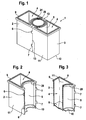
- FIG. 1 The representation according to FIG. 1 is a ready-made, on its top still open reagent cassette according to the present invention can be seen.
- a reagent cartridge 1 is formed by a first cassette part 2 forming a container and a second cassette part 3 also forming a container.
- the container-forming cassette parts 2, 3 are each provided with a curvature 5 at their facing sides.
- a container 20 (Beadflasche).
- the container 20 has on its upper side an annular surface 24 designed as a welding surface, just as the cassette parts 2, 3 forming the containers have a welding surface 9 on their upper side.
- the container 20 serves to receive a particle-containing reagent, while in cavities 4 of the container-forming cassette parts 2, 3 can be filled with reagents provided as liquid.
- the cassette parts 2, 3 or formed as a Bead bottle container 20 are welded to a film to protect the contents of the container 20 and the container-forming cassette parts 2, 3 against contamination.
- FIG. 1 shows, the cassette forming the container parts 2, 3 along a butt joint 13 to each other.
- the reagent cartridge 1 comprises a large-area side wall 11 and an end wall 12, which provide large planar surfaces for applying a label.
- the cassette parts 2, 3 forming the containers are preferably produced as injection-molded components, to which both the latching lugs 7 and the latching openings 9 and the bulges 5 can be formed in one operation on the respective cassette parts 2, 3.
- the representation according to FIG. 2 remove one of the two cassette parts of the reagent cassette.
- FIG. 2 The representation according to FIG. 2 It can be seen that the container part forming a cassette part 2 on the side of the curvature 5 has a semicircular enclosure 29 and a positioning aid 10.
- the positioning aid 10 is shown in the illustration FIG. 2 semicircular. In the region of the side wall 11 are the locking lugs 6, while on the opposite side wall, the locking lugs 7 are formed.
- a welding surface 9 Surrounding the cavity 4 of the cassette part 2, a welding surface 9 is formed on the upper side of the cassette part 2 forming a container.
- FIG. 3 In the illustration according to FIG. 3 is that in FIG. 2 shown, forming a container cassette part reproduced in section.
- FIG. 3 shows that the cavity 4 of the container forming a cassette part 2 is limited by a cavity floor 8, which is optimized in terms of dead volume. Under dead volume is understood in the present context, the reagent volume, which is no longer removable from the cavity 4 of the cassette part 2.
- the welding surface 9 at the top of the cassette forming a container part 2 is designed for a double seal, ie, the welding surface 9 may be stepped, so that a welding multiple superimposed films for closure (double sealing) of the cavity 4 of the container forming a cassette part 2 is possible ,
- the quarter circle in the representation according to FIG. 3 shown enclosure 29 and the positioning aid 10 also shown as a quarter circle serve the rotatable mounting of an in FIG. 3 not shown container 20, in which a particle-containing Reagent is added.
- On the rear side wall 11 of a container forming a cassette part 2 projecting locking lugs 7 are molded, which can be molded in the way of Kunststoffspritzg cashmaschinen in one operation during the preparation of the container formed as a cassette part 2.
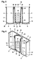
- Figure 4.1 shows a trained as Beadflasche container for receiving a particle-containing reagent.
- the container 20 comprises on its upper side an annular surface 24, on which a film can be welded on, in order to protect the interior against contamination after filling the container 20 with a particle-containing reagent.
- a positioning ring 22 is formed on the upper side of the container 20 designed as a bead bottle, which cooperates with the enclosure 29 arranged on the cassette parts 2, 3 designed as containers.
- a slotted plastic ring 21 is molded.
- the container 20 receiving the particle-containing reagent Beadflasche
- Beadflasche can be produced inexpensively in the course of the plastic injection molding in one operation.
- the positioning ring 22 Below the annular surface formed on the upper side of the container 20 (bead bottle) is the positioning ring 22. In the lower region of the container 20, this is provided on its inner side with a helical structure 23 in helical form.
- the spirally shaped helical structure 23 when intermittently rotated, produces a vertical flow in the cylindrical wall portion of the container 20 and a countercurrent vertical flow in the center of the container 20.
- a defined, radially extending flow is created at the bottom of the bottle which is very well suited is to resuspend the sedimented particles in the bottom area of the container 20.
- the shallow angle of the helical structure 23 with respect to the liquid surface enables gentle flow generation without cavitation phenomena and definitely prevents foaming inside the container 20 and damage to particles which may optionally be provided with a coating.
- the container 20 is limited by a bottle bottom 30. Below the bottom of the bottle, a slotted ring 21 is molded onto the container 20 (Beadflasche).
- the slotted ring comprises tabs 34 separated by slots, which are resilient are formed and which a coupling connection with a in Figure 4.2 enable coupling piece 31, not shown.
- the helical structure 23 extends in a helical shape along the two lower thirds of the container 20 (Beadflasche).
- the bottle bottom 30 is frustoconical.
- a slotted ring 21 is injection molded onto the container 20 for receiving a particle-containing reagent, the individual tabs 34 are separated by slits formed resiliently by slots to allow easy coupling with a coupling piece on a magazine.
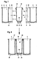
- FIG. 5 shows a prefabricated reagent cartridge, two cassette-forming cassette parts, and a container 20 received therebetween and containing a particle-containing reagent.
- FIG. 12 shows a prefabricated reagent cartridge, two cassette-forming cassette parts, and a container 20 received therebetween and containing a particle-containing reagent.
- FIG. 5 shows that the container containing the particle-containing reagent 20 is rotatably mounted between the respective container forming cassette parts 2 and 3.
- the container 20 (Beadflasche) is fixed on the one hand by the semicircular positioning 10 of the cartridge serving as a container parts 2, 3 above the slotted ring 21, and on the other hand by the above the positioning ring 22 adjacent semi-circular bezels 29.
- FIG. 5 is stored between the container-forming cassette parts 2, 3, a container 20 which is formed as a Bead bottle.
- the in FIG. 5 illustrated container 20 comprises a helical structure in helical form 23, which extends above the bottle bottom 30. From the in FIG.
- reagent cartridge 1 shows that in the assembled state, the reagent cartridge 3 has separate containers. These are the cavities 4 of the cassette part 2 and the cassette part 3 as well as the cavity of the container 20 for receiving the particle-containing reagent.
- the cavities 4 of the cassette parts 2 and 3 and the cavity of the container 20 are each bounded by a dead volume optimized bottom 8 and by a frustoconical bottom 30.
- both the container forming a cassette part 2 and the container forming a cassette part 3 each have a footprint.
- the slotted ring 21 formed on the container 20 for holding the particle-containing reagent likewise constitutes a flat base.
- the base surfaces of the cassette parts 2, 3 form or of the container 20 for receiving the particle-containing reagent, a flat bottom 28 of the reagent cartridge 1 in the assembled state 26.
- the slotted ring 21 has a plurality of resilient tabs 34 separated by slots.
- the curved surfaces of the container-forming cassette parts 2, 3 are identified, which form a cavity between the positioning 10 and the positioning ring 22 when the container-forming cassette parts 2, 3 are interlocked, ie plugged together.
- FIG. 6 From the illustration according to FIG. 6 is a sectional view of the in FIG. 5 shown reagent cassette in the assembled state.
- the container 20 rotatably mounted between the container forming cassette parts 2, 3 for receiving a particle-containing reagent 20 is supported by the bezels 29 and the positioning ring 22 which is molded on the container 20 in the upper region, while the rotatable mounting of the container 20 (Beadflasche ) takes place in the lower region by the semicircular positioning aids 10, which are molded onto the underside of the curved surfaces 5 of the cassette parts 2, 3.
- Each of the container-forming cassette parts 2, 3 comprises a dead volume-optimized bottom 8 (see illustration according to FIG. 3 ).
- a container 20 is inserted, which has a helical structure 23 in a helical shape on its inner side.
- a homogenization of the particle-containing reagent in the container 20 (Beadflasche), which offset by sedimentation concentration differences are compensated in the particle-containing reagent can, that is, a uniform particle distribution can be achieved within the particle-containing reagent.
- the end walls 12 of the reagent cartridge 1 in the assembled state 26 can be used for applying labels. The same applies to the lying between the end walls 12 side wall 11 of the reagent cartridge 1 in the assembled state 26.
- the cooperating detent openings 6 and locking lugs 7 along the butt joint 13 in the FIGS. 5 and 6 not shown.
- FIG. 7 are the individual containers from which the invention proposed reagent cassette is added to remove.
- the respective cassette parts 2, 3 and the container 20, which are shown in section, are joined together in the direction of the arrows.
- joining ie to move towards each other forming the container cassette parts 2, 3 snap the locking lugs 7 of a container forming a cassette part 2 in the latching openings 6 of the other, forming a container cassette part 3 a.
- the container 20 (bead bottle) for receiving a particle-containing reagent is aligned between the cassette parts 2, 3 to be joined so that the positioning ring 22 comes to bear below the enclosures 29 at the top of the two cassette parts 2.
- the two arranged at the bottom of the container cassette parts 2, 3 arranged positioning 10 enclose the container 20 above the slotted ring 21 having resiliently formed tabs 34.
- a rotatable mounting of the particle-containing reagent receiving container 20 (Beadflasche) in an in FIG. 8 achieved reagent cartridge 26 in the assembled state. Due to the formation of the footprint of the container forming a cassette part 2 and the other, a container forming cassette part 3 and the geometry of the slotted ring 21 in the assembled state 26 of the reagent cartridge 1, a flat bottom 28 is obtained. Due to the availability of the individual containers, ie the cassette parts 2 and 3 and the container 20 (Beadflasche), a filling of reagents and a cassette assembly can therefore take place independently of each other. As from the representations according to the FIGS. 7 and 8 it follows that a joining of the invention proposed reagent cartridge 1 by simply plugging together the components 2, 3 and 20, without further additional parts such as lids or neck-shaped joining elements would be required.
- a coupling piece can be removed with which the slotted ring is joined to the underside of the container containing the particle-containing reagent.
- Coupling piece 31 shown has a disk-shaped base 32 and a coupling head 33 formed on this.
- the slotted ring ie its resiliently formed tabs 34 on the coupling head 33 a.
- the resiliently formed, separated by slots tabs 34 enclose the coupling head 33 entirely.
- the engagement of the resiliently formed tabs 34 of the slotted ring 21 also assists the correct positioning of the container 20 within the reagent cartridge 1 and is advantageous for a low-friction bottle rotation within the reagent cartridge 1 in the assembled state 26.
- the engagement of the slotted ring 21 on the coupling piece 31 occurs Manual or automatic placement of a reagent magazine, as will be described below.
- FIG. 7 shown latching connection between the locking openings 6 and the locking lugs 7 on the container to be joined together forming cassette parts 2, 3 can also be configured so that a non-destructive release of the two cassette parts from each other is not possible.
- FIG. 10 shows a schematic view of a reagent magazine.
- the reagent magazine 40 essentially comprises a magazine plate 41, which is held by a central shaft 46.
- the magazine plate 41 rotates in the direction of rotation 42, indicated by the arrow identified by reference numeral 42.
- the reagent magazine 40 can also be formed in a matrix arrangement.
- the magazine plate 41 a plurality of coupling pieces 31 are embedded.
- the coupling pieces 31 are in turn driven by a drive shaft 45 which is connected via a gear 44 with a drive 43 in connection.
- Reagent cassettes 1 in the ready-made state 26 are positioned on the upper side of the magazine plate 41.
- the container-forming cassette parts 2, 3 are each connected via the snap fasteners 6, 7, latching openings 6 and locking lugs 7 releasably connected to each other, the clip connection between the container forming cassette parts 2, 3 can also be designed so that a non-destructive loosening not more is possible.
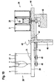
- FIG. 11 shows a schematic view of a reagent magazine in matrix arrangement.
- FIG. 11 Reagent cassettes are to be taken which have the first container-forming cassette part 2 (R1 bottle) and the second container-forming cassette part 3.
- the cassette parts 2 and 3 are connected to each other by a latching connection, given by the latching opening 6 and the latching lug 7 latching therein.
- the two in FIG. 11 Reagent cassettes recorded in a reagent magazine 47 in a matrix arrangement stand with their flat undersides 28 on a plate 48 of the reagent magazine 47 in a matrix arrangement.
- the reagent cartridges are closed at the top and contain individual containers 20 (bead bottles).
- the Beadflaschen 20 are secured by means of positioning rings 22 and coupled in the region of the bottle bottom 30 with the coupling piece 31.
- the Coupling piece 31 in turn is driven by a drive shaft 52 which is provided with a pulley or the like and, for example, by a toothed belt 51 can be driven.
- the timing belt 51 encloses another drive wheel, which in FIG. 11 on the left side of the figure shown reagent cartridge, consisting of the first container forming the cassette part 2 and the second container forming cassette part 3 is arranged.
- the toothed belt 51 is driven by a drive gear 50 of a drive 49 and offset by means of drive shafts 52, the coupling pieces 31, the coupled at the bottom in the region of the bottle bottom 30 by the coupling piece 31 container 20 (Beadflaschen) within the reagent cassettes in rotation.
- reagent cassette of which the middle container container 20 containing the coupling piece 31, the drive shaft 52, the toothed belt 51 and the drive 49 can be put into rotation.
- This can be similar in one operation as in the in FIG. 10 illustrated embodiment per reagent cartridge 1 prepare several reagents for further processing.
- the reagent to be homogenized which contains sedimenting particles is preferably received in the container 20 (bead bottle) which is driven via the coupling connection 31, 52.
- a plurality of reagent cartridges 1 in a matrix arrangement in the in FIG. 11 Reagent magazine 47 are treated in matrix arrangement.
Abstract
Description
Die Erfindung bezieht sich auf eine Reagenzkassette mit einem Reagenzbehälter für ein partikelhaltiges Reagenz, welche insbesondere geeignet ist zur noninvasiven Homogenisierung von beschichteten und sedimentierenden Partikeln sowie ein Magazin.The invention relates to a reagent cartridge with a reagent container for a particle-containing reagent, which is particularly suitable for noninvasive homogenization of coated and sedimenting particles and a magazine.
Diagnostische Assay-Systeme beinhalten in vielen Fällen die Verwendung von Partikeln in einer Flüssigkeit für den Ablauf von Reaktionen. Dabei handelt es sich um Verfahren zum Nachweis chemischer Bindungsreaktionen, zum Beispiel im Zusammenhang mit Antigenen oder Antikörpern. Für die korrekte Bearbeitung von Assays auf diesen Systemen ist es in der Regel erforderlich, dass die Partikel in den zugehörigen Behältern zum Zeitpunkt der Entnahme eine möglichst homogene Verteilung aufweisen. Eine homogene Partikelverteilung vermeidet zum Beispiel durch Sedimentationsprozesse auftretende Konzentrationsunterschiede zwischen aufeinanderfolgenden Entnahmen aus den Behältern.Diagnostic assay systems often involve the use of particles in a liquid for the course of reactions. These are methods for detecting chemical binding reactions, for example in connection with antigens or antibodies. For the correct processing of assays on these systems, it is usually necessary that the particles in the associated containers have the most homogeneous possible distribution at the time of removal. Homogeneous particle distribution avoids, for example, concentration differences between successive withdrawals from the containers due to sedimentation processes.
Im Bereich klinisch-diagnostischer Analysesysteme zur Homogenisierung von Partikeln wie zum Beispiel Magnetpartikel mit verbundenen partikelhaltigen Reagenzbehältern sind nachfolgende Verfahren bereits bekannt. Es werden rotierende Paddel eingesetzt. Derartig rotierbar aufgenommene Paddel sind aus
Den aus dem Stand der Technik bekannten Verfahren zur Homogenisierung von partikelhaltigen Reagenzien, zum Beispiel in Analysesystemen, die externe Aktoren wie zum Beispiel Paddel einsetzen, haften mehrere Nachteile an. Bei einem derartigen Verfahren zur Homogenisierung von partikelhaltigen Reagenzien handelt es sich um ein invasives Mischverfahren. Dies bedeutet, dass prinzipbedingt die Gefahr der Verschleppung zwischen verschiedenen partikelhaltigen Reagenzbehältern entsteht. Um der Gefahr der Verschleppung bei solchen Analysesystemen entgegenzuwirken, werden in diesen Systemen spezielle Waschstationen und Waschflüssigkeiten eingesetzt, mit denen der Gefahr der Verschleppung entgegengewirkt werden soll. Dies bedingt jedoch einen wesentlich höheren apparativen Aufwand bei solchen Analysesystemen. Bei Analysesystemen, die externe Aktoren wie zum Beispiel Paddel zur Homogenisierung von partikelhaltigen Reagenzien einsetzen, können mehrere Reagenzbehälter nur sequentiell prozessiert werden. Dies zieht wiederum lange Vorbereitungszeiten für einen Durchlauf nach sich, ferner sind Limitierungen in der Gestaltung des Gerätszyklus', des zeitlichen Zugriffs auf andere Reagenzbehälter und der Gerätetaktzeit vorgegeben. Gemäß dieser Verfahren homogenisierten partikelhaltigen Reagenzien tritt ferner bei abnehmendem Flüssigkeitsvolumen eine zunehmende Schaumbildung auf, was relativ hohe Reagentotvolumina nach sich zieht.The methods known from the prior art for the homogenization of particle-containing reagents, for example in analysis systems which use external actuators such as paddles, adhere to several disadvantages. Such a method for homogenizing particle-containing reagents is an invasive mixing method. This means that, in principle, there is the risk of carryover between different particle-containing reagent containers. To counteract the risk of carryover in such analysis systems, special washing stations and washing liquids are used in these systems, with which the risk of carryover is to be counteracted. However, this requires a much higher expenditure on equipment in such analysis systems. In analysis systems that use external actuators such as paddles for the homogenization of particle-containing reagents, multiple reagent containers can only be processed sequentially. This in turn entails long preparation times for a run, furthermore, limitations in the design of the device cycle, the temporal access to other reagent containers and the device cycle time are given. According to these methods, homogenized particulate-containing reagents also show increasing foam formation as the volume of liquid decreases, resulting in relatively high volumes of reagent depletion.
Invasiv arbeitende Ultraschallsysteme führen bei bestimmten Partikeltypen zu unzulässigen Veränderungen der Partikelbeschichtung. Ähnliches tritt bei invasiver Zugabe von Hilfsmitteln, wie sie etwa Glaskugeln darstellen, auf. Bei Systemen, bei denen zur Homogenisierung von partikelhaltigen Reagenzien radiale Innenflossen eingesetzt werden, tritt beim Durchmischen bestimmter Flüssigkeiten eine starke Schaumbildung ein; ferner verspritzt die Flüssigkeit, was höchst unbefriedigend ist.Invasive ultrasound systems lead to unacceptable particle coating changes for certain particle types. The same occurs with invasive addition of adjuvants, such as glass beads. In systems where radial inner fins are used for the homogenization of particle-containing reagents, strong foaming occurs when mixing certain liquids; Furthermore, the liquid splattered, which is highly unsatisfactory.
Bei den aus dem Stand der Technik gemäß
Dokument
Angesichts der oben skizzierten Nachteile der aus dem Stand der Technik bekannten Verfahren zur Homogenisierung von partikelhaltigen Reagenzien liegt der vorliegenden Erfindung die Aufgabe zugrunde, eine Homogenisierung von partikelbeladenen Reagenzien noninvasiv durch Rotation eines Behälters bereitzustellen.In view of the above-outlined disadvantages of the methods known from the prior art for the homogenization of particle-containing reagents, the object of the present invention is to provide a homogenization of particle-loaded reagents noninvasively by rotation of a container.
Erfindungsgemäß wird diese Aufgabe durch die Merkmale der Patentansprüche 1 und 3 gelöst.According to the invention this object is solved by the features of
Die Vorteile der erfindungsgemäß vorgeschlagenen Lösung liegen darin, dass durch die vorgeschlagene noninvasive Homogenisierung der partikelbeladenen Flüssigkeit das Verschleppungsrisiko definitiv ausgeschlossen werden kann. Es bedarf keiner Waschstationen. Ferner ist kein Waschfluid erforderlich und schließlich entsteht kein Flüssigkeitsabfall, der unter Wahrung der gesetzlichen Vorschriften zu entsorgen ist. Ferner lässt sich ein extrem niedriges Totvolumen erreichen, wodurch die Reagenz besser ausgenutzt werden kann, da eine Schaumbildung, wie zu den aus dem Stand der Technik bekannten Verfahren skizziert, unterbleibt. Die erfindungsgemäß vorgeschlagene Lösung erlaubt ferner größere Freiheitsgrade bei der Systemauslegung und bietet die Möglichkeit der Parallelisierung von Zugriffen im Reagenzbereich, da auf mehrere Reagenzien enthaltende Behälter einer Behältereinheit zugegriffen werden kann. Die Parallelisierung ermöglicht ferner erheblich kürzere Prozesszeiten für eine Homogenisierung, verglichen mit einer sequentiellen Bearbeitung.The advantages of the solution proposed according to the invention are that the carry-over risk can definitely be ruled out by the proposed noninvasive homogenization of the particle-laden liquid. There is no need for wash stations. Furthermore, no washing fluid is required and finally there is no liquid waste, which must be disposed of in compliance with legal requirements. Furthermore, an extremely low dead volume can be achieved, whereby the reagent can be better utilized, as foaming, as outlined in the known from the prior art method, omitted. The proposed solution according to the invention also allows greater degrees of freedom in the system design and offers the possibility of parallelizing accesses in the reagent area, since containers containing a plurality of reagents of a container unit can be accessed. The parallelization also allows much shorter process times for homogenization compared to sequential processing.
Ferner lässt sich durch die erfindungsgemäß vorgeschlagene Lösung eine Parallelisierung der Ersthomogenisierung für Reagenzkassetten erreichen; wegen möglicher Partikelsedimentation kann gerade die Ersthomogenisierung besonders zeitaufwendig sein. Vor der Ersthomogenisierung ist keine Liquid-level-detection erforderlich, weil für eine Mischung durch Flaschenrotation der Flüssigkeitspegel innerhalb der Reagenzkassetten nicht bekannt sein muss. Im Gegensatz dazu ist dies bei Mischvorgängen unter Einsatz von Rührpaddeln erforderlich, da ein nur unzureichendes Eintauchen der Rührpaddel eventuell zur Schaumbildung beiträgt und unerwünschte Spritzer erzeugt.Furthermore, can be achieved by the inventively proposed solution parallelization of Ersthomogenisierung for reagent cartridges; because of possible particle sedimentation just the Ersthomogenisierung can be particularly time consuming. Prior to the initial homogenization, no liquid level detection is required because for mixing by bottle rotation, the liquid level within the reagent cassettes need not be known. In contrast, this is necessary in mixing operations using stirring paddles, since insufficient immersion of the stirring paddle may contribute to foam formation and produce undesirable spatters.
Die erfindungsgemäß vorgeschlagene, zusammensteckbare Kassette bietet ferner den Vorteil, dass Deckelöffnungs- und Deckelschließabläufe beim Homogenisieren nunmehr entfallen können. Die erfindungsgemäß vorgeschlagene, mehrere Reagenzien aufnehmende Reagenzkassette ist mit einem Folienverschluss versehen, der Extrazyklen, wie das Öffnen beziehungsweise Schließen, vermeidet und somit die Durchsatzzeiten reduziert.The plug-in cassette proposed according to the invention also offers the advantage that lid opening and lid closing sequences can now be dispensed with during homogenization. The invention proposed, several reagents receiving reagent cassette is provided with a film closure, which avoids extra cycles, such as opening or closing, and thus reduces throughput times.
Die erfindungsgemäß vorgeschlagene zusammensteckbare Reagenzkassette stellt ferner ein kostengünstiges, in Großserie herstellbares Kunststoffbauteil dar, welches eine einfache Kassettenkonfektionierung ermöglicht. So lässt sich eine Kassettenkonfektionierung dadurch erzielen, dass zwei mit Wölbungen versehene Klipsteile unter Einschluss eines partikelbeladene Reagenzien enthaltenden Behälters einfach zusammengesteckt werden können. An den zusammensteckbaren Klipsteilen befinden sich große und plane Flächen, die das Etikettieren erheblich vereinfachen. Die einzelnen Klipsteile sowie der Behälter, welcher die partikelbeladene Flüssigkeit aufnimmt, können zeitlich unabhängig voneinander befüllt werden.The inventively proposed pluggable reagent cassette also represents a cost-effective, mass-produced plastic component, which allows a simple cassette assembly. Thus, a cassette assembly can be achieved in that two provided with buckling Klipsteile can be easily assembled, including a container containing particles laden reagents. The clip-on clip parts have large and flat surfaces that make labeling much easier. The individual clip parts and the container, which receives the particle-laden liquid, can be filled independently of each other in time.
Anhand der Zeichnung wird die Erfindung nachstehend eingehender beschrieben.With reference to the drawing, the invention will be described below in more detail.
Es zeigt:
- Figur 1
- eine zusammengefügte Reagenzkassette, zwei Kassettenteile umfassend, zwischen denen ein weiterer Behälter fixiert ist,
Figur 2- eines der beiden Klipsteile der Reagenzkassette in perspektivischer Ansicht,
Figur 3- das Klipsteil der Reagenzkassette gemäß
Figur 2 - Figur 4.1 bis 4.3
- Darstellungen eines partikelbeladene Reagenzien aufnehmenden Behälters mit Spiralstruktur,
Figur 5- eine konfektionierte Reagenzkassette, zwischen deren Klipsteilen der Behälter gemäß der
Figuren 4.1 bis 4.3 fixiert ist, Figur 6- einen Schnitt durch die konfektionierte Reagenzkassette gemäß der Darstellung in
Figur 5 Figur 7- die Einzelteile, aus denen die erfindungsgemäß vorgeschlagene Reagenzkassette zusammengesteckt wird,
Figur 8- die aus den Einzelteilen gemäß
Figur 7 Figur 9- ein Anschlussstück, über welches ein in der Reagenzkassette integrierter, eine partikelbeladene Flüssigkeit aufnehmender Behälter in Rotation versetzbar ist,
Figur 10- ein Mischmagazin mit einem Magazinteller, an dessen Oberseite die erfindungsgemäß vorgeschlagenen Reagenzkassetten aufgenommen sind und
Figur 11- eine perspektivische Ansicht der Vorrichtung gemäß
Figur 10 , teilweise aufgeschnitten.
- FIG. 1
- an assembled reagent cassette comprising two cassette parts, between which another container is fixed,
- FIG. 2
- one of the two Klipsteile the reagent cartridge in perspective view,
- FIG. 3
- the clip part of the reagent cartridge according to
FIG. 2 in half section, - FIGS. 4.1 to 4.3
- Representations of a particle loaded reagent receiving container with spiral structure,
- FIG. 5
- a ready-made reagent cassette, between the clip parts of the container according to the
Figures 4.1 to 4.3 is fixed, - FIG. 6
- a section through the ready-made reagent cartridge as shown in FIG
FIG. 5 . - FIG. 7
- the individual parts from which the reagent cassette proposed according to the invention is put together,
- FIG. 8
- according to the items
FIG. 7 assembled reagent cassette, - FIG. 9
- a connection piece via which a container, which is integrated in the reagent cassette and receives a particle-laden liquid, can be set in rotation,
- FIG. 10
- a mixing magazine with a magazine plate, at the top of which the reagent cassettes proposed according to the invention are accommodated and
- FIG. 11
- a perspective view of the device according to
FIG. 10 partially cut open.
Der Darstellung gemäß
Eine Reagenzkassette 1 wird durch einen ersten, einen Behälter bildenden Kassettenteil 2 sowie einen zweiten, ebenfalls einen Behälter bildenden Kassettenteil 3 gebildet. Die Behälter bildenden Kassettenteile 2, 3 sind an ihren einander zuweisenden Seiten jeweils mit einer Wölbung 5 versehen. Zwischen den Wölbungen 5 der Kassettenteile 2, 3 befindet sich ein Behälter 20 (Beadflasche). Der Behälter 20 weist an seiner Oberseite eine als Schweißfläche ausgebildete Ringfläche 24 auf, ebenso wie die die Behälter bildenden Kassettenteile 2, 3 an ihrer Oberseite eine Schweißfläche 9 aufweisen. Der Behälter 20 dient der Aufnahme einer partikelhaltigen Reagenz, während in Hohlräume 4 der Behälter bildenden Kassettenteile 2, 3 als Flüssigkeit beschaffene Reagenzien eingefüllt werden können. An ihren als Schweißflächen ausgebildeten Oberseiten 9, 24 können die Kassettenteile 2, 3 beziehungsweise der als Beadflasche ausgebildete Behälter 20 mit einer Folie verschweißt werden, um den Inhalt des Behälters 20 beziehungsweise der Behälter bildenden Kassettenteile 2, 3 gegen Kontamination zu schützen.A reagent cartridge 1 is formed by a
Wie aus der Darstellung gemäß
Der Darstellung gemäß
Der Darstellung gemäß
In der Darstellung gemäß
Aus der Darstellung gemäß
Die Schweißfläche 9 an der Oberseite des einen Behälter bildenden Kassettenteils 2 ist für eine Doppelversiegelung ausgelegt, d.h. die Schweißfläche 9 kann gestuft ausgebildet sein, so dass ein Aufschweißen mehrfach übereinanderliegender Folien zum Verschluss (Doppelversiegelung) des Hohlraumes 4 des einen Behälter bildenden Kassettenteils 2 möglich ist. Die als Viertelkreis in der Darstellung gemäß
Der Behälter 20 umfasst an seiner Oberseite eine Ringfläche 24, an welcher eine Folie aufschweißbar ist, um nach Befüllen des Behälters 20 mit einer partikelhaltigen Reagenz dessen Innenraum gegen Kontamination zu schützen. An der Oberseite des als Beadflasche ausgebildeten Behälters 20 ist insbesondere ein Positionierring 22 ausgebildet, welcher mit der an den als Behälter ausgebildeten Kassettenteilen 2, 3 angeordneten Einfassung 29 zusammenwirkt. Am Boden des Behälters 20 ist ein geschlitzter Kunststoffring 21 angespritzt. Auch der das partikelhaltige Reagenz aufnehmende Behälter 20 (Beadflasche) kann im Wege des Kunststoffspritzgießverfahrens in einem Arbeitsgang kostengünstig hergestellt werden.The
Aus der Darstellung gemäß
Unterhalb der an der Oberseite des Behälters 20 (Beadflasche) ausgebildeten Ringfläche befindet sich der Positionierring 22. Im unteren Bereich des Behälters 20 ist dieser an seiner Innenseite mit einer spiralförmigen Struktur 23 in Wendelform versehen. Die die Wendelform darstellende spiralförmige Struktur 23 erzeugt bei intermittierendem Drehen eine vertikale Strömung im zylindrischen Wandbereich des Behälters 20 sowie eine entgegenlaufende vertikale Strömung im Zentrum des Behälters 20. Zum Ausgleich entsteht am Flaschenboden eine definierte, sich in radiale Richtung erstreckende Strömung, die sehr gut geeignet ist, die im Bodenbereich des Behälters 20 sedimentierten Partikel zu resuspendieren. Der flache Winkel der spiralförmigen Struktur 23, bezogen auf die Flüssigkeitsoberfläche, ermöglicht eine schonende Strömungserzeugung ohne Kavitationserscheinungen und verhindert definitiv Schaumbildung im Inneren des Behälters 20 und eine Beschädigung von Partikeln, die optional mit einer Beschichtung versehen sein können.Below the annular surface formed on the upper side of the container 20 (bead bottle) is the
Der Behälter 20 wird durch einen Flaschenboden 30 begrenzt. Unterhalb des Flaschenbodens ist an den Behälter 20 (Beadflasche) ein geschlitzter Ring 21 angespritzt. Der geschlitzte Ring umfasst durch Schlitze voneinander getrennte Laschen 34, die federnd ausgebildet sind und welche eine Kupplungsverbindung mit einem in
Aus der perspektivisch dargestellten
Aus der Darstellung gemäß
Aus der Darstellung gemäß
Aus der Darstellung gemäß
Aus der Darstellung gemäß
Der zwischen den Behälter bildenden Kassettenteile 2, 3 drehbar gelagerte Behälter 20 zur Aufnahme einer partikelhaltigen Reagenz 20 wird durch die Einfassungen 29 und dem Positionierring 22, der am Behälter 20 angespritzt ist, im oberen Bereich gelagert, während die drehbare Lagerung des Behälters 20 (Beadflasche) im unteren Bereich durch die halbkreisförmig ausgebildeten Positionierhilfen 10 erfolgt, die an der Unterseite der gewölbten Flächen 5 der Kassettenteile 2, 3 angespritzt sind. Jedes der Behälter bildenden Kassettenteile 2, 3 umfasst einen Totvolumen-optimierten Boden 8 (vgl. Darstellung gemäß
In der Darstellung gemäß
Die Stirnwände 12 der Reagenzkassette 1 im konfektionierten Zustand 26 können zum Aufbringen von Etiketten genutzt werden. Gleiches gilt für die zwischen den Stirnwänden 12 liegende Seitenwand 11 der Reagenzkassette 1 im konfektionierten Zustand 26. Entlang der Stoßfuge 13 liegen die Behälter bildenden Kassettenteile 2, 3 aneinander an; aus Gründen der zeichnerischen Darstellungen sind die miteinander zusammenwirkenden Rastöffnungen 6 beziehungsweise Rastnasen 7 entlang der Stoßfuge 13 in den
Die jeweils im Schnitt dargestellten Kassettenteile 2, 3 sowie der Behälter 20 werden in Richtung der Pfeile miteinander gefügt. Beim Fügen, d.h. Aufeinanderzubewegen der Behälter bildenden Kassettenteile 2, 3 rasten die Rastnasen 7 des einen Behälter bildenden Kassettenteils 2 in die Rastöffnungen 6 des anderen, einen Behälter bildenden Kassettenteils 3 ein. Während des Fügens wird der Behälter 20 (Beadflasche) zur Aufnahme einer partikelhaltigen Reagenz so zwischen den miteinander zu fügenden Kassettenteilen 2, 3 ausgerichtet, dass der Positionierring 22 unterhalb der Einfassungen 29 an der Oberseite der beiden Kassettenteile 2 zur Anlage kommt. Die beiden am unteren Bereich der Behälter bildenden Kassettenteile 2, 3 angeordneten Positionierhilfen 10 umschließen den Behälter 20 oberhalb des geschlitzten Ringes 21, der federnd ausgebildete Laschen 34 aufweist. Dadurch wird eine drehbare Lagerung des eine partikelhaltige Reagenz aufnehmenden Behälters 20 (Beadflasche) in einer in
Der Darstellung gemäß
Das in
Der Vollständigkeit halber sei erwähnt, dass die in
Aus der Darstellung gemäß
Das Reagenzmagazin 40 umfasst im Wesentlichen einen Magazinteller 41, der von einer zentralen Welle 46 gehalten ist. Der Magazinteller 41 rotiert im Drehsinn 42, angedeutet durch den mit Bezugszeichen 42 identifizierten Pfeil. Anstelle des in
Aus der Darstellung gemäß
Der Darstellung gemäß
Mit der in
- 11
- Reagenzkassettereagent cartridge
- 22
-
erstes Behälter bildendes Kassettenteil
(R1-Flasche)first container forming cassette part
(R1-bottle) - 33
-
zweites Behälter bildendes Kassettenteil
(R2-Flasche)second container forming cassette part
(R2 bottle) - 44
- Hohlraumcavity
- 55
- gewölbte Seitearched side
- 66
- Rastöffnunglatching opening
- 77
- Rastnaselocking lug
- 88th
- HohlraumbodenRaised floor
- 99
- Schweißflächewelding surface
- 1010
- Positionierhilfepositioning
- 1111
- SeitenwandSide wall
- 1212
- Stirnwandbulkhead
- 1313
- Stoßfugebutt joint
- 2020
- Behälter (Beadflasche)Container (bead bottle)
- 2121
- geschlitzter Ringslotted ring
- 2222
- Positionierringpositioning
- 2323
- spiralförmige Struktur (Wendelform)helical structure (spiral shape)
- 2424
- Ringfläche (gestufte Schweißfläche)Ring surface (stepped welding surface)
- 2626
- konfektionierte Reagenzkassettepre-assembled reagent cassette
- 2727
- Oberseite ReagenzkassetteTop of the reagent cassette
- 2828
- ebene Unterseite Reagenzkassettelevel bottom reagent cartridge
- 2929
- Einfassungmount
- 3030
- Flaschenbodenbottle bottom
- 3131
- Kupplungsstückcoupling
- 3232
- Sockelbase
- 3333
- Kupplungskopfcoupling head
- 3434
-
federnde Laschen Schlitzring 21resilient tabs slit
ring 21
- 4040
- ReagenzmagazinReagenzmagazin
- 4141
- Magazintellermagazine plate
- 4242
- Drehsinnrotation
- 4343
- Antriebdrive
- 4444
- Getriebetransmission
- 4545
- Antriebswelle für KupplungsstückDrive shaft for coupling piece
- 4646
- zentrale Wellecentral shaft
- 4747
- Reagenzmagazin in MatrixanordnungReagent magazine in matrix arrangement
- 4848
- Teller in MatrixanordnungPlate in matrix arrangement
- 4949
- Antriebdrive
- 5050
- Antriebszahnraddrive gear
- 5151
- Zahnriementoothed belt
- 5252
- Antriebswelledrive shaft
Claims (13)
- Method for treating particle-charged reagents and reagents in liquid form received in containers (2, 3; 20) including the following method steps:a) Joining a reagent cartridge (1) from cartridge parts (2, 3) in such a way that a container (20) receiving a particle-charged reagent is mounted between the cartridge parts so as to be able to rotate,b) Providing a releasable coupling connection (21, 31) between the reagent cartridge, in an assembled state (26), and a magazine plate (41) containing a driven coupling piece (31), andc) Imparting a rotation movement to the container (20) receiving the particle-charged reagent via the coupling connection (21, 31) in order to homogenise the particle-charged reagent,characterised in that the reagent cartridge (1) in the assembled state (26) stands with its flat underside (28) on the magazine plate (41) during the rotation of the container (20).
- Method according to claim 1, characterised in that the container (20) receiving the particle-charged reagent is set in rotation relative to the reagent cartridge (1) in the assembled state (26).
- Cartridge for receiving containers (2, 3, 30) which respectively receive particle-charged and particle-free reagents, the container (20) containing the particle-charged reagent being rotatably received, the reagent cartridge (1) comprising cartridge parts (2, 3) which can be joined together, form containers and rotatably mount the container (20) receiving the particle-charged reagent in the joined-together state (20), characterised in that the container (26) is provided on its inside with a spiral-shaped structure (23) in helix form extending in the circumferential direction.
- Cartridge according to claim 3, characterised in that the container (20) is designed as a container for receiving particle-charged reagents.
- Cartridge according to claim 3, characterised in that the cartridge parts (2, 3) forming the containers can be locked together by means of a catch closure (6, 7).
- Cartridge according to claim 3, characterised in that the cartridge parts (2, 3) forming the containers have a weld face (9) on their top (27).
- Cartridge according to claim 6, characterised in that the cartridge parts (2, 3) forming the containers have on their top (27) a shoulder (29) and in the region of their flat underside (28) a positioning aid (10) with a semicircular recess for horizontally positioning the lower region of the container (20).
- Cartridge according to claim 3, characterised in that the cartridge parts (2, 3) forming the containers contain a hollow cavity base (8) with optimised dead volume.
- Cartridge according to claim 3, characterised in that the cartridge parts (2, 3) forming the containers are provided in each case with a curvature (5) on their sides facing one another.
- Cartridge according to claim 3, characterised in that the container (20) is provided at its top with an annular surface (24) designed as a weld face.
- Cartridge according to claim 3, characterised in that the container (20) is provided on its underside with a slotted ring (21) which serves as a releasable coupling.
- Cartridge according to claim 3, characterised in that the container (20) received rotatably in the cartridge parts (2, 3) forming the containers can be coupled to driven coupling pieces (31) let into a magazine plate (41).
- Cartridge according to claim 12, characterised in that the coupling pieces (31) on the magazine plate (41) are driven via drive shafts (45) and gears (44).
Applications Claiming Priority (2)
| Application Number | Priority Date | Filing Date | Title |
|---|---|---|---|
| DE10360526A DE10360526A1 (en) | 2003-12-22 | 2003-12-22 | Reagent cassette with reagent container for particle-containing reagent for its noninvasive homogenization |
| DE10360526 | 2003-12-22 |
Publications (3)
| Publication Number | Publication Date |
|---|---|
| EP1550498A2 EP1550498A2 (en) | 2005-07-06 |
| EP1550498A3 EP1550498A3 (en) | 2005-11-30 |
| EP1550498B1 true EP1550498B1 (en) | 2008-07-30 |
Family
ID=34559770
Family Applications (1)
| Application Number | Title | Priority Date | Filing Date |
|---|---|---|---|
| EP04029815A Not-in-force EP1550498B1 (en) | 2003-12-22 | 2004-12-16 | Reagent cartridge with reagent containers for reagents containing particles for their non-invasive homogenization |
Country Status (7)
| Country | Link |
|---|---|
| US (1) | US7790108B2 (en) |
| EP (1) | EP1550498B1 (en) |
| JP (1) | JP4106050B2 (en) |
| AT (1) | ATE402755T1 (en) |
| CA (1) | CA2490085C (en) |
| DE (2) | DE10360526A1 (en) |
| ES (1) | ES2311776T3 (en) |
Cited By (2)
| Publication number | Priority date | Publication date | Assignee | Title |
|---|---|---|---|---|
| US9513303B2 (en) | 2013-03-15 | 2016-12-06 | Abbott Laboratories | Light-blocking system for a diagnostic analyzer |
| US9993820B2 (en) | 2013-03-15 | 2018-06-12 | Abbott Laboratories | Automated reagent manager of a diagnostic analyzer system |
Families Citing this family (17)
| Publication number | Priority date | Publication date | Assignee | Title |
|---|---|---|---|---|
| JP4787026B2 (en) * | 2006-01-20 | 2011-10-05 | 凸版印刷株式会社 | Reaction vessel |
| FR2904114B1 (en) * | 2006-07-21 | 2008-10-17 | Biocode Hycel France Sa Sa | CARTRIDGE FOR REACTIVE PRODUCTS FOR USE IN ANALYTICAL APPARATUSES, CARRIER FOR RECEIVING THIS CARTRIDGE, AND ANALYSIS ASSEMBLY COMPRISING SAID CARTRIDGE AND HOLDER |
| US7731414B2 (en) * | 2007-02-08 | 2010-06-08 | Instrumentation Laboratory Company | Reagent cartridge mixing tube |
| WO2009090989A1 (en) * | 2008-01-15 | 2009-07-23 | Kyowa Medex Co., Ltd. | Reagent container |
| US20100159498A1 (en) * | 2008-12-19 | 2010-06-24 | Ritzen Kalle | Blood analyzer with a blood cell sedimentation control mechanism and method of use |
| JP2010202269A (en) * | 2009-03-05 | 2010-09-16 | Beckman Coulter Inc | Reaction card manufacturing device |
| JP6012728B2 (en) * | 2012-06-25 | 2016-10-25 | 協和メデックス株式会社 | Cassette and reagent set |
| US9535082B2 (en) | 2013-03-13 | 2017-01-03 | Abbott Laboratories | Methods and apparatus to agitate a liquid |
| US10058866B2 (en) | 2013-03-13 | 2018-08-28 | Abbott Laboratories | Methods and apparatus to mitigate bubble formation in a liquid |
| USD962471S1 (en) | 2013-03-13 | 2022-08-30 | Abbott Laboratories | Reagent container |
| USD978375S1 (en) | 2013-03-13 | 2023-02-14 | Abbott Laboratories | Reagent container |
| WO2014144759A1 (en) | 2013-03-15 | 2014-09-18 | Abbott Laboratories | Linear track diagnostic analyzer |
| US9897622B2 (en) | 2013-04-22 | 2018-02-20 | Hitachi High-Technologies Corporation | Automatic analyzer |
| US9724657B2 (en) * | 2013-10-22 | 2017-08-08 | Tyme, Inc. | High-speed centrifugal mixing devices and methods of use |
| USD848636S1 (en) | 2015-10-20 | 2019-05-14 | Roche Diagnostics Operations, Inc. | Reagent container |
| CN111812320B (en) * | 2020-07-28 | 2023-04-25 | 山东圣剑医学研究有限公司 | Detection kit of full-automatic immunoassay device |
| CN112973520A (en) * | 2021-02-07 | 2021-06-18 | 浙江交投丽新矿业有限公司 | A compound green equipment for mine ecological remediation |
Citations (1)
| Publication number | Priority date | Publication date | Assignee | Title |
|---|---|---|---|---|
| JPH10151125A (en) * | 1996-11-21 | 1998-06-09 | Corp Miyuki:Kk | Person discriminating system by dna |
Family Cites Families (20)
| Publication number | Priority date | Publication date | Assignee | Title |
|---|---|---|---|---|
| US3415361A (en) * | 1966-12-22 | 1968-12-10 | Miles Lab | Test device and container therefor |
| US2413094A (en) * | 1944-12-09 | 1946-12-24 | Remington Arms Co Inc | Metal treating apparatus |
| CH444126A (en) * | 1965-09-08 | 1967-09-30 | Inventa Ag | Device for the continuous implementation of chemical reactions in viscous liquids |
| EP0252632B1 (en) * | 1986-07-11 | 1994-08-31 | Beckman Instruments, Inc. | Reagent cartridge |
| JPS6415125A (en) * | 1987-07-07 | 1989-01-19 | Sanko Air Plant | Mixer for particulate matter |
| US5183638A (en) | 1989-12-04 | 1993-02-02 | Kabushiki Kaisha Nittec | Automatic immunity analysis apparatus with magnetic particle separation |
| ATE157459T1 (en) * | 1989-12-22 | 1997-09-15 | Alfa Biotech Spa | DEVICE FOR SELECTIVE STIRRING REACTION COMPONENTS |
| GB9020352D0 (en) * | 1990-09-18 | 1990-10-31 | Anagen Ltd | Assay or reaction apparatus |
| TW223593B (en) * | 1992-04-09 | 1994-05-11 | Hoffmann La Roche | |
| US5380487A (en) | 1992-05-05 | 1995-01-10 | Pasteur Sanofi Diagnostics | Device for automatic chemical analysis |
| US5428997A (en) | 1992-07-20 | 1995-07-04 | Pasteur Sanofi Diagnostics | Method of and device for fluid surface detection using an ultrasonic transducer |
| CA2132813A1 (en) | 1993-10-28 | 1995-04-29 | Ignatz Wolfgang Henzen | Reagent kit and analyzer suitable for using it |
| US5772962A (en) * | 1995-05-29 | 1998-06-30 | Hitachi, Ltd. | Analyzing apparatus using disposable reaction vessels |
| US5637962A (en) | 1995-06-09 | 1997-06-10 | The Regents Of The University Of California Office Of Technology Transfer | Plasma wake field XUV radiation source |
| US5609822A (en) * | 1995-07-07 | 1997-03-11 | Ciba Corning Diagnostics Corp. | Reagent handling system and reagent pack for use therein |
| DE19540877C2 (en) * | 1995-11-02 | 1998-02-26 | Byk Sangtec Diagnostica | Modular reagent cartridge |
| WO1997041445A1 (en) | 1996-04-26 | 1997-11-06 | Dade International Inc. | Method and apparatus for pre-treating samples in an automatic chemical analyzer |
| US5856194A (en) * | 1996-09-19 | 1999-01-05 | Abbott Laboratories | Method for determination of item of interest in a sample |
| US5795784A (en) | 1996-09-19 | 1998-08-18 | Abbott Laboratories | Method of performing a process for determining an item of interest in a sample |
| RU2191630C1 (en) * | 2001-06-09 | 2002-10-27 | Общество с ограниченной ответственностью "Кварц Т-2000" | Low-frequency acoustic generator |
-
2003
- 2003-12-22 DE DE10360526A patent/DE10360526A1/en not_active Withdrawn
-
2004
- 2004-12-13 CA CA2490085A patent/CA2490085C/en not_active Expired - Fee Related
- 2004-12-16 AT AT04029815T patent/ATE402755T1/en active
- 2004-12-16 ES ES04029815T patent/ES2311776T3/en active Active
- 2004-12-16 DE DE502004007729T patent/DE502004007729D1/en active Active
- 2004-12-16 EP EP04029815A patent/EP1550498B1/en not_active Not-in-force
- 2004-12-21 JP JP2004369506A patent/JP4106050B2/en not_active Expired - Fee Related
- 2004-12-22 US US11/021,071 patent/US7790108B2/en not_active Expired - Fee Related
Patent Citations (1)
| Publication number | Priority date | Publication date | Assignee | Title |
|---|---|---|---|---|
| JPH10151125A (en) * | 1996-11-21 | 1998-06-09 | Corp Miyuki:Kk | Person discriminating system by dna |
Cited By (3)
| Publication number | Priority date | Publication date | Assignee | Title |
|---|---|---|---|---|
| US9513303B2 (en) | 2013-03-15 | 2016-12-06 | Abbott Laboratories | Light-blocking system for a diagnostic analyzer |
| US9993820B2 (en) | 2013-03-15 | 2018-06-12 | Abbott Laboratories | Automated reagent manager of a diagnostic analyzer system |
| US10330691B2 (en) | 2013-03-15 | 2019-06-25 | Abbott Laboratories | Light-blocking system for a diagnostic analyzer |
Also Published As
| Publication number | Publication date |
|---|---|
| ES2311776T3 (en) | 2009-02-16 |
| JP4106050B2 (en) | 2008-06-25 |
| ATE402755T1 (en) | 2008-08-15 |
| CA2490085C (en) | 2011-02-15 |
| US7790108B2 (en) | 2010-09-07 |
| EP1550498A2 (en) | 2005-07-06 |
| US20050153426A1 (en) | 2005-07-14 |
| DE10360526A1 (en) | 2005-07-14 |
| DE502004007729D1 (en) | 2008-09-11 |
| JP2005181338A (en) | 2005-07-07 |
| EP1550498A3 (en) | 2005-11-30 |
| CA2490085A1 (en) | 2005-06-22 |
Similar Documents
| Publication | Publication Date | Title |
|---|---|---|
| EP1550498B1 (en) | Reagent cartridge with reagent containers for reagents containing particles for their non-invasive homogenization | |
| EP0871894B1 (en) | Modular reagent cartridge | |
| DE60030310T2 (en) | MIXING AND CASTING APPARATUS WITH ROTATABLE ARM AND ASSOCIATED VESSEL | |
| DE69831830T2 (en) | Disposable analyzer | |
| EP2030684B1 (en) | Device for providing pipettable substances | |
| WO2007020294A1 (en) | Device and method for the elimination of magnetic particles from a liquid | |
| CH654246A5 (en) | METHOD FOR CONNECTING AN END OF A TUBULAR CONTAINER BODY TO A CLOSING PART BY FRICTION WELDING. | |
| EP2514515B1 (en) | Method for mixing a first and a second component | |
| EP1859856A1 (en) | Mixing device with vacuum compartment | |
| EP2532428A2 (en) | Cartridge, centrifuge and method for mixing a first and a second component | |
| EP1474235A1 (en) | Sample preparation device and test device set based thereon | |
| DE19819447A1 (en) | Device and method for mixing and washing liquids and / or solids | |
| EP1944080A1 (en) | Device and method for moving a liquid in a cavity | |
| EP1465575A1 (en) | Welding shuttle for a bag | |
| EP3263215B1 (en) | Device with a flow cell with reagent storage | |
| DE2200730B2 (en) | DEVICE FOR MEASURING AND DISTRIBUTING A VARIETY OF SMALL QUANTITIES OF LIQUIDS | |
| WO2005002729A1 (en) | Use of a disposable container, microfluidic device and method for processing molecules | |
| DE102004030155A1 (en) | Dosing device and method for operating the same | |
| DE102008017083A1 (en) | Apparatus for equilibrium dialysis of liquids | |
| DE4428664C2 (en) | Container, arrangement and method for producing, storing and dispensing an individual formulation | |
| DE102016214069A1 (en) | Mixing head and method of operation | |
| EP3476489B1 (en) | Centrifuge insert | |
| DE3343846A1 (en) | Centrifuge rotor | |
| DE2659627A1 (en) | DEVICE FOR THE SEPARATION OF CHEMICAL SUBSTANCES WITH THE GENERATION OF STERILE SOLUTIONS | |
| EP3490699B1 (en) | Modular stirring mechanism |
Legal Events
| Date | Code | Title | Description |
|---|---|---|---|
| PUAI | Public reference made under article 153(3) epc to a published international application that has entered the european phase |
Free format text: ORIGINAL CODE: 0009012 |
|
| AK | Designated contracting states |
Kind code of ref document: A2 Designated state(s): AT BE BG CH CY CZ DE DK EE ES FI FR GB GR HU IE IS IT LI LT LU MC NL PL PT RO SE SI SK TR |
|
| AX | Request for extension of the european patent |
Extension state: AL BA HR LV MK YU |
|
| PUAL | Search report despatched |
Free format text: ORIGINAL CODE: 0009013 |
|
| AK | Designated contracting states |
Kind code of ref document: A3 Designated state(s): AT BE BG CH CY CZ DE DK EE ES FI FR GB GR HU IE IS IT LI LT LU MC NL PL PT RO SE SI SK TR |
|
| AX | Request for extension of the european patent |
Extension state: AL BA HR LV MK YU |
|
| RIC1 | Information provided on ipc code assigned before grant |
Ipc: 7B 65D 21/02 B Ipc: 7B 01F 15/00 B Ipc: 7B 01L 3/00 B Ipc: 7B 01F 9/00 B Ipc: 7B 01F 3/12 A |
|
| 17P | Request for examination filed |
Effective date: 20060112 |
|
| AKX | Designation fees paid |
Designated state(s): AT BE BG CH CY CZ DE DK EE ES FI FR GB GR HU IE IS IT LI LT LU MC NL PL PT RO SE SI SK TR |
|
| 17Q | First examination report despatched |
Effective date: 20060328 |
|
| GRAP | Despatch of communication of intention to grant a patent |
Free format text: ORIGINAL CODE: EPIDOSNIGR1 |
|
| RAP1 | Party data changed (applicant data changed or rights of an application transferred) |
Owner name: F. HOFFMANN-LA ROCHE AG Owner name: ROCHE DIAGNOSTICS GMBH |
|
| GRAS | Grant fee paid |
Free format text: ORIGINAL CODE: EPIDOSNIGR3 |
|
| GRAA | (expected) grant |
Free format text: ORIGINAL CODE: 0009210 |
|
| AK | Designated contracting states |
Kind code of ref document: B1 Designated state(s): AT BE BG CH CY CZ DE DK EE ES FI FR GB GR HU IE IS IT LI LT LU MC NL PL PT RO SE SI SK TR |
|
| REG | Reference to a national code |
Ref country code: GB Ref legal event code: FG4D Free format text: NOT ENGLISH |
|
| REG | Reference to a national code |
Ref country code: CH Ref legal event code: EP |
|
| REG | Reference to a national code |
Ref country code: CH Ref legal event code: NV Representative=s name: BOHEST AG |
|
| REF | Corresponds to: |
Ref document number: 502004007729 Country of ref document: DE Date of ref document: 20080911 Kind code of ref document: P |
|
| REG | Reference to a national code |
Ref country code: IE Ref legal event code: FG4D Free format text: LANGUAGE OF EP DOCUMENT: GERMAN |
|
| PG25 | Lapsed in a contracting state [announced via postgrant information from national office to epo] |
Ref country code: LT Free format text: LAPSE BECAUSE OF FAILURE TO SUBMIT A TRANSLATION OF THE DESCRIPTION OR TO PAY THE FEE WITHIN THE PRESCRIBED TIME-LIMIT Effective date: 20080730 Ref country code: IS Free format text: LAPSE BECAUSE OF FAILURE TO SUBMIT A TRANSLATION OF THE DESCRIPTION OR TO PAY THE FEE WITHIN THE PRESCRIBED TIME-LIMIT Effective date: 20081130 Ref country code: PT Free format text: LAPSE BECAUSE OF FAILURE TO SUBMIT A TRANSLATION OF THE DESCRIPTION OR TO PAY THE FEE WITHIN THE PRESCRIBED TIME-LIMIT Effective date: 20081230 Ref country code: NL Free format text: LAPSE BECAUSE OF FAILURE TO SUBMIT A TRANSLATION OF THE DESCRIPTION OR TO PAY THE FEE WITHIN THE PRESCRIBED TIME-LIMIT Effective date: 20080730 |
|
| REG | Reference to a national code |
Ref country code: ES Ref legal event code: FG2A Ref document number: 2311776 Country of ref document: ES Kind code of ref document: T3 |
|
| PG25 | Lapsed in a contracting state [announced via postgrant information from national office to epo] |
Ref country code: BG Free format text: LAPSE BECAUSE OF FAILURE TO SUBMIT A TRANSLATION OF THE DESCRIPTION OR TO PAY THE FEE WITHIN THE PRESCRIBED TIME-LIMIT Effective date: 20081030 Ref country code: SI Free format text: LAPSE BECAUSE OF FAILURE TO SUBMIT A TRANSLATION OF THE DESCRIPTION OR TO PAY THE FEE WITHIN THE PRESCRIBED TIME-LIMIT Effective date: 20080730 Ref country code: FI Free format text: LAPSE BECAUSE OF FAILURE TO SUBMIT A TRANSLATION OF THE DESCRIPTION OR TO PAY THE FEE WITHIN THE PRESCRIBED TIME-LIMIT Effective date: 20080730 |
|
| REG | Reference to a national code |
Ref country code: IE Ref legal event code: FD4D |
|
| PG25 | Lapsed in a contracting state [announced via postgrant information from national office to epo] |
Ref country code: EE Free format text: LAPSE BECAUSE OF FAILURE TO SUBMIT A TRANSLATION OF THE DESCRIPTION OR TO PAY THE FEE WITHIN THE PRESCRIBED TIME-LIMIT Effective date: 20080730 Ref country code: IE Free format text: LAPSE BECAUSE OF FAILURE TO SUBMIT A TRANSLATION OF THE DESCRIPTION OR TO PAY THE FEE WITHIN THE PRESCRIBED TIME-LIMIT Effective date: 20080730 Ref country code: DK Free format text: LAPSE BECAUSE OF FAILURE TO SUBMIT A TRANSLATION OF THE DESCRIPTION OR TO PAY THE FEE WITHIN THE PRESCRIBED TIME-LIMIT Effective date: 20080730 |
|
| PG25 | Lapsed in a contracting state [announced via postgrant information from national office to epo] |
Ref country code: CZ Free format text: LAPSE BECAUSE OF FAILURE TO SUBMIT A TRANSLATION OF THE DESCRIPTION OR TO PAY THE FEE WITHIN THE PRESCRIBED TIME-LIMIT Effective date: 20080730 Ref country code: SK Free format text: LAPSE BECAUSE OF FAILURE TO SUBMIT A TRANSLATION OF THE DESCRIPTION OR TO PAY THE FEE WITHIN THE PRESCRIBED TIME-LIMIT Effective date: 20080730 Ref country code: RO Free format text: LAPSE BECAUSE OF FAILURE TO SUBMIT A TRANSLATION OF THE DESCRIPTION OR TO PAY THE FEE WITHIN THE PRESCRIBED TIME-LIMIT Effective date: 20080730 |
|
| PLBE | No opposition filed within time limit |
Free format text: ORIGINAL CODE: 0009261 |
|
| STAA | Information on the status of an ep patent application or granted ep patent |
Free format text: STATUS: NO OPPOSITION FILED WITHIN TIME LIMIT |
|
| BERE | Be: lapsed |
Owner name: F. HOFFMANN-LA ROCHE A.G. Effective date: 20081231 Owner name: ROCHE DIAGNOSTICS G.M.B.H. Effective date: 20081231 |
|
| 26N | No opposition filed |
Effective date: 20090506 |
|
| PG25 | Lapsed in a contracting state [announced via postgrant information from national office to epo] |
Ref country code: MC Free format text: LAPSE BECAUSE OF NON-PAYMENT OF DUE FEES Effective date: 20081231 |
|
| PG25 | Lapsed in a contracting state [announced via postgrant information from national office to epo] |
Ref country code: BE Free format text: LAPSE BECAUSE OF NON-PAYMENT OF DUE FEES Effective date: 20081231 |
|
| PG25 | Lapsed in a contracting state [announced via postgrant information from national office to epo] |
Ref country code: SE Free format text: LAPSE BECAUSE OF FAILURE TO SUBMIT A TRANSLATION OF THE DESCRIPTION OR TO PAY THE FEE WITHIN THE PRESCRIBED TIME-LIMIT Effective date: 20081030 |
|
| PG25 | Lapsed in a contracting state [announced via postgrant information from national office to epo] |
Ref country code: PL Free format text: LAPSE BECAUSE OF FAILURE TO SUBMIT A TRANSLATION OF THE DESCRIPTION OR TO PAY THE FEE WITHIN THE PRESCRIBED TIME-LIMIT Effective date: 20080730 |
|
| PG25 | Lapsed in a contracting state [announced via postgrant information from national office to epo] |
Ref country code: HU Free format text: LAPSE BECAUSE OF FAILURE TO SUBMIT A TRANSLATION OF THE DESCRIPTION OR TO PAY THE FEE WITHIN THE PRESCRIBED TIME-LIMIT Effective date: 20090131 Ref country code: CY Free format text: LAPSE BECAUSE OF FAILURE TO SUBMIT A TRANSLATION OF THE DESCRIPTION OR TO PAY THE FEE WITHIN THE PRESCRIBED TIME-LIMIT Effective date: 20080730 Ref country code: LU Free format text: LAPSE BECAUSE OF NON-PAYMENT OF DUE FEES Effective date: 20081216 |
|
| PG25 | Lapsed in a contracting state [announced via postgrant information from national office to epo] |
Ref country code: TR Free format text: LAPSE BECAUSE OF FAILURE TO SUBMIT A TRANSLATION OF THE DESCRIPTION OR TO PAY THE FEE WITHIN THE PRESCRIBED TIME-LIMIT Effective date: 20080730 |
|
| PG25 | Lapsed in a contracting state [announced via postgrant information from national office to epo] |
Ref country code: GR Free format text: LAPSE BECAUSE OF FAILURE TO SUBMIT A TRANSLATION OF THE DESCRIPTION OR TO PAY THE FEE WITHIN THE PRESCRIBED TIME-LIMIT Effective date: 20081031 |
|
| PGFP | Annual fee paid to national office [announced via postgrant information from national office to epo] |
Ref country code: GB Payment date: 20131126 Year of fee payment: 10 Ref country code: AT Payment date: 20131126 Year of fee payment: 10 Ref country code: CH Payment date: 20131029 Year of fee payment: 10 |
|
| PGFP | Annual fee paid to national office [announced via postgrant information from national office to epo] |
Ref country code: ES Payment date: 20131211 Year of fee payment: 10 Ref country code: FR Payment date: 20131126 Year of fee payment: 10 Ref country code: IT Payment date: 20131217 Year of fee payment: 10 |
|
| PGFP | Annual fee paid to national office [announced via postgrant information from national office to epo] |
Ref country code: DE Payment date: 20131230 Year of fee payment: 10 |
|
| REG | Reference to a national code |
Ref country code: CH Ref legal event code: PCAR Free format text: NEW ADDRESS: HOLBEINSTRASSE 36-38, 4051 BASEL (CH) |
|
| REG | Reference to a national code |
Ref country code: DE Ref legal event code: R119 Ref document number: 502004007729 Country of ref document: DE |
|
| REG | Reference to a national code |
Ref country code: CH Ref legal event code: PL |
|
| REG | Reference to a national code |
Ref country code: AT Ref legal event code: MM01 Ref document number: 402755 Country of ref document: AT Kind code of ref document: T Effective date: 20141216 |
|
| GBPC | Gb: european patent ceased through non-payment of renewal fee |
Effective date: 20141216 |
|
| REG | Reference to a national code |
Ref country code: FR Ref legal event code: ST Effective date: 20150831 |
|
| PG25 | Lapsed in a contracting state [announced via postgrant information from national office to epo] |
Ref country code: DE Free format text: LAPSE BECAUSE OF NON-PAYMENT OF DUE FEES Effective date: 20150701 Ref country code: GB Free format text: LAPSE BECAUSE OF NON-PAYMENT OF DUE FEES Effective date: 20141216 Ref country code: LI Free format text: LAPSE BECAUSE OF NON-PAYMENT OF DUE FEES Effective date: 20141231 Ref country code: CH Free format text: LAPSE BECAUSE OF NON-PAYMENT OF DUE FEES Effective date: 20141231 |
|
| PG25 | Lapsed in a contracting state [announced via postgrant information from national office to epo] |
Ref country code: AT Free format text: LAPSE BECAUSE OF NON-PAYMENT OF DUE FEES Effective date: 20141216 Ref country code: FR Free format text: LAPSE BECAUSE OF NON-PAYMENT OF DUE FEES Effective date: 20141231 |
|
| PG25 | Lapsed in a contracting state [announced via postgrant information from national office to epo] |
Ref country code: IT Free format text: LAPSE BECAUSE OF NON-PAYMENT OF DUE FEES Effective date: 20141216 |
|
| REG | Reference to a national code |
Ref country code: ES Ref legal event code: FD2A Effective date: 20160127 |
|
| PG25 | Lapsed in a contracting state [announced via postgrant information from national office to epo] |
Ref country code: ES Free format text: LAPSE BECAUSE OF NON-PAYMENT OF DUE FEES Effective date: 20141217 |