EP1550477B1 - Stent and process for producing the same - Google Patents
Stent and process for producing the same Download PDFInfo
- Publication number
- EP1550477B1 EP1550477B1 EP03794087.1A EP03794087A EP1550477B1 EP 1550477 B1 EP1550477 B1 EP 1550477B1 EP 03794087 A EP03794087 A EP 03794087A EP 1550477 B1 EP1550477 B1 EP 1550477B1
- Authority
- EP
- European Patent Office
- Prior art keywords
- stent
- polymer
- mandrel
- matrix
- polymer film
- Prior art date
- Legal status (The legal status is an assumption and is not a legal conclusion. Google has not performed a legal analysis and makes no representation as to the accuracy of the status listed.)
- Expired - Fee Related
Links
Images


Classifications
-
- A—HUMAN NECESSITIES
- A61—MEDICAL OR VETERINARY SCIENCE; HYGIENE
- A61F—FILTERS IMPLANTABLE INTO BLOOD VESSELS; PROSTHESES; DEVICES PROVIDING PATENCY TO, OR PREVENTING COLLAPSING OF, TUBULAR STRUCTURES OF THE BODY, e.g. STENTS; ORTHOPAEDIC, NURSING OR CONTRACEPTIVE DEVICES; FOMENTATION; TREATMENT OR PROTECTION OF EYES OR EARS; BANDAGES, DRESSINGS OR ABSORBENT PADS; FIRST-AID KITS
- A61F2/00—Filters implantable into blood vessels; Prostheses, i.e. artificial substitutes or replacements for parts of the body; Appliances for connecting them with the body; Devices providing patency to, or preventing collapsing of, tubular structures of the body, e.g. stents
- A61F2/82—Devices providing patency to, or preventing collapsing of, tubular structures of the body, e.g. stents
- A61F2/86—Stents in a form characterised by the wire-like elements; Stents in the form characterised by a net-like or mesh-like structure
- A61F2/90—Stents in a form characterised by the wire-like elements; Stents in the form characterised by a net-like or mesh-like structure characterised by a net-like or mesh-like structure
-
- A—HUMAN NECESSITIES
- A61—MEDICAL OR VETERINARY SCIENCE; HYGIENE
- A61L—METHODS OR APPARATUS FOR STERILISING MATERIALS OR OBJECTS IN GENERAL; DISINFECTION, STERILISATION OR DEODORISATION OF AIR; CHEMICAL ASPECTS OF BANDAGES, DRESSINGS, ABSORBENT PADS OR SURGICAL ARTICLES; MATERIALS FOR BANDAGES, DRESSINGS, ABSORBENT PADS OR SURGICAL ARTICLES
- A61L31/00—Materials for other surgical articles, e.g. stents, stent-grafts, shunts, surgical drapes, guide wires, materials for adhesion prevention, occluding devices, surgical gloves, tissue fixation devices
- A61L31/08—Materials for coatings
- A61L31/10—Macromolecular materials
-
- A—HUMAN NECESSITIES
- A61—MEDICAL OR VETERINARY SCIENCE; HYGIENE
- A61L—METHODS OR APPARATUS FOR STERILISING MATERIALS OR OBJECTS IN GENERAL; DISINFECTION, STERILISATION OR DEODORISATION OF AIR; CHEMICAL ASPECTS OF BANDAGES, DRESSINGS, ABSORBENT PADS OR SURGICAL ARTICLES; MATERIALS FOR BANDAGES, DRESSINGS, ABSORBENT PADS OR SURGICAL ARTICLES
- A61L31/00—Materials for other surgical articles, e.g. stents, stent-grafts, shunts, surgical drapes, guide wires, materials for adhesion prevention, occluding devices, surgical gloves, tissue fixation devices
- A61L31/14—Materials characterised by their function or physical properties, e.g. injectable or lubricating compositions, shape-memory materials, surface modified materials
- A61L31/16—Biologically active materials, e.g. therapeutic substances
-
- B—PERFORMING OPERATIONS; TRANSPORTING
- B29—WORKING OF PLASTICS; WORKING OF SUBSTANCES IN A PLASTIC STATE IN GENERAL
- B29C—SHAPING OR JOINING OF PLASTICS; SHAPING OF MATERIAL IN A PLASTIC STATE, NOT OTHERWISE PROVIDED FOR; AFTER-TREATMENT OF THE SHAPED PRODUCTS, e.g. REPAIRING
- B29C41/00—Shaping by coating a mould, core or other substrate, i.e. by depositing material and stripping-off the shaped article; Apparatus therefor
- B29C41/02—Shaping by coating a mould, core or other substrate, i.e. by depositing material and stripping-off the shaped article; Apparatus therefor for making articles of definite length, i.e. discrete articles
- B29C41/04—Rotational or centrifugal casting, i.e. coating the inside of a mould by rotating the mould
- B29C41/042—Rotational or centrifugal casting, i.e. coating the inside of a mould by rotating the mould by rotating a mould around its axis of symmetry
-
- B—PERFORMING OPERATIONS; TRANSPORTING
- B29—WORKING OF PLASTICS; WORKING OF SUBSTANCES IN A PLASTIC STATE IN GENERAL
- B29C—SHAPING OR JOINING OF PLASTICS; SHAPING OF MATERIAL IN A PLASTIC STATE, NOT OTHERWISE PROVIDED FOR; AFTER-TREATMENT OF THE SHAPED PRODUCTS, e.g. REPAIRING
- B29C41/00—Shaping by coating a mould, core or other substrate, i.e. by depositing material and stripping-off the shaped article; Apparatus therefor
- B29C41/02—Shaping by coating a mould, core or other substrate, i.e. by depositing material and stripping-off the shaped article; Apparatus therefor for making articles of definite length, i.e. discrete articles
- B29C41/14—Dipping a core
-
- B—PERFORMING OPERATIONS; TRANSPORTING
- B29—WORKING OF PLASTICS; WORKING OF SUBSTANCES IN A PLASTIC STATE IN GENERAL
- B29C—SHAPING OR JOINING OF PLASTICS; SHAPING OF MATERIAL IN A PLASTIC STATE, NOT OTHERWISE PROVIDED FOR; AFTER-TREATMENT OF THE SHAPED PRODUCTS, e.g. REPAIRING
- B29C41/00—Shaping by coating a mould, core or other substrate, i.e. by depositing material and stripping-off the shaped article; Apparatus therefor
- B29C41/02—Shaping by coating a mould, core or other substrate, i.e. by depositing material and stripping-off the shaped article; Apparatus therefor for making articles of definite length, i.e. discrete articles
- B29C41/20—Shaping by coating a mould, core or other substrate, i.e. by depositing material and stripping-off the shaped article; Apparatus therefor for making articles of definite length, i.e. discrete articles incorporating preformed parts or layers, e.g. moulding inserts or for coating articles
-
- B—PERFORMING OPERATIONS; TRANSPORTING
- B29—WORKING OF PLASTICS; WORKING OF SUBSTANCES IN A PLASTIC STATE IN GENERAL
- B29C—SHAPING OR JOINING OF PLASTICS; SHAPING OF MATERIAL IN A PLASTIC STATE, NOT OTHERWISE PROVIDED FOR; AFTER-TREATMENT OF THE SHAPED PRODUCTS, e.g. REPAIRING
- B29C41/00—Shaping by coating a mould, core or other substrate, i.e. by depositing material and stripping-off the shaped article; Apparatus therefor
- B29C41/02—Shaping by coating a mould, core or other substrate, i.e. by depositing material and stripping-off the shaped article; Apparatus therefor for making articles of definite length, i.e. discrete articles
- B29C41/22—Making multilayered or multicoloured articles
-
- A—HUMAN NECESSITIES
- A61—MEDICAL OR VETERINARY SCIENCE; HYGIENE
- A61F—FILTERS IMPLANTABLE INTO BLOOD VESSELS; PROSTHESES; DEVICES PROVIDING PATENCY TO, OR PREVENTING COLLAPSING OF, TUBULAR STRUCTURES OF THE BODY, e.g. STENTS; ORTHOPAEDIC, NURSING OR CONTRACEPTIVE DEVICES; FOMENTATION; TREATMENT OR PROTECTION OF EYES OR EARS; BANDAGES, DRESSINGS OR ABSORBENT PADS; FIRST-AID KITS
- A61F2/00—Filters implantable into blood vessels; Prostheses, i.e. artificial substitutes or replacements for parts of the body; Appliances for connecting them with the body; Devices providing patency to, or preventing collapsing of, tubular structures of the body, e.g. stents
- A61F2/02—Prostheses implantable into the body
- A61F2/04—Hollow or tubular parts of organs, e.g. bladders, tracheae, bronchi or bile ducts
- A61F2/06—Blood vessels
- A61F2/07—Stent-grafts
- A61F2002/072—Encapsulated stents, e.g. wire or whole stent embedded in lining
-
- A—HUMAN NECESSITIES
- A61—MEDICAL OR VETERINARY SCIENCE; HYGIENE
- A61F—FILTERS IMPLANTABLE INTO BLOOD VESSELS; PROSTHESES; DEVICES PROVIDING PATENCY TO, OR PREVENTING COLLAPSING OF, TUBULAR STRUCTURES OF THE BODY, e.g. STENTS; ORTHOPAEDIC, NURSING OR CONTRACEPTIVE DEVICES; FOMENTATION; TREATMENT OR PROTECTION OF EYES OR EARS; BANDAGES, DRESSINGS OR ABSORBENT PADS; FIRST-AID KITS
- A61F2210/00—Particular material properties of prostheses classified in groups A61F2/00 - A61F2/26 or A61F2/82 or A61F9/00 or A61F11/00 or subgroups thereof
- A61F2210/0004—Particular material properties of prostheses classified in groups A61F2/00 - A61F2/26 or A61F2/82 or A61F9/00 or A61F11/00 or subgroups thereof bioabsorbable
-
- A—HUMAN NECESSITIES
- A61—MEDICAL OR VETERINARY SCIENCE; HYGIENE
- A61F—FILTERS IMPLANTABLE INTO BLOOD VESSELS; PROSTHESES; DEVICES PROVIDING PATENCY TO, OR PREVENTING COLLAPSING OF, TUBULAR STRUCTURES OF THE BODY, e.g. STENTS; ORTHOPAEDIC, NURSING OR CONTRACEPTIVE DEVICES; FOMENTATION; TREATMENT OR PROTECTION OF EYES OR EARS; BANDAGES, DRESSINGS OR ABSORBENT PADS; FIRST-AID KITS
- A61F2210/00—Particular material properties of prostheses classified in groups A61F2/00 - A61F2/26 or A61F2/82 or A61F9/00 or A61F11/00 or subgroups thereof
- A61F2210/0076—Particular material properties of prostheses classified in groups A61F2/00 - A61F2/26 or A61F2/82 or A61F9/00 or A61F11/00 or subgroups thereof multilayered, e.g. laminated structures
-
- A—HUMAN NECESSITIES
- A61—MEDICAL OR VETERINARY SCIENCE; HYGIENE
- A61F—FILTERS IMPLANTABLE INTO BLOOD VESSELS; PROSTHESES; DEVICES PROVIDING PATENCY TO, OR PREVENTING COLLAPSING OF, TUBULAR STRUCTURES OF THE BODY, e.g. STENTS; ORTHOPAEDIC, NURSING OR CONTRACEPTIVE DEVICES; FOMENTATION; TREATMENT OR PROTECTION OF EYES OR EARS; BANDAGES, DRESSINGS OR ABSORBENT PADS; FIRST-AID KITS
- A61F2250/00—Special features of prostheses classified in groups A61F2/00 - A61F2/26 or A61F2/82 or A61F9/00 or A61F11/00 or subgroups thereof
- A61F2250/0058—Additional features; Implant or prostheses properties not otherwise provided for
- A61F2250/0067—Means for introducing or releasing pharmaceutical products into the body
-
- A—HUMAN NECESSITIES
- A61—MEDICAL OR VETERINARY SCIENCE; HYGIENE
- A61L—METHODS OR APPARATUS FOR STERILISING MATERIALS OR OBJECTS IN GENERAL; DISINFECTION, STERILISATION OR DEODORISATION OF AIR; CHEMICAL ASPECTS OF BANDAGES, DRESSINGS, ABSORBENT PADS OR SURGICAL ARTICLES; MATERIALS FOR BANDAGES, DRESSINGS, ABSORBENT PADS OR SURGICAL ARTICLES
- A61L2300/00—Biologically active materials used in bandages, wound dressings, absorbent pads or medical devices
-
- B—PERFORMING OPERATIONS; TRANSPORTING
- B29—WORKING OF PLASTICS; WORKING OF SUBSTANCES IN A PLASTIC STATE IN GENERAL
- B29K—INDEXING SCHEME ASSOCIATED WITH SUBCLASSES B29B, B29C OR B29D, RELATING TO MOULDING MATERIALS OR TO MATERIALS FOR MOULDS, REINFORCEMENTS, FILLERS OR PREFORMED PARTS, e.g. INSERTS
- B29K2995/00—Properties of moulding materials, reinforcements, fillers, preformed parts or moulds
- B29K2995/0037—Other properties
- B29K2995/0059—Degradable
- B29K2995/006—Bio-degradable, e.g. bioabsorbable, bioresorbable or bioerodible
-
- B—PERFORMING OPERATIONS; TRANSPORTING
- B29—WORKING OF PLASTICS; WORKING OF SUBSTANCES IN A PLASTIC STATE IN GENERAL
- B29L—INDEXING SCHEME ASSOCIATED WITH SUBCLASS B29C, RELATING TO PARTICULAR ARTICLES
- B29L2031/00—Other particular articles
- B29L2031/753—Medical equipment; Accessories therefor
Definitions
- the present invention relates to a stent (intraluminal graft) which is recently used for intravascular therapy and surgical operation, particularly to enlarge a coronary stenosis, a carotid stenosis, a biliary duct, or an esophagus or to block an aneurysm and to a process for producing the same.
- a stent intraluminal graft
- ischemic heart diseases are generally treated by percutaneous transluminal cornary angioplasty (PTCA), that is, a procedure of introducing a balloon catheter to, for example, a narrowed part through a lumen of a blood vessel and, after that, inflating a balloon with liquid such as normal saline solution.
- PTCA percutaneous transluminal cornary angioplasty
- this procedure has a problem of high possibilities that an acute phase block of a coronary artery is caused and that the portion treated by PTCA is narrowed again (so-called post-PTCA restenosis).
- intraluminal graft called stent has been developed.
- the stent recently rapidly came into practical use and are in widespread use. According to recent data, nearly 75% of procedures using balloon catheters have been already replaced by procedures using stents.
- Stent matrix is an intraluminal graft which is implanted into a portion of a lumen to be treated through the lumen of a blood vessel or the like and is increased its diameter at the portion of the lumen to be treated so that the lumen is supported by action on the inside.
- the stent is mainly used in procedure for coronary artery so that the following description will be made mainly as to the procedure for coronary artery, the stent can be used for other lumens of human body such as biliary duct, esophagus, trachea, prostate, urinary duct, fallopian tube, aortic aneurysm, peripheral artery, renal artery, carotid artery, and cerebral blood vessel.
- stents will be used in many procedures including dilation of the narrowed portion, aneurysm embolization, cancer therapy, and the like, particularly that importance of microscopic stents will be increased according to the use in a field of cerebral surgery.
- a metallic stent matrix may thrombose a patient after several weeks from insertion of the metallic stent matrix. This is because the metallic stent itself is exposed to blood, resulting in adsorption of blood proteins such as fibrinogen and adherence or agglutination of blood platelets, thus forming thrombus. Further, thrombus may be formed because blood platelets are agglutinated on the convexes and concaves of a skeleton of the metallic stent matrix.
- JP H11-299901A discloses to coat an outer periphery of a metallic stent matrix with a flexible polymer film having a number of fine pores.
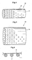
- Fig. 2 is a perspective view showing such a metallic stent matrix 10 having a mesh form to be used for a stent
- Fig. 3 is a perspective view showing the stent matrix of Fig. 2 in the expanded state 10'
- Fig. 4 is a perspective view showing a stent 20 comprising the stent matrix 10 of which outer periphery is coated with a flexible polymer film 19 having fine pores
- Fig. 5 is a perspective view showing the stent 20 in the expanded state
- endothelial cells In biological tissues, inner walls of blood vessels and the like, that is, portions to be directly in contact with blood are coated with cell layer so-called endothelial cells. Since the surfaces of the endothelial cells are covered by sugar and the endothelial cells secrete substances that inhibit activation of blood platelets such as prostaglandin, thrombus is hardly formed in biological tissues.
- the outer periphery of the metallic stent matrix is coated with a polymer film, thereby promoting proper endothelium formation with tissues and reducing thrombogenic property.
- the polymer film for coating the outer periphery of the stent matrix is formed as follows. That is, a mandrel for a cover strip is first impregnated in a polymer solution, then is dried, and is perforated. After that, the mandrel is pulled out, thereby forming a membrane cover strip (envelope-shaped cover film). A stent matrix is inserted into the envelope-shaped cover film in a state that the cover film is sufficiently expanded by sending air into the cover film. After that, the sending of air is stopped so as to shrink the cover film, thereby forming a covering membrane on the outer periphery of the stent matrix.
- the outer periphery of the metallic stent matrix is covered by a flexible polymer film having fine pores so as to engraft endothelium on the surface of the film on the outer periphery of the stent matrix, thereby reducing the causing of thrombus formation.
- the inner periphery of the stent matrix is not covered with the polymer film so that the metallic stent matrix is exposed. There is still a problem of causing thrombus, allergic to metal, stimulus of tissues due to metal, and rust development.
- the convexes disarrange bloodstream, facilitating the formation of thrombuses.
- the formed thrombuses exfoliate and move downstream (travels peripherad through the bloodstream) so as to cause infarction in small blood vessel on the downstream side or platelet-derived growth factor discharged from blood platelets in the thrombuses stimulate to cause thickening. Therefore, the problem of causing intimal thrombus is serious at this portion.
- the method of forming a polymer film as an outer covering membrane on the outer periphery of a stent matrix by inserting the stent matrix to an envelope-shaped cover film and shrinking the envelope-shaped cover film has the following problem. That is, as shown in Figs. 2 and 3 , the stent matrix 10 used in JP H11-299901A is formed of a cross-hatched lattice.
- the outer covering membrane is bonded at contact points between the polymer film and the respective stent struts 11 composing the mesh stent matrix 10 as shown in Fig. 6 . Accordingly, the integrity between the polymer film 19 and the stent matrix is poor.
- the contact points between the stent struts 11 and the polymer film 19 slide and move. That is, the position of the polymer film 19 covering the outer periphery of the stent matrix is shifted when the stent is expanded.
- the polymer film 19 has fine pores which are arranged to be spaced substantially equally.
- the purpose of the formation of fine pores is inhibiting formation of thrombuses and intimal thickening by grafting endothelial cells on the inner wall of the stent. Therefore, it is believed that the pores are formed at positions other than the position directly above the stent skeleton.
- the fine pores may be occluded by the stent struts. If the fine pores are occluded, the arrangement design of the fine pores becomes worthless.
- JP H11-299901A also describes that the polymer film is coated with biodegradable polymer or chemicals.
- the portions of the inner periphery of the polymer film where the struts of the mesh stent matrix are positioned are not coated with such a coating of the functioning agent.
- surfaces without coating of the functioning agent are exposed. The coating also becomes worthless.
- JP H11-299901A it is described that the adhesion of the cover strip to the outer periphery of the stent matrix 10 may be secured by heat-sealing of sending heated air during the coating of the stent matrix with the cover strip. Though this operation increases the adhesion at contact points between the polymer film 19 and the stent struts 11 composing the mesh stent matrix, it is impossible to coat entire surfaces of the stent struts 11 by the polymer film 19. Since the stent matrix is generally formed by laser beam machining of a metallic tube, shape edges of stent struts formed by cutting are rounded by chemical polishing or sonic treatment so that the surface of the stent matrix is generally mirror finish.
- US 6 309 413 discloses an endoluminal graft that is both expandable and supportive.
- a stent matrix made of a flexible material having shape memory property allowing deformation of the stent into an arch has been developed in order to allow the stent to be inserted into a bent vascular channel and a stent matrix which is deformable into an arch during expansion has been developed because there is a need that the stent can be deformed while increasing its diameter according to the shape of a part (for example, a part bent into an arch) of a vascular channel where the stent will be implanted.
- a stent of the invention comprises a tubular stent matrix of which diameter is extendable and a flexible polymer layer coating said stent matrix, and is characterized in that the polymer layer is closely attached to and covers the entire surface of the stent matrix.
- the stent Since the flexible polymer layer is attached to and covers the entire surface of the stent matrix not only the outer periphery of the stent matrix, the stent has no problem of causing allergic to metal, stimulus of tissues due to metal, and rust development. Since the inner periphery of the stent is a flat and smooth surface covered by the polymer layer without convexes and concaves so as not to disarrange bloodstream, the formation of thrombus can be inhibited well. In addition, there is no problem of drift between the stent matrix and the polymer layer during the expansion of the stent, thereby maintaining the positional relationship between the stent matrix and the polymer layer before and after the expansion of the stent.
- a process of producing a stent of the invention is a process of producing a stent having a tubular stent matrix of which diameter is extendable and flexible polymer films which are attached to both the inner periphery and the outer periphery of said stent matrix and have a plurality of fine pores formed therein, said process comprising: a step of forming the polymer film by impregnating a mandrel into a liquid resin material for forming the polymer film and pulling up the mandrel; and a step of equalizing the thickness of the polymer film by pulling up the mandrel in the vertical direction and controlling the pulling-up speed, characterized wherein said fine pores are formed after the polymer film is formed by laser machining and the pulling-up speed is gradually lowered.
- the flexible polymer films cover not only the outer periphery but also the inner periphery of the stent matrix in the stent produced by the process of the invention, the formation of thrombus can be inhibited well.
- the thickness of the polymer film can be equalized all over the length in the longitudinal direction of the stent (that is, the direction of pulling up the mandrel) by controlling the pulling-up seed of the mandrel.
- the thickness of the polymer film can be equalized all over the length in the longitudinal direction of the mandrel by gradually lowering the speed of pulling up the mandrel.
- a stent matrix composing a stent of the first invention is a tubular member having a length of from about 2 to 40 mm and a diameter of from about 1/10 to 1/2 of the length.
- the thickness of the stent matrix (wall thickness of the tubular member) is preferably from 11 to 2000 ⁇ m, more preferably from 51 to 500 ⁇ m, especially preferably from 101 to 300 ⁇ m.
- the stent matrix is preferably formed of a mesh so that the stent matrix can be flexibly expanded radially, particularly preferably, a cross-hatched lattice as shown in Fig. 2 in which the lattice extends in the helical direction.
- the stent matrix is preferably made of a biocompatible metal.
- a biocompatible metal include stainless steel, titanium, tantalum, aluminum, tungsten, nickel-titanium alloy, cobalt-chromium-nickel-iron alloy.
- the stent matrix is preferably subjected to heat treatment for shape memory.
- the heat treatment is conducted by converting the crystal structure of nitinol from martensite phase to austenite phase while the stent matrix is expanded, thereby memorizing the shape and giving self-expandability to the stent matrix.
- resins having excellent mechanical strength such as polyether ether ketone, aromatic polyamide, polyimide, and the like may be used for the base material of the stent.
- Suitable material of the flexible polymer layer is a high-molecular elastomer having high flexibility.
- a high-molecular elastomer include elastmers of polystyrene series, of polyolefin series, of polyester series, of polyamide series, of silicone series, of urethane series, of fluorocarbon resin series, and of natural rubber series, copolymers of these, and polymer alloys of these.
- a segmented polyurethane, a polymer of polyolefin series, and a polymer of silicone series are preferable, particularly, a segmented polyurethane having high flexibility and excellent mechanical strength is best.
- the segmented polyurethane polymer has a flexible polyether section as its soft segment and a section containing highly aromatic rings and urethane bonds as its hard segment, wherein the soft segment and the hard segment are subjected to phase separation to form a fine structure.
- the segmented polyurethane polymer is excellent in antithrombogenicity and is also excellent in properties such as strength and ductility so that it can be sufficiently expanded without being broken when the stent is expanded radially.
- the thickness ("d" in Fig. 1 as will be described later) of a polymer layer made of the segmented polyurethane polymer is preferably from 1 ⁇ m to 100 ⁇ m, particularly from 5 ⁇ m to 50 ⁇ m, especially from 20 ⁇ m to 50 ⁇ m.
- the polymer layer is preferably provided with a plurality of fine pores.
- the fine pores may be arranged in random order.
- the fine pores are formed to have substantially equal intervals therebetween.
- the phrase "substantially equal intervals" does not mean that the distances between fine pores are equal, but means that the fine pores are arranged at nearly regular intervals by a method of controlling the spaces between the fine pores. Accordingly, the arrangement with substantially equal intervals includes arrangements of oblique order, of circular order, of elliptic order, and the like which look random order at the first glance.
- the fine pores may have any size and any shape if the fine pore can allow passage of endothelial cells.
- the fine pores are preferably circular pores of which diameter is from 5 ⁇ m to 500 ⁇ m, preferably from 10 ⁇ m to 100 ⁇ m, more preferably from 20 ⁇ m to 100 ⁇ m. It should be understood that the fine pores may be pores of ellipse, square, rectangular, or other shape. This is true for the state before expansion. At a time when the stent is expanded and implanted in a lumen, the shape is varied from circle to ellipse and the diameter is also varied accordingly.
- the fine pores are aligned in a plurality of straight lines with intervals of from 51 ⁇ m to 10000 ⁇ m, preferably from 101 ⁇ m to 8000 ⁇ m, more preferably from 201 ⁇ m to 5000 ⁇ m.
- the plurality of straight lines are arranged in the axial direction of the stent with a predetermined constant angular interval from each other and are from 10 to 50 in number.
- the best diameter and interval of the fine pores are in subservient relationship.
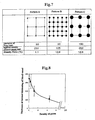
- the relationship can be easily understood by assuming the relationship as the density of pores in the polymer layer. That is, when substantially circular pores are arranged at nearly equal intervals just like three patterns shown in Fig. 7 , the density per unit area naturally depends on the diameter and the interval of the fine pores.
- Fig. 8 The relation between the density of pores and the thickness of the intimal thickening of a blood vessel caused by implantation of the stent into the blood vessel is shown in Fig. 8 .
- the preferable diameter and interval of fine pores are in relationship with the density of pores. It should be understood that, even with preferable density of pores, too small diameter of pores is not preferable because the growth of endothelial cells on the inner side of the stent must be poor and, on the other hand, too large diameter of pores is also not preferable because the strength of the polymer layer must be poor and ingression of endothelial tissues must be excessive.
- the polymer layer may be coated with a biodegradable polymer (bioabsorbable polymer).
- a biodegradable polymer include gelatine, poly-lactic acid, polyglycolic acid, caprolactone, lactic-glycol acid copolymer, polygioxisanone, and chitin.
- the biodegradable polymer may contain a therapeutic drug such as an antiplatelet drug, an antithrombotic drug, a growth accelerator, a growth inhibitor, and an immune-suppressing drug.
- the therapeutic drug is discharged into living body according to the degradation of the biodegradable polymer and thus provide effects of inhibiting formation of thrombus, inhibiting growth of smooth muscle cells so as to prevent constriction, inhibiting growth of cancerous cells, or promoting the growth of endothelial cells so as to achieve early formation of endothelium lining.
- Such a therapeutic drug examples include heparin, low-molecular heparin, hirudin, argatroban, formacolin, vapiprost, prostamoline, prostakilin homolog, dextran, D-phe-pro-arg chloromethyl ketone, dipyridamole, platelet receptor antagonist of glycoprotein, recombinant hirudin, thrombin inhibitor, vascular heptyne, angiotensin-converting enzyme inhibitor, steroid, fibrocyte growth factor antagonist, fish oil, omega 3 fatty acid, histamine, antagonist, HMG-CoA reductase inhibitor, seramin, serotonin blocker, thioprotease inhibitor, triazolopyrimidine, interferon, vascular endothelial growth factor (VEGF), rapamycin, and FK506.
- a therapeutic drug may be a statin drug having a function of melting plaque such as mevalotin, fuluvastatin, or the like.
- the polymer layer on the outer peripheral side of the stent may be coated with a lubricative substance in order to smooth the movement of the stent within a fine blood vessel in a human body.
- a lubricative substance include low-molecular hydrophilic substances such as glycerin, biocompatible substances such as hyaluronic acid and gelatine, and synthetic hydrophilic polymers such as polyethylene glycol, polyacrylamide, polydimethyl acrylamide, and polyvinylpyrrolidone.
- the stent of the invention in which the entire surface of the stent matrix is coated with the polymer layer wherein the polymer layer is closely attached to the entire surface of the stent matrix can be produced by the following process.
- the polymer solution may be a solution of polymer or a polymerized solution of monomer.
- a segmented polyurethane polymer solution prepared from an organic solvent such as dioxane or tetrahydrofuran may be used.
- a deacetonated, dealcoholized, or deoximated silicon rubber of condensation hardening type may be used.
- a coating containing the therapeutic drug is formed.
- the time and period when the therapeutic drug is discharged into the body can be controlled.
- the fine pores are formed in the stent intermediate by laser or the like after the mold removal.
- the formation of the coating of a biodegradable polymer or a lubricative polymer or the formation of fine pores by laser machining is performed in first.
- the description has been made here with a method of performing the formation of fine pores by laser machining after the coating formation.
- An embodiment of the present invention comprises the features of a process comprising: impregnating a mandrel in a polymer solution, pulling up the mandrel in the vertical direction so as to form an inner polymer layer, attaching a stent matrix to the mandrel having the inner polymer layer so that the stent matrix is overlaid onto the mandrel, then impregnating the mandrel with the stent matrix into the polymer solution, pulling up the mandrel with the stent matrix so as to form an outer polymer layer, and then pulling out the mandrel.
- a mandrel is impregnated into a polymer solution slowly not to entrap air bubbles, is then pulled up in the vertical direction, and is subjected to hardening treatment such as drying or ultraviolet irradiation, if necessary, so as to form an inner polymer layer.
- hardening treatment such as drying or ultraviolet irradiation, if necessary, so as to form an inner polymer layer.
- the drying is suitable as the hardening treatment.
- the ultraviolet irradiation or heat hardening is suitable as the hardening treatment.
- the stent matrix is attached to the mandrel having the inner polymer layer thus formed such that the stent matrix is overlaid onto the mandrel.
- the mandrel with the stent matrix attached is impregnated into the polymer solution slowly and is then pulled up in the vertical direction so as to form an outer polymer layer.
- the mandrel is pulled out, thereby producing a stent intermediate. Since the inner polymer layer and the outer polymer layer of the stent intermediate thus produced generally protrude from the both ends of the stent matrix, the excess protruding portions of the polymer layers are cut off.
- the mandrel is impregnated into the biodegradable polymer solution, i.e. the mandrel is subjected to the same coating treatment as mentioned above before the formation of the inner polymer layer or after the formation of the outer polymer layer.
- a coating containing the therapeutic drug is formed.
- the time and the period when the therapeutic drug is discharged into the body can be controlled. The same is true for the formation of a lubricative polymer layer.
- the fine pores are formed by laser machining to penetrate the inner polymer layer and the outer polymer layer before or after pulling out the mandrel.
- the mandrel is impregnated into an organic solvent which allows the polymer film to slightly swell preferably at a cubical expansion of 10% or less, thereby easily pulling out the mandrel from the stent intermediate.
- the kind of the organic solvent and the impregnating time depend on the material of the polymer film.
- the mandrel is preferably impregnated into lower alcohol, preferably methanol or ethanol, particularly into methanol preferably for 1-30 hours, particularly for 5-20 hours. This facilitates the drawing of the mandrel.
- the polymer film slightly swells so that the adhesion between the polymer film and the mandrel is reduced and that the lower alcohol has affinities both to the metal and the polymer layer and low surface tension so that the lower alcohol enters into a boundary face between the metallic mandrel and the inner polymer layer so as to reduce adherence between the surface of the mandrel and the polymer layer and improve the sliding property.
- a polymer layer 12 closely adheres and coats the entire surfaces of stent struts 11 composing a mesh stent matrix.
- the inner surface A of the stent is a flat and smooth surface of the polymer layer 12. Since this stent has absolutely no exposed surface of the metallic stent matrix, the problem of causing allergic to metal, stimulus of tissues due to metal, and rust development is solved. The problem of formation of thrombus is also solved. Particularly, the inner surface is a flat and smooth surface without convexes and concaves, thereby solving the formation of thrombus on convexes and concaves. In addition, there is no problem of displacement between the polymer layer and the stent matrix before and after the expansion of the stent.
- the coating thickness of the polymer layer represents the thickness of a part of the polymer layer 12 directly coating the stent strut 11, designated by "d" in Fig. 1 .
- a mesh stent matrix 10 having a diameter of 4 mm, a length of 20 mm, and a thickness of 0.2 mm shown in Fig. 2 was employed.
- Fig. 3 is a perspective view of the metallic stent matrix 10' after being expanded.
- the metallic stent matrix 10' in this state has a diameter of 8 mm, a length of 20 mm, and a thickness of 0.2 mm.
- a stent was produced by coating the entire surfaces of the metallic stent matrix 10 with a segmented polyurethane polymer layer.
- a mandrel made of SUS316 was impregnated into a polyurethane solution to form a polyurethane layer for coating a cylindrical outer surface of the mandrel.
- the metallic stent matrix which was slightly expanded was overlaid on the polyurethane layer with significant pressure.
- the mandrel with the stent matrix was impregnated into the polyurethane solution to form a coating so that both the inner and outer peripheries of the stent matrix were coated. After laser machining, the portions of the films protruding from the both ends were cut out.
- the mandrel with the stent intermediate was impregnated into ethanol and the stent intermediate was pulled out from the mandrel.
- the polyurethane solution was prepared by dissolving 10% by weight of Capdiomat (trade name) SPU: segmented polyurethane (available from Kontoron Cardiovascular Inc.) into a mixed solution of tetrahydrofuran and dioxane.
- Capdiomat trade name
- SPU segmented polyurethane
- the polyurethane polymer layer thus formed was perforated by excimer laser to have pores having a diameter of 100 ⁇ m such that the pores were substantially equally arranged at intervals of 200 ⁇ m. Pores aligned along 24 lines in total were formed by repeating a process of turning the stent intermediate at 15° in the circumferential direction after forming pores in a line in the longitudinal direction,
- Fig. 9 An X-ray transmission image of the stent thus obtained was taken by an X-ray microscope system (Model 1072, available from Skyscan).
- the X-ray transmission image is Fig. 9 .
- the coating thickness "d" was 25 ⁇ m.
- Fig. 9 corresponds to a portion IX of the stent shown in Fig. 4 , but shown as an enlarged image.
- the stent in which the entire surfaces of lattice-like struts 11 of the stent matrix are coated with the polyurethane polymer layer 12 with well adhesion. It is found that, even when the stent skeleton is moved according to the expansion of the stent matrix, the polyurethane polymer layer follows this movement, thus maintaining the positional relationship between the polymer layer and the stent. It is also found that the projecting structure of the stent struts as a factor of blocking bloodstream is laminated by the polymer film so as to have a flat and smooth surface.
- a coating of a polyurethane polymer film was formed only on the outer periphery of a stent matrix by the method described in JP H11-299901A . Fine pores were formed in the same manner as Example 1.
- An X-ray transmission image of the stent thus obtained was taken by the same way as Example 1.
- the X-ray transmission image is Fig. 10 . It is found that, in the stent, the polymer film covers and is in contact with the outer periphery of the stent matrix by points (lines) as shown in Fig. 6 , that is, the polymer film is fixed only by contact points. It is pointed out that the contact points are shifted by slide movement during the expansion of the stent.
- Fig. 11a shows Comparative Example 1
- Fig. 11b shows Example 1.
- Positioned outside the polymer layer is an existing intima and positioned inside the polymer layer is a neogenetic intima.
- the thickness of the intimal thickening of Example 1 ( Fig. 11b ) is thinner than that of Comparative example ( Fig. 11a ).
- thrombus may be easily formed around the struts so that platelet-derived growth factors and the like are discharged, resulting in intimal thickening.
- a mixed aqueous solution containing 5% of photoreactable gelatine of spiron benzophenone series, 2.5% of heparin, and 0.1% of silver powder was prepared.
- the stent produced in Comparative Example 1 was placed horizontally statically and the mixed solution was dropped to the inner wall of the stent at an amount of 20 ⁇ L per 1cm 2 .
- the dropped solution was stretched uniformly by a round bar made of PTFE and was exposed to light to fix a coating. This procedure was repeated twice.
- the stent of which inner wall was thus coated was expanded in air by a balloon catheter and, after that, was observed by an X-ray microscope. An X-ray transmission image taken of this stent is Fig. 13 .
- the stent of the invention since the polymer layer is closely attached to the entire surface of the stent matrix, excellent biocompatibility can be given to the stent, thereby preventing adverse effects to human tissues such as allergy and thrombus due to metal.
- the stent has no problem of displacement between the stent matrix and the polymer layer during the expansion of the stent.
- a coating of the biodegradable polymer may be formed by first obtaining a stent intermediate using a liquid base resin material such as the segmented polyurethane polymer and, after releasing the stent intermediate from the mold, impregnating the stent intermediate into a liquid resin material of the biodegradable polymer.
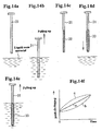
- a mandrel 31 is impregnated into a liquid resin material slowly not to entrap air bubbles, is then pulled up in the vertical direction, and is subjected to hardening treatment such as drying or ultraviolet irradiation, if necessary, so as to form an inner polymer film 32 as shown in Fig. 14c .
- the drying is suitable as the hardening treatment.
- the ultraviolet irradiation or heat hardening is suitable as the hardening treatment.
- the distribution of thickness of the inner polymer film 32 is made uniformly in the longitudinal direction of the mandrel 31 by gradually lowering the pulling-up speed of pulling up the mandrel.
- the pulling-up speed may be lowered in a linear fashion as indicated by a solid line "a” in Fig. 14f and may be lowered with decelerating speed as indicated by a double-dashed line "b".
- the pulling-up speed may be lowered such that degree of the decelerating speed may be gradually reduced as shown by dashed line C.
- the deceleration is preferably continuously conducted. This does not mean exclusion of stepwise deceleration.
- a stent matrix 33 is attached to the mandrel 31 having the inner polymer layer thus formed such that the stent matrix 33 is overlaid onto the mandrel 31.
- the stent matrix 33 is impregnated into the liquid resin material slowly and is pulled up in the vertical direction so as to form an outer polymer film. The pulling-up speed of this time is also controlled to have a pattern being gradually lowered in the same manner as the case of the inner polymer film 32.
- the mandrel 31 is pulled out, thereby producing a stent. Since the inner polymer film and the outer polymer film of the stent thus produced generally protrude from the both ends of the stent matrix 33, the excess protruding portions of the polymer films are cut off.
- the liquid resin material for forming the polymer films may be polymer solution or solution of a monomer.
- the polymer solution is preferable because polymerization is not required so that the formation of film is easy.
- a therapeutic drug may be contained into the biodegradable polymer solution.
- a coating layer of the biodegradable polymer containing the therapeutic drug can be formed.
- the time and the period when the therapeutic drug is discharged into the body can be controlled.
- fine pores are formed to penetrate the inner polymer film 32 and the outer polymer film before or after pulling out the mandrel 31.
- the fine pores are formed by laser machining.
- the mandrel for pulling out the mandrel from the stent thus obtained, the mandrel is impregnated into an organic solvent which allows the polymer film to slightly swell preferably at a cubical expansion of 10% or less, in the same manner as described in the first invention, thereby easily pulling out the mandrel from the stent.
- the kind of the organic solvent and the impregnating time depend on the material of the polymer film.
- the mandrel is preferably impregnated into lower alcohol, preferably methanol or ethanol, particularly into methanol preferably for 1-30 hours, particularly for 5-20 hours. This facilitates the drawing of the mandrel.
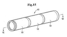
- a single stent matrix 33 is overlaid onto the mandrel 31 as shown in Fig. 14d in the aforementioned embodiment, two or more stent matrixes may be overlaid onto the mandrel with being slightly spaced apart from each other. In such a stent, a portion between the stent matrixes can be flexibly bent.
- a mesh stent matrix 10 having a diameter of 4 mm, a length of 20 mm, and a thickness of 0.2 mm shown in Fig. 2 was employed.
- Fig. 3 is a perspective view of the metallic stent matrix 10' after being expanded.
- the metallic stent matrix 10' in this state has a diameter of 8 mm, a length of 20 mm, and a thickness of 0.2 mm.
- a stent was produced by coating the inner periphery and the outer periphery of the metallic stent matrix 10 with segmented polyurethane polymer films. As described concretely, a mandrel having a diameter of 3.8 mm and made of stainless steel was impregnated into a polyurethane solution, was then pulled up, and was dried so as to form a cylindrical coating of the polyurethane having 30 ⁇ m. The metallic stent matrix which was slightly expanded was overlaid on the coating with significant pressure.
- the mandrel with the stent matrix was impregnated into the polyurethane solution, was then pulled up, and was dried so as to form a coating having a thickness of 50 ⁇ m so that the inner and outer peripheries of the stent matrix were coated. After laser machining, the portions of the films protruding from the both ends were cut out. The mandrel with the stent was impregnated into methanol for 12 hours and the stent was pulled out from the mandrel.
- the polyurethane solution was prepared by dissolving 10% by weight of segmented polyurethane, a trade name Capdiomat, (available from Kontoron Cardiovascular Inc.) into a mixed solution of tetrahydrofuran and dioxane.
- the speed of pulling up the mandrel was lowered in a linear fashion such that the initial speed was 10 mm/minute and the last speed was 5 mm/minute.
- Sections cut in the radial direction by high stainless steel were taken by a microscope.
- the thickness of the film at a section corresponding to an upper end of the mandrel during impregnation was 78.6 ⁇ m ⁇ 4.3 ⁇ m and the thickness at a section corresponding to a lower end of the mandrel was 80.1 ⁇ m ⁇ 2.4 ⁇ m. From this result, it was found that the film thus formed had a substantially uniform thickness.
- the films were perforated by excimer laser to have pores having a diameter of 100 ⁇ m such that the pores were substantially equally arranged at intervals of 200 ⁇ m. Pores aligned along 24 lines in total were formed by repeating a process of turning the cylindrical polymer film at 15° in the circumferential direction after forming pores in a line in the longitudinal direction.
- a stent was produced in the same manner as Example 4 except that the speed of pulling up the mandrel was constant at 10 mm/minute.
- the thickness of the film at radial sections in the same manner as Example 4, the thickness of the film at a section corresponding to an upper end of the mandrel during impregnation was 77.1 ⁇ m ⁇ 3.1 ⁇ m and the thickness of the film at a section corresponding to a lower end of the mandrel was 89.3 ⁇ m ⁇ 4.2 ⁇ m. From this result, it was found that thickness of the film thus formed was different in the vertical positional relationship. From this, it was noted that the thickness of the polymer film according to the present invention is uniform.
- the metallic stent provided with polymer film covering of the third invention can prevent adverse effects to human tissues such as thrombus due to metal.
- the polymer films are attached to the inner periphery and the outer periphery of the stent matrix, excellent biocompatibility can be given to the stent.
- the present invention can achieve homogenization of thickness of the polymer film.
Description
- The present invention relates to a stent (intraluminal graft) which is recently used for intravascular therapy and surgical operation, particularly to enlarge a coronary stenosis, a carotid stenosis, a biliary duct, or an esophagus or to block an aneurysm and to a process for producing the same.
- Conventionally, ischemic heart diseases are generally treated by percutaneous transluminal cornary angioplasty (PTCA), that is, a procedure of introducing a balloon catheter to, for example, a narrowed part through a lumen of a blood vessel and, after that, inflating a balloon with liquid such as normal saline solution. However, this procedure has a problem of high possibilities that an acute phase block of a coronary artery is caused and that the portion treated by PTCA is narrowed again (so-called post-PTCA restenosis). To solve the problem, intraluminal graft called stent has been developed. The stent recently rapidly came into practical use and are in widespread use. According to recent data, nearly 75% of procedures using balloon catheters have been already replaced by procedures using stents.
- Stent matrix is an intraluminal graft which is implanted into a portion of a lumen to be treated through the lumen of a blood vessel or the like and is increased its diameter at the portion of the lumen to be treated so that the lumen is supported by action on the inside. Though the stent is mainly used in procedure for coronary artery so that the following description will be made mainly as to the procedure for coronary artery, the stent can be used for other lumens of human body such as biliary duct, esophagus, trachea, prostate, urinary duct, fallopian tube, aortic aneurysm, peripheral artery, renal artery, carotid artery, and cerebral blood vessel. As the application field of stent expands more and more, it is expected that stents will be used in many procedures including dilation of the narrowed portion, aneurysm embolization, cancer therapy, and the like, particularly that importance of microscopic stents will be increased according to the use in a field of cerebral surgery.
- Through the spread of procedure using stent, restenosises have been dramatically prevented. On the other hand, however, since metallic stent matrixes are foreign substances in human body, a metallic stent matrix may thrombose a patient after several weeks from insertion of the metallic stent matrix. This is because the metallic stent itself is exposed to blood, resulting in adsorption of blood proteins such as fibrinogen and adherence or agglutination of blood platelets, thus forming thrombus. Further, thrombus may be formed because blood platelets are agglutinated on the convexes and concaves of a skeleton of the metallic stent matrix. Intimal thickening of a blood vessel due to cytokine discharged from blood platelets agglutinated on the periphery of the metallic stent matrix has been also pointed out as a problem. Accordingly,
JP H11-299901A -
Fig. 2 is a perspective view showing such ametallic stent matrix 10 having a mesh form to be used for a stent,Fig. 3 is a perspective view showing the stent matrix ofFig. 2 in the expanded state 10', andFig. 4 is a perspective view showing astent 20 comprising thestent matrix 10 of which outer periphery is coated with aflexible polymer film 19 having fine pores, andFig. 5 is a perspective view showing thestent 20 in the expanded state, - In biological tissues, inner walls of blood vessels and the like, that is, portions to be directly in contact with blood are coated with cell layer so-called endothelial cells. Since the surfaces of the endothelial cells are covered by sugar and the endothelial cells secrete substances that inhibit activation of blood platelets such as prostaglandin, thrombus is hardly formed in biological tissues. According to the stent disclosed in the aforementioned
JP H11-299901A - In
JP H11-299901A - (1) According to the stent of
JP H11-299901A JP H11-299901A - The method of forming a polymer film as an outer covering membrane on the outer periphery of a stent matrix by inserting the stent matrix to an envelope-shaped cover film and shrinking the envelope-shaped cover film has the following problem. That is, as shown in
Figs. 2 and 3 , thestent matrix 10 used inJP H11-299901A mesh stent matrix 10 by the aforementioned method, the outer covering membrane is bonded at contact points between the polymer film and therespective stent struts 11 composing themesh stent matrix 10 as shown inFig. 6 . Accordingly, the integrity between thepolymer film 19 and the stent matrix is poor. - Accordingly, when the stent matrix is expanded radially, the contact points between the
stent struts 11 and thepolymer film 19 slide and move. That is, the position of thepolymer film 19 covering the outer periphery of the stent matrix is shifted when the stent is expanded. - In
JP H11-299901A polymer film 19 has fine pores which are arranged to be spaced substantially equally. The purpose of the formation of fine pores is inhibiting formation of thrombuses and intimal thickening by grafting endothelial cells on the inner wall of the stent. Therefore, it is believed that the pores are formed at positions other than the position directly above the stent skeleton. When the polymer film is shifted relative to the stent matrix during expansion of the stent, however, the fine pores may be occluded by the stent struts. If the fine pores are occluded, the arrangement design of the fine pores becomes worthless. -
JP H11-299901A - In a paragraph [0040] of
JP H11-299901A stent matrix 10 may be secured by heat-sealing of sending heated air during the coating of the stent matrix with the cover strip. Though this operation increases the adhesion at contact points between thepolymer film 19 and thestent struts 11 composing the mesh stent matrix, it is impossible to coat entire surfaces of thestent struts 11 by thepolymer film 19. Since the stent matrix is generally formed by laser beam machining of a metallic tube, shape edges of stent struts formed by cutting are rounded by chemical polishing or sonic treatment so that the surface of the stent matrix is generally mirror finish. As well known, it is difficult to bond a resin material to a smooth surface of the metal. Similarly, it is not easy to bond the polymer film to the stent matrix. To cover the entire surfaces of the stent struts with the polymer film to increase the adhesion of thepolymer film 19 relative to the struts, it is required to melt the cover strip for even a moment and press the cover strip against the stent matrix. For this, it is necessary to send significantly hot air. Since the cover strip is a thin film having fine pores, however, the polymer film may not maintain its shape because of the hot air capable of melting the polymer film, resulting in bursting, breakage, defects of pin holes, cracks, or the like. -
US 6 309 413 discloses an endoluminal graft that is both expandable and supportive. - It is an object of the invention to overcome the problems of the stent of
JP H11-299901A - It is each object of the invention to provide a process of producing a stent having reduced thrombus formation.
- Recently, as the application field of stent has expanded more and more, a stent matrix made of a flexible material having shape memory property allowing deformation of the stent into an arch has been developed in order to allow the stent to be inserted into a bent vascular channel and a stent matrix which is deformable into an arch during expansion has been developed because there is a need that the stent can be deformed while increasing its diameter according to the shape of a part (for example, a part bent into an arch) of a vascular channel where the stent will be implanted.
- A stent of the invention comprises a tubular stent matrix of which diameter is extendable and a flexible polymer layer coating said stent matrix, and is characterized in that the polymer layer is closely attached to and covers the entire surface of the stent matrix.
- Since the flexible polymer layer is attached to and covers the entire surface of the stent matrix not only the outer periphery of the stent matrix, the stent has no problem of causing allergic to metal, stimulus of tissues due to metal, and rust development. Since the inner periphery of the stent is a flat and smooth surface covered by the polymer layer without convexes and concaves so as not to disarrange bloodstream, the formation of thrombus can be inhibited well. In addition, there is no problem of drift between the stent matrix and the polymer layer during the expansion of the stent, thereby maintaining the positional relationship between the stent matrix and the polymer layer before and after the expansion of the stent.
- A process of producing a stent of the invention is a process of producing a stent having a tubular stent matrix of which diameter is extendable and flexible polymer films which are attached to both the inner periphery and the outer periphery of said stent matrix and have a plurality of fine pores formed therein, said process comprising: a step of forming the polymer film by impregnating a mandrel into a liquid resin material for forming the polymer film and pulling up the mandrel; and a step of equalizing the thickness of the polymer film by pulling up the mandrel in the vertical direction and controlling the pulling-up speed, characterized wherein said fine pores are formed after the polymer film is formed by laser machining and the pulling-up speed is gradually lowered.
- Since the flexible polymer films cover not only the outer periphery but also the inner periphery of the stent matrix in the stent produced by the process of the invention, the formation of thrombus can be inhibited well.
- According to the invention, the thickness of the polymer film can be equalized all over the length in the longitudinal direction of the stent (that is, the direction of pulling up the mandrel) by controlling the pulling-up seed of the mandrel.
- If the pulling-up speed is constant, the thickness of the film becomes larger the lower the position of the mandrel pulled up is, because of liquid resin material falling from the above. In the third invention, the thickness of the polymer film can be equalized all over the length in the longitudinal direction of the mandrel by gradually lowering the speed of pulling up the mandrel.
-
-
Fig. 1 is a schematic sectional view of a stent of the invention, showing a state coated with a polymer layer; -
Fig. 2 is a perspective view of a stent matrix; -
Fig. 3 is a perspective view of the stent matrix in a state that its diameter is increased; -
Fig. 4 is a perspective view of a stent; -
Fig. 5 is a perspective view of the stent in a state that its diameter is increased; -
Fig. 6 is a schematic sectional view a stent ofJP H11-299901A -
Fig. 7 is an explanatory illustration showing relations of pattern of fine pores of a polymer layer relative to diameter, interval, and density of the fine pores; -
Fig. 8 is a graph showing a relation between density of pores of the polymer layer and the thickness of the intimal thickening of a blood vessel caused by implantation of a stent into the blood vessel; -
Fig. 9 is an X-ray transmission image of a stent of Example 1; -
Fig. 10 is an X-ray transmission image of a stent of Comparative Example 1; -
Fig. 11a is a photomicrograph of the stent after one month from implantation in Comparative Example landFig. 11b is a photomicrograph of the stent after one month from implantation in Example 1; -
Fig. 12 is a photomicrograph of a section of biological tissue where the stent is implanted in Comparative Example 1; -
Fig. 13 is an X-ray transmission image of the stent which is expanded after coating the inner wall of the stent in Comparative Example 2; -
Figs 14a-14f are explanatory illustrations of a process of the invention; -
Fig. 15 is a schematic perspective view of a stent according to an embodiment of the fifth invention; - Preferably, a stent matrix composing a stent of the first invention is a tubular member having a length of from about 2 to 40 mm and a diameter of from about 1/10 to 1/2 of the length. The thickness of the stent matrix (wall thickness of the tubular member) is preferably from 11 to 2000 µm, more preferably from 51 to 500 µm, especially preferably from 101 to 300 µm. The stent matrix is preferably formed of a mesh so that the stent matrix can be flexibly expanded radially, particularly preferably, a cross-hatched lattice as shown in
Fig. 2 in which the lattice extends in the helical direction. - The stent matrix is preferably made of a biocompatible metal. Examples of such a biocompatible metal include stainless steel, titanium, tantalum, aluminum, tungsten, nickel-titanium alloy, cobalt-chromium-nickel-iron alloy. When the stent matrix is made of nickel-titanium alloy, cobalt-chromiuln-nickel-iron alloy, or the like, the stent matrix is preferably subjected to heat treatment for shape memory. When the stent matrix is made of nitinol as one of nickel-titanium alloys, the heat treatment is conducted by converting the crystal structure of nitinol from martensite phase to austenite phase while the stent matrix is expanded, thereby memorizing the shape and giving self-expandability to the stent matrix. Other than metals, resins having excellent mechanical strength such as polyether ether ketone, aromatic polyamide, polyimide, and the like may be used for the base material of the stent.
- Suitable material of the flexible polymer layer is a high-molecular elastomer having high flexibility. Examples of such a high-molecular elastomer include elastmers of polystyrene series, of polyolefin series, of polyester series, of polyamide series, of silicone series, of urethane series, of fluorocarbon resin series, and of natural rubber series, copolymers of these, and polymer alloys of these. Among these, a segmented polyurethane, a polymer of polyolefin series, and a polymer of silicone series are preferable, particularly, a segmented polyurethane having high flexibility and excellent mechanical strength is best.
- The segmented polyurethane polymer has a flexible polyether section as its soft segment and a section containing highly aromatic rings and urethane bonds as its hard segment, wherein the soft segment and the hard segment are subjected to phase separation to form a fine structure. The segmented polyurethane polymer is excellent in antithrombogenicity and is also excellent in properties such as strength and ductility so that it can be sufficiently expanded without being broken when the stent is expanded radially.
- The thickness ("d" in
Fig. 1 as will be described later) of a polymer layer made of the segmented polyurethane polymer is preferably from 1 µm to 100 µm, particularly from 5 µm to 50 µm, especially from 20 µm to 50 µm. - The polymer layer is preferably provided with a plurality of fine pores. The fine pores may be arranged in random order. Preferably, the fine pores are formed to have substantially equal intervals therebetween. The phrase "substantially equal intervals" does not mean that the distances between fine pores are equal, but means that the fine pores are arranged at nearly regular intervals by a method of controlling the spaces between the fine pores. Accordingly, the arrangement with substantially equal intervals includes arrangements of oblique order, of circular order, of elliptic order, and the like which look random order at the first glance. The fine pores may have any size and any shape if the fine pore can allow passage of endothelial cells. The fine pores are preferably circular pores of which diameter is from 5 µm to 500 µm, preferably from 10 µm to 100 µm, more preferably from 20 µm to 100 µm. It should be understood that the fine pores may be pores of ellipse, square, rectangular, or other shape. This is true for the state before expansion. At a time when the stent is expanded and implanted in a lumen, the shape is varied from circle to ellipse and the diameter is also varied accordingly. The fine pores are aligned in a plurality of straight lines with intervals of from 51 µm to 10000 µm, preferably from 101 µm to 8000 µm, more preferably from 201 µm to 5000 µm. The plurality of straight lines are arranged in the axial direction of the stent with a predetermined constant angular interval from each other and are from 10 to 50 in number.
- It should be noted that the best diameter and interval of the fine pores are in subservient relationship. The relationship can be easily understood by assuming the relationship as the density of pores in the polymer layer. That is, when substantially circular pores are arranged at nearly equal intervals just like three patterns shown in
Fig. 7 , the density per unit area naturally depends on the diameter and the interval of the fine pores. - The relation between the density of pores and the thickness of the intimal thickening of a blood vessel caused by implantation of the stent into the blood vessel is shown in
Fig. 8 . - From
Fig. 8 , it is found that the preferable diameter and interval of fine pores are in relationship with the density of pores. It should be understood that, even with preferable density of pores, too small diameter of pores is not preferable because the growth of endothelial cells on the inner side of the stent must be poor and, on the other hand, too large diameter of pores is also not preferable because the strength of the polymer layer must be poor and ingression of endothelial tissues must be excessive. - The polymer layer may be coated with a biodegradable polymer (bioabsorbable polymer). Examples of such a biodegradable polymer include gelatine, poly-lactic acid, polyglycolic acid, caprolactone, lactic-glycol acid copolymer, polygioxisanone, and chitin.
- The biodegradable polymer may contain a therapeutic drug such as an antiplatelet drug, an antithrombotic drug, a growth accelerator, a growth inhibitor, and an immune-suppressing drug. The therapeutic drug is discharged into living body according to the degradation of the biodegradable polymer and thus provide effects of inhibiting formation of thrombus, inhibiting growth of smooth muscle cells so as to prevent constriction, inhibiting growth of cancerous cells, or promoting the growth of endothelial cells so as to achieve early formation of endothelium lining.
- Examples of such a therapeutic drug include heparin, low-molecular heparin, hirudin, argatroban, formacolin, vapiprost, prostamoline, prostakilin homolog, dextran, D-phe-pro-arg chloromethyl ketone, dipyridamole, platelet receptor antagonist of glycoprotein, recombinant hirudin, thrombin inhibitor, vascular heptyne, angiotensin-converting enzyme inhibitor, steroid, fibrocyte growth factor antagonist, fish oil, omega 3 fatty acid, histamine, antagonist, HMG-CoA reductase inhibitor, seramin, serotonin blocker, thioprotease inhibitor, triazolopyrimidine, interferon, vascular endothelial growth factor (VEGF), rapamycin, and FK506. Further, such a therapeutic drug may be a statin drug having a function of melting plaque such as mevalotin, fuluvastatin, or the like.
- The polymer layer on the outer peripheral side of the stent may be coated with a lubricative substance in order to smooth the movement of the stent within a fine blood vessel in a human body. Examples of such a lubricative substance include low-molecular hydrophilic substances such as glycerin, biocompatible substances such as hyaluronic acid and gelatine, and synthetic hydrophilic polymers such as polyethylene glycol, polyacrylamide, polydimethyl acrylamide, and polyvinylpyrrolidone.
- The stent of the invention in which the entire surface of the stent matrix is coated with the polymer layer wherein the polymer layer is closely attached to the entire surface of the stent matrix can be produced by the following process. [0039] The polymer solution may be a solution of polymer or a polymerized solution of monomer. As the polymer solution, a segmented polyurethane polymer solution prepared from an organic solvent such as dioxane or tetrahydrofuran may be used. As the polymerized solution of monomer, a deacetonated, dealcoholized, or deoximated silicon rubber of condensation hardening type may be used.
- By adding a therapeutic drug into the biodegradable polymer solution, a coating containing the therapeutic drug is formed. By adjusting the kind and the molecular weight of the biodegradable polymer and the thickness of the coating, the time and period when the therapeutic drug is discharged into the body can be controlled.
- As mentioned above, the fine pores are formed in the stent intermediate by laser or the like after the mold removal. There is no preference in whether the formation of the coating of a biodegradable polymer or a lubricative polymer or the formation of fine pores by laser machining is performed in first. However, the description has been made here with a method of performing the formation of fine pores by laser machining after the coating formation.
- An embodiment of the present invention comprises the features of a process comprising: impregnating a mandrel in a polymer solution, pulling up the mandrel in the vertical direction so as to form an inner polymer layer, attaching a stent matrix to the mandrel having the inner polymer layer so that the stent matrix is overlaid onto the mandrel, then impregnating the mandrel with the stent matrix into the polymer solution, pulling up the mandrel with the stent matrix so as to form an outer polymer layer, and then pulling out the mandrel.
- That is, a mandrel is impregnated into a polymer solution slowly not to entrap air bubbles, is then pulled up in the vertical direction, and is subjected to hardening treatment such as drying or ultraviolet irradiation, if necessary, so as to form an inner polymer layer. In case of using a solution of polymer as the polymer solution, the drying is suitable as the hardening treatment. In case of using a polymerized solution of monomer as the polymer solution, the ultraviolet irradiation or heat hardening is suitable as the hardening treatment.
- Then, the stent matrix is attached to the mandrel having the inner polymer layer thus formed such that the stent matrix is overlaid onto the mandrel. The mandrel with the stent matrix attached is impregnated into the polymer solution slowly and is then pulled up in the vertical direction so as to form an outer polymer layer. After the outer polymer layer is subjected to hardening treatment, the mandrel is pulled out, thereby producing a stent intermediate. Since the inner polymer layer and the outer polymer layer of the stent intermediate thus produced generally protrude from the both ends of the stent matrix, the excess protruding portions of the polymer layers are cut off.
- For forming a biodegradable polymer layer, the mandrel is impregnated into the biodegradable polymer solution, i.e. the mandrel is subjected to the same coating treatment as mentioned above before the formation of the inner polymer layer or after the formation of the outer polymer layer. By adding a therapeutic drug into the biodegradable polymer solution, a coating containing the therapeutic drug is formed. By adjusting the kind and the molecular weight of the biodegradable polymer and the thickness of the coating, the time and the period when the therapeutic drug is discharged into the body can be controlled. The same is true for the formation of a lubricative polymer layer.
- The fine pores are formed by laser machining to penetrate the inner polymer layer and the outer polymer layer before or after pulling out the mandrel.
- For pulling out the mandrel from the stent intermediate thus obtained, the mandrel is impregnated into an organic solvent which allows the polymer film to slightly swell preferably at a cubical expansion of 10% or less, thereby easily pulling out the mandrel from the stent intermediate. The kind of the organic solvent and the impregnating time depend on the material of the polymer film. For example, in case of using a segmented polyurethane resin for the polymer film, the mandrel is preferably impregnated into lower alcohol, preferably methanol or ethanol, particularly into methanol preferably for 1-30 hours, particularly for 5-20 hours. This facilitates the drawing of the mandrel. The reasons are considered, though remaining incompletely understood, that the polymer film slightly swells so that the adhesion between the polymer film and the mandrel is reduced and that the lower alcohol has affinities both to the metal and the polymer layer and low surface tension so that the lower alcohol enters into a boundary face between the metallic mandrel and the inner polymer layer so as to reduce adherence between the surface of the mandrel and the polymer layer and improve the sliding property.
- In the stent of the invention produced in the aforementioned manner, as shown in
Fig. 1 as its sectional view, apolymer layer 12 closely adheres and coats the entire surfaces of stent struts 11 composing a mesh stent matrix. The inner surface A of the stent is a flat and smooth surface of thepolymer layer 12. Since this stent has absolutely no exposed surface of the metallic stent matrix, the problem of causing allergic to metal, stimulus of tissues due to metal, and rust development is solved. The problem of formation of thrombus is also solved. Particularly, the inner surface is a flat and smooth surface without convexes and concaves, thereby solving the formation of thrombus on convexes and concaves. In addition, there is no problem of displacement between the polymer layer and the stent matrix before and after the expansion of the stent. - The coating thickness of the polymer layer represents the thickness of a part of the
polymer layer 12 directly coating thestent strut 11, designated by "d" inFig. 1 . - As the stent matrix, a
mesh stent matrix 10 having a diameter of 4 mm, a length of 20 mm, and a thickness of 0.2 mm shown inFig. 2 was employed. -
Fig. 3 is a perspective view of the metallic stent matrix 10' after being expanded. The metallic stent matrix 10' in this state has a diameter of 8 mm, a length of 20 mm, and a thickness of 0.2 mm. - A stent was produced by coating the entire surfaces of the
metallic stent matrix 10 with a segmented polyurethane polymer layer. As described concretely, a mandrel made of SUS316 was impregnated into a polyurethane solution to form a polyurethane layer for coating a cylindrical outer surface of the mandrel. The metallic stent matrix which was slightly expanded was overlaid on the polyurethane layer with significant pressure. The mandrel with the stent matrix was impregnated into the polyurethane solution to form a coating so that both the inner and outer peripheries of the stent matrix were coated. After laser machining, the portions of the films protruding from the both ends were cut out. The mandrel with the stent intermediate was impregnated into ethanol and the stent intermediate was pulled out from the mandrel. - The polyurethane solution was prepared by dissolving 10% by weight of Capdiomat (trade name) SPU: segmented polyurethane (available from Kontoron Cardiovascular Inc.) into a mixed solution of tetrahydrofuran and dioxane.
- The polyurethane polymer layer thus formed was perforated by excimer laser to have pores having a diameter of 100 µm such that the pores were substantially equally arranged at intervals of 200 µm. Pores aligned along 24 lines in total were formed by repeating a process of turning the stent intermediate at 15° in the circumferential direction after forming pores in a line in the longitudinal direction,
- An X-ray transmission image of the stent thus obtained was taken by an X-ray microscope system (Model 1072, available from Skyscan). The X-ray transmission image is
Fig. 9 . The coating thickness "d" was 25 µm.Fig. 9 corresponds to a portion IX of the stent shown inFig. 4 , but shown as an enlarged image. - As shown in
Fig. 1 , the stent in which the entire surfaces of lattice-like struts 11 of the stent matrix are coated with thepolyurethane polymer layer 12 with well adhesion. It is found that, even when the stent skeleton is moved according to the expansion of the stent matrix, the polyurethane polymer layer follows this movement, thus maintaining the positional relationship between the polymer layer and the stent. It is also found that the projecting structure of the stent struts as a factor of blocking bloodstream is laminated by the polymer film so as to have a flat and smooth surface. - A coating of a polyurethane polymer film was formed only on the outer periphery of a stent matrix by the method described in
JP H11-299901A Fig. 10 . It is found that, in the stent, the polymer film covers and is in contact with the outer periphery of the stent matrix by points (lines) as shown inFig. 6 , that is, the polymer film is fixed only by contact points. It is pointed out that the contact points are shifted by slide movement during the expansion of the stent. - These stents were grafted in carotid arteries of a rabbit. Observation was conducted after one month. The results are shown in Table 1,
Figs. 11a, 11b andFig. 12 . -
Fig. 11a shows Comparative Example 1 andFig. 11b shows Example 1. Positioned outside the polymer layer is an existing intima and positioned inside the polymer layer is a neogenetic intima. As apparent fromFigs. 11a, 11b , the thickness of the intimal thickening of Example 1 (Fig. 11b ) is thinner than that of Comparative example (Fig. 11a ). As shown inFig. 12 , since the stent struts project into blood stream in Comparative Example 1, thrombus may be easily formed around the struts so that platelet-derived growth factors and the like are discharged, resulting in intimal thickening. On the other hand, since the surface facing the bloodstream was a flat and smooth surface of the polymer layer in Example 1, the formation of thrombus was prevented.Table 1 Comparison of intimal thickening Thickness of intimal thickening (µm) Area ratio between neogenetic intima and existing intima (%) Comparative Example 1 304.6 (n=7) 302.9 Example 1 239.9 (n=7) 266.7 - A mixed aqueous solution containing 5% of photoreactable gelatine of spiron benzophenone series, 2.5% of heparin, and 0.1% of silver powder was prepared. The stent produced in Comparative Example 1 was placed horizontally statically and the mixed solution was dropped to the inner wall of the stent at an amount of 20 µL per 1cm2. The dropped solution was stretched uniformly by a round bar made of PTFE and was exposed to light to fix a coating. This procedure was repeated twice. The stent of which inner wall was thus coated was expanded in air by a balloon catheter and, after that, was observed by an X-ray microscope. An X-ray transmission image taken of this stent is
Fig. 13 . - From the above, it is found that portions where the stent struts existed before expansion were coated with no agent and sliding phenomenon between the stent struts and the polymer film was caused by the expansion so that the portions coated with no agent were exposed outside. The fine pores formed in Comparative Example 1 moved or slid on the polymer layer so that the fine pores were positioned behind the radiopaque stent struts as shown by arrows X. As a result, the fine pores were not observed in the X-ray transmission image of
Fig. 13 . This means that the fine pores were blocked. Therefore, it is pointed out that, since the diameter and intervals of pores which are strictly designed are varied by the expansion of the stent matrix as shown inFig. 8 , the density of pores is also varied, thus bringing about a problem of intimal thickening. - According to the stent of the invention, since the polymer layer is closely attached to the entire surface of the stent matrix, excellent biocompatibility can be given to the stent, thereby preventing adverse effects to human tissues such as allergy and thrombus due to metal. In addition, the stent has no problem of displacement between the stent matrix and the polymer layer during the expansion of the stent.
- A coating of the biodegradable polymer may be formed by first obtaining a stent intermediate using a liquid base resin material such as the segmented polyurethane polymer and, after releasing the stent intermediate from the mold, impregnating the stent intermediate into a liquid resin material of the biodegradable polymer.
- In the process of producing a stent of the invention, as shown in
Figs. 14a, 14b , amandrel 31 is impregnated into a liquid resin material slowly not to entrap air bubbles, is then pulled up in the vertical direction, and is subjected to hardening treatment such as drying or ultraviolet irradiation, if necessary, so as to form aninner polymer film 32 as shown inFig. 14c . - In case of using a solution of polymer as the liquid resin material, the drying is suitable as the hardening treatment. In case of using a monomer solution as the liquid resin material, the ultraviolet irradiation or heat hardening is suitable as the hardening treatment.
- In the invention, the distribution of thickness of the
inner polymer film 32 is made uniformly in the longitudinal direction of themandrel 31 by gradually lowering the pulling-up speed of pulling up the mandrel. The pulling-up speed may be lowered in a linear fashion as indicated by a solid line "a" inFig. 14f and may be lowered with decelerating speed as indicated by a double-dashed line "b". Alternatively, the pulling-up speed may be lowered such that degree of the decelerating speed may be gradually reduced as shown by dashed line C. Normally, it is preferable to take a deceleration pattern indicated by the solid line "a" or the double-dashed line "b". The deceleration is preferably continuously conducted. This does not mean exclusion of stepwise deceleration. - Then, as shown in
Fig. 14d , astent matrix 33 is attached to themandrel 31 having the inner polymer layer thus formed such that thestent matrix 33 is overlaid onto themandrel 31. As shown inFig. 14e , thestent matrix 33 is impregnated into the liquid resin material slowly and is pulled up in the vertical direction so as to form an outer polymer film. The pulling-up speed of this time is also controlled to have a pattern being gradually lowered in the same manner as the case of theinner polymer film 32. - After the outer polymer film is subjected to hardening treatment, the
mandrel 31 is pulled out, thereby producing a stent. Since the inner polymer film and the outer polymer film of the stent thus produced generally protrude from the both ends of thestent matrix 33, the excess protruding portions of the polymer films are cut off. - As mentioned above, the liquid resin material for forming the polymer films may be polymer solution or solution of a monomer. The polymer solution is preferable because polymerization is not required so that the formation of film is easy.
- A therapeutic drug may be contained into the biodegradable polymer solution. By applying this biodegradable polymer, a coating layer of the biodegradable polymer containing the therapeutic drug can be formed. By adjusting the kind and the molecular weight of the biodegradable polymer and the thickness of the coating, the time and the period when the therapeutic drug is discharged into the body can be controlled.
- After the outer polymer film is hardened, fine pores are formed to penetrate the
inner polymer film 32 and the outer polymer film before or after pulling out themandrel 31. The fine pores are formed by laser machining. - In the invention, for pulling out the mandrel from the stent thus obtained, the mandrel is impregnated into an organic solvent which allows the polymer film to slightly swell preferably at a cubical expansion of 10% or less, in the same manner as described in the first invention, thereby easily pulling out the mandrel from the stent. The kind of the organic solvent and the impregnating time depend on the material of the polymer film. For example, in case of using a segmented polyurethane resin for the polymer film, the mandrel is preferably impregnated into lower alcohol, preferably methanol or ethanol, particularly into methanol preferably for 1-30 hours, particularly for 5-20 hours. This facilitates the drawing of the mandrel.
- Though only a
single stent matrix 33 is overlaid onto themandrel 31 as shown inFig. 14d in the aforementioned embodiment, two or more stent matrixes may be overlaid onto the mandrel with being slightly spaced apart from each other. In such a stent, a portion between the stent matrixes can be flexibly bent. - As the stent matrix, a
mesh stent matrix 10 having a diameter of 4 mm, a length of 20 mm, and a thickness of 0.2 mm shown inFig. 2 was employed. -
Fig. 3 is a perspective view of the metallic stent matrix 10' after being expanded. The metallic stent matrix 10' in this state has a diameter of 8 mm, a length of 20 mm, and a thickness of 0.2 mm. - A stent was produced by coating the inner periphery and the outer periphery of the
metallic stent matrix 10 with segmented polyurethane polymer films. As described concretely, a mandrel having a diameter of 3.8 mm and made of stainless steel was impregnated into a polyurethane solution, was then pulled up, and was dried so as to form a cylindrical coating of the polyurethane having 30 µm. The metallic stent matrix which was slightly expanded was overlaid on the coating with significant pressure. The mandrel with the stent matrix was impregnated into the polyurethane solution, was then pulled up, and was dried so as to form a coating having a thickness of 50 µm so that the inner and outer peripheries of the stent matrix were coated. After laser machining, the portions of the films protruding from the both ends were cut out. The mandrel with the stent was impregnated into methanol for 12 hours and the stent was pulled out from the mandrel. - The polyurethane solution was prepared by dissolving 10% by weight of segmented polyurethane, a trade name Capdiomat, (available from Kontoron Cardiovascular Inc.) into a mixed solution of tetrahydrofuran and dioxane.
- The speed of pulling up the mandrel was lowered in a linear fashion such that the initial speed was 10 mm/minute and the last speed was 5 mm/minute. Sections cut in the radial direction by high stainless steel were taken by a microscope. As a result of measuring the thickness of the film at the sections, the thickness of the film at a section corresponding to an upper end of the mandrel during impregnation was 78.6 µm ± 4.3 µm and the thickness at a section corresponding to a lower end of the mandrel was 80.1 µm ± 2.4 µm. From this result, it was found that the film thus formed had a substantially uniform thickness.
- The films were perforated by excimer laser to have pores having a diameter of 100 µm such that the pores were substantially equally arranged at intervals of 200 µm. Pores aligned along 24 lines in total were formed by repeating a process of turning the cylindrical polymer film at 15° in the circumferential direction after forming pores in a line in the longitudinal direction.
- A stent was produced in the same manner as Example 4 except that the speed of pulling up the mandrel was constant at 10 mm/minute. As a result of measuring the thickness of the film at radial sections in the same manner as Example 4, the thickness of the film at a section corresponding to an upper end of the mandrel during impregnation was 77.1 µm ± 3.1 µm and the thickness of the film at a section corresponding to a lower end of the mandrel was 89.3 µm ± 4.2 µm. From this result, it was found that thickness of the film thus formed was different in the vertical positional relationship. From this, it was noted that the thickness of the polymer film according to the present invention is uniform.
- The metallic stent provided with polymer film covering of the third invention can prevent adverse effects to human tissues such as thrombus due to metal. Particularly, since the polymer films are attached to the inner periphery and the outer periphery of the stent matrix, excellent biocompatibility can be given to the stent. The present invention can achieve homogenization of thickness of the polymer film.
Claims (10)
- A process of producing a stent (20) having a tubular stent matrix (33) of which diameter is extendable and flexible polymer films (12), (19), (32) which are attached to both the inner periphery and the outer periphery of said stent matrix (33) and have a plurality of fine pores formed therein, said process comprising:a step of forming the polymer film (12), (19), (32) by impregnating a mandrel (31) into a liquid resin material for forming the polymer film (12), (19), (32) and pulling up the mandrel (31); anda step of equalizing the thickness of the polymer film (12), (19), (32) by pulling up the mandrel (31) in the vertical direction and controlling the pulling-up speed;characterised in that
the pulling-up speed of the mandrel (31) is gradually lowered; and wherein
said fine pores are formed by laser machining after the polymer film (12), (19), (32) is formed. - A process of producing a stent (20) as claimed in claim 1, wherein the polymer film (12), (19), (32) is made of a base resin material only.
- A process of producing a stent (20) as claimed in claim 1, wherein the polymer film (12), (19), (32) comprises a base layer made of a base resin material and a layer of a biodegradable polymer covering the surface of the base layer.
- A process of producing a stent (20) as claimed in claim 2 or 3, wherein the liquid base resin material is a solution of segmented polyurethane polymer.
- A process of producing a stent (20) as claimed in claim 1, wherein said fine pores are spaced from each other at intervals of from 51 to 10000 µm and each pore has a diameter of from 5 to 500 µm.
- A process of producing a stent (20) as claimed in any one of claims 1 through 5, wherein the thickness of said polymer films (12), (19), (32) is from 10 to 100 µm.
- A process of producing a stent (20) as claimed in any one of claims 1 through 6, wherein said stent matrix (33) is a mesh metallic member (10).
- A process of producing a stent 20 as claimed in any one of claims 3 through 7, wherein said biodegradable polymer contains a drug.
- A process of producing a stent (20) as claimed in claim 8, wherein said drug is selected from a group consisting of heparin, low-molecular heparin, hirudin, argatroban, formacolin, vapiprost, prostamoline, prostakilin homolog, dextran, D-phe-pro-arg chloromethyl ketone, dipyridamole, platelet receptor antagonist of glycoprotein, recombinant hirudin, thrombin inhibitor, vascular heptyne, angiotensin-converting enzyme inhibitor, steroid, fibrocyte growth factor antagonist, fish oil, omega 3 fatty acid, histamine, antagonist, HMG-CoA reductase inhibitor, seramin, serotonin blocker, thioprotease inhibitor, triazolopyrimidine, interferon, vascular endothelial, growth factor (VEGF), rapamycin, FK506, mevalotin, and fuluvastatin.
- A stent (20) produced by a process claimed in any one of claims through 9.
Applications Claiming Priority (17)
| Application Number | Priority Date | Filing Date | Title |
|---|---|---|---|
| JP2002243871 | 2002-08-23 | ||
| JP2002243871 | 2002-08-23 | ||
| JP2003109167 | 2003-04-14 | ||
| JP2003109168 | 2003-04-14 | ||
| JP2003109167A JP2004313320A (en) | 2003-04-14 | 2003-04-14 | Method of manufacturing stent |
| JP2003109168A JP4325259B2 (en) | 2003-04-14 | 2003-04-14 | Stent manufacturing method |
| JP2003109169A JP4395553B2 (en) | 2003-04-14 | 2003-04-14 | Stent manufacturing method |
| JP2003109169 | 2003-04-14 | ||
| JP2003169510A JP2005000518A (en) | 2003-06-13 | 2003-06-13 | Manufacturing method for stent, and stent |
| JP2003169510 | 2003-06-13 | ||
| JP2003201201A JP2005040219A (en) | 2003-07-24 | 2003-07-24 | Stent |
| JP2003201201 | 2003-07-24 | ||
| JP2003201836A JP5463513B2 (en) | 2002-08-23 | 2003-07-25 | Stent |
| JP2003201836 | 2003-07-25 | ||
| JP2003286901 | 2003-08-05 | ||
| JP2003286901A JP2005052419A (en) | 2003-08-05 | 2003-08-05 | Stent |
| PCT/JP2003/010496 WO2004022150A1 (en) | 2002-08-23 | 2003-08-20 | Stent and process for producing the same |
Publications (3)
| Publication Number | Publication Date |
|---|---|
| EP1550477A1 EP1550477A1 (en) | 2005-07-06 |
| EP1550477A4 EP1550477A4 (en) | 2010-11-17 |
| EP1550477B1 true EP1550477B1 (en) | 2015-11-04 |
Family
ID=31982815
Family Applications (1)
| Application Number | Title | Priority Date | Filing Date |
|---|---|---|---|
| EP03794087.1A Expired - Fee Related EP1550477B1 (en) | 2002-08-23 | 2003-08-20 | Stent and process for producing the same |
Country Status (6)
| Country | Link |
|---|---|
| US (1) | US8591782B2 (en) |
| EP (1) | EP1550477B1 (en) |
| CN (1) | CN1678366B (en) |
| AU (1) | AU2003257604A1 (en) |
| TW (1) | TW200404526A (en) |
| WO (1) | WO2004022150A1 (en) |
Cited By (1)
| Publication number | Priority date | Publication date | Assignee | Title |
|---|---|---|---|---|
| US9585668B2 (en) | 2004-03-31 | 2017-03-07 | Merlin Md Pte Ltd | Medical device |
Families Citing this family (156)
| Publication number | Priority date | Publication date | Assignee | Title |
|---|---|---|---|---|
| US6955661B1 (en) * | 1999-01-25 | 2005-10-18 | Atrium Medical Corporation | Expandable fluoropolymer device for delivery of therapeutic agents and method of making |
| US20060177416A1 (en) | 2003-10-14 | 2006-08-10 | Medivas, Llc | Polymer particle delivery compositions and methods of use |
| WO2003002243A2 (en) | 2001-06-27 | 2003-01-09 | Remon Medical Technologies Ltd. | Method and device for electrochemical formation of therapeutic species in vivo |
| US8246673B2 (en) * | 2002-09-19 | 2012-08-21 | Exstent Limited | External support for a blood vessel |
| EP1539035B1 (en) * | 2002-09-19 | 2011-08-17 | Exstent Limited | Improvements relating to stents |
| US7637942B2 (en) | 2002-11-05 | 2009-12-29 | Merit Medical Systems, Inc. | Coated stent with geometry determinated functionality and method of making the same |
| US7959671B2 (en) | 2002-11-05 | 2011-06-14 | Merit Medical Systems, Inc. | Differential covering and coating methods |
| US7344559B2 (en) * | 2003-08-25 | 2008-03-18 | Biophan Technologies, Inc. | Electromagnetic radiation transparent device and method of making thereof |
| US20050055085A1 (en) * | 2003-09-04 | 2005-03-10 | Rivron Nicolas C. | Implantable medical devices having recesses |
| US8021331B2 (en) * | 2003-09-15 | 2011-09-20 | Atrium Medical Corporation | Method of coating a folded medical device |
| EP1682210A4 (en) | 2003-11-07 | 2009-11-04 | Merlin Md Pte Ltd | Implantable medical devices with enhanced visibility, mechanical properties and biocompatibility |
| JP2007512107A (en) * | 2003-11-20 | 2007-05-17 | アルヴィオラス,インコーポレイテッド | Differential coating and coating method |
| US20050119723A1 (en) * | 2003-11-28 | 2005-06-02 | Medlogics Device Corporation | Medical device with porous surface containing bioerodable bioactive composites and related methods |
| US7632299B2 (en) * | 2004-01-22 | 2009-12-15 | Boston Scientific Scimed, Inc. | Medical devices |
| US8034096B2 (en) * | 2004-03-31 | 2011-10-11 | Cook Medical Technologies Llc | Stent-graft with graft to graft attachment |
| US8500751B2 (en) * | 2004-03-31 | 2013-08-06 | Merlin Md Pte Ltd | Medical device |
| US8715340B2 (en) * | 2004-03-31 | 2014-05-06 | Merlin Md Pte Ltd. | Endovascular device with membrane |
| US7601382B2 (en) * | 2004-08-05 | 2009-10-13 | Boston Scientific Scimed, Inc. | Method of making a coated medical device |
| US20090011116A1 (en) * | 2004-09-28 | 2009-01-08 | Atrium Medical Corporation | Reducing template with coating receptacle containing a medical device to be coated |
| US9000040B2 (en) | 2004-09-28 | 2015-04-07 | Atrium Medical Corporation | Cross-linked fatty acid-based biomaterials |
| US20060083768A1 (en) * | 2004-09-28 | 2006-04-20 | Atrium Medical Corporation | Method of thickening a coating using a drug |
| US8312836B2 (en) * | 2004-09-28 | 2012-11-20 | Atrium Medical Corporation | Method and apparatus for application of a fresh coating on a medical device |
| US8367099B2 (en) * | 2004-09-28 | 2013-02-05 | Atrium Medical Corporation | Perforated fatty acid films |
| US8858978B2 (en) | 2004-09-28 | 2014-10-14 | Atrium Medical Corporation | Heat cured gel and method of making |
| US9592324B2 (en) * | 2006-11-06 | 2017-03-14 | Atrium Medical Corporation | Tissue separating device with reinforced support for anchoring mechanisms |
| US9012506B2 (en) * | 2004-09-28 | 2015-04-21 | Atrium Medical Corporation | Cross-linked fatty acid-based biomaterials |
| US9801982B2 (en) * | 2004-09-28 | 2017-10-31 | Atrium Medical Corporation | Implantable barrier device |
| US20060088596A1 (en) | 2004-09-28 | 2006-04-27 | Atrium Medical Corporation | Solubilizing a drug for use in a coating |
| JP2006130064A (en) * | 2004-11-05 | 2006-05-25 | National Cardiovascular Center | Stent delivery system |
| US20070100321A1 (en) * | 2004-12-22 | 2007-05-03 | Leon Rudakov | Medical device |
| US20070043428A1 (en) * | 2005-03-09 | 2007-02-22 | The University Of Tennessee Research Foundation | Barrier stent and use thereof |
| WO2006124824A1 (en) | 2005-05-13 | 2006-11-23 | Alveolus, Inc. | Drainage stent and associated method |
| US20060276875A1 (en) * | 2005-05-27 | 2006-12-07 | Stinson Jonathan S | Medical devices |
| US7622070B2 (en) * | 2005-06-20 | 2009-11-24 | Advanced Cardiovascular Systems, Inc. | Method of manufacturing an implantable polymeric medical device |
| JP4735111B2 (en) * | 2005-08-03 | 2011-07-27 | 独立行政法人国立循環器病研究センター | Stent with artificial valve |
| US20070055352A1 (en) * | 2005-09-07 | 2007-03-08 | Wendy Naimark | Stent with pockets for containing a therapeutic agent |
| EP1926780B1 (en) | 2005-09-22 | 2013-08-14 | Medivas, LLC | Bis-( -amino)-diol-diester-containing poly(ester amide) and poly(ester urethane) compositions and methods of use |
| JP5178520B2 (en) * | 2005-09-22 | 2013-04-10 | メディバス エルエルシー | Solid polymer delivery compositions and methods of use thereof |
| US9278161B2 (en) | 2005-09-28 | 2016-03-08 | Atrium Medical Corporation | Tissue-separating fatty acid adhesion barrier |
| US9427423B2 (en) * | 2009-03-10 | 2016-08-30 | Atrium Medical Corporation | Fatty-acid based particles |
| CA2626030A1 (en) | 2005-10-15 | 2007-04-26 | Atrium Medical Corporation | Hydrophobic cross-linked gels for bioabsorbable drug carrier coatings |
| WO2007067744A2 (en) * | 2005-12-07 | 2007-06-14 | Medivas, Llc | Method for assembling a polymer-biologic delivery composition |
| US8840660B2 (en) | 2006-01-05 | 2014-09-23 | Boston Scientific Scimed, Inc. | Bioerodible endoprostheses and methods of making the same |
| US8089029B2 (en) | 2006-02-01 | 2012-01-03 | Boston Scientific Scimed, Inc. | Bioabsorbable metal medical device and method of manufacture |
| ATE534345T1 (en) * | 2006-02-13 | 2011-12-15 | Merlin Md Pte Ltd | ENDOVASCULAR DEVICE WITH MEMBRANE |
| US8048150B2 (en) | 2006-04-12 | 2011-11-01 | Boston Scientific Scimed, Inc. | Endoprosthesis having a fiber meshwork disposed thereon |
| CA2649672C (en) * | 2006-05-02 | 2015-07-07 | Medivas, Llc | Delivery of ophthalmologic agents to the exterior or interior of the eye |
| JP5196498B2 (en) * | 2006-05-09 | 2013-05-15 | メディバス エルエルシー | Biodegradable water-soluble polymer |
| EP2054537A2 (en) | 2006-08-02 | 2009-05-06 | Boston Scientific Scimed, Inc. | Endoprosthesis with three-dimensional disintegration control |
| JP2010503494A (en) | 2006-09-15 | 2010-02-04 | ボストン サイエンティフィック リミテッド | Biodegradable endoprosthesis and method for producing the same |
| EP2081616B1 (en) | 2006-09-15 | 2017-11-01 | Boston Scientific Scimed, Inc. | Bioerodible endoprostheses and methods of making the same |
| EP2210625B8 (en) | 2006-09-15 | 2012-02-29 | Boston Scientific Scimed, Inc. | Bioerodible endoprosthesis with biostable inorganic layers |
| CA2663220A1 (en) | 2006-09-15 | 2008-03-20 | Boston Scientific Limited | Medical devices and methods of making the same |
| US8002821B2 (en) | 2006-09-18 | 2011-08-23 | Boston Scientific Scimed, Inc. | Bioerodible metallic ENDOPROSTHESES |
| US20080097401A1 (en) | 2006-09-22 | 2008-04-24 | Trapp Benjamin M | Cerebral vasculature device |
| KR100826664B1 (en) * | 2006-11-01 | 2008-05-02 | 주식회사 엠아이텍 | Stent and method of manufacturing the same |
| CA2668404A1 (en) * | 2006-11-03 | 2008-05-15 | R & D Green Materials, Llc | Process for preparing biodegradable articles |
| US9492596B2 (en) * | 2006-11-06 | 2016-11-15 | Atrium Medical Corporation | Barrier layer with underlying medical device and one or more reinforcing support structures |
| US9622888B2 (en) | 2006-11-16 | 2017-04-18 | W. L. Gore & Associates, Inc. | Stent having flexibly connected adjacent stent elements |
| EP2098256B1 (en) | 2006-11-17 | 2016-06-08 | National Cerebral and Cardiovascular Center | Blood-coagulation inhibiting material, coating material and in vivo indwelling members made by using the material, and method of treatment |
| ES2376405T3 (en) * | 2006-12-07 | 2012-03-13 | Mallinckrodt Llc | MEDICAL DEVICES FOR LOCALIZED MEDICINAL ADMINISTRATION. |
| US8768486B2 (en) | 2006-12-11 | 2014-07-01 | Medtronic, Inc. | Medical leads with frequency independent magnetic resonance imaging protection |
| ES2506144T3 (en) | 2006-12-28 | 2014-10-13 | Boston Scientific Limited | Bioerodible endoprosthesis and their manufacturing procedure |
| US7938286B2 (en) * | 2007-02-13 | 2011-05-10 | Gateway Plastics, Inc. | Container system |
| US7649022B2 (en) | 2007-03-30 | 2010-01-19 | Medivas, Llc | Bioabsorbable elastomeric polymer networks, cross-linkers and methods of use |
| US8133553B2 (en) | 2007-06-18 | 2012-03-13 | Zimmer, Inc. | Process for forming a ceramic layer |
| US8309521B2 (en) | 2007-06-19 | 2012-11-13 | Zimmer, Inc. | Spacer with a coating thereon for use with an implant device |
| CA2693969A1 (en) * | 2007-07-17 | 2009-01-22 | Medivas, Llc | Bioabsorbable elastomeric arterial support device and methods of use |
| EP2178944A1 (en) * | 2007-07-24 | 2010-04-28 | Medivas, LLC | Biodegradable cationic polymer gene transfer compositions and methods of use |
| US8409272B2 (en) * | 2007-09-04 | 2013-04-02 | Japan Stent Technology Co., Ltd. | Sustained drug-releasing stent |
| US8052745B2 (en) | 2007-09-13 | 2011-11-08 | Boston Scientific Scimed, Inc. | Endoprosthesis |
| US20110230973A1 (en) * | 2007-10-10 | 2011-09-22 | Zimmer, Inc. | Method for bonding a tantalum structure to a cobalt-alloy substrate |
| US8608049B2 (en) * | 2007-10-10 | 2013-12-17 | Zimmer, Inc. | Method for bonding a tantalum structure to a cobalt-alloy substrate |
| US20110027379A1 (en) * | 2007-12-06 | 2011-02-03 | Cornell University | Oligo-Ethylene Glycol-Based Polymer Compositions and Methods of Use |
| US8926688B2 (en) * | 2008-01-11 | 2015-01-06 | W. L. Gore & Assoc. Inc. | Stent having adjacent elements connected by flexible webs |
| US20090187256A1 (en) * | 2008-01-21 | 2009-07-23 | Zimmer, Inc. | Method for forming an integral porous region in a cast implant |
| US20090198286A1 (en) * | 2008-02-05 | 2009-08-06 | Zimmer, Inc. | Bone fracture fixation system |
| US7998192B2 (en) * | 2008-05-09 | 2011-08-16 | Boston Scientific Scimed, Inc. | Endoprostheses |
| US8236046B2 (en) | 2008-06-10 | 2012-08-07 | Boston Scientific Scimed, Inc. | Bioerodible endoprosthesis |
| US8206635B2 (en) | 2008-06-20 | 2012-06-26 | Amaranth Medical Pte. | Stent fabrication via tubular casting processes |
| US10898620B2 (en) | 2008-06-20 | 2021-01-26 | Razmodics Llc | Composite stent having multi-axial flexibility and method of manufacture thereof |
| US20100042202A1 (en) * | 2008-08-13 | 2010-02-18 | Kamal Ramzipoor | Composite stent having multi-axial flexibility |
| US7985252B2 (en) | 2008-07-30 | 2011-07-26 | Boston Scientific Scimed, Inc. | Bioerodible endoprosthesis |
| EP2323671A4 (en) * | 2008-08-13 | 2012-09-26 | Medivas Llc | Aabb-poly(depsipeptide) biodegradable polymers and methods of use |
| US8262692B2 (en) | 2008-09-05 | 2012-09-11 | Merlin Md Pte Ltd | Endovascular device |
| US8382824B2 (en) | 2008-10-03 | 2013-02-26 | Boston Scientific Scimed, Inc. | Medical implant having NANO-crystal grains with barrier layers of metal nitrides or fluorides |
| JP5597625B2 (en) | 2009-03-02 | 2014-10-01 | 株式会社日本ステントテクノロジー | Drug eluting stent |
| EP2403546A2 (en) | 2009-03-02 | 2012-01-11 | Boston Scientific Scimed, Inc. | Self-buffering medical implants |
| US20100305688A1 (en) * | 2009-05-26 | 2010-12-02 | Mallinckrodt Inc. | Medical Devices for Localized Drug Delivery |
| US20110038910A1 (en) | 2009-08-11 | 2011-02-17 | Atrium Medical Corporation | Anti-infective antimicrobial-containing biomaterials |
| ES2414635T3 (en) * | 2009-08-25 | 2013-07-22 | Prostec Co., Ltd. | Medical part and method of manufacturing it |
| CN102038564A (en) * | 2009-10-14 | 2011-05-04 | 周星 | Supporting frame capable of being taken out |
| JP2011156083A (en) * | 2010-01-29 | 2011-08-18 | Nippon Zeon Co Ltd | Stent for digestive system |
| US8668732B2 (en) | 2010-03-23 | 2014-03-11 | Boston Scientific Scimed, Inc. | Surface treated bioerodible metal endoprostheses |
| US8669086B2 (en) | 2010-04-29 | 2014-03-11 | The United States Of America, As Represented By The Secretary Of The Navy | Cell and biofactor printable biopapers |
| WO2011136963A1 (en) * | 2010-04-30 | 2011-11-03 | Boston Scientific Scimed, Inc. | Duodenal metabolic stent |
| EP2593141B1 (en) | 2010-07-16 | 2018-07-04 | Atrium Medical Corporation | Composition and methods for altering the rate of hydrolysis of cured oil-based materials |
| US9839540B2 (en) | 2011-01-14 | 2017-12-12 | W. L. Gore & Associates, Inc. | Stent |
| US10166128B2 (en) | 2011-01-14 | 2019-01-01 | W. L. Gore & Associates. Inc. | Lattice |
| US9744033B2 (en) | 2011-04-01 | 2017-08-29 | W.L. Gore & Associates, Inc. | Elastomeric leaflet for prosthetic heart valves |
| EP2704672B1 (en) | 2011-05-05 | 2016-02-10 | Relief Therapies, Inc. | Device for protecting hemorrhoids |
| JP6045575B2 (en) | 2011-06-23 | 2016-12-14 | ディーエスエム アイピー アセッツ ビー.ブイ. | Novel biodegradable polyesteramide copolymers for drug delivery |
| US9873765B2 (en) | 2011-06-23 | 2018-01-23 | Dsm Ip Assets, B.V. | Biodegradable polyesteramide copolymers for drug delivery |
| TW201311774A (en) * | 2011-06-23 | 2013-03-16 | Toray Industries | Hydrophobic polymer compound having anticoagulant activity |
| US9554806B2 (en) | 2011-09-16 | 2017-01-31 | W. L. Gore & Associates, Inc. | Occlusive devices |
| US20130289690A1 (en) | 2011-11-01 | 2013-10-31 | Hira V. Thapliyal | Personalized prosthesis and methods of use |
| US9510935B2 (en) | 2012-01-16 | 2016-12-06 | W. L. Gore & Associates, Inc. | Articles including expanded polytetrafluoroethylene membranes with serpentine fibrils and having a discontinuous fluoropolymer layer thereon |
| ES2943709T3 (en) | 2012-04-06 | 2023-06-15 | Merlin Md Pte Ltd | Devices to treat an aneurysm |
| CN102631715A (en) * | 2012-05-04 | 2012-08-15 | 江南大学 | Preparation method of anti-coagulation nano fiber membrane |
| US9867880B2 (en) | 2012-06-13 | 2018-01-16 | Atrium Medical Corporation | Cured oil-hydrogel biomaterial compositions for controlled drug delivery |
| US9931193B2 (en) | 2012-11-13 | 2018-04-03 | W. L. Gore & Associates, Inc. | Elastic stent graft |
| US10279084B2 (en) | 2012-12-19 | 2019-05-07 | W. L. Gore & Associates, Inc. | Medical balloon devices and methods |
| US9968443B2 (en) | 2012-12-19 | 2018-05-15 | W. L. Gore & Associates, Inc. | Vertical coaptation zone in a planar portion of prosthetic heart valve leaflet |
| US9144492B2 (en) | 2012-12-19 | 2015-09-29 | W. L. Gore & Associates, Inc. | Truncated leaflet for prosthetic heart valves, preformed valve |
| US9101469B2 (en) | 2012-12-19 | 2015-08-11 | W. L. Gore & Associates, Inc. | Prosthetic heart valve with leaflet shelving |
| CN103057023B (en) * | 2013-01-21 | 2015-03-04 | 中国科学技术大学 | Improvement method for centrifugal casting silicon tube |
| US9545301B2 (en) | 2013-03-15 | 2017-01-17 | Covidien Lp | Coated medical devices and methods of making and using same |
| US9320592B2 (en) * | 2013-03-15 | 2016-04-26 | Covidien Lp | Coated medical devices and methods of making and using same |
| US11911258B2 (en) | 2013-06-26 | 2024-02-27 | W. L. Gore & Associates, Inc. | Space filling devices |
| CA2916489A1 (en) * | 2013-06-27 | 2014-12-31 | Boston Scientific Scimed, Inc. | Stents and methods of use thereof |
| CA2919489A1 (en) | 2013-08-08 | 2015-02-12 | Boston Scientific Scimed, Inc. | Dissolvable or degradable adhesive polymer to prevent stent migration |
| US9668890B2 (en) | 2013-11-22 | 2017-06-06 | Covidien Lp | Anti-thrombogenic medical devices and methods |
| US10842918B2 (en) | 2013-12-05 | 2020-11-24 | W.L. Gore & Associates, Inc. | Length extensible implantable device and methods for making such devices |
| CA2935128A1 (en) * | 2013-12-27 | 2015-07-02 | Neograft Technologies, Inc. | Artificial graft devices and related systems and methods |
| US20170128244A1 (en) * | 2014-06-12 | 2017-05-11 | National Cerebral And Cardiovascular Center | Stent |
| US9827094B2 (en) | 2014-09-15 | 2017-11-28 | W. L. Gore & Associates, Inc. | Prosthetic heart valve with retention elements |
| WO2016048985A1 (en) * | 2014-09-23 | 2016-03-31 | Boston Scientific Scimed, Inc. | Implantable medical device with shape memory polymer filter layer |
| GB2529488B (en) * | 2014-09-30 | 2016-09-28 | Neoss Ltd | Reinforced membrane |
| US10299948B2 (en) | 2014-11-26 | 2019-05-28 | W. L. Gore & Associates, Inc. | Balloon expandable endoprosthesis |
| JP6720447B2 (en) | 2014-12-18 | 2020-07-08 | ディーエスエム アイピー アセッツ ビー.ブイ.Dsm Ip Assets B.V. | Drug delivery system for delivery of acid sensitive drugs |
| CN107530161A (en) | 2015-04-22 | 2018-01-02 | 艾纽梅德公司 | Personalized prosthese and dispositions method |
| CN111419494A (en) * | 2015-05-11 | 2020-07-17 | 曲瓦斯库勒股份有限公司 | Stent graft with improved flexibility |
| JP2018515246A (en) | 2015-05-14 | 2018-06-14 | ダブリュ.エル.ゴア アンド アソシエイツ,インコーポレイティドW.L. Gore & Associates, Incorporated | Devices and methods for atrial appendage occlusion |
| RU171036U1 (en) * | 2016-02-19 | 2017-05-17 | Общество с ограниченной ответственностью "ИнТехноБиоМед" (ООО "ИнТехноБиоМед") | FRAME STENT FROM BIODESINTEGRABLE MATERIAL |
| JP6951832B2 (en) * | 2016-03-25 | 2021-10-20 | 朝日インテック株式会社 | Medical device |
| EP4233806A3 (en) | 2016-04-21 | 2023-09-06 | W. L. Gore & Associates, Inc. | Diametrically adjustable endoprostheses |
| US10568752B2 (en) | 2016-05-25 | 2020-02-25 | W. L. Gore & Associates, Inc. | Controlled endoprosthesis balloon expansion |
| CN109414332B (en) * | 2016-06-23 | 2020-07-31 | M.I.泰克株式会社 | Porous scaffold for digestive organs |
| US10869747B2 (en) | 2017-05-10 | 2020-12-22 | Cook Medical Technologies Llc | Side branch aortic repair graft with wire lumen |
| DE102017111964A1 (en) * | 2017-05-31 | 2018-12-06 | Jotec Gmbh | Stentgraft with pockets |
| US11246699B2 (en) | 2017-07-18 | 2022-02-15 | Cook Medical Technologies Llc | Flexible stent with non-bonded stent cover material regions |
| CN110198685A (en) * | 2017-08-05 | 2019-09-03 | 想象科学私人有限公司 | The implantable device of drug delivery area with increase |
| CN107510519A (en) * | 2017-09-05 | 2017-12-26 | 辽宁垠艺生物科技股份有限公司 | Band film network |
| US11020221B2 (en) | 2017-09-27 | 2021-06-01 | W. L. Gore & Associates, Inc. | Prosthetic valve with expandable frame and associated systems and methods |
| US11173023B2 (en) | 2017-10-16 | 2021-11-16 | W. L. Gore & Associates, Inc. | Medical devices and anchors therefor |
| CA3078606C (en) | 2017-10-31 | 2023-09-05 | W.L. Gore & Associates, Inc. | Medical valve and leaflet promoting tissue ingrowth |
| CN109498208B (en) * | 2018-11-29 | 2021-03-05 | 广州健康元呼吸药物工程技术有限公司 | Film-covered drug-loaded airway stent and preparation method thereof |
| CN111388155A (en) * | 2018-12-28 | 2020-07-10 | 先健科技(深圳)有限公司 | Implantable stent system |
| US11497601B2 (en) | 2019-03-01 | 2022-11-15 | W. L. Gore & Associates, Inc. | Telescoping prosthetic valve with retention element |
| CN109875735B (en) * | 2019-03-08 | 2023-11-21 | 王翔宇 | Completely degradable tectorial membrane support and tectorial membrane support system |
| CN110575282A (en) * | 2019-09-26 | 2019-12-17 | 杭州心桥医疗科技有限公司 | Structure for covered stent and covered stent |
| WO2021146021A1 (en) * | 2020-01-13 | 2021-07-22 | Boston Scientific Scimed, Inc. | Anti-migration stent |
| CN111419470B (en) * | 2020-03-17 | 2022-08-30 | 首都医科大学附属北京安贞医院 | Support laminating machine |
| CN113893062B (en) * | 2020-07-06 | 2023-01-03 | 先健科技(深圳)有限公司 | Covered stent |
| CN112120838A (en) * | 2020-09-30 | 2020-12-25 | 南微医学科技股份有限公司 | Silicone stent, implantation system and manufacturing method |
| CN112826644A (en) * | 2020-12-31 | 2021-05-25 | 中国人民解放军总医院第一医学中心 | Thrombosis-proof intravascular stent |
Citations (1)
| Publication number | Priority date | Publication date | Assignee | Title |
|---|---|---|---|---|
| EP0815805A2 (en) * | 1996-06-26 | 1998-01-07 | Cordis Corporation | Endoprosthesis assembly for percutaneous deployment and method of deploying same |
Family Cites Families (19)
| Publication number | Priority date | Publication date | Assignee | Title |
|---|---|---|---|---|
| JPS575048A (en) | 1980-06-13 | 1982-01-11 | Ricoh Co Ltd | Coating method by dipping |
| CA1322628C (en) | 1988-10-04 | 1993-10-05 | Richard A. Schatz | Expandable intraluminal graft |
| AU7998091A (en) * | 1990-05-17 | 1991-12-10 | Harbor Medical Devices, Inc. | Medical device polymer |
| JP3570434B2 (en) * | 1993-05-10 | 2004-09-29 | 住友電気工業株式会社 | Stent and method for manufacturing the same |
| US5632772A (en) | 1993-10-21 | 1997-05-27 | Corvita Corporation | Expandable supportive branched endoluminal grafts |
| US5855598A (en) * | 1993-10-21 | 1999-01-05 | Corvita Corporation | Expandable supportive branched endoluminal grafts |
| US5723004A (en) * | 1993-10-21 | 1998-03-03 | Corvita Corporation | Expandable supportive endoluminal grafts |
| JP3585970B2 (en) * | 1994-11-24 | 2004-11-10 | テルモ株式会社 | In-vivo stent |
| EP0810845A2 (en) * | 1995-02-22 | 1997-12-10 | Menlo Care Inc. | Covered expanding mesh stent |
| EP0808614B1 (en) | 1996-05-23 | 2003-02-26 | Samsung Electronics Co., Ltd. | Flexible self-expandable stent and method for making the same |
| EP1011529B1 (en) | 1997-03-05 | 2005-01-26 | Boston Scientific Limited | Conformal laminate stent device |
| JPH11299901A (en) * | 1998-04-16 | 1999-11-02 | Johnson & Johnson Medical Kk | Stent and its manufacture |
| ATE342014T1 (en) | 1998-06-19 | 2006-11-15 | Endologix Inc | SELF-EXPANDING BRANCHING ENDOVASCULAR PROSTHESIS |
| WO2000004999A1 (en) | 1998-07-21 | 2000-02-03 | Biocompatibles Limited | Coating |
| US6245099B1 (en) * | 1998-09-30 | 2001-06-12 | Impra, Inc. | Selective adherence of stent-graft coverings, mandrel and method of making stent-graft device |
| US6120525A (en) * | 1999-07-14 | 2000-09-19 | Westcott; Mitchell S. | Skin tensioning device |
| JP2001327609A (en) | 2000-05-19 | 2001-11-27 | Terumo Corp | Stent for staying in vivo |
| US6752829B2 (en) * | 2001-01-30 | 2004-06-22 | Scimed Life Systems, Inc. | Stent with channel(s) for containing and delivering a biologically active material and method for manufacturing the same |
| JP2002355316A (en) | 2001-03-30 | 2002-12-10 | Terumo Corp | Stent cover and stent |
-
2003
- 2003-08-20 CN CN03820006.6A patent/CN1678366B/en not_active Expired - Fee Related
- 2003-08-20 EP EP03794087.1A patent/EP1550477B1/en not_active Expired - Fee Related
- 2003-08-20 WO PCT/JP2003/010496 patent/WO2004022150A1/en active Application Filing
- 2003-08-20 US US10/525,016 patent/US8591782B2/en not_active Expired - Fee Related
- 2003-08-20 AU AU2003257604A patent/AU2003257604A1/en not_active Abandoned
- 2003-08-22 TW TW092123220A patent/TW200404526A/en not_active IP Right Cessation
Patent Citations (1)
| Publication number | Priority date | Publication date | Assignee | Title |
|---|---|---|---|---|
| EP0815805A2 (en) * | 1996-06-26 | 1998-01-07 | Cordis Corporation | Endoprosthesis assembly for percutaneous deployment and method of deploying same |
Cited By (1)
| Publication number | Priority date | Publication date | Assignee | Title |
|---|---|---|---|---|
| US9585668B2 (en) | 2004-03-31 | 2017-03-07 | Merlin Md Pte Ltd | Medical device |
Also Published As
| Publication number | Publication date |
|---|---|
| TWI321048B (en) | 2010-03-01 |
| AU2003257604A1 (en) | 2004-03-29 |
| CN1678366B (en) | 2010-06-09 |
| US8591782B2 (en) | 2013-11-26 |
| TW200404526A (en) | 2004-04-01 |
| EP1550477A4 (en) | 2010-11-17 |
| WO2004022150A1 (en) | 2004-03-18 |
| AU2003257604A8 (en) | 2004-03-29 |
| EP1550477A1 (en) | 2005-07-06 |
| US20060036311A1 (en) | 2006-02-16 |
| CN1678366A (en) | 2005-10-05 |
Similar Documents
| Publication | Publication Date | Title |
|---|---|---|
| EP1550477B1 (en) | Stent and process for producing the same | |
| US5735897A (en) | Intravascular stent pump | |
| US20170157806A1 (en) | Stent fabrication via tubular casting processes | |
| US6423089B1 (en) | Vascular endoprosthesis and method | |
| US6010530A (en) | Self-expanding endoluminal prosthesis | |
| JP2021000552A (en) | Medical device | |
| US20050149163A1 (en) | Reduced restenosis drug containing stents | |
| JP2006500996A (en) | Apparatus and method for delivering mitomycin via an eluting biocompatible implantable medical device | |
| JP2005538809A (en) | Controllable drug release gradient coating for medical devices | |
| JP2010540204A (en) | Medical implant with internal drug delivery system | |
| JP2009525809A (en) | Implantable medical device with drug delivery coating with surface erodible polyester | |
| WO2010033355A1 (en) | Medical device with microsphere drug delivery system | |
| CN101014300A (en) | Metallic drug-releasing medical devices and method of making same | |
| WO2000018446A1 (en) | Multi-layered sleeve for intravascular expandable device | |
| JP5463513B2 (en) | Stent | |
| JP5217026B2 (en) | Stent and manufacturing method thereof | |
| JP2021515690A (en) | Bioabsorbable escape scaffolding | |
| JP2005052419A (en) | Stent | |
| JP5445649B2 (en) | Stent | |
| JP2005312584A (en) | Stent, its manufacturing method and drug delivery method using stent | |
| JP4395553B2 (en) | Stent manufacturing method | |
| JP2004313320A (en) | Method of manufacturing stent | |
| JP2006130064A (en) | Stent delivery system | |
| JP2006141555A (en) | Stent and its production method | |
| JP2005040219A (en) | Stent |
Legal Events
| Date | Code | Title | Description |
|---|---|---|---|
| PUAI | Public reference made under article 153(3) epc to a published international application that has entered the european phase |
Free format text: ORIGINAL CODE: 0009012 |
|
| 17P | Request for examination filed |
Effective date: 20050322 |
|
| AK | Designated contracting states |
Kind code of ref document: A1 Designated state(s): AT BE BG CH CY CZ DE DK EE ES FI FR GB GR HU IE IT LI LU MC NL PT RO SE SI SK TR |
|
| AX | Request for extension of the european patent |
Extension state: AL LT LV MK |
|
| DAX | Request for extension of the european patent (deleted) | ||
| RBV | Designated contracting states (corrected) |
Designated state(s): DE FR GB |
|
| A4 | Supplementary search report drawn up and despatched |
Effective date: 20101020 |
|
| RIC1 | Information provided on ipc code assigned before grant |
Ipc: B29C 41/14 20060101ALI20101014BHEP Ipc: A61F 2/06 20060101ALI20101014BHEP Ipc: B29C 41/04 20060101ALI20101014BHEP Ipc: A61M 29/02 20060101AFI20040325BHEP Ipc: B29C 41/20 20060101ALI20101014BHEP Ipc: B29C 41/22 20060101ALI20101014BHEP |
|
| RAP1 | Party data changed (applicant data changed or rights of an application transferred) |
Owner name: BRIDGESTONE CORPORATION Owner name: NATIONAL CEREBRAL AND CARDIOVASCULAR CENTER |
|
| 17Q | First examination report despatched |
Effective date: 20110211 |
|
| RAP1 | Party data changed (applicant data changed or rights of an application transferred) |
Owner name: JAPAN STENT TECHNOLOGY CO., LTD. Owner name: NATIONAL CEREBRAL AND CARDIOVASCULAR CENTER |
|
| RIC1 | Information provided on ipc code assigned before grant |
Ipc: B29C 41/14 20060101ALI20120716BHEP Ipc: B29C 41/22 20060101ALI20120716BHEP Ipc: B29C 41/04 20060101ALI20120716BHEP Ipc: B29C 41/20 20060101ALI20120716BHEP Ipc: A61M 29/02 20060101AFI20120716BHEP Ipc: A61F 2/06 20060101ALI20120716BHEP |
|
| RAP1 | Party data changed (applicant data changed or rights of an application transferred) |
Owner name: NATIONAL CEREBRAL AND CARDIOVASCULAR CENTER |
|
| REG | Reference to a national code |
Ref country code: DE Ref legal event code: R079 Ref document number: 60348223 Country of ref document: DE Free format text: PREVIOUS MAIN CLASS: A61M0029020000 Ipc: A61F0002900000 |
|
| RIC1 | Information provided on ipc code assigned before grant |
Ipc: A61F 2/07 20130101ALI20150309BHEP Ipc: A61F 2/90 20130101AFI20150309BHEP |
|
| GRAP | Despatch of communication of intention to grant a patent |
Free format text: ORIGINAL CODE: EPIDOSNIGR1 |
|
| INTG | Intention to grant announced |
Effective date: 20150518 |
|
| GRAS | Grant fee paid |
Free format text: ORIGINAL CODE: EPIDOSNIGR3 |
|
| GRAA | (expected) grant |
Free format text: ORIGINAL CODE: 0009210 |
|
| AK | Designated contracting states |
Kind code of ref document: B1 Designated state(s): DE FR GB |
|
| REG | Reference to a national code |
Ref country code: GB Ref legal event code: FG4D |
|
| REG | Reference to a national code |
Ref country code: DE Ref legal event code: R096 Ref document number: 60348223 Country of ref document: DE |
|
| REG | Reference to a national code |
Ref country code: DE Ref legal event code: R097 Ref document number: 60348223 Country of ref document: DE |
|
| PLBE | No opposition filed within time limit |
Free format text: ORIGINAL CODE: 0009261 |
|
| STAA | Information on the status of an ep patent application or granted ep patent |
Free format text: STATUS: NO OPPOSITION FILED WITHIN TIME LIMIT |
|
| 26N | No opposition filed |
Effective date: 20160805 |
|
| REG | Reference to a national code |
Ref country code: DE Ref legal event code: R119 Ref document number: 60348223 Country of ref document: DE |
|
| GBPC | Gb: european patent ceased through non-payment of renewal fee |
Effective date: 20160820 |
|
| REG | Reference to a national code |
Ref country code: FR Ref legal event code: ST Effective date: 20170428 |
|
| PG25 | Lapsed in a contracting state [announced via postgrant information from national office to epo] |
Ref country code: GB Free format text: LAPSE BECAUSE OF NON-PAYMENT OF DUE FEES Effective date: 20160820 Ref country code: FR Free format text: LAPSE BECAUSE OF NON-PAYMENT OF DUE FEES Effective date: 20160831 Ref country code: DE Free format text: LAPSE BECAUSE OF NON-PAYMENT OF DUE FEES Effective date: 20170301 |