EP1549914B1 - Mass spectrometry with segmented rf multiple ion guides in various pressure regions - Google Patents
Mass spectrometry with segmented rf multiple ion guides in various pressure regions Download PDFInfo
- Publication number
- EP1549914B1 EP1549914B1 EP03756377A EP03756377A EP1549914B1 EP 1549914 B1 EP1549914 B1 EP 1549914B1 EP 03756377 A EP03756377 A EP 03756377A EP 03756377 A EP03756377 A EP 03756377A EP 1549914 B1 EP1549914 B1 EP 1549914B1
- Authority
- EP
- European Patent Office
- Prior art keywords
- ion
- ion guide
- ions
- mass
- quadrupole
- Prior art date
- Legal status (The legal status is an assumption and is not a legal conclusion. Google has not performed a legal analysis and makes no representation as to the accuracy of the status listed.)
- Expired - Lifetime
Links
- 238000004949 mass spectrometry Methods 0.000 title description 5
- 150000002500 ions Chemical class 0.000 claims description 1381
- 230000005405 multipole Effects 0.000 claims description 184
- 238000013467 fragmentation Methods 0.000 claims description 119
- 238000006062 fragmentation reaction Methods 0.000 claims description 119
- 238000001360 collision-induced dissociation Methods 0.000 claims description 102
- 238000000034 method Methods 0.000 claims description 71
- 238000005086 pumping Methods 0.000 claims description 59
- 238000004458 analytical method Methods 0.000 claims description 55
- 238000005040 ion trap Methods 0.000 claims description 41
- 230000007935 neutral effect Effects 0.000 claims description 29
- 239000013626 chemical specie Substances 0.000 claims description 7
- 238000010494 dissociation reaction Methods 0.000 claims description 6
- 230000005593 dissociations Effects 0.000 claims description 6
- 239000000126 substance Substances 0.000 claims description 5
- 238000009616 inductively coupled plasma Methods 0.000 claims description 4
- 238000000451 chemical ionisation Methods 0.000 claims description 3
- 230000001419 dependent effect Effects 0.000 claims description 2
- 238000003795 desorption Methods 0.000 claims description 2
- 210000004027 cell Anatomy 0.000 description 119
- 230000005284 excitation Effects 0.000 description 105
- 238000004885 tandem mass spectrometry Methods 0.000 description 85
- 230000006870 function Effects 0.000 description 68
- 238000010884 ion-beam technique Methods 0.000 description 58
- 230000001133 acceleration Effects 0.000 description 52
- 230000005540 biological transmission Effects 0.000 description 47
- 238000000429 assembly Methods 0.000 description 45
- 230000000712 assembly Effects 0.000 description 45
- 239000012634 fragment Substances 0.000 description 32
- 230000004304 visual acuity Effects 0.000 description 27
- 230000001965 increasing effect Effects 0.000 description 26
- 239000012071 phase Substances 0.000 description 23
- 230000008901 benefit Effects 0.000 description 20
- 238000013016 damping Methods 0.000 description 20
- 230000002829 reductive effect Effects 0.000 description 20
- 238000001228 spectrum Methods 0.000 description 19
- 238000013459 approach Methods 0.000 description 16
- 230000035945 sensitivity Effects 0.000 description 16
- 238000002955 isolation Methods 0.000 description 15
- 238000011144 upstream manufacturing Methods 0.000 description 15
- 239000000523 sample Substances 0.000 description 14
- 239000002243 precursor Substances 0.000 description 13
- 230000008569 process Effects 0.000 description 13
- 238000005192 partition Methods 0.000 description 12
- 238000000816 matrix-assisted laser desorption--ionisation Methods 0.000 description 11
- 238000001816 cooling Methods 0.000 description 10
- 230000037427 ion transport Effects 0.000 description 10
- 238000012546 transfer Methods 0.000 description 9
- 150000001793 charged compounds Chemical class 0.000 description 8
- 230000002441 reversible effect Effects 0.000 description 8
- 238000000065 atmospheric pressure chemical ionisation Methods 0.000 description 7
- 238000006243 chemical reaction Methods 0.000 description 7
- 230000003247 decreasing effect Effects 0.000 description 7
- 238000011161 development Methods 0.000 description 7
- 230000018109 developmental process Effects 0.000 description 7
- 230000005669 field effect Effects 0.000 description 7
- 238000004252 FT/ICR mass spectrometry Methods 0.000 description 6
- 230000008859 change Effects 0.000 description 6
- 238000010586 diagram Methods 0.000 description 6
- 230000000694 effects Effects 0.000 description 6
- 230000005684 electric field Effects 0.000 description 6
- 238000000605 extraction Methods 0.000 description 6
- 230000006872 improvement Effects 0.000 description 6
- 230000005596 ionic collisions Effects 0.000 description 6
- 239000000203 mixture Substances 0.000 description 6
- 230000009467 reduction Effects 0.000 description 6
- 230000032258 transport Effects 0.000 description 6
- 238000002474 experimental method Methods 0.000 description 5
- 230000000670 limiting effect Effects 0.000 description 5
- 230000004044 response Effects 0.000 description 5
- 238000000926 separation method Methods 0.000 description 5
- 230000008878 coupling Effects 0.000 description 4
- 238000010168 coupling process Methods 0.000 description 4
- 238000005859 coupling reaction Methods 0.000 description 4
- 238000001035 drying Methods 0.000 description 4
- 239000007788 liquid Substances 0.000 description 4
- 230000037361 pathway Effects 0.000 description 4
- QTBSBXVTEAMEQO-UHFFFAOYSA-N Acetic acid Chemical compound CC(O)=O QTBSBXVTEAMEQO-UHFFFAOYSA-N 0.000 description 3
- OKKJLVBELUTLKV-UHFFFAOYSA-N Methanol Chemical compound OC OKKJLVBELUTLKV-UHFFFAOYSA-N 0.000 description 3
- 238000005251 capillar electrophoresis Methods 0.000 description 3
- 230000009977 dual effect Effects 0.000 description 3
- 238000004811 liquid chromatography Methods 0.000 description 3
- 238000004519 manufacturing process Methods 0.000 description 3
- 238000001819 mass spectrum Methods 0.000 description 3
- 238000005259 measurement Methods 0.000 description 3
- 238000012545 processing Methods 0.000 description 3
- 238000001196 time-of-flight mass spectrum Methods 0.000 description 3
- DNXIKVLOVZVMQF-UHFFFAOYSA-N (3beta,16beta,17alpha,18beta,20alpha)-17-hydroxy-11-methoxy-18-[(3,4,5-trimethoxybenzoyl)oxy]-yohimban-16-carboxylic acid, methyl ester Natural products C1C2CN3CCC(C4=CC=C(OC)C=C4N4)=C4C3CC2C(C(=O)OC)C(O)C1OC(=O)C1=CC(OC)=C(OC)C(OC)=C1 DNXIKVLOVZVMQF-UHFFFAOYSA-N 0.000 description 2
- LCQMZZCPPSWADO-UHFFFAOYSA-N Reserpilin Natural products COC(=O)C1COCC2CN3CCc4c([nH]c5cc(OC)c(OC)cc45)C3CC12 LCQMZZCPPSWADO-UHFFFAOYSA-N 0.000 description 2
- QEVHRUUCFGRFIF-SFWBKIHZSA-N Reserpine Natural products O=C(OC)[C@@H]1[C@H](OC)[C@H](OC(=O)c2cc(OC)c(OC)c(OC)c2)C[C@H]2[C@@H]1C[C@H]1N(C2)CCc2c3c([nH]c12)cc(OC)cc3 QEVHRUUCFGRFIF-SFWBKIHZSA-N 0.000 description 2
- 238000007796 conventional method Methods 0.000 description 2
- 238000013461 design Methods 0.000 description 2
- 238000009826 distribution Methods 0.000 description 2
- 238000000132 electrospray ionisation Methods 0.000 description 2
- 238000010265 fast atom bombardment Methods 0.000 description 2
- 238000004817 gas chromatography Methods 0.000 description 2
- 210000004692 intercellular junction Anatomy 0.000 description 2
- 239000007791 liquid phase Substances 0.000 description 2
- 238000005457 optimization Methods 0.000 description 2
- 230000036961 partial effect Effects 0.000 description 2
- 230000003094 perturbing effect Effects 0.000 description 2
- BJOIZNZVOZKDIG-MDEJGZGSSA-N reserpine Chemical compound O([C@H]1[C@@H]([C@H]([C@H]2C[C@@H]3C4=C([C]5C=CC(OC)=CC5=N4)CCN3C[C@H]2C1)C(=O)OC)OC)C(=O)C1=CC(OC)=C(OC)C(OC)=C1 BJOIZNZVOZKDIG-MDEJGZGSSA-N 0.000 description 2
- 229960003147 reserpine Drugs 0.000 description 2
- -1 reserpine molecular ions Chemical class 0.000 description 2
- MDMGHDFNKNZPAU-UHFFFAOYSA-N roserpine Natural products C1C2CN3CCC(C4=CC=C(OC)C=C4N4)=C4C3CC2C(OC(C)=O)C(OC)C1OC(=O)C1=CC(OC)=C(OC)C(OC)=C1 MDMGHDFNKNZPAU-UHFFFAOYSA-N 0.000 description 2
- 230000003595 spectral effect Effects 0.000 description 2
- 239000007921 spray Substances 0.000 description 2
- 230000001360 synchronised effect Effects 0.000 description 2
- 238000013519 translation Methods 0.000 description 2
- 238000001926 trapping method Methods 0.000 description 2
- 230000001960 triggered effect Effects 0.000 description 2
- WEVYAHXRMPXWCK-UHFFFAOYSA-N Acetonitrile Chemical compound CC#N WEVYAHXRMPXWCK-UHFFFAOYSA-N 0.000 description 1
- 238000012935 Averaging Methods 0.000 description 1
- 230000015572 biosynthetic process Effects 0.000 description 1
- 239000000356 contaminant Substances 0.000 description 1
- 230000001808 coupling effect Effects 0.000 description 1
- 230000007423 decrease Effects 0.000 description 1
- 230000002939 deleterious effect Effects 0.000 description 1
- 230000008021 deposition Effects 0.000 description 1
- 238000001514 detection method Methods 0.000 description 1
- 230000004069 differentiation Effects 0.000 description 1
- 230000005264 electron capture Effects 0.000 description 1
- 230000002708 enhancing effect Effects 0.000 description 1
- 238000001704 evaporation Methods 0.000 description 1
- 230000008020 evaporation Effects 0.000 description 1
- 238000001914 filtration Methods 0.000 description 1
- 230000008014 freezing Effects 0.000 description 1
- 238000007710 freezing Methods 0.000 description 1
- 239000007789 gas Substances 0.000 description 1
- 230000005484 gravity Effects 0.000 description 1
- 239000012212 insulator Substances 0.000 description 1
- 238000004969 ion scattering spectroscopy Methods 0.000 description 1
- 238000000534 ion trap mass spectrometry Methods 0.000 description 1
- 238000012423 maintenance Methods 0.000 description 1
- 230000014759 maintenance of location Effects 0.000 description 1
- 239000002184 metal Substances 0.000 description 1
- 238000012986 modification Methods 0.000 description 1
- 230000004048 modification Effects 0.000 description 1
- 238000002663 nebulization Methods 0.000 description 1
- 239000000615 nonconductor Substances 0.000 description 1
- 238000001208 nuclear magnetic resonance pulse sequence Methods 0.000 description 1
- 230000010355 oscillation Effects 0.000 description 1
- 230000003534 oscillatory effect Effects 0.000 description 1
- 239000002245 particle Substances 0.000 description 1
- 230000000737 periodic effect Effects 0.000 description 1
- 230000010363 phase shift Effects 0.000 description 1
- 238000006303 photolysis reaction Methods 0.000 description 1
- 238000005381 potential energy Methods 0.000 description 1
- 238000005173 quadrupole mass spectroscopy Methods 0.000 description 1
- 150000003254 radicals Chemical class 0.000 description 1
- 230000003252 repetitive effect Effects 0.000 description 1
- 238000005070 sampling Methods 0.000 description 1
- 230000011218 segmentation Effects 0.000 description 1
- 239000007790 solid phase Substances 0.000 description 1
- 230000003068 static effect Effects 0.000 description 1
- 238000006467 substitution reaction Methods 0.000 description 1
- 238000011410 subtraction method Methods 0.000 description 1
- 230000000153 supplemental effect Effects 0.000 description 1
- 238000010408 sweeping Methods 0.000 description 1
Images


Classifications
-
- H—ELECTRICITY
- H01—ELECTRIC ELEMENTS
- H01J—ELECTRIC DISCHARGE TUBES OR DISCHARGE LAMPS
- H01J49/00—Particle spectrometers or separator tubes
- H01J49/02—Details
- H01J49/06—Electron- or ion-optical arrangements
- H01J49/062—Ion guides
- H01J49/063—Multipole ion guides, e.g. quadrupoles, hexapoles
-
- H—ELECTRICITY
- H01—ELECTRIC ELEMENTS
- H01J—ELECTRIC DISCHARGE TUBES OR DISCHARGE LAMPS
- H01J49/00—Particle spectrometers or separator tubes
- H01J49/004—Combinations of spectrometers, tandem spectrometers, e.g. MS/MS, MSn
-
- H—ELECTRICITY
- H01—ELECTRIC ELEMENTS
- H01J—ELECTRIC DISCHARGE TUBES OR DISCHARGE LAMPS
- H01J49/00—Particle spectrometers or separator tubes
- H01J49/26—Mass spectrometers or separator tubes
- H01J49/34—Dynamic spectrometers
- H01J49/42—Stability-of-path spectrometers, e.g. monopole, quadrupole, multipole, farvitrons
- H01J49/4205—Device types
- H01J49/422—Two-dimensional RF ion traps
- H01J49/4225—Multipole linear ion traps, e.g. quadrupoles, hexapoles
Landscapes
- Chemical & Material Sciences (AREA)
- Analytical Chemistry (AREA)
- Electron Tubes For Measurement (AREA)
- Other Investigation Or Analysis Of Materials By Electrical Means (AREA)
Description
- This invention relates to the field of mass spectrometric analysis. More specifically it relates to the utilization of RF multipole ion guides to improve the sensitivity and functionality of mass spectrometers. Specifically, the invention relates to RF multipole ion guides configured such that that extend between two or more vacuum pressure regions, providing efficient ion transport of precursor and fragment ions through various regions of low and high pressure, and enabling different mass to charge selection and fragmentation functions to achieve MS/MSn mass to charge analysis.
- Tandem mass spectrometers are well-established tools for solving an array of analytical problems. Common analytical problems involve liquid phase samples. Some ion source types, such as electrospray ionization (ESI), atmospheric pressure chemical ionization (APCI), or inductively coupled plasma (ICP), operate at or near atmospheric pressure. These are readily coupled to separation methods such as Gas Chromatography (GC), Liquid Chromatography (LC), Capillary Electrophoresis (CE) and other solution sample separation systems. However, most mass spectrometers operate at pressures substantially below atmospheric pressure. In such cases, the ions must be transferred from a high-pressure region to a lower pressure region.
- Conventionally, electrically isolated apertures are used to separate adjacent pressure regions. Voltages are applied to the apertures to focus ions into adjacent vacuum regions. Ion losses occur during ion transfer due to scattering of ions against background neutral gas. As taught by Whitehouse et.al. in
U.S. Patent Number 5,652,427 andUS patent 6,011,259 ,
one method that overcomes such problems involves transporting ions through RF multipole ion guides that extend between vacuum regions. The RF multipole ion guides are configured with an appropriate diameter to serve as conductance limiting elements, replacing the electrically isolated apertures. - Pressurized RF multipole ion guides have been used to achieve damping of ion kinetic energy during ion transmission from Atmospheric Pressure Ionization (API) Sources to mass analyzers. Ion collisions with the neutral background gas reduce the primary ion beam kinetic energy spread. Ion transmission efficiency through the ion guide and downstream of the ion guide is improved. Additionally, because the ion energy spread is low, the apparent resolving power of quadrupole mass analyzers is improved. A quadrupole ion guide, operated in RF only mode in the presence of increased background pressures, is taught by
Douglas et. al. in U.S. patent 4,963,736 . - An important application of tandem mass spectrometers is the identification of molecular ions and their fragments by mass spectrometric analysis (MS and MS/MS, respectively). A tandem mass spectrometer performs molecular ion identification performed by mass-selecting a precursor ion of interest in a first stage, fragmenting the ion in a second stage, and mass-analyzing the fragment in a third stage. Tandem MS/MS instruments are either sequential in space (for example, consisting of a two quadrupole mass filters separated by a collision cell) or sequential in time (for example, a single three-dimensional ion trap). Commercial three dimensional ion traps perform multiple stages of fragmentation (MS/MSn). Currently existing commercial tandem mass spectrometers typically perform one stage of fragmentation (MS/MS).
-
Whitehouse et. al. in U.S. Patent Application 5,652,427 describe a hybrid mass spectrometer wherein at least one multipole ion guide is configured with a Time-Of-Flight mass analyzer. As described, at least one quadrupole ion guide can be operated in ion transmission, ion trapping, mass to charge selection and/or collision induced dissociation (CID) fragmentation modes or combinations thereof coupled with Time-Of-Flight mass to charge analysis. In an improvement over the prior art,Whitehouse et. al. in US provisional Application S/N 09/322,892 , describe multiple quadrupole ion guides operated in a higher pressure vacuum region of a hybrid TOF mass analyzer, improving the mass analyzer performance and extending the analytical capability of a hybrid TOF mass analyzer. The hybrid quadrupole Time-Of-Flight apparatus and method described allows a range of MS, MS/MS and MS/MSn to be performed in the RF multipole ion guide configuration. - In the prior art, RF multipole ion guides are configured adjacent, end-to-end, to other multipole ion guides which also extend through various vacuum regions. The pressure within the multipole ion guides reduces continuously along the ion path, creating a pressure gradient. Each subsequent RF multipole ion guide operates in a region of reduced pressure from the previous one. This prior art configuration provides the ability to perform a range of MS, MS/MS and MS/MSn at elevated pressure. As an extension of these embodiments, increased analytical functionality can be achieved by operating a mass analyzer in a low-pressure region for MS followed by another high pressure region for MS/MS.
- For example, it is sometimes preferable to perform mass selection utilizing an RF/DC resolving quadrupole resolving quadrupole, which routinely operate at low pressure. RF/DC resolving quadrupoles are the most commonly used mass filters for tandem mass spectrometers, because they are easy to use, they are very stable, and they provide suitable resolving power and sensitivity. As will be described below, RF/DC resolving quadrupole resolving quadrupoles require sufficiently low pressure that the ions undergo few or no collisions with background gas molecules.
- Conventionally, the RF/DC resolving quadrupole quadrupoles are followed by a higher pressure RF multipole collision cell in which precursor ions undergo CID. RF multipole ion guides are used as collision cells for MS/MS in tandem MS/MS instruments. At elevated pressure, they efficiently contain the fragments produced by collision induced dissociation (CID). They are used as collision cells for the CID fragmentation of ions in triple quadrupoles, hybrid magnetic sector and hybrid TOF mass analyzers. Usually fragmentation is induced using an accelerating DC potential. RF multipole ion guide collision cells have been incorporated in commercially available mass analyzers. Commonly, they are configured as individual ion guide assemblies with a common RF applied along the collision cell multipole ion guide length. Quadrupole ion guides and ion traps have been configured as the primary elements in single and triple quadrupole mass analyzers and as part of hybrid mass spectrometers that include Time-Of-Flight, Magnetic Sector, Fourier Transform and three dimensional quadrupole ion trap mass analyzers.
- Most commonly, quadrupole ion guides with RF/DC resolving quadrupole applied to either set of pole pairs are used. The well-known equations of ion motion in a quadrupole ion guide are described by Dawson, Chapter II of "Quadrupole Mass Spectrometry and Its Applications", Elsevier Scientific Publishing Company, New York, 1976. The first stability region is determined by the solution of the Mathieu parameters q and a where:


- U is the +/- DC amplitude, m is the ion mass, z is the ion charge, V is the RF (peak-to peak) amplitude, r0 is the distance from the centerline to the quadrupole rod inside surface and Q (= 2πf) is the angular frequency of the applied RF field. Solutions for the equations of motion are plotted along iso-β lines as a function of q and a. Only those ions having mass to charge values that fall within operating stability region have stable trajectories in the x and y (radial) directions during ion trapping or ion transmission operating mode in a quadrupole ion guide. In low vacuum pressure quadrupole ion guide operation, mass to charge selection is typically conducted by operating near the apex of stability region where a = 0.23699 and q = 0.70600. The stability coefficient β can be expressed in simple terms of a and q for q<0.4, and β<0.6:

- A more accurate definition of β, appropriate for q>0.4 and β>0.6, given in terms of an expansion in a and q, is provided in the text by Dawson.
- Typically, resolving RF/DC quadrupole ion guides are operated in background vacuum pressures that minimize or eliminate ion to neutral background gas collisions. Collisions within the RF/DC resolving quadrupole ion guide change the phase space of the ion, causing the ion to be ejected from the region of stability, and dramatically reduce the transmission efficiency. As noted by Dawson, ions with mass to charge values that fall close to the stability diagram boundary increase their magnitude of radial oscillation. As the resolving power of the RF/DC quadrupole is increased, those ions with phase space coordinates outside an acceptable limit are ejected and strike the rods. This effect is worse at elevated pressures.
- A second mass- to-charge selection mode uses a range of auxiliary excitation frequencies in combination with RF or RF/DC to reject unwanted ions. Unlike resolving RF/DC quadrupoles, in this mode several mass-to-charge values can be transmitted simultaneously. Thus this approach can increase the speed of an analysis. Additionally this approach performs suitably at elevated pressure, unlike RF/DC quadrupoles. Numerous approaches using this mode have been developed for three dimensional ion traps, as described by Wells et.al. in
US Patent 5,608,216 , and references therein. For example, Wells describes an approach whereby a set of auxiliary frequencies is applied to a three dimensional ion trap to eject unwanted ions, and the RF is scanned over a small range of voltage to modulate the ion secular frequency, bringing it into resonance with the applied auxiliary frequency. - Auxiliary excitation is usually performed using dipolar or quadrupolar excitation, and can be performed with or without +/-DC applied the rods. When no DC is applied, the x and y component of the secular motion are identical; there is no differentiation between the A pole (where +DC is applied) and B pole (where -DC is applied). When resolving DC is applied, the ion motion in the x direction moves to higher frequency, and the motion in the y direction moves to lower frequency, and eventually at the apex of the stability diagram βx~1 and βy~0. In general, the fundamental ion motion (n=0) is given by

which can be expressed in terms of a and q for β < 0.6 by the relation:
- Higher order components, expressed in terms of β, are:


- In dipolar excitation, an auxiliary voltage typically is superimposed on one pole of a pair (the A pole or the B pole) while the other pole is referenced to ground. For dipolar excitation, the fundamental resonance n=0 is excited at or near


- Thus dipole excitation applied along the A-pole results in a notch in ωx, and applied along the B-pole, a notch in ωy. For a=0, βx=βy and therefore:

- The subsequent ion motion is driven along the direction of the resulting dipole. When dipole excitation is applied to both pairs of rods (the A pole and the B pole), the ion motion is directed along some angle between the rods, depending on the selected phase between the two dipoles. The direction of ion motion can be determined by the vector sum of the forces along each axis. At a phase of 90°, the ion motion rotates about the axis, and this rotation can be useful in cases where it is desirable to prevent the ion from crossing the axis. Additionally, the ion energy is much more uniform than the other trajectories, where there is a large variation in energy due to the large periodic variations in radial amplitude.
- For quadrupolar excitation, an additional, small amplitude quadrupolar voltage is superimposed on the larger amplitude quadrupolar voltage that is applied to the A and B poles:


- Sudakov, et. al discussed in detail the theoretical basis for the resonance structure (JASMS, 1999, 11, 10). The most efficient excitation occurs for resonances for n=1 and K=1 at frequencies:

where the secular frequency is still defined as ωx and ωy. Rearranged, this gives the resonances for quadrupolar excitation:
for a≠0

and for a=0
- In the simplest case excitation can occur at three distinct frequencies. The ion motion obtained by quadrupolar excitation is determined by the original position and momentum of the ion as it enters the quadrupole. Unlike dipole excitation there is no forced directionality. Thus the set of ions undergo a wide spread of trajectories. Commonly a is set to 0, and either dipolar excitation is used, exciting ω0, or quadrupolar excitation is used, exciting 2ω0, Ω-2ω0, or Ω+2ω0. Providing a small value of a permits better definition of the low q stability edge and improved definition of the high mass cut-off point.
- Dipolar excitation is sometimes preferable to quadrupolar excitation, in part because of the fewer number of resonances, and in part because the ion motion is readily controlled, since the ion is driven along the axis of the applied dipole rather than moving with the quadrupolar field. In some applications, dipolar and quadrupolar excitation is used simultaneously in order to take advantage of the different range of excitation frequencies, the different trajectory patterns, or the different rates of radial excitation. Franzen (US Patent, check) utilized combinations of dipolar and quadrupolar excitation in three dimensional traps. Additionally, quadrupole electrode structures can be constructed to contribute a small fraction of higher order field components to the primarily hyperbolic field, as described for three dimensional ion traps permitting an alternative method to affect the rate of radial excitation and ejection.
- Although the radial excitation techniques described above are often performed at elevated pressure In ion guides or traps, the mass selectivity for continuous beams is superior at reduced pressure. At elevated pressure, the ion experiences collisional damping caused by energy loss due to momentum changing collisions with the background gas. The amplitude used for excitation must be increased to accommodate the energy loss due to collisions. High amplitude excitation yields poorer selectivity than low amplitude excitation for the same secular frequency, due to excitation of off-resonant frequencies near the secular motion of the ion.
- As is also well known in the art, a third mass-to-charge selection mode for rejection of ions at some m/z values and selection of others is the use of high-q, low mass cut-off and low-q, high mass cutoff. Often a small amount of +/-DC is applied to the rods to enhance the definition of the stability edge, particularly for low-q. Here too the mass selectivity is best when the ion encounters few or no collisions.
- Therefore, the present techniques are an extension of the prior art described in
US patent application S/N 09/322,892 - Quadrupole ion guides, as described by
Brubaker in U.S. Patent 3,410,997 ,Thomson et. al. in U.S. Patent 5,847,386 and Ijames, Proceedings of the 44th ASMS Conference on Mass Spectrometry and Allied Topics, 1996, p 795 have been configured with segments or sections where RF voltage generated from a single RF supply is applied to all segments of the ion guide assembly or rod set. Ijames describes operating the quadrupole assembly in RF only ion transport and trapping mode. The offset potential applied to segments of an ion guide can be set to trap ions within an ion guide section or segment as well.Douglas in U.S. Patent 5,179,278 describes a quadrupole ion guide configured to transmit ions from an Atmospheric Pressure Ionization (API) source into a three dimensional quadrupole ion trap. The quadrupole ion guide described byDouglas in US Patent 5,179,278 can be operated as a trap to hold ions before releasing ions into the three dimensional quadrupole ion trap. During ion trapping, the potentials applied to the rods or poles of this quadrupole ion guide can be set to limit the range of ion mass to charge values released to the ion trap. The quadrupole ion guide can also be operated with resonant frequency excitation for collisional induced dissociation fragmentation of trapped ions prior to introducing the trapped fragment ions into the three dimensional ion trap. After the quadrupole ion guide has released all its trapped ion population to the three dimensional ion trap, it is refilled during the three dimensional ion trap mass analysis time period.Dresch et. al. in U.S. Patent 5,689,111 , describe a hybrid multipole ion guide Time-Of-Flight (TOF) mass spectrometer wherein the multipole ion guide is configured and operated to trap ions and release a portion of the trapped ions into the pulsing region of the TOF mass analyzer. - A conventional instrument configuration for tandem MS/MS and CID uses RF multipole ion guides for mass analysis.
Figure 1 illustrates a conventional triple quadrupole mass spectrometer. In conventional triple quadrupole mass analyzers, as shown inFigure 1 , single mass to charge range is selected in the first analytical quadrupole by applying appropriate RF and +/-DC potentials to the quadrupole rods. This is also the case for hybrid quadrupole TOF mass analyzers, where the third quadrupole in a triple quadrupole has been replaced by a TOF mass analyzer. Other mass analyzers, such as three dimensional ion traps, hybrid magnetic sector and Fourier Transform (FTMS) mass analyzers, also have been configured to perform MS/MS analysis. CID in triple quadrupoles and hybrid quadrupole-TOF mass analyzers is achieved by acceleration of ions along the quadrupole axis into a collision cell referred to herein as DC acceleration CID fragmentation. Ions are generally accelerated with a few to tens of eV in quadrupole DC acceleration CID fragmentation. Ion traps and FTMS mass analyzers perform MS/MSn analysis, however, ion CID fragmentation is performed with relatively low energy resonant frequency excitation. Hybrid or tandem magnetic sector mass analyzers can perform high energy DC acceleration ion fragmentation with ions accelerated into collision cells with hundreds or even thousands of electron volts. - Conventionally, in a mass spectrometer that must transport ions through multiple vacuum stages from atmospheric to low pressure, electrostatic lenses with small apertures are positioned between the moderate and low vacuum chambers to permit differential evacuation as well as ion transport into the low pressure region. Typically, a first RF multipole ion guide is oeprated in a moderate pressure region (1-100 mtorr), substantially reducing the kinetic energy spread and angular distribution of the ions. However, as the ions are focused through the electrostatic aperture, their energy and angular distribution becomes perturbed by collisions. Conventionally, in the lower pressure vacuum stage, the ions are then transported through the RF plus +/-DC quadrupole ion guide for mass to charge selection. However, scattering collisions encountered through the electrostatic lenses prior to entering the RF plus +/-DC resolving quadrupole increases the phase space of the ion beam, reducing its compatibility to the phase space entrance requirements. Therefore sensitivity and resolving power are reduced. Conventionally, commercially available mass spectrometers use RF Brubaker lenses in between the electrostatic lens and the resolving quadrupole in an attempt to recover losses. Similarly, CID is often performed in an RF multipole collision cell that is enclosed by electrostatic apertures. Ions are accelerated into a high pressure region through the first electrostatic aperture. The subsequent fragment ions are extracted out of the RF multipole collision cell by the second electrostatic aperture. Scattering collisions are agin encountered, reducing the transmission of the ion beam as well as increasing the phase space of the beam, making it less compatible for the final mass analyzer.
- A diagram of the multipole ion guide configuration of a conventional triple
quadrupole mass analyzer 1 interfaced to AtmosphericPressure Ion source 2 is shown inFigure 1 . Individual multipoleion guide assemblies Capillary 7 provides a leak from atmospheric pressure Electrospray ion source 2 into first vacuum pumping stage 8. Ions produced inElectro spray source 2 are transferred into vacuum through a supersonic free jet expansion formed on the vacuum side ofcapillary exit 9. A portion of the ions are directed through the including orifice inskimmer 10,multipole ion guide 3, the orifice inelectrode 11,multipole ion guide 4, the orifice inelectrode 12,multipole ion guide 5, the orifice inelectrode 13,multipole ion guide 6, the orifice inelectrode 14 to detector 15. The pressures invacuum Stages collision cell 18 is maintained at 0.067 to 1.1 Pa (0.5 to 8 millitorr). Triple quadrupoles are configured to perform MS or a single MS/MS sequence mass analysis functions. In an MS/MS experiment, ions produced at or near atmospheric pressure, are transported through multiple vacuum stages to the lowpressure vacuum region 17 where mass to charge selection occurs inquadrupole 4 with little or no ion to neutral collisions. Mass to charge selected ions are then accelerated through an electrostatic aperture into a region of elevated pressure in collision cellmultipole ion guide 5. The resulting fragment ion population is extracted through yet another electrostatic aperture and is directed intoquadrupole 6 residing in lowpressure vacuum region 17. Mass to charge selection is conducted on the ionpopulation traversing quadrupole 6 with few or no ion to neutral collisions prior to detection of stable trajectoryions exiting quadrupole 6 by ion detector 15.Quadrupole 4 is configured with RF onlysections Quadrupole 6 is shown with RF onlysection 21 at its entrance. In commercially available hybrid quadrupole TOF mass analyzers quadrupole 6 is replaced by a TOF mass analyzer residing in a fourth vacuum pumping stage. Commonly, In this case the ions are extracted directly fromcollision cell 5, using electrostatic apertures and grid lenses, into the TOF. - Embodiments disclosed herein are an improvement over the prior art described in
Figure 1 . InFigure 1 ,electrodes low pressure region 17. These incur sensitivity losses due to scattering. In embodiments of this invention, an RF multipole ion guides replaces the differential pumping aperture into an RF/DC resolving quadrupole. This preserves the phase space of the ion beam, and improves the resolution-transmission characteristics of the resolving mass analyzer. - In embodiments of this invention, multipole ion guides replace the differential pumping apertures within the collision cell, and are of sufficient diameter to limit conductance through the collision cell entrance and exit. Embodiments of the invention herein can greatly reduce scattering losses that occur due to extraction of the ion beam from
collision cell 5, and preserve the ion beam quality. - It is important to have a well-defined beam, of low radial divergence, for mass analysis by the TOF. In the example in
Figure 1 , ions are extracted fromcollision cell 5 into the TOF, using electrostatic apertures and grid lenses. In embodiments disclosed herein, an RF multipole ion guide is configured to extend between a high pressure region of the RF multipole collision cell and one or more low pressure regions adjacent to the entrance of a TOF, or other mass analyzers. Thus ions are smoothly transported out ofcollision cell 5 and into the lower pressure regions by use of the exit RF multipole ion guide, with few scattering losses. Similarly these techniques provide the ability to decouple the extraction of ions from the higher pressure collision cell from the process of ion transport into the TOF, or other mass analyzer region, providing a well-defined beam with appropriate phase space conditions following the collision cell. - Finally, these techniques can provide additional forms of CID. For example, CID can be achieved by accelerating the ions in regions of pressure gradients. In particular it is possible to induce fragmentation in the RF multipole ion guide a portion of which is positioned in the collision cell. In this case the ions can fragmented in a higher pressure region, near the exit of the collision cell, but only undergo one or two collisions with substantially little cooling thereafter. In such cases there can be reduced internal relaxation through collisions, and it may be possible to generate new fragmentation pathways.
- Embodiments of this invention comprise RF multipole ion guide configurations contained in regions of low and high pressure, as well as in regions of the pressure gradients. Multiple RF multipole ion guides are positioned end-to-end, and extend continuously between high and low pressure regions, and between low and high pressure regions. As discussed above, there are numerous functions that may be optimally performed at low pressure. In embodiments of this invention, the RF multipole ion guide is configured to permit mass to charge selection in either a low pressure or high pressure region, or in a region of pressure gradient. Additionally, additional functions such as low pressure CID can be performed by operating within pressure gradients.
- Embodiments of the present invention have a variety of advantages, including improving the RT characteristics of an RF/DC resolving quadrupole, improving the entrance beam profile for a TOF or other mass analyser, decoupling CID processes from ion transport, and permitting new functionality within ion guides, as will discussed below. Embodiments of this invention may also provide improved mass to charge isolation and selection. Reasonant excitation isolation techniques are more selective using lower amplitudes at low pressure. Lower amplitudes reduce the power requirement, which saves complexity, cost and development cost. Embodiments of the present invention provide MS, MS/MS and MS/MSn mass analysis functions suitable for resolving RF/DC quadrupole mass filters, single or multiple ion mass-to-charge selection, axial DC acceleration CID ion fragmentation or resonant frequency excitation CID ion fragmentation.
- Additionally, eliminating the electrostatic lenses between multipole ion guide assemblies increases ion transmission efficiency and allows ions to be efficiently directed forward and backward between quadrupole ion guide assemblies with high throughput. The functions of ion transfer, ion trapping and ion release are highly efficient. For example, ions can be released from one end of an ion guide assembly or segment simultaneously while ions are entering the opposite end of the ion guide assembly or individual segment. Due to this feature, an RF multipole ion guide receiving a continuous ion beam while operating in trapping mode can selectively release all or a portion of the ions located in the ion guide into another ion guide, ion guide segment or another mass analyzer that performs mass analysis on the released ions. Ion populations can be released from one end of an ion guide or ion guide segment operating in single pass or ion trapping mode simultaneously while ions are entering the opposite end of the multipole ion guide or individual segment. A segmented ion guide receiving a continuous ion beam can selectively release only a portion of the ions located in the ion guide into another multipole ion guide or other mass analyzer that performs mass analysis on the released ions. In this manner ions delivered in a continuous ion beam are not lost in between discrete mass analysis steps.
-
WO 99/62101 - According to one aspect of the present invention there is provided an apparatus for analyzing chemical species as claimed in
claim 1. - According to another aspect of the present invention there is provided a method for analyzing chemical species as claimed in
claim 17. - Embodiments of the present invention can comprise means for MS, MS/MS and MS/MSn mass analysis functions with RF plus +/-DC or resonant excitation, single or multiple value quadrupole mass to charge selection, single or multiple axial DC acceleration CID ion fragmentation or resonant frequency excitation CID ion fragmentation, with relatively few losses. Efficient bi-directional transport of ions along the axis of a multiple quadrupole assembly allows a wide range analytical functions to be run on a single instrument. A series of multiple RF multipole ion guides is configured adjacent to each other, some or all of which extend continuously through multiple pumping stages. The RF multipole ion guides are configured end-to-end, eliminating or reducing the number of electrostatic lenses between ion guides. Multiple RF multipole ion guides can be configured in various pressure regions in such a way that the pressure may be controllably increased or decreased along a portion of the ion path. Numerous forms of mass selection and fragmentation can be performed (MS, MS/MS and MS/MSn) in the various pressure regions.
- Each RF multipole ion guide can be operated in trapping mode, mass to charge selection mode and CID ion fragmentation mode using RF, +/- DC and applied resonant frequency waveforms. Ions trapped in an RF multipole ion guide are free to move along the ion guide axis. The term two dimensional trapping is used when referring to trapping in multipole ion guides. As will become apparent in the description given below, two dimensional ion trapping in multipole ion guides allows increased analytical flexibility when compared with three dimensional ion trap operation. MS/MSn analysis functions can be performed using resonant frequency excitation or DC acceleration CID fragmentation or combinations of both. Embodiments of the invention can allow the full range of analytical three dimensional ion trap and triple quadrupole functions in one instrument and allows the performing of additional mass analysis functions not available with current mass analyzers.
- The invention, as described below, can be included in a number of embodiments. Each embodiment contains at least one multipole ion guide positioned and operated in a lower pressure region where few or no collisions occur, and an additional ion guide positioned either upstream and/or downstream in a higher background pressure vacuum region where multiple collisions between ions and neutral background gas occur. Although the invention can be applied to multipole ion guides with any number of poles, the descriptions that entail mass to charge selection will primarily refer to quadrupole ion guides.
- The embodiments described below comprise multiple RF multipole ion guides configured adjacent and end-to-end, in a variety of configurations. Each RF multipole ion guide comprises a set of poles, as described below, of particular length and diameter. The embodiments described below include all the various combinations of multipole ion guides diameters and lengths. For example, along the multiple RF ion guide, some of the RF multiple ion guides may consist of large diameter rods and long lengths; others may consist of smaller diameter rods and shorter lengths; yet others may consist of large diameter rods and short lengths, and so forth.
- Multipole ion guides are typically configured with an even set of poles, 4 poles (quadrupole), 6 poles (hexapole), 8 poles (octapole) and so on. Odd number multipole ion guides have also been described but have not been commonly used in commercial instruments. Quadrupoles, hexapoles and octapoles operating with RF only voltages applied have been configured as multipole ion guides in mass spectrometer instruments. An RF multipole ion guide configured with a higher numbers of poles, operated in RF only mode, can transfer a wider range of ion mass to charge values in a stable trajectory than an RF multipole ion guide configured with a lower number of poles. The multipole ion guides described in the invention can be configured with any number of poles.
- One embodiment comprises quadrupole ion guides that have pole dimensions considerably reduced in size from quadrupole assemblies typically found in commercially available triple quadrupoles or hybrid quadrupole TOF mass analyzers. The reduced quadrupole rod or pole diameters, cross center rod spacing (r0) and length minimizes the ion transmission time along each quadrupole assembly axis. This increases the analytical speed of the mass spectrometer for a range of mass analysis functions. The reduced quadrupole size requires less space and voltage to operate, decreasing system size and cost without decreasing performance.
- The invention can be configured with several types of ion sources, however, the embodiments of the invention described herein comprise mass analyzers interfaced to atmospheric pressure ion sources including but not limited to Electrospray, APCI, Inductively Coupled Plasma (ICP) and Atmospheric Pressure MALDI. In the embodiments described, one source of background gas in the multipole ion guides configured in higher pressure vacuum regions is from the Atmospheric Pressure Ion source itself.
- In another aspect of the invention, embodiments of the invention can be configured in single or triple quadrupole mass analyzers or configured in hybrid three dimensional ion trap, Magnetic Sector, Fourier Transform and Time-Of-Flight mass analyzers interfaced to atmospheric pressure ion sources or ion sources that produce ions in vacuum.
- One embodiment of the invention includes RF-only quadrupole ion guides configured between each analytical quadrupole assembly to minimize any transmission losses. In another aspect of the invention, the RF only quadrupoles may be configured as RF only segments of each quadrupole assembly, capacitively coupled to the adjacent quadrupole ion guide RF supply. In yet another aspect of the invention, the junctions between individual quadrupole assemblies are located in the higher pressure vacuum region where little or no axial pressure gradient exists at the junction between quadrupole assemblies. Ion collisions with the background gas serve to damp stable ion trajectories to the quadrupole centerline where fringing field effects between quadrupoles are minimized. This collisional damping of ions trajectories by the background gas aids in maximizing ion transmission in the forward and backward direction between individual quadrupole ion guide assemblies even when different applied RF, DC and secular frequency AC fields are present between adjacent quadrupoles.
- In another embodiment of the invention, the quadrupole ion guide is configured in a vacuum region with background pressure maintained sufficiently low to remove collisional effects, and using the analytical quadrupole ion guide, positioned in the lower pressure vacuum region, operated in either RF plus +/-DC mode in trapping mode or single pass ion transmission mode, or in single or multiple mass to charge selection mode using resonant excitation and ejection techniques.
- In another embodiment of the invention, the quadrupole ion guide series is configured in a vacuum region with at least one ion guide with a background pressure maintained sufficiently low to substantially reduce collisional effects, and another contiguous ion guide maintained at a moderate or high pressure, and using the quadrupole ion guide positioned in the lower pressure vacuum region, operated in either RF plus +/-DC mode in trapping mode or single pass ion transmission mode, or in single or multiple mass to charge selection mode using resonant excitation and ejection techniques, and/or axial acceleration CID and/or resonant frequency CID ion fragmentation mode with or without stopping a continuous primary ion beam.
- Another embodiment of this invention comprises alternate CID functions in the lower pressure ion guides and in pressure gradients within ion guides.
- In another embodiment of the invention, the quadrupole ion guide series is configured in a vacuum region with at least one ion guide with a background pressure maintained sufficiently low to substantially reduce collisional effects, and another contiguous ion guide maintained at a moderate or high pressure, and using the quadrupole ion guide positioned in the lower pressure vacuum region, operated in either RF plus +/-DC mode in trapping mode or single pass ion transmission mode, or in single or multiple mass to charge selection mode using resonant excitation and ejection techniques, and/or axial acceleration CID and/or resonant frequency CID ion fragmentation mode with or without stopping a continuous primary ion beam.
- Another preferred embodiment comprises an RF multipole ion guide positioned end to end, with at least one ion guide in the center of the assembly held at low pressure , and with at least one ion guide positioned behind at elevated pressure.
- Another embodiment comprises an RF multipole ion guide positioned end to end with the ability to increase pressure in one, several or all ion guides.
- Another preferred embodiment comprises a pressurized RF multipole ion guide, and at least one RF multipole ion guide configured with a sufficiently small diameter to limit conductance through the collision cell entrance or exit, replacing one or both collision cell apertures. The diameter, length, frequency and number of poles of this RF multipole ion guide can vary. It can be positioned in various regions along the pressure gradients of the collision cell.
- In another embodiment of the invention, the quadrupole ion guide is configured in a vacuum region with background pressure maintained sufficiently high to cause collisional damping of the ions traversing the ion guide length. Each analytical quadrupole ion guide, positioned in the higher or lower pressure vacuum region, can be operated in RF plus +/-DC mode, trapping mode, single pass ion transmission mode, single or multiple mass to charge selection mode and/or resonant frequency CID ion fragmentation mode with or without stopping a continuous primary ion beam.
- In another embodiment of the invention, the quadrupole ion guide is configured in a vacuum region with background pressure maintained sufficiently high to cause collisional damping of the ions traversing the ion guide length. Each resolving quadrupole ion guide, positioned in a lower pressure vacuum region, can be operated in trapping mode, single pass ion transmission mode, single or multiple mass to charge selection mode and/or resonant frequency CID ion fragmentation mode with or without stopping a continuous primary ion beam.
- In another embodiment of the invention, a low pressure quadrupole ion guide is operated to achieve single or multiple mass to charge range selection by ejected unwanted ions traversing or trapped in the quadrupole volume defined by the inner rod radius (r0) and rod length. Unwanted ions are ejected by applying resonant or secular frequency waveforms to the ion quadrupole rods over selected time periods with or without ramping or stepping of the RF amplitude.
- In yet another embodiment of the invention ion, +/-DC potentials are applied to the poles of the quadrupole ion guide during mass to charge selection. The +/- DC potentials are applied to the quadrupole rods or poles while ramping or stepping the RF amplitude and applying resonant frequency excitation waveforms to eject unwanted ion mass to charge values.
- In another embodiment of the invention, at least one quadrupole ion guide positioned in a higher pressure region and operated in mass to charge selection and/or ion CID fragmentation mode is configured as a segmented or sectioned multipole ion guide. The segmented ion guide may include two or more sections where the RF voltage is applied to all segments from a common RF voltage supply. In one embodiment of the invention at least one segment of the segmented quadrupole is operated in RF only mode while at least one other segment is operated in mass to charge selection and/or CID ion fragmentation mode. Individual DC offset potentials can applied to each segment independently allowing trapping of ions in the segmented quadrupole assembly or moving of ions from one segment to the an adjacent segment.
- In another embodiment, multiple RF multipole ion guides configured in a vacuum region of elevated background vacuum pressure wherein each quadrupole can be operated in mass to charge selection and/or ion fragmentation modes to achieve MS/MSn mass analysis functions.
- In another embodiment, the analytical functionality of triple quadrupoles, three dimensional ion traps and hybrid quadrupole TOF mass analyzers are configured into a single instrument The invention includes but is not limited to resonant frequency CID ion fragmentation, DC acceleration CID fragmentation even for energies over one hundred eV, RF and +/-DC mass to charge selection, single or multiple mass range RF amplitude and resonant frequency ion ejection mass to charge selection, ion trapping in quadrupole ion guides and TOF mass analysis.
- Using the mass analysis capabilities described, the hybrid quadrupole TOF embodying the invention can operated with several combinations of MS/MSn analysis methods. For example, MS/MSn where n > 1 can be performed using DC acceleration fragmentation for each CID step or combinations of resonant frequency excitation and DC acceleration CID ion fragmentation. Ion trapping with mass to charge selection or CID ion fragmentation can be performed in each individual quadrupole assembly without stopping a continuous ion beam. These techniques, as described below increase the duty cycle and sensitivity of a hybrid quadrupole-TOF during MS/MS experiments.
- In one embodiment of the invention, the electrostatic lens separating two adjacent multipole ion guide assemblies is replaced by independent RF only quadrupole segments, either capacitively coupled to adjacent ion guides, or driven by an individual RF supply.
- In one embodiment of the invention, individual quadrupole ion guide assemblies require separate RF, +/- DC and supplemental resonant or secular frequency voltage supplies to achieve ion mass to charge selection, CID ion fragmentation and ion trapping mass analysis functions.
- One development of the invention is the configuration of multiple quadrupole assemblies along a common axis with no electrode partitions in between. Each quadrupole assembly configured can individually conduct mass selection, CID fragmentation and trapping of ions. One or more multiple vacuum stage quadrupole assemblies can be configured, in a multiple quadrupole assembly. Multiple vacuum stage multipole ion guides have been described by
Whitehouse and Dresch et. al. in U.S. Patents 5,652,427 ,5,689,111 andU.S. Patent Application Number 08/694,542 . - Alternatively, MS/MSn analysis can be performed with or without trapping of a continuous ion beam during mass selection and ion fragmentation steps. The hybrid quadrupole-TOF presently considered is a lower cost bench-top instrument that includes the performance capabilities described in
U.S. Patent Numbers 5,652,427 and5,689,111 andU.S. Patent Application Numbers 08/694,542 and60/021,184 - In another embodiment of the invention, individual multipole ion guide assemblies, are configured along a common centerline where the junction between two ion guides is positioned in a higher pressure vacuum region. Ion collisions with the background gas on both sides the junction between two axially adjacent multipole ion guides serve to damp stable ion radial trajectories toward the centerline where fringing fields are minimized. Minimizing the fringing fields effects at the junction between two multipole ion guides maximizes forward and reverse direction ion transmission efficiency between multipole ion guides. An electrostatic lens may or may not be positioned between two adjacent quadrupole assemblies.
- In another embodiment of the invention, no electrode is configured in the junction between two adjacent quadrupole ion guides configured along the common quadrupole axis. The two adjacent quadrupole assemblies, have the same radial cross section pole dimensions and pole elements are axially aligned at the junction between the two quadrupole ion guides.
- In another development of the invention, common RF frequency and phase and common DC polarity is maintained on adjacent and axially aligned poles of adjacent axially aligned quadrupole ion guides.
- Adjustment of relative DC offset potentials allows ions with stable trajectories to move in the forward or reverse direction between two Adjacent quadrupoles with high transmission efficiency due to minimum fringing field effects.
- In another embodiment of the invention, at least one segmented quadrupole ion guide assembly is configured in axial alignment with another quadrupole ion guide assembly where the junction between the two quadrupole ion guide assemblies is positioned in a region of higher background pressure. The junction between the adjacent quadrupole ion guides may or may not be configured with an additional electrode. Alternatively, the junction between two adjacent quadrupole assemblies is configured with an axially aligned quadrupole assembly operated in RF only mode. RF and DC potentials are supplied to this junction quadrupole from power supplies independent from those supplying the two adjacent quadrupole assemblies.
- In another embodiment of the invention at least one quadrupole ion guide that extends continuously into multiple vacuum pumping stages is configured in axial alignment adjacent to another quadrupole ion guide assembly.
- It is another development of the invention that at least one section of at least one quadrupole in the above listed axially aligned quadrupole combinations is operated in mass to charge selection and/or CID ion fragmentation mode. Mass to charge selected ions traversing one quadrupole assembly can be accelerated from one quadrupole into an adjacent quadrupole through an offset voltage amplitude difference sufficient to cause CID ion fragmentation. The background gas present in the region of the junction between the two adjacent quadrupole ion guides serves as the collision gas for ions axially accelerated from one quadrupole ion guide into the next. Forward or reverse direction ion acceleration with sufficient offset voltage amplitude differential applied between quadrupole assemblies can be used to fragment ions through DC acceleration Collisional Induced Dissociation.
- At least one section of each quadrupole ion guide configured in a multiple quadrupole axially aligned assembly can be configured to operate in ion trapping or single pass ion transmission mode, single or multiple mass to charge selection mode and resonant frequency CID ion fragmentation modes. MS/MSn analytical functions can be achieved by running mass to charge selection in conjunction with DC acceleration CID ion fragmentation. DC acceleration fragmentation is achieved by accelerating mass to charged ions in the forward or reverse direction between adjacent ion guides. Alternatively, ions can be fragmented using resonant frequency excitation CID fragmentation in the volume defined within an ion guide segment in at least one quadrupole ion guide configured in the axially aligned set of quadrupoles. Combinations of mass to charge selection with DC acceleration and resonant frequency excitation CID fragmentation can be run in the axially aligned multiple quadrupole ion guide assembly configured in a higher pressure vacuum region to achieve a wide range of MS/MSn analytical functions.
- In one development of the invention, the final mass analysis step in an MS/MSn analysis sequence can be conducted using a quadrupole mass analyzer. A dual quadrupole ion guide assembly can be configured as part of a triple quadrupole mass analyzer. Alternatively, a three quadrupole ion guide assembly can be configured encompassing the entire triple quadrupole mass analyzer MS and MS/MS functionality operated with continuous ion beams delivered from an Atmospheric Pressure Ion source.
- In another embodiment of the invention, a multiple quadrupole ion guide axially aligned assembly wherein at least one junction between two adjacent ion guides is located in a higher pressure vacuum region, is configured with a TOF mass analyzer. At least one quadrupole ion guide in the multiple quadrupole assembly is configured to be operated in mass to charge selection and/or CID ion fragmentation mode. In one development of the invention, the TOF mass analyzer is configured and operated to conduct mass analysis of product ions formed in any step of a MS/MSn analytical sequence. Single step MS/MS analysis can be achieved by first conducting a mass to charge analysis step and second an ion fragmentation step with resonant frequency excitation or DC acceleration CID within the multiple quadrupole ion guide assembly. The mass to charge analysis of the resulting MS/MS product ions is conducted in the Time-Of-Flight mass analyzer. The mass to charge selection and ion fragmentation steps in the MS/MS analysis can be conducted with or without ion trapping and without stopping the primary in beam. MS/MSn analysis, where n > 1, can be achieved by conducting sequential mass to charge selection and ion fragmentation steps using the multiple quadrupole ion guide assembly configured according to the invention. Different methods for conducting mass to charge selection and ion fragmentation can be combined in a given MS/MSn sequence wherein the final mass to charge analysis step or any interim mass analysis step is conducted using the TOF mass analyzer. In one embodiment of the invention, an API source is interfaced to the multiple quadrupole TOF hybrid mass analyzer,
- In yet another embodiment of the invention, a segmented ion guide wherein at least one segment extends continuously into multiple vacuum pumping stages is configured with a TOF mass analyzer. At least one segment of the multiple vacuum pumping stage segmented multipole ion guide is configured to conduct ion mass to charge selection and CID fragmentation with or without trapping of ions.
- One embodiment of the invention comprises at least one multiple vacuum stage segmented quadrupole ion guide included in a multiple quadrupole ion guide assembly configured with a TOF mass analyzer. MS/MSn analytical functions can be achieved by conducting one or more ion mass to charge selection and CID fragmentation steps in the multiple quadrupole ion guide assembly prior to conducting mass to charge analysis of the product ion population using the Time-Of-Flight mass analyzer.
- In one embodiment of the invention, the size of the quadrupole assembly is reduced resulting in decreased cost and size of a bench top API multiple quadrupole-TOF mass analyzer.
- In one development of the invention, the multiple quadrupole TOF hybrid mass analyzer - can be operated whereby ion mass to charge selection and fragmentation can be conducted in a manner that can emulate the MS and MS/MS mass analysis functions of a triple quadrupole mass analyzer. Alternatively, the same multiple quadrupole TOF hybrid mass analyzer can be operated whereby ion trapping, with single or multiple steps of ion mass to charge selection and ion fragmentation can be conducted in a manner that can emulate the MS and MS/MSn mass analysis functions of three dimensional ion traps mass analyzers.
- In addition, the same multiple quadrupole TOF mass analyzer can be operated with MS and MS/MSn mass analysis functions that can not be conducted triple quadrupoles, three dimensional ion traps or by other mass spectrometers described in the prior art.
- In another embodiment of the invention, multiple quadrupole ion guide assemblies are included in hybrid Fourier Transform, three dimensional ion trap or magnetic sector mass spectrometers. In one embodiment of the invention, segmented multipole ion guides that extend continuously into multiple vacuum pumping stages are configured with Fourier Transform, three dimensional ion trap or magnetic sector mass analyzers.
-
-
Figure 1 illustrates an electrospray ion source triple quadrupole mass spectrometer configured with four quadrupole ion guides and an electron multiplier detector positioned in series along a common axis. -
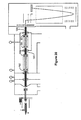
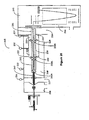
Figure 2A illustrates an electrospray ion source orthogonal pulsing Time-Of-Flight mass analyzer with an ion reflector configured with seven multipole ion guides positioned in series along a common axis, and six differentially pumped vacuum regions. The first, fourth and seventh multipole ion guides extend continuously from a high pressure region to a lower pressure region. The first ion guide extends continuously through two vacuum regions. -
Figure 2B illustrates the configuration of electronic voltage supply units and control modules for the seven multipole ion guide assembly and surrounding electrodes diagrammed inFigure 2a . -
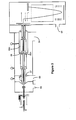
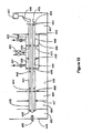
Figure 3 illustrates an electrospray ion source orthogonal pulsing Time-Of-Flight mass analyzer with an ion reflector configured with seven multipole ion guides positioned in series along a common axis, and five differentially pumped vacuum regions. The first, fourth and seventh multipole ion guides extend continuously from a high pressure region to a lower pressure region. -
Figure 4A illustrates an RF multipole ion guide with an ion guide protruding into the collision cell. -
Figure 4B illustrates an RF multipole ion guide with an ion guide protruding into a low pressure region. -
Figure 5 illustrates a configuration similar toFigure 2A using electrostatic lenses. -
Figure 6 illustrates a configuration similar toFigure 2A using smaller multipole ion guides and electrostatic lenses. -
Figure 7A illustrates an alternative Atmospheric Pressure Chemical Ionization Source analyzer configured with a hexapole ion guide at the entrance of the skimmer and at the exit of the collision cell, both which continuously extends between two vacuum regions, and are close-coupled to an quadrupole ion guide assembly with brubaker lenses on either end. -
Figure 7B illustrates the configuration ofFigure 7A using a TOF analyzer. -
Figure 8 illustrates an alternative Atmospheric Pressure Ion Source analyzer useful in understanding the invention configured with a hexapole ion guide which continuously extends between two vacuum regions, close-coupled to an quadrupole ion guide assembly with brubaker lenses on either end. -
Figure 9 illustrates a mass spectrum of a molecular ion and isotopes with m/z near 997, obtained with the configuration inFigure 8 . -
Figure 10 illustrates a set of transmission vs. RF voltage (labeled m/z) at various peak widths for a nearly monoisotopic ion near m/z 922. -
Figure 11 illustrates a set of transmission vs. RF voltage (labeled m/z) at various pressures for a molecular ion and isotopes near m/z 997. -
Figure 12 illustrates an alternative embodiment of an Atmospheric Pressure Ion Source analyzer configured with a hexapole ion guide at the entrance of the skimmer and at the exit of the collision cell, both which continuously extends between two vacuum regions, and the first which is close coupled to a 3mm quadrupole ion guide assembly. -
Figure 13 illustrates a mass spectrum of a molecular ion and isotopes with m/z near 997, obtained with the configuration inFigure 12 . -
Figure 14 illustrates an MS/MS spectrum of a fragments from the molecular ion with m/z near 609, obtained with the configuration inFigure 12 . -
Figure 15 illustrates an MS/MS spectrum of a fragments from the molecular ion with m/z near 609, comparing the configuration inFigure 12 with a conventional collision cell as inFigure 1 . -
Figure 16 illustrates an electrospray ion source orthogonal pulsing Time-Of-Flight mass analyzer with an ion reflector configured with nine multipole ion guides positioned in series along a common axis, and five differentially pumped vacuum regions. The first, and fifth and ninth ion guides extend continuously from a high pressure region to a lower pressure region. The three segments within the collision cell provide additional functionality. -
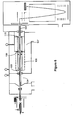
Figure 17 illustrates an Atmospheric Pressure Ionization Source ion source orthogonal pulsing Time-Of-Flight mass analyzer with an ion reflector configured with seven multipole ion guides positioned in series along a common axis and six differentially pumped vacuum regions with a collision cell that is designed to be conductance limiting in a controlled manner. -
Figure 18 illustrates the cross section of one embodiment of such a conductance limiting ion guide inFigure 17 . -
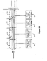
Figure 19 illustrates an electrospray ion source orthogonal pulsing Time-Of-Flight mass analyzer with an ion reflector configured with seven multipole ion guides positioned in series along a common axis, and six differentially pumped vacuum regions. The first, and fifth and seventh ion guides extend continuously from a high pressure region to a lower pressure region. -
Figure 20 illustrates an electrospray ion source orthogonal pulsing Time-Of-Flight mass analyzer with an ion reflector configured with nine multipole ion guides positioned in series along a common axis, and six differentially pumped vacuum regions. The first, fifth and seventh multipole ion guides are of smaller diameter than the rest, and extend continuously from a high pressure region to a lower pressure region. The first ion guide extends continuously through two vacuum regions. -
Figure 21 illustrates a multiple segmented ion guide with the first ion guide consisting of discrete segments, one segment which extends continuously through a vacuum gradient, configured with a MALDI source. -
Figure 22 illustrates a multiple segmented ion guide with the collision cell ion guide consisting of discrete segments, one segment which extends continuously through a vacuum gradient, configured with a MALDI source. -
Figure 23 illustrates two ion guides that extends continuously through five vacuum gradients, configured with a MALDI source. -
Figure 24 illustrates multiple ion guides which are useful for understanding the invention and that extend continuously through five vacuum gradients, one that is configured with two discrete ro values, configured with a MALDI source. -
Figure 25 which is useful for understanding the invention consists of one ion guide of variable ro that extends continuously through two vacuum gradients MALDI source. -
Figure 26 illustrates an electrospray ion source orthogonal pulsing Time-Of-Flight mass analyzer with an ion reflector configured with seven multipole ion guides and two electrostatic lenses, with the seventh ion guide housed in a separate pressurized region. The ion guides are positioned in series along a common axis, and five differentially pumped vacuum regions. The first and seventh multipole ion guides extend continuously from a high pressure region to a lower pressure region. -
Figure 27 illustrates a six segmented multipole arrangement, with the second ion guide in a separate pressurizable region. -
Figures 28 to 33 show further mass analyzers and ion guide arrangements that embody the invention. - An RF multipole ion guide that extends continuously from one vacuum pumping stage into at least one additional vacuum pumping stage configured in a mass analyzer apparatus has been described in
U.S. patent number 5,652,427 . Ion trapping within an RF multipole ion guide coupled with release of at least a portion of the ions trapped within the multipole ion guide followed by pulsing of the released ions into the flight tube of a Time-Of-Flight mass analyzer flight tube is described inU.S. patent number 5,689,111 . The operation of an RF multipole ion guide configured in an API TOF mass analyzer to achieve MS and MS/MSn analytical capability has been described inU.S. Patent Application Serial Number 08/694,542 . The operation of a variety of configurations with multiple ion guides primarily in high pressure regions has been described in patentS/N 09/322,892 U.S. patents 5,652,427 and4,963,736 . Operating an RF multipole ion guide in a high pressure region or a region in which the pressure gradient extends from high to low pressure has been described in patent applicationS/N 09/322,892 - Segmented or non segmented multipole ion guides which extend continuously from one vacuum pumping stage into another in an atmospheric pressure ion source mass spectrometer instrument, can efficiently transport ions over a wide range of background pressures, and can deliver ions from an atmospheric pressure ion source to a mass analyzers including but not limited to TOF, FTMS, quadrupoles, triple quadrupoles, magnetic sector or three dimensional ion traps. Alternatively, assemblies of segmented or non segmented multipole ion guides configured with at least portion of the multiple ion guide assembly positioned in a higher vacuum pressure region can be operated directly as a mass analyzer with MS and MS/MS analytical capability.
- Embodiments of the present invention, described in the following sections, utilize adjacent multipole ion guides that extend continuously throughout various higher and/or lower pressure regions, providing additional mass spectrometer functions and function effectiveness over prior art.
- Single section or segmented multipole ion guide assemblies can be configured such that at least one segment extends from one vacuum pumping stage continuously into at least one adjacent vacuum pumping stage. Multiple ion guides that extend into more than one vacuum stage are configured with relatively small inner diameters (small ro) to minimize the neutral gas conductance from one vacuum stage to the next. Minimizing gas conductance reduces vacuum pumping costs for a given background target pressure.
- In Some embodiments of the invention, individual multipole ion guides are configured as axially aligned assemblies, with one or several ion guide assemblies extending between multiple pressure regions, and with one or several ion guides positioned in a high pressure region, and with one or several ion guides positioned in a low pressure region. This configuration permits the utilization of several distinct physical processes within one ion guide. Each stage has an impact on the analytical performance of the mass spectrometer, and can improve the performance when utilized optimally. For example, in the higher pressure region, the ions experience multiple collisions with the background gas, which reduce the radial and axial kinetic energy of the ion beam. As the gas flows toward lower pressure, a pressure gradient is produced within the ion guide. This provides a changing rate of collisions, which permits the ability to control competing processes, such as energy deposition vs. collisional damping, for example, eventually freezing one or more processes at various positions along the ion guide. Finally, the other section of the same ion guide is positioned in a region where few or no collisions occur, permitting the performance of a function without perturbing the frozen state of the ion.
- In the present techniques,analytical functions such as collision-induced dissociation (CID) that are performed in a pressurized collision cell or region benefit from the use of continuous ion guides extending through various pressure regions. Typically a collision cell is configured with an entrance and exit aperture that serves the dual purpose of differential pumping and electrostatic focussing. As discussed previously, the electrostatic lens tends to cause scattering losses in moderate pressure regions, reducing ion transmission. In the present invention, single section or a segmented multipole ion guide assemblies are configured such that one or more segments extend continuously from the entrance and/or exit of the collision cell, into the lower pressure vacuum regions, enhancing total ion transmission and increasing mass spectrometer functionality.
- Some advantages of embodiments of the invention, as will be discussed below, include: improved RT characteristics of an ion beam transmitted into an RF/DC quadrupole mass filter from a
high pressure 130 Pa-1300 Pa (1-10 torr) region; improved RT characteristics of ion beam transmitted into an RF/DC quadrupole mass filter from a collision cell; enhanced decoupling of multiple functions such as CID and collisional cooling; improved mass to charge selection; and enhanced CID functions such as high efficiency, near single collision CID. - At the same time, many other advantages of multiple ion guides are utilized. For example, an important feature of adjacent ion guides operating in ion trapping mode is that ions can be released from one end of an ion guide assembly or segment simultaneously while ions are entering the opposite end of the ion guide assembly or individual segment. Due to this feature, an RF multipole ion guide receiving a continuous ion beam while operating in trapping mode can selectively release all or a portion of the ions located in the ion guide into another ion guide, ion guide segment or another mass analyzer that performs mass analysis on the released ions. As was described above, an important feature of multipole ion guides is that ions in stable trajectories can be released from one end of an ion guide or ion guide segment operating in single pass or ion trapping mode simultaneously while ions are entering the opposite end of the multipole ion guide or individual segment. Due to this feature, a segmented ion guide receiving a continuous ion beam can selectively release only a portion of the ions located in the ion guide into another multipole ion guide or other mass analyzer that performs mass analysis on the released ions. In this manner ions delivered in a continuous ion beam are not lost in between discrete mass analysis steps.
- Multipole ion guides have been used for a wide range of functions including the transport of ions in vacuum and for use as ion traps, mass to charge filters and as a means to fragment ion species. An RF multipole ion guide comprises a set of parallel electrodes, poles or rods evenly spaced at a common radius around a center point. Sinusoidal voltage RF potentials and +/- DC voltages are applied to the ion guide rods or electrodes during operation. The applied RF and DC potentials are set to allow a stable ion trajectory through the internal volume of the rod length for a selected range of mass to charge (m/z) values. These same RF and DC voltage potentials can be set to cause an unstable ion trajectory for ion mass to charge values that fall outside the operating stability window. An ion with an unstable trajectory will be radially ejected from the ion guide volume by colliding with a rod or pole before the ion traverses the ion guide length.
- Multipole ion guides are typically configured with an even set of poles, 4 poles (quadrupole), 6 poles (hexapole), 8 poles (octapole) and so on. Odd number multipole ion guides have also been described but have not been commonly used in commercial instruments. Quadrupoles, hexapoles and octapoles operating with RF only voltages applied have been configured as multipole ion guides in mass spectrometer instruments. An RF multipole ion guide configured with a higher numbers of poles, operated in RF only mode, can transfer a wider range of ion mass to charge values in a stable trajectory than an RF multipole ion guide configured with a lower number of poles. The multipole ion guides described in the invention can be configured with any number of poles.
- Due to the performance differences in multipole ion guides with different numbers of poles, a suitable choice of ion guide will depend to a large measure on its application. For example, where ion mass to charge selection is desired, higher resolving power can be achieved with quadrupoles when compared to mass to charge selection performance of hexapoles or octapoles.
- Quadrupole ion guides operated as mass analyzers or mass filters have been configured with round rods or with the more ideal hyperbolic rod shape. In an ideal quadrupole ion guide the pole shapes would be hyperbolic but commonly, for ease of manufacture, round rods are used. For a given internal rod to rod spacing (r0), the effective entrance acceptance area through which an ion can successfully enter the multipole ion guide without being rejected or driven radially out of the center volume, increases with an increasing number of poles. Where an assembly of individual multipole ion guides are configured, a mixture of quadrupole and hexapole or octapoles may be preferred for optimal performance. The same RF, auxiliary AC and DC potentials are applied to opposite pole sets for most quadrupole operating modes. Adjacent poles have the same RF frequency and amplitude but a phase difference of 180 degrees. When the offset or common DC potential is subtracted, adjacent poles generally have the same amplitude but opposite polarity DC potentials applied. In addition to the drive RF, single or multiple resonant frequency AC waveform voltages can be applied to the quadrupole rods to achieve ion mass to charge selection and ion fragmentation functions. A common DC offset can be applied to all rods. The primary RF, opposite +/- DC, common DC and resonant frequency AC potentials can be applied simultaneously or individually to the poles of a segmented quadrupole ion guide to achieve a range of analytical functions.
- As discussed in patent
S/N 09/322,892 - Mass to charge selection in higher pressure regions can provide the advantage that ions are slowed in both r and z directions by collisions with the background gas. Ions spending increased time in the multipole ion guide are exposed to an increased number of RF cycles. In this manner higher resolving power can be achieved for shorter multipole ion guide lengths than can be attained using a quadrupole mass analyzer with the more conventional method of operating in low background pressure collision free single pass non trapping mode. Additionally, ions can be slowed as they are delivered from a high pressure region to a low pressure region, and the collisions that result from the pressure gradient can aid the resolving power when operating low pressure mass to charge filters. For example, ions can be trapped in low pressure quadrupoles by cooling in the gaseous pressure gradients established either downstream or upstream or both, at one or both ends, of the quadrupole ion guide. The +/-DC can correspond to the stability tip, or it can be reduced to prevent any scattering losses at the tip, and resonant excitation such as quadrupolar or dipolar excitation can be used to eject ions within the small stability region. In this way higher resolving power can be achieved even with low pressure quadrupoles.
- Multipole ion guide rod assemblies have been described by Thomson et. al. in
U.S. Patent Number 5,847,386 that are configured with segmented, non parallel or conical rods operated in RF only mode, producing an asymmetric electric field in the z or axial direction during operation. This axial electric field can aid in pushing the ions through the length of the ion guide more rapidly than can be achieved with a parallel set of non segmented rods for a given application. Conical or asymmetric rod assemblies can be used in some embodiments of the invention where RF only operation is used for a given multipole ion guide assembly. In an effort to limit the number of embodiments presented, the invention will be described for multipole ion guides configured with parallel rod or electrode ion guide assemblies. Axial fields within a given multipole ion guide assembly are applied as described in some embodiments using RF only entrance and exit pole sections or segments. - The multipole ion guide assemblies can operate individually and jointly in both trapping and non trapping modes with DC acceleration fragmentation and resonant frequency excitation CID fragmentation and mass to charge selection with RF and +/- DC and resonant frequency ejection of unwanted ions. Optimal quadrupole geometries, segmentation, gas pressure and composition, RF and +/- DC amplitudes and secular frequencies applied and the timing of applying RF, +/- DC and auxiliary potentials may not be the same for each analytical function mentioned below and will vary with the mass to charge of an ion of interest. In cases where the ion guides serve as differential pumping tubes, the ion quadrupole geometries are optimized for conductance limit.
- A preferred embodiment of the invention includes a hybrid API source-quadrupole-TOF mass analyzer, comprising: an API source; an assembly of seven quadrupole ion guides with at least one ion guide operated in a lower pressure region for mass to charge selection, and at least one ion guide operated in a higher pressure region for fragmentation; and a Time-of-Flight mass analyzer. A multiple quadrupole ion guide assembly configured according to the present techniques in such a hybrid API source quadrupole TOF mass analyzer allows the conducting of a wide range of MS and MS/MSn analytical functions with high sensitivity, high resolving power and high mass measurement accuracy. Patent Application
S/N 09/322,892 - Another preferred embodiment comprises a multiple RF multipole ion guide assembly, positioned end to end, with the pressure at entrance of ion guide sufficiently high where ion collisions with background gas occurs, permitting effective ion beam cooling, and with at least one ion guide in the center of the assembly being evacuated to low pressure where effectively no ion collisions occur. All of the non-trapping and trapping methods for MS and MS/MSn capability described in Patent Application
S/N 09/322,892 - The second configuration is the assembly of individual quadrupole ion guides that extend either continuously from regions of low pressure to high pressure, or regions high pressure to low pressure, or both, including continuous extensions within pressurized ion guides to evacuated regions, and including regions of pressure gradients within the ion guides which extend between adjacent regions of differential pressure.
- The third configuration described is the assembly of adjacent segmented quadrupoles that contain at least on segment that continuously extends between two regions of differential pressure.
- The fourth configuration described is an ion guide assembly with discretely variable ro that extends continuously through contiguous vacuum regions.
- The embodiments can be operated to perform the API MS mass analysis functions similar to conventional single quadrupole mass analyzers operated in low vacuum pressure. Although the hybrid instrument as described includes a TOF mass analyzer, an FTMS, magnetic sector, three dimensional ion trap or quadrupole mass analyzer can be substituted for the Time-Of-Flight mass analyzer.
- A preferred embodiment of the invention is illustrated in
Figure 2A . Alinear assembly 22 of four independent quadrupole ion guides 23, 24, 25 and 26 and three smaller quadrupoleion guide segments common axis 27 and are configured in a six vacuum pumping stage hybrid API source-multiple quadrupole TOF mass analyzer. (Eachquadrupole ion guide quadrupole ion segments common centerline 27. Each electrode ofion guide 23 has a tapered entrance end contoured to match the angle ofskimmer 10. Thejunctions 42 and 43 are positioned in stages that separate vacuum stages 46, 47 and 48. Ion guide 23 is of appropriate design with sufficient diameter and length to restrict the pumping through thevacuum chamber junctions 42 and 43, for differential pumping inregions Segment 39 ofion guide 24 separates inspace ion guide 23 fromion guide 24 and serves as an ion gate for trapping and release of ions inion guide 23. Similarly thejunctions higher pressure regions 49 within thecollision cell assembly 51 usingion guide 40 and 26 of appropriate diameter and length to restrict the pumping through thevacuum chamber junctions Segment 40 separates inspace ion guide 24 from ion guide 25, and ion guide segment 41 separates ion guide 25 and 26 and serves as an ion gate for trapping and release of ions in ion guide 25.Ion guide section 40 extends continuously through thecell junction 44 into thevacuum chamber region 48, and ion guide 26 extends continuously through thecollision cell junction 45 into thevacuum chamber region 49. The TOF, Time-Of-Flight mass analyzer, configured in sixth vacuum stage 52. Vacuum stages 59, 46, 47,48, 50 and 51 are typically maintained atpressures 67 to 400 Pa (0.5 to 3 torr), 0.013 to 1.3Pa (0.1 to 10 mtorr), 67-670 x 10-4 Pa (0.5-5 x 10⁻⁴ torr), 0.67-670 x 10-3 Pa (0.005-5 x 10⁻³ torr), 130 to 1100 x 10-5 Pa (1 to 8 x 10⁻⁵ torr) and 13 to 670 x 10-7 Pa (0.1 to 5 x 10⁻⁷ torr) respectively. -
Multiple valves vacuum region collision cell 51 can be used to increase or shut off excess gas for various operations. For example, it may be desirable to operate at slightly elevated pressure (e.g. 133 x 10-4Pa (1 x 10⁻⁴ torr))inregion 48 to perform multiple mass to charge selection inion guide 24 using resonant excitation methods with or without trapping, for example in cases where high throughput is required and the product ions are well known. - Although
Figure 2A demonstrates a six pumping stage device with a continuous extension ofion guide 23 throughvacuum chambers junctions 42 and 43, which is appropriate for a particular combination of ion guide diameters, lengths and vacuum pumping speeds, the number of stages as such can vary from one to several depending on the particular combination of rod dimensions and pump speed. - Similarly, although ion guide 26 extends into
collision cell regions 49 andvacuum stage 50 throughjunction 45, any number of vacuum junctions and regions may be used for a particular configuration, from either the entrance or exit of the collision cell. For example,Figure 3 illustrates a representation of the linear ion guide with fivevacuum regions Junction 87 is electrically insulated supporting ion guide 89 which extends the twovacuum regions Junction 88 is an electrical insulator supportingion guide section 88A which extends from insidecollision cell region 88B intovacuum pumping stage 84. - The lengths of each ion guide section may vary. For example the length and the degree to which the ion guide extends into or through various pressure gradients can be selected judiciously on the basis of conductance considerations, desired transit time within a particular pressure region, and desired pressure gradients.
Figure 4a displays a similar configuration as shown inFigure 2 except thation guide 90 inFigure 4a has been extended to protrude deeply intocollision cell 91. Alternatively, as shown inFigure 4b , the configuration can be designed to permition guide 92 to extend more deeply into thelower pressure region 93. - As stated earlier, any number of multipoles, any frequency, with any radial cross section, may be used for this invention, as long as it is suitable for the pumping requirements. In some cases quadrupole rods may be preferable to provide additional functionality is possible such as m/z selection; and the collisional focusing tends to create a narrower beam profile.
-
Electrospray probe 28, illustrated inFigure 2A is configured to direct solution flow rates to probetip 29 ranging from below 25 nl/min to above 1 ml/min. Alternatively, the API MS embodiment illustrated inFigure 2 can be configured with an Atmospheric Pressure Chemical Ionization (APCI) source, an Inductively Coupled Plasma (ICP) source, a Glow Discharge (GD) source, an atmospheric pressure MALDI source or other atmospheric pressure ion source types. API sources may be configured with multiple probes or combinations of different probes in one source. Ion sources that operate in vacuum or partial vacuum including but not limited to chemical Ionization (CI), Electron Ionization (EI), Fast Atom Bombardment (FAB), Flow FAB, Laser Desorption (LD), Matrix Assisted Laser Desorption Ionization (MALDI), Thermospray (TS) and Particle Beam (PB) can also be configured with the hybrid mass analyzer apparatus illustrated inFigure 2 . Sample bearing solutions can be introduced intoES probe 28 using a variety of liquid delivery systems. Liquid delivery systems may include but are not limited to, liquid pumps with or without auto injectors, separation systems such as liquid chromatography or capillary electrophoresis, syringe pumps, pressure vessels, gravity feed vessels or solution reservoirs.ES source 30 is operated by applying potentials tocylindrical electrode 31,endplate electrode 32 andcapillary entrance electrode 33. Counter current dryinggas 34 is directed to flow throughheater 35 and into the ES source chamber throughendplate nosepiece 36. Bore orchannel 58 through dielectriccapillary tube 37 begins atentrance electrode 33 and exits atexit electrode 38. The electrical potential of an ion being swept through dielectriccapillary tube 37 into vacuum may change relative to ground as described inU.S. patent number 4,542,293 . Ions enter or exit the dielectric capillary tube with different potential energy. The use ofdielectric capillary 37 allows different potentials to be applied to the entrance and exit ends of the capillary during operation. This effectively decouples the API source from the vacuum region both physically and electrostatically allowing independent tuning and optimization of both regions. To produce positive ions, negative kilovolt potentials are applied tocylindrical electrode 31,endplate electrode 32 with attachedelectrode nosepiece 36 andcapillary entrance electrode 33.ES probe 28 remains at ground potential during operation. To produce negative ions, the polarity ofelectrodes ES probe 28 remaining at ground potential. Alternatively, if a nozzle or conductive (metal) capillaries are used as orifices into vacuum, kilovolt potentials can be applied toES probe 28 with lower potentials applied tocylindrical electrode 31,endplate electrode 32 andelectrode 33 during operation. With conductive orifices or capillaries, the entrance and exit potentials are equal, so the API source potentials are no longer decoupled from the vacuum region potentials. Heated capillaries can be configured as the orifice into vacuum used with or without counter current drying gas.Capillary exit heater 39 is configured with dielectric capillary 37 to independently heat the exit end ofcapillary 37. - Referring again to
Figure 2 , the general functionality of a preferred embodiment will be described. With the appropriate potentials applied to elements inES source 30, electrosprayed charged droplets are produced from a solution or solutions delivered toES probe tip 29. The charged droplets exitingES probe tip 29 are driven against the counter current dryinggas 34 by the electric fields formed by the relative potentials applied toES probe 28 andES chamber electrodes nebulization gas flow 57 can be applied through a second layer tube surrounding the sample introduction first layer tube to assist the electrospray process in the formation of charged liquid droplets. As the droplets evaporate, ions are formed and a portion of these ions are swept into vacuum throughcapillary bore 58.Vacuum partition 60 includes a vacuum seal withdielectric capillary 37. If a heated capillary is configured withheater 39 as an orifice into vacuum with or without counter current drying gas, charged droplet evaporation and the production of ions can occur in capillary bore 58 as charged droplets traverse the length ofcapillary 37 towards firstvacuum pumping stage 59. - The neutral background gas forms a supersonic jet as it expands into vacuum from
capillary bore 38 and sweeps the entrained ions along through multiple collisions during the expansion. A portion of the ions enteringfirst stage vacuum 59 are directed through theskimmer orifice 60 and intosecond vacuum stage 46. Referring tofigures 2A andB , ions enteringsecond vacuum stage 46 throughskimmer orifice 60 enter segmented quadrupole ion guide assembly 62 (ion guide 23) where they are trapped radially by the electric fields applied to the quadrupole rods. The locally higher pressure in theentrance region 66quadrupole ion guide 23 damps the ion radial motion as they pass through the quadrupole RF fringing fields. The collisional damping of ion motion in this locallyhigher pressure region 66 results in a high capture efficiency for ions enteringquadrupole assembly 62. Ion m/z values that fall within the operating stability window will remain radially confined within the internal volume described by the rods ofquadrupole assembly 62. The trajectories of ions that fall within the stability window defined by the potentials applied to the rods ofion guide 23 will damp towardscenterline 27 while traversing the length ofion guide 23. - In this configuration, the ions are transported through
vacuum regions junctions 42 and 43. Each rod ofion guide vacuum partitions vacuum regions vacuum region 48, the pressure is sufficiently low that collisions essentially stop, and the ions no longer experience velocity changing due to collisions. Ion trajectories that have been damped tocenterline 27 are efficiently transferred intosegment 39 ofquadrupole assembly 63 when the appropriate relative bias voltages are applied betweenion guide 23 andion guide 24 withRF section 39. - As described earlier, ions experience several collisions with the neutral background gas molecules as they traverse the volume defined by
quadrupole ion guide 23 invacuum stage 46, and the number of collisions decreases continuously throughvacuum stage 47 until eventually very few collisions are experienced in the lowpressure vacuum stage 48. In continuous beam mode, ions are transported throughion guide sections 40 and 41, with the ion guides adjusted to allow maximum transmission in RF-only mode. In this mode, the ion beam is passed through collision cell ion guide 25, operating in RF-only mode, at low collision energy, i.e. the DC offset between ion guides 23, 24, and 25 are similar enough to prevent acceleration and fragmentation of the ion beam with background collision gas incollision cell 51. The ion beam is efficiently transported throughion guide assembly Collision cell 51 may be sufficiently pressurized to permit ion beam translational energy cooling through ion guides 25 and 26, providing a phase space profile suitable for the TOF entrance and pulsingoptics 56. - In one embodiment of MS/MS,
ion guide 24 is operated in mass selection mode, for example as an RF/DC resolving quadrupole mass filter, and in this configuration a particular m/z value (or set of values) is selected from the well-defined ion beam. Due to the design ofion guide 23 inregion ion guide 24 during mass-to-charge selection operation. The selected ion can be fragmented the with conventional methods such axial acceleration CID, whereby the ions are accelerated into a high pressure region, typically as they are transported throughcollision cell 51 by applying an acceleration potential between either ion guides 23, 24 and 40 or 40 and 25. Alternatively the ions can be fragmented using a low acceleration voltage by auxiliary excitation CID with the auxiliary frequency tuned to the mass of the precursor ion applied to the rods of ion guide 25. The resulting product ions are then further transported through ion guide 26 that extends frominside collision cell 51 intovacuum pumping stage 50. Ion guide 26 is configured with an appropriate dimension to provide a sufficient conductance limit acrossjunction 45, with the appropriate choice of pumping. As the ions exitcollision cell 51, they traverse a smoothly varying pressure gradient within ion guide 26 that initially provides damping of ion translation energies. Ions exiting ion guide 26 experience minimum collisions with background gas, preserving the low ion beam energy spread required for precise focusing through lens 68 into time offlight pulsing region 56. - Ions traversing the
pulsing region 56 are either pulsed into TOFflight drift region 73 or continue throughpulsing region 56 passing throughorifice 74 inlens 75. By applying appropriate voltages tolens 75,electron multiplier detector 76,conversion dynode 77 and Faraday cup 78, ions passing throughorifice 74 can be directed to impact onconversion dynode 77 or be collected on Faraday cup 78. Secondary electrons or photons released fromconversion dynode 77 after an ion impact are detected byelectron multiplier 76. TheTOF analyzer 71 is described in detail in patent applicationS/N 09/322,892 - In the embodiment of the hybrid TOF shown in
Figure 2 , full fragment ion spectra are recorded in the TOF analyzer without scanning, resulting in higher sensitivity and resolving power than can be achieved in triple quadrupole operation. The hybrid TOF MS as illustrated inFigure 2 can be operated in such a way as to provide full triple quadrupole functionality, with the TOF mass spectra acquired replacing the third quadrupole single mass selection and mass scan analytical functions. Provided that the ion population delivered to pulsingregion 56 is properly focused with a minimum off axis component of energy, a range of analytical functions can be achieved upstream of pulsingregion 56 without modifying optimal tuning of TOFmass analyzer 71. - To generate a non-continuous beam for trapping in
ion guide ion guide segments 5,689,111 . It is also possible to operate ion guides 23 and 26 as resolving mass filters. In this case the hybrid TOF illustrated inFigure 2 can contain a full triple quadrupole coupled to aTOF mass analyzer 71.Detector 76 can be used for direct triple quadrupole analysis. - Adjacent ion guides, particularly of similar diameter and frequency, require additional considerations to minimize capacitive coupling and fringe field effects. Capacitive coupling induces voltage pickup on the neighboring rods, and can reduce the overall response time of the ion guide elements. As described in patent application
S/N 09/322,892 segments Figure 2b ,power supply modules ion guide assemblies ion guide segments Figure 2A serve to decouple quadrupole ion guides 23, 24, 25 and 26 both electrically and functionally, as well as provide an element to apply high and low voltages for ion trapping, with gated release as will be discussed later. These segments may be capacitively coupled to the neighboring ion guides as shown inFigure 2B ; alternatively some or all can be driven by separate supplies. - As described in patent application
S/N 09/322,892 power supply modules ion guide assembly 22 it experiences a single oscillatory field (of different amplitudes), reducing the likelihood of transmission losses due to fringe field effects at the ends of the segments. -
Vandermay in US Patent 6340814 B1 describes an alternative approach to removing the problem of capacitive coupling of adjacent quadrupoles whereby the capacitance between adjacent but opposite poles is neutralized. Whitehouse, et. al. in Patent S/N 09/322,892 describes methods for reduction of deleterious effects due to capacitative coupling. - Alternatively, electrostatic lenses can serve to decouple adjacent segments physically and electronically, for example from any rapidly changing RF and +/- DC potentials applied to the rods. They can also be used as differential pumping apertures, and additionally they can enable rapid switching of voltages between ion guides. An alternative embodiment of the invention consisting of three electrostatic ion lenses is illustrated in
Figure 5 which displays an electrospray source-orthogonal pulsing Time-Of-Flight mass analyzer with an ion reflector, and six differentially pumped vacuum regions, and is configured with six multipole ion guides 94, 95, 96, 97, 98 and 99 positioned in series alongcommon axis 100. Ion guides 94 and 95 are separated byelectrostatic lens 101, and likewiseelectrostatic lenses Lenses Figure 6 displays a similar arrangement as shown infigure 5 but ion guides 104 and 105 are smaller diameter hexapole ion guides aligned with larger diameter quadrupoleion guide assemblies Lenses ion guide assemblies - Mass to charge selection resolving power and transmission efficiency in an RF/DC quadrupole can be improved by using a continuous hexapole ion guide extended between two vacuum stages.
Figure 7A illustrates an embodiment of the invention, using a configuration of an ion guide assembly containing individualion guide assemblies DC quadrupole assembly 115 and an electronmultiplier detector assembly 116.Electrostatic lens 117 serves as a differential pumping aperture for thecollision cell 113.Ion guide assembly 112 can be operated as an RF/DC resolving quadrupole. Ions are generated using APCI source118 and sampled through the capillary 119 andskimmer 120 as described above. Ion guides 111 and 114 are configured as small diameter hexapoles with 1 mm rods, approximately 7 cm in length.Ion guide 111 extends fromskimmer orifice region 121 and extends throughvacuum junction 122 which separates thehigher pressure region 123 of ~1.3Pa (~10mTorr) from thelower pressure region 124 of 400e-5 Pa (~3e-5 torr).Ion guide 111 may have a tapered entrance to match the internal angle ofskimmer 120.Ion guide 114 extends into thecollision cell assembly 126 with internal pressure region 125 maintained at elevated vacuum pressures up to 2.7 Pa (20 mTorr). - As will be illustrated below, the transmission of the RF/DC resolving quadrupole is improved at both unit resolution and at moderately high resolving power. The transmission is also improved somewhat at elevated pressures. This is the case for both ion beam entering a first resolving
quadrupole 112, and a second resolvingquadrupole 115 placed down stream ofcollision cell 126 andion guide 114. AlthoughFigure 7A illustrates a triple quadrupole arrangement,assemblies TOF analyzer 127, as is shown inFigure 7B , here configured with an atmosphericpressure MALDI source 128. -
Figure 8 illustrates a configuration usinghexapole ion guide 129 to transport ions betweenvacuum regions capillary 133 and expanded with neutrals through a free jet expansion invacuum region 134. lonspass through a 1.2 mm orifice diameter 125 inskimmer 135. Ions are then transported throughvacuum region 130, maintained at a pressure of approximately 5mTorr throughhexapole ion guide 129 operating at 2.5 MHz throughion guide 129 and exit in low-pressure region 131 (400 x 10-5 Pa (3 x 10⁻⁵ torr)). There they are transferred intoBrubaker lens element 132, and mass to charge selected by the RF/DC resolving quadrupolemass filter 133 operating at 880 kHz (with r0 ~9 mm, 1=20cm). No electrostatic lenses separate the ion guides even though the ion guides operate at different frequencies. The ion beam is mass analyzed by scanningion guide 133, transmitted throughsegment 134 andlenses 135 and 136, where the ions are detected withelectron multiplier assembly 137. - This advantage is demonstrated in
Figure 9 , using the configuration inFigure 8 . Here curve 106 illustrates excellent resolving power, shown for the molecular ion hexatyrosine, withmass isotopes z z 997. A set of transmission curves 110 of an ion beam consisting of ions with m/z 922 is shown inFigure 10 for various RF/DC ratios applied to the RF/DC resolving quadrupolemass filter 133. Peak widths are increased by increasing the RF to DC ratio. For example, curves 111, 112, 113, 114 and 115 correspond to peak widths of 0.37, 0.58, 0.8 and 2.4 and 9 Da. Only a 25% loss in sensitivity is observed at standard operating conditions (typically 0.8 FWHM, curve 114), above the maximum transmission achievable,curve 115. Typically losses near x2 to x4 are observed with a similar configuration and electrostatic lenses. These data are acquired at a background pressure of 470e- 5 Pa (3.5 e-5 torr), - In addition to improved transmission at lower pressure, the configuration in
Figure 8 also yields improved transmission at higher pressure. Referring toFigure 11 , a set of massspectral curves 116 is shown for a variety of background gas pressures. As discussed above, ions that undergo collisions with the background gas suffer changes in position and velocity that repel them from the RF and +/-DC field. Intensities are shown for a number of pressures inFigure 11 .Curves quadrupole ion guide 129 inFigure 8 . Even though the ions suffer the same number of collisions as they move through the resolving quadrupole, a smaller fraction of them change the phase space significant enough to scatter them out of the stability region. -
Figure 12 illustrates an embodiment of the invention that is designed to study the ion beam phase space obtained by utilizing hexapole ion guide 130A to transport fragment ions from thecollision cell 132A into the RF/DC resolving quadrupole 131A. In this case,ion guide 132A is pressurized to 130- 670 x 10- 3 Pa (1-5 x 10⁻³ torr) and the RF/DC resolving quadrupole 131A operates at 470e-5Pa (3.5e- 5 torr). Here, hexatyrosine or reserpine molecular ions are mass to charge selected using aquadrupole ion guide 133A at low resolving power (R∼200). First attention is paid to the analysis of precursor ions that are transported but not fragmented bycollision cell 132A. Precursor ions are transported through the pressurized ion guide at 0.13 Pa (1 x 10⁻³ torr) via a weak acceleration field, using a small relative DC offset between ion guides 133A and 134A.Ion guide 134A operates at 880 kHz and a voltage is applied to yield q=0.35 for the selected ion. Precursor ions are transmitted through ahexapole ion guide 130A, where they are injected intoBrubaker lens element 135A and resolved by the RF plus +/-DC quadrupolemass filter 131A operating at 880 kHz (with ro ∼9 mm, l=20cm). The ions are transported through theBrubaker exit lens 136A and detected by theelectron multiplier assembly 137. No electrostatic lenses separate the ion guides 134A, 130A and 135A even though they operate at different frequencies.Figure 13 ,curve 138 illustrates a spectrum of hexatyrosine with a resolving power of 3000 and a sensitivity loss of x8 over unit resolution. This result is very similar to that described above inFigure 9 . - Next attention is paid to the analysis of fragment ions created by CID of the precursor ion.
Figure 14 illustrates aCID spectrum 139 of protonated reserpine, m/z 609,and using the configuration inFigure 12 . Here ions are accelerated into thecollision cell 132A using 50 eV lab frame collision energy, by adjusting the appropriate upstream ion guide DC offsets. The mid-mass capture efficiency is estimated to be at least 4x larger than a lens alone, and 2x better than a brubaker lens in series with an electrostatic lens. Although the efficiency is better for the embodiment herein, we note that the fragmentation patterns are identical, as shown inFigure 15 , wherecurves collision cell 132A in place of the ion guide130A. - As discussed, an ion beam that is transported through continuous ion guides 129A and 130A from a moderate pressure region of 0.13-1.3 Pa (1-10 mTorr), into low pressure region of 13-670e-5 Pa (0.1-5e-5 torr) results in improved transmission characteristics of the RFIDC quadrupole mass filter. The improvements are believed to be due to an enhanced ion beam quality whereby ions are collisional damped in a high-pressure region and smoothly transferred to a low-pressure region with minimal perturbation. As discussed earlier, collisions with the background gas serve to radially and axially reduce the ion kinetic energy spread. This produces a well-defined, narrow ion beam, with phase space coordinates suitable for transmission into an RF plus +/-DC quadrupole operating near the stability tip. As described by Dawson, losses in transmission at moderately high resolving power tend to be caused by ions with unsuitable phase space coordinates. Therefore, when acceptable phase space can be maintained, the resolution-transmission characteristics are improved.
- Single quadrupole M and MS/MSn TOF operating sequences are described in
U.S. patent application Serial Number 08/694,542 . - Analytical MS and MS/MSn TOF operating sequences employing multiple quadrupoles operating in ion mass to charge selection an ion fragmentation modes are described in patent application
S/N 09/322,892 - The hybrid segmented ion guide TOF embodiment illustrated in
Figure 2 can be configured to achieve all triple quadrupole and ion trap MS/MSn functions using a number of different ion mass to charge selection and ion fragmentation techniques, and combinations of DC acceleration and resonant frequency excitation CID ion fragmentation operation not conducted in either triple quadrupoles or an ion traps. Several combinations of m/z selection and ion fragmentation and mass analysis can be performed sequentially or simultaneously using the embodiment illustrated inFigure 2 . Specific examples of segmented ion guide operating modes will be described below as a means to achieve MS, MS/MS and MS/MSn analytical· functions with and without ion trapping. - Referring again to
Figure 2 , the arrangement offers the advantage of decoupling the CID ion guide 25 function from the ion transport function in ion guide 26. For many analytical applications, CID can occur in ion guide 25 either via axial or radical acceleration methods. The ions then undergo a continuing number of low energy collisions as they are transported through segment 41 and the higher pressure portion of ion guide 26. This provides the reduction in the radial components of velocity, whereby a minimum off-axis component of energy is required to properly resolve ions inTOF analyzer 71. The ions are then smoothly transported into the lower pressure portion of ion guide 26 with minimal perturbation to the beam quality prior to extraction into theTOF analyzer 71. Furthermore, the advantages of inventions from theU.S. Patent Number 5,689,111 can be preserved, where the ions are best focused through lens 68 in a low pressure region. - The present arrangements provide high transmission of ion transport through the multiple segments of the ion guides. Ions can be moved back and forth, enabling multiple functionality, with little transmission loss. Ions can be moved efficiently from one segment or quadrupole assembly to an adjacent segment or quadrupole assembly in blocks. All ions trapped in one segment or quadrupole are transferred to the next sequential segment or quadrupole ion guide assembly before accepting a new population of ions from the previous segment or quadrupole assembly. Each segment or quadrupole assembly can independently perform single or multiple m/z selection, and /or DC acceleration CID as ions are transferred between assemblies, and/or resonant frequency excitation CID within assemblies.
- Trapping functions can be performed by raising the DC offset potentials of
ion guide elements Figure 2 to generate a repulsive field relative to the kinetic energy and polarity of the ions located in each respective upstream ion guide. Trapping with DC offset potentials applied to the poles ofsegments - Referring to
Figures 2A and2B , theelectrospray ion source 30 delivers a continuous ion beam into vacuum. By trapping and release of ions inmultiple quadrupole assembly Figure 2B ), a continuous ion beam can be efficiently converted into a pulsed ion beam, with very high duty cycle as is described inU.S. patent 5,689,111 . Multiple quadrupole assemblies 62-65 can be operated in non trapping or trapping mode where individual quadrupoles or segments of segmented quadrupoles are selectably operated in trapping or non trapping modes. For example, ions are trapped inquadrupole 24 by raising the DC offset potential applied to the rods ofsegments segments quadrupole ion guide 24. - Synchronous trapping and release of ions can be performed in several ion guides simultaneously. For example, ions can be trapped in
ion guide 23 while mass spectrometer functions are performed in ion guide 25, and ions can be released from both ion guides 23 and 25 simultaneously, when the DC offset potentials applied to poles of segment 41 are decreased to release ions into ion guide 26. Additionally, ions can be stored inion guide 23 while an ion packet is transported through ion guides 24, 25 and 26, and reverse-accelerated back into ion guide 25, for example. The three smallerion guide segments - Single or multiple ranges of ion mass to charge selection can be performed as described in patent application
S/N 09/322,892 -
- 1. RF and +/- DC near the apex of the first stability region;
- 2. High mass rejection using high-q with RF-only or with RF and δ +/- DC;
- 3. Low mass rejection using low- q with RF-only or with RF and δ+/- DC;
- 4. Resonant frequency rejection of one or more ranges of ions;
- 5. RF, RF and δ+/-DC in combination with resonant frequency ejection, scanned or static
- Dipolar and/or quadrupolar resonant excitation can be performed using fundamental or higher order modes of excitation, in combination or alone, and dipolar excitation can be performed on one pole pair or both. Adjusting the phase between the dipolar frequency applied to the two pole pairs permits control of the ion trajectory within the quadrupole. For example, ions can be rotated through the quadrupole by applying 90° phase shift between dipolar frequencies on the two pole pairs.
- Each mass to charge selection technique list above can be applied individually or in combination in the hybrid quadrupole TOF illustrated in
Figure 2 . Various approaches can be taken to achieve ion mass to charge selection inion guide 24. Low amplitude RF plus +/- DC applied toion guide 24 yields a large range of transmitted ions which can be further reduced using a mixture of resonant frequency waveforms. Alternatively, at low pressure, RF plus +/- DC near the apex of the first stability region can be applied, with or without additional resonant. - An approach suitable for trapped ions in two dimensional ion traps is described by
Wells et. al. in U.S. Patent Number 5,521,380 for mass to charge selection in three dimensional quadrupole ion traps. The frequency and amplitude composition of the applied resonant frequency waveform can be made of a number of subranges of frequencies. The ions are drawn into resonance within the subrange by sweeping the RF amplitude frompower supply 80 applied toion guide 24. This approach minimizes the number secular frequency components required to eject non selected ion m/z values and minimizes selected ion losses from off resonant frequency excitation during single or multiple ion mass to charge selection. Additionally, low masses can be ejected at the high q cutoff point near q=0.9 and high mass ions can be ejected near the low q∼0 point. - The above approaches are expected to be more efficient in lower pressure regions if a low ion axial velocity can be maintained. The approaches discussed above were specifically applied to
ion guide 24, but can as well be applied to ion guides 23, 25 and 26. Ion guide 25 is positioned in a higher pressure vacuum region, and therefore RF plus +/-DC at the apex is likely unsuitable. - An important aspect of the embodiment is that ion guides 23 and 26 are both positioned across pressure gradients. Typically, lower amplitude excitation is required in a low pressure region, and lower amplitude yields improved selectivity. Collisional cooling, which occurs in the high pressure portion of the ion guide, provides axial and radial velocity reduction; meanwhile resonant excitation and ion ejection, are applied in the lower pressure region using reduced amplitude than is required in a high pressure region. In this way, the amplitude can be set to provide improved selectivity only within the low pressure portion of the
ion guide 23 or 26. - Preventing unwanted ion m/z values from entering
TOF drift region 73 allows more efficient detector response for those ion m/z values of interest, minimizing charge depletion. Radially ejecting undesired m/z value ions from the multipole ion guide prior to TOF pulsing to limit the ion population pulsed into flighttube drift region 73 to only those m/z values of analytical interest for a given application, helps to improve the TOF sensitivity, consistency in detector response and improves detector life. Referring again toFigure 2a ,ion guide 24 is a preferable notch filter relative to a higher pressure ion guide, since notch filter resolving power is better when using low pressure, due to lower required ejection amplitudes. - Low pressure RF plus +/-DC can be used on
ion guide 24 in a low pressure region, efficiently passing a small range of ions according to the applied resolving power. Low pressure multi-frequency auxiliary excitation can also be applied toion guide 24. This technique can permit several ranges of m/z to be transmitted simultaneously. - Ion m/z fragmentation as described in patent application
S/N 09/322,892 several segments S/N 09/322,892 - The following includes this list and extends it in part due to the extended capabilities of the present techniques within pressure gradients or in low or high pressure ion guides:
- 1. Axial DC ion acceleration in pressurized ion guide;
- 2. Axial DC ion acceleration in pressurized ion guide within pressure gradients or in low pressure ion guides;
- 3. Resonant excitation/ radial acceleration of single or multiple ions, using dipolar or quadrupolar excitation, or some combination of dipolar and quadrupolar excitation, with dipolar used on one or both pole pairs in pressurized ion guide;
- 4. Resonant excitation/ radial acceleration of single or multiple ions, using dipolar or quadrupolar excitation, or some combination of dipolar and quadrupolar excitation, with dipolar used on one or both pole pairs within pressure gradients or in low pressure ion guides;
- 5. Non-resonant AC ion acceleration;
- 6. Up-front capillary-skimmer CID;
- 7. High energy CID;
- 8. Boundary-activated dissociation;
- 9. A combination of boundary activated dissociation, axial DC acceleration and resonant excitation/radial acceleration;
- 10. Radial or DC acceleration along the z- axis in fringe fields;
- 11. Radial or DC acceleration along the r-axis in fringe fields;
- 12. Overfilling of quadrupoles during ion trapping until CID fragmentation occurs;
- 13. Fragmentation via ion-molecule reactions;
- 14. Fragmentation via ion-ion reactions;
- 15. Fragmentation via electron capture;
- 16. Fragmentation via photodissociation.
- Each of these CID fragmentation techniques can be used individually or in combination in with the
multiple quadrupole assembly - The present techniques provide the ability to perform improved and alternative CID functions in the pressure gradients. One aspect of the embodiment in
Figure 2 , whereby ion guide 26 extends between apressurized collision cell 51 and alow pressure region 50 throughvacuum junction 45, is the ability to perform CID in the ion guide 26. This provides an alternative pressure regime that contributes to controlling the fragmentation pathway. Typically, when fragment ions are generated in ion guide 25, either by axial or radial acceleration techniques in thepressurized region 51, they are rapidly cooled, depending on the collision frequency. Because the fragmentation pathway depends on the rate of cooling, the fragmentation pathway can be controlled to some degree by controlling the rate of change of the collision frequency along the ion guide. In this way, axial or radial CID in ion guide 26 will give a different set of fragmentation patterns than ion guide 25, providing additional information not otherwise available. - Ion guide 26 extends between a
pressurized collision cell 51 and alow pressure region 50 throughvacuum junction 45. When fragment ions are generated in ion guide 25, either by axial or radial acceleration techniques in thepressurized region 51, they can then be transported through ion guide 26 at low energies prior to entering thelow pressure region 50. As the ions exit thecollision cell 51, they traverse a smoothly varying pressure gradient within an RF ion guide, whereby eventually the phase space of the ion beam freezes, and the high quality ion beam is preserved for exact focusing into theTOF 71. As stated earlier, an additional advantage of the present arrangements is that the trap-pulse function described in patent 5,689,111 is decoupled from the higherpressure CID region 51. Here, trap-pulse ion release takes place in alow pressure region 49, permitting few losses due to scattering collisions, and a better defined focal point of the of the ion packet released into theTOF 71. - As is described in
U.S. patent application 08/694,542 higher energy CID fragmentation can be achieved by accelerating ions back into quadrupole ion guide 26 a portion of which is located in the low pressure region of fifthvacuum pumping stage 50. Ions gated into the gap betweenlenses 68 and 69 are raised in potential by rapidly increasing the voltage applied tolenses 68 and 69. The potential applied to lens 68 is then decreased to accelerate ions back into multiple quadrupole ion guide 26. The reverse direction DC accelerated ions impact the background gas in ion guides 26, 41 and 25. In a similar manner,quadrupole ion guide ion guide 23 in a repetitive manner to rapidly increase the internal energy of an ion population. - Continuous flow methods have the potential advantage of speed, no duty cycle losses during fill and isolation steps, no requirement for synchronizing in the overall timing of pulse-trap, and no ion guide state change during acquisition.
- 1. Axial CID in ion guide 25 with simultaneous with radial excitation in ion guide 25 or 26, plus rapid background subtraction, plus on-the-fly or post-acquisition processing
- 2. Axial CID in ion guide 25 with simultaneous with radial-ejection filtering, followed by CID (radial or axial) in ion guide 25 or 26
- Continuous beam MS/MSn analytical functions can be run using a segmented ion guide operating at high pressure with a non-continuous primary ion beam as described in
US provisional patent S/N 09/322,892 - In one approach, background subtraction methods can be used to obtain MS/MSn spectra with a continuous primary ion beam. Some of these techniques were described in
U.S. patent application number 08/694,542 and by Cousins et. al. (RCM in press), where the m/z selection does not take place prior to ion fragmentation. Instead two spectra are acquired sequentially, the first with a combination of parent or fragment ions and the second with the next generation fragment ions. The first acquired TOF mass spectrum is subtracted from the second to give a spectrum containing peaks of just the MS/MSn fragment ions. Referring again toFigure 2 , axial DC acceleration is applied to ions entering ion guide 25 inpressurized assembly 51 by adjusting the relative DC voltages ofion guide elements - Referring again to
Figure 2 , it is also possible to perform some or all of the above MS/MSn functions in ion guide 26, of which a portion extends into thecollision cell assembly 51 and a portion is positioned in a lowpressure vacuum stage 50. The relative DC offsets between ion guides 23, 39, 24, 40, 25, 41 and 26 can be adjusted to provide DC acceleration and fragmentation across any of the junctions. In the case where fragmentation is desired in a lower pressure region or a pressure gradient, acceleration can take place into ion guide 26. The positioning of ion guide 26 with respect to thejunction 45 can be optimized to permit optimum pressure conditions. Similarly, resonant excitation can be applied toion guide - A second approach using on-the-fly mass-to-charge selection of the fragment ion in the low pressure ion guide can be performed using a combination of resonant excitation and RF/DC techniques. As above, fragments can be generated in ion - guide 25 or 26 by axial or radial acceleration. Moderate or large amplitude resonant excitation and wideband RF/DC can be applied to ion guides 25 or 26 to eject all ions but one or several m/z ranges, transmitting one or more fragment ions. A lower amplitude excitation source can be tuned to the m/z of the MS2 fragment, which can be applied to the same ion guide 25 or 26 to generate the MS3 fragments. Alternatively, the MS2 fragmentation and isolation stages can be performed in ion guide 25 and MS3 fragmentation step in ion guide 26, or isolation and further fragmentation can be applied to ion guide 26. An advantage of this last possibility within the embodiment of
Figure 2 is that the selectivity and power requirements for isolation in ion guide 26 may be optimized based on the location ofjunction 45 and the pressure gradients within ion guide 26. - As stated earlier, an advantage to resonant excitation waveforms used in the above embodiment is that they can transmit multiple m/z ranges simultaneously. It is possible to utilize this capability for higher throughput, for example in cases where the fragmentation spectra are known but quantitation is desired. This can be powerful when coupled with a high resolving power/high
mass accuracy TOF 71 that yields a high degree of specificity with a high duty cycle. - An alternative approach to ion isolation and subsequent fragmentation MS/MS3 is illustrated in
Figure 6 . In the embodiment inFigure 16 , ions are generated by an atmospheric pressure MALDI source, are transported through the sampling region intoion guide 143, and mass to charge selected in the low-pressure ion guide 144. Ions are then accelerated into ion guide 145A or 145B by applying the appropriate DC offsets. Incollision cell assembly 148, three ion guides 145B, 146 and 147 are configured to sequentially induce fragmentation, m/z isolation and subsequent fragmentation. The ion guides can be operated at the same voltage and frequency or different voltages and frequencies, and can be driven by separate RF supplies. -
Ion guide segment 146 via a mixture of resonant excitation and RF plus +/- DC. Subsequent stage fragmentation is performed in ion guide 147. The lengths of each ion guide can be chosen to select the desired transit time through each ion guide. Five ion guides can be used for MS5. An advantage of this approach is that each stage can be optimized separately for frequency and transit time, in order to optimize the overall MSn efficiency. - As stated in a previous section, trapping in a two dimensional ion guide permits the ion to have more time in the excitation fields, providing the opportunity to perform functions that may not be possible in a single mass continuous beam. For example, isolation techniques which require varying the RF voltage (thereby varying q) require more time than is often available during the ion transit through an ion guide, particularly in lower pressures. For example, an approach suitable for trapped ions which combines ramping the RF with a small range of excitation frequencies is described by
Wells et. al. in U.S. Patent Number 5,521,380 . Ion trapping also permits clear definitions of timing, and clear definitions of ion beam composition, making it possible to synchronize multiple events. Some of the methods which can be used in conjunction with ion trapping are listed below. Some of these techniques are described inUS patent application S/N 09/322,892 - Referring again to
Figure 2 , trapping voltages can be applied tosegments - MS/MS can be performed using axial CID in ion guide 25 followed by the subsequent functions for MSn:
- 1. Multiple-stage/reverse-extraction and acceleration
- 2. Trap, isolate and radially excite in ion guide 25
- 3. Trap, isolate, radially excite in ion guide 26
- 4. Trap, isolate in ion guide 25 (RF/DC or radial methods) and axially activate in ion guide 26
- 5. Trap, isolate in ion guide 25 and radially excite in ion guide 26
- 6. Trap, isolate in ion guide 26 (using RF/DC or radial methods) and radially excite into ion guide 26
- 7. Trap, isolate in ion guide 26 using RF/DC or radial isolation; accelerate back into ion guide 25
- Referring again to
Figure 2 , MS/MS can be performed using radial CID in ion guide 25 followed by the subsequent functions for MSn: - 1. Trap, isolate and radially excite in ion guide 25
- 2. Trap, isolate, radially excite in ion guide 26
- 3. Trap, isolate in ion guide 25 (RF/DC or radial methods) and axially activate in ion guide 26
- 4. Trap, isolate in ion guide 25 and radially excite in ion guide 26
- 5. Trap, isolate in ion guide 26 (using RF/DC or radial methods) and radially excite into ion guide 26
- 6. Trap, isolate in ion guide 26 using RF/DC or radial isolation; accelerate back into ion guide 25
- Synchronized trapping and release in
ion guide 23 can take place while these events are occurring. - MS/MSn analytical functions can be run using a segmented ion guide operating at high pressure with a non-continuous primary ion beam as described in
US provisional patent S/N 09/322,892 multiple quadrupole assembly 22 and TOFmass analyzer 71 to conduct MS/MSn analysis with a non continuous primary ion beam in alternating pressure regions. The addition of multiple segments and additional quadrupole assemblies configured in higher and lower background pressure region allows operational and analytical variations not possible when conducting MS/MSn mass analysis sequences with a single segment or with a higher pressure analyzer region. - Referring again to
Figure 2A , in one embodiment of MS/MS2, ions are accelerated into the pressurized ion guide 25 withion guide voltage 40 held attractive, and they are trapped at the exit by applying repulsive voltages to ion guide 41. After some fill time Δt1 the voltage onion guide 40 is raised to trap the ions at the entrance. Simultaneously,ion guide 39 can be held repulsive to trap ions inion guide 23. M/z selection is performed over time Δt2 by one of the above-mentioned methods, for example according to the method described byWells et. al. in U.S. Patent Number 5,521,380 where a range of resonant frequencies is applied. As mentioned above, some combination of dipolar and quadrupolar excitation may be used, and the fundamental and/or higher order modes of excitation may be used. At time Δt3 an additional excitation source is applied such as resonant excitation, and finally at time Δt4 ions are released to the ion guide 26 by applying an attractive voltage to ion guide 41. Simultaneously,ion guide 23 releases a packet of trapped ions for mass selection inion guide 24. Ion guide 26 is now triggered to perform high repetition rate trap-pulse into theTOF analyzer 71 according toU.S. Patent Number 5,689,111 . - In another embodiment of MS/MS2, referring again to
Figure 2a , ion trapping in combination with a method of reverse extraction and acceleration, can be used. At t=0, a pulsed packet of ions is mass selected byion guide 24 in a low pressure region, while the remaining ions are stored in theion guide 23 by applying appropriate voltage toion guide 39. Ion guide 41 is simultaneously raised repulsive. The packet of m/z-selected ions is fragmented inion guide 23 through DC (or radial) acceleration using the appropriate DC offset on the ion guides 23, 39, 24, and 25. After a small time Δt1, the voltage onion guide 40 is raised repulsive. The ions are given another small time Δt2 to cool and equilibrate with the background gas, at which point they are reverse-extracted into. After time Δt3 theion guide voltage 40 is lowered, the voltage onion guide 24 is set to RF-only at q=0.7, for example, whileion guide 39 is raised repulsive. The ions are released and trapped in lowpressure ion guide 24, which benefits from weak leaks that surround it due to pressure gradients. The +/-DC is raised to provide a window of m/z transmission, which is further reduced by applying an additional resonant waveform to eject the remainder of unwanted ions. This waveform may simply be one additional excitation frequency. After some small time Δt4 ions are re-accelerated into the collision cell region for further fragmentation. After time Δt5 the trap-pulse sequence is triggered for ions to be passed through to ion guide 26 for pulsing into theTOF analyzer 71. - The configuration in
Figure 2 can be used to reduce chemical noise, thereby improving the TOF MS spectra quality. In one embodiment,ion guide 23 can operate with a small amount of +/- DC to reject high mass chemical noise. Alternatively, a wide range of auxiliary excitation frequencies, or a combination thereof, can be applied to eject background ions. Additionally, even in single MS mode usingion guide assembly 24 in RF-only mode and theTOF analyzer 71, advantage can be made of thepressurized collision cell 51, whereby ions can be accelerated at a sufficiently low voltage to preserve the ions of interest but sufficiently high to fragment undesirable weakly bound chemical contaminants (such as cluster ions). - The conductance through the ion guide can be manipulated or controlled in numerous ways. This is possible for both the ion guides that separate low and high pressure as well as the ion guides which extend into
collision cell 51.Figure 17 illustrates an AtmosphericPressure Ionization Source 148, an orthogonal pulsing Time-Of-Flight mass analyzer 149 withion reflector 149A configured with a seven multipoleion guide assembly 150 positioned in series alongcommon axis 151 and six differentially pumpedvacuum regions 158A-F.Ion guide assembly 154 incollision cell 153 that is designed to provide a neutral gas limit in a controlled manner. This has the advantage of reducing the gas load into the low-pressure vacuum stage 158D as well as providing control over pressure gradients within theion guide 154.Collision cell 153 is constructed in such a way thation guide mount 155 also serves to constrict the gas flow to path only ghrough the inside diameter bounded by the rods ofion guide 154.Figure 18 illustrates a radial cross section of one embodiment of a conductance limited ion guide. The volume defined by quadrupoleion guide rods 159 is bounded byinsulators 160 to restrict gas conductance throughion guide 154 without compromising performance. Similarly, the position of thejunctions - As discussed earlier, the position of an ion guide with respect to the junction between low and high pressure regions can be adjusted judiciously for the optimum pressure regime.
Figure 19 illustrates an embodiment whereby ion guide 158 is placed in a low-pressure region andion guide 159 extends throughjunction 60A. This configuration is desirable ifelement 158A performs trapping with higher efficiency in a lower pressure region, for example. The exact positioning of the ion guides depends on the particular application. - Although the preferred embodiment in
Figure 2 diagrams a seven ion guide assembly, the number of ion guides in such assembly can range from two to as many as ten or more.Figure 20 illustrates an alternative embodiment comprising nine ion guides whereby smaller length ion guides 189, 190, 191 and 192 may be used as ion gates to perform trapping functions, and smaller diameter rod ion guides 192 and 193 of longer length may be preferable to provide a conductance limit for higher pressure regions, as well as additional functions in the pressure gradients. - Thus the number of ion guides, and their lengths and diameters, can be varied to optimize performance for a desired application.
- The term triple quadrupole is conventionally used to describe a configuration of three multipole ion guides axially aligned and positioned in a common vacuum pumping stage. RF and DC potentials applied to individual multipole ion guide assembly in a triple quadrupole are supplied from separate RF and DC supplies. The collision cell in "triple quadrupoles" may be configured as a quadrupole, hexapole or octapole ion guide and is typically operated in RF only mode. The hybrid multiple quadrupole TOF as configured in
Figure 2 be can operated to simulate triple quadrupole MS/MS operating modes with the TOF operation replacing scanning quadrupole, obtaining full TOF spectra of fragment ions. Alternatively software methods can be used to correlate product ions and precursor ions without stepwise scanning.Conversion dynode 77 withdetector 76 has been configured to detect ions that traversepulsing region 56 and are not pulsed intoTOF drift region 73. - As is also evident from
Figure 2 , ion guide 26 can also serve as a second mass analyzing quadrupole, with thedetector assembly TOF 71. Ion guide 26 can be operated as a linear ion trap with mass selective axial ejection as described inU.S. patent number 6,177,688 and in Hager et. al. Rapid Comunications inMass Spectrometry 203; 17; 1056-1064. - Finally, as discussed earlier, the present techniques permit the improvement of the transmission characteristics of a resolving quadrupole. Therefore
Figure 7a represents an embodiment of the invention that yields improved triple quadrupole performance. - While
Figure 7A displays small diameter hexapole ion guides 111 and 114, it is appreciated that any multipole ion guide configuration can be used, of any appropriate diameter suitable for the vacuum pump requirements, including a quadrupole configuration. A quadrupole configuration for 111 and 114 may be preferable to yield additional functionality, as stated and to provide a narrower beam profile. Finally,electrostatic lens 111 can be removed (similar toFigure 2A ) withion guide 113 providing the entrance forcollision cell assembly 126. - Referring again to
Figure 2 , higher resolving power can be achieved with the appropriate electric fields applied to the rods ofquadrupole 24 if the ion population of interest spends more time resident inquadrupole 24, or experiences a greater number of cycles in the RF field. An advantage to the present arrangements is that ions can be transported between ion guides and between pressure regions continuously, with few losses. Ions can be trapped in thelow pressure region 48 using a combination of ion trapping voltages applied to ion guides 39 and 44, and a judicious selection ofion guide 23 geometry, position and conductance, to yield the optimum pressure gradient intoion guide low pressure region 48. The RF plus +/- DC can be ramped to eject all ions except for the ion to be transmitted at the apex of the stability diagram. Additionally resonant excitation such as quadrupolar excitation applied to a lower resolving power RF/DC quadrupole can aid in improving resolving power and reducing losses do to asymmetric DC fringe fields. -
Figures 21 and22 illustrate configurations whereby ion guides comprise shorter length segments configured coaxially. A DC gradient is applied along the segments. At least one segment ofion guide assembly 195 inFigure 21 is positioned in a lower vacuum pressure region. As diagrammed inFigure 22 ,ion guide assembly 196 can be configured such that the electric field gradient along the segmented ion guide assembly does not extend into a lower pressure region. It is possible to accelerate ions against the background gas to achieve ion mobility separation. This can aid in reducing spectral background by separating the components, and can serve as an additional source of information about the ion, such as molecular size and structure (via cross section measurements) or functional group bond strengths (via single collision energy dependence of fragmentation). -
Figure 23 illustrates two ion guides 197 and 198 of equal ro that extend through adjacent vacuum regions.Collision cell 199 can be positioned anywhere along the ion path withinvacuum stage 200. In this embodiment, ion cooling occurs in higherpressure vacuum stage 201 and ions are then smoothly transferred acrossjunction 202 into lowerpressure vacuum stage 200. Mass-to-charge selection can then be performed inregion 203 using low amplitude resonant excitation, without substantially perturbing the ions in the high-pressure region 201. The increasing pressure gradient in region 204 aids to improve the resolving power of ion ejection due to a small amount of collisional cooling that occurs, preserving the low kinetic energy of the ion beam, and permitting a sufficient number of cycles within the RF field. -
Figures 24 and25 illustrate ion guide cross sections which are useful in understanding the invention in which the vale of ro varies in a discrete fashion over the length of the rods. Infigure 24 , a single RF voltage is applied to the rods ofion guide 210. Two discrete values of q are created along the ion guide length that can be manipulated to serve a variety of purposes in various pressure regions. For example,region 211 operates at low q, and efficiently collects ions inregion 211 ofion guide 210 downstream of skimmer 212. The inner diameter ofrods 213 ofion guide 210 reduce to an effectively smaller ro yielding higher q. This configuration provides improved ion cooling prior toquadrupole 214. -
Figure 25 illustrates an arrangement whereby asingle rodset 215 extends throughmultiple pressure regions region 220, is configured to a smaller value forregion 221, enlarged forregion 222, and shrunken forregion 223. This configuration can be altered and optimized to improve performance for particular applications. The arrangement has the advantage of one RF power supply and potentially very high sensitivity. A range of resonant frequencies applied using dipolar excitation at ω can be used to mass select ions in thelow pressure region 217 at low amplitude, and a larger amplitude different resonant frequency, for example at 2ω using quadrupolar excitation, can be used for CID, with a judicious choice of ro. Any number of permutations of this idea may prove useful. - Another embodiment of the invention is illustrated in
Figure 26. Figure 26 diagrams an Electrospray ion source multiple quadrupole two dimensional (or linear) trap TOF (ES Quad 2D Trap TOF) 245 mass spectrometer comprising four multipoleion guide assemblies Brubaker lenses collision cell 227. Ions produced in the Electrospray ion source are swept from atmospheric pressure intofirst vacuum stage 236 and pass through the skimmer intoion guide 243.Ion guide 243, shown in this embodiment as a hexapole, extends throughvacuum stage 237 and intovacuum stage 238. As discussed previously, ions may be trapped inhexapole 243 or directed through RF onlysection 242A and intoquadrupole 242 by applying the appropriate relative offset potentials to the rods of ion guides 243, 242A and 242. Ions may be trapped inquadrupole 242 or directed through RF onlysegment 230A intoquadrupole 230 by applying the appropriate relative offset potentials to the rods of ion guides 242, 230A and 230. RF/DC ion mass to charge selection can be conducted inion guide 242 whenvacuum stage 238 is maintained at sufficiently low pressure, typically below 400 x 10-5 Pa (3 x 10⁻⁵ torr) to avoid scattering losses caused by ion collisions with neutral background molecules. Ions may be axially accelerated intoion guide 230 with sufficient energy to fragment ions by CID with background neutral molecules provided sufficient background pressure is maintained inregion 225 ofcollision cell assembly 227. Alternatively, ions can be fragmented with resonant frequency CID inquadrupole 230. The collision gas flow intoregion 225 ofcollision cell assembly 227 is varied by adjustingvacuum leak valve 232. The leak rate through the entrance end ofion guide ion guide valve 232 intoregion 225 establishes the background pressure inregion 225. - The optimal operating pressure maintained in
region 225 is application dependent. Vacuum pressure, ranging from 130 x 10-7 through 2700 x 10-3 Pa (1 x 10⁻⁴ through 20 mTorr), can be set low to minimize ion transfer time throughion guide 230, increased to improve fragmentation efficiency or ion translational damping or adjusted to allow optimal ion mass to charge selection with minimum scattering losses. Parent or fragment ions may pass through or be trapped inquadrupole 230 by applying the appropriate offset potentials to the rods of ion guides 230A, 230 and 229A. One or more ion mass to charge ranges can be selected inquadrupole 230 by applying multiple notch resonant frequencies, adjusting RF amplitude, applying low level +/-DC and/or modulating the RF amplitude as explained in previous sections prior to gating or directing ions intoion guide 229. Additional ion fragmentation can be conducted using ion axial acceleration CID or ion resonant frequency excitation CID with neutral background gas. The gas pressure inregion 226 ofcollision cell 227 can be separately varied relative toregion 225 by adjusting the gas flow throughvacuum leak valve 231. To improve or maintain consistent performance in orthogonal pulsing TOFmass analyzer 241, it is advantageous to maintain sufficient pressure in the entrance region ofquadrupole 229 for collisional damping of ion translational energy to occur. Upstream ion mass to charge selection and fragmentation processes can increase the energy spread and change phase space trajectories of an ion beam leading to variable downstream electrostatic ion focusing conditions. - Collisional damping of ion translational energies in
quadrupole 229 decouples the upstream analytical processes or even the ion selection and fragmentation processes occurring inquadrupole 229 by producing a low energy spread and reduced phase space profile ion beam prior to the ionbeam exiting quadrupole 229 and traversing into the orthogonal pulsing region of TOFmass analyzer 241. - As was discussed earlier, efficiently damping the translational energy spread of the ion beam in
ion guide 229 provides a consistent and well defined ion beam into the TOF pulsing region. By decoupling the upstream mass to charge selection and fragmentation processes from the ion energy and focusing properties entering the TOF pulsing region, optimal TOF performance can be maintained independent of the type MS to the MSn experiment being conducted. The pressure maintained inregion 226 can be adjusted to achieve sufficient ion translational energy damping with trap or trappulse operation in theTOF mass analyzer 241. The pressure inregion 225 can be varied to independently optimize performance for ion fragmentation and/or mass to charge selection steps conducted inquadrupole 230. The entrance and exits ofcollision cell assembly 227 are positioned in different vacuum stages 238 and 239 respectively. The gasconductance limit junction 228 incollision cell 227 allows a pressure differential to be maintained along the axis ofcollision cell assembly 227. The pressure invacuum regions regions region 226 will affect the vacuum pressure invacuum stage 239. Both pressures can be set to optimizeion guide 229 performance, minimize the gas load into TOFanalyzer vacuum stage 244 and avoid ion to neutral collisions for ions exitingion guide 229. - It may be advantageous to increase the background pressure in ion guides 242 or 243 for example to allow fragmentation of ions with CID in
quadrupole 242. Gas can be leaked into vacuum to increase the pressure in vacuum stages 237 and 238 by adjusting the gas flow rate throughvacuum leak valves Figure 26 provides increased flexibility in optimizing MS and MSn operation by incorporating multiple ion guide assemblies extending into a multiple pressure region collision cell with the ability to adjust background vacuum pressure in vacuum pumping stages 237, 238, 239 andregions collision cell 227. - An alternative embodiment to the invention is shown in
Figure 27 comprising threeion guide assemblies collision cell assembly 252 in a multiple quadrupole 2D trap TOF mass spectrometer.Collision cell 252 comprises twopressure regions 268 and 251 separated by gasconductance limiting junction 265. Background gas pressure can by separately varied inregions 268 and 251 by independently adjusting gas flow throughvalves valves Figure 27 is configured with fivevacuum stages Ion guide 250 extends fromvacuum pumping stage 255 throughcollision cell region 268 and into collision cell region 251. One advantage of configuring three ion guides incollision cell assembly 252 is that MS4 ion mass to charge analysis can be conducted with three axial acceleration steps into ion guides 250 , 251 and 166 respectively after initial parent ion selection inion guide 267. Sequential mass to charge selection of first and second generation ions is conducted in ion guides 250 and 264 respectively during MS4 operation. MS4 can be conducted with a continuous ion beam or with ion trapping with gated release in one or more ion guides 267, 250 , 251 and 266 to achieve optimal performance. Axial acceleration provides efficient fragment ion production and allows retention of the full mass to charge scale. Typically, the bottom third of the mass to charge scale is lost with resonant frequency excitation CID. Alternatively, resonant frequency excitation CID can be performed in ion guides 267, 250, 251 and 261 if more selective and/or multiple component selective ion fragmentation is desired. - An alternative embodiment of the invention is shown in
Figure 28 wherein a four ion guide assemblies are configured in an atmospheric pressure ion source multiple quadrupole 2D trap mass spectrometer where the last mass to charge analysis step may be conducted with a range of mass analyzers including but not limited to TOF, FTMS, Quadrupole, three dimensional ion traps, two dimensional or linear ion traps, Magnetic Sector or Orbitrapmass analyzers 332. The hybrid mass analyzer as diagramed comprises six non variable pumping speed vacuum stages 310, 311, 312, 313, 314 and 315 and a variable vacuum pumping speed port connected toregion 328 ofcollision cell assembly 338.Ion guide 300 extends from just downstream ofskimmer 298 through and vacuum stages 311 and 312.Element 334 serves as an electrostatic lens and a vacuum partition between vacuum stages 312 and 313.Ion guide 301 with entrance and exitBrubaker lenses vacuum stage 313. The vacuum pressure is maintained sufficiently low invacuum stage 313 to enable conducting mass to charge selection with RF/DC inion guide 301 with minimal ion scattering losses due to collisions with neutral background gas. The entrance end ofcollision cell assembly 338 is located invacuum stage 313 and the exit end is positioned invacuum stage 314.Vacuum stage electrostatic lens 339. -
Collision cell assembly 338 comprises threepressure regions conductance limit junctions Regions gas leak inlets regions valves collision cell assembly 338entrance orifice 325 provides a gas conductance limit betweenregion 327 andvacuum stage 313. Gas flowconductance limit junction 326 separatesregions Element 329 with an orifice positioned on the centerline of ion guides 306 and 305 serves as an electrostatic lens and gas conductance limit between ion guides 305 and 306 andregions Vacuum pumping port 320 with configured withvalve 322 to adjust pumping speed evacuatesregion 328 ofcollision cell assembly 338. Thecollision cell assembly 338 embodiment as shown inFigure 28 provides a increased flexibility and control of pressure gradients within ion guides 304, 305 and 306 configured incollision cell assembly 338. Maximum ion fragmentation efficiency can be achieved with axial acceleration of ions fromion quadrupole 301 intoquadrupole 304 by increasing the pressure inregion 327.Ion guide 304 can be capacitively coupled toion guide 305 to reduce the number of independent power supplies and maximize ion transmission efficiency betweenion guide sections region 328 can be reduced by pumping throughvacuum port 320 to optimize ion mass to charge selection performance or ion resonant frequency excitation CID. The pressure gradient alongion guide segments vacuum valve 332. The vacuum pressure inregion 330 can be separately optimized by adding gas throughinlet 319 for ion CID fragmentation, ion translational energy damping and decoupling of the upstream ion beam translational energy history with downstreammass analyzer 332. Although gas conductance orifices inelements vacuum pumping port 320 was connected to an unused interstage of a three interstage turbomolecular pump. Consequently, an increase in functional flexibility was achieved with minimum cost increase in the embodiment shown inFigure 28 . - An alternative embodiment to the invention is shown in
Figure 29 wherecollision cell assembly 378 comprises fourdifferent pressure regions - Vacuum stages 360, 361, 362, 363, 364 and 365 are configured with non variable vacuum pumping speeds. Vacuum stages 355 and 357 configured in
collision cell assembly 378 are evacuated throughvacuum ports Vacuum ports adjustable vacuum valves Figure 29 to maximize ion transmission through the ion guide assembly and maximize analytical MS/MSn flexibility. A secondvacuum pumping stage 355 has been added at the entrance ofcollision cell assembly 378 to reduce the gas load intovacuum stage 363 throughquadrupole 342 with entrance and exitBrubaker lenses Quadrupole 342 withexit Brubaker lens 344 extends fromvacuum stage 363 throughjunction 351 and intoregion 355 ofcollision cell assembly 378.Quadrupole 341 extends through vacuum stages 361 and 362 exiting intovacuum stage 363.Quadrupole ion guide 348 withentrance Brubaker lens 347 extends throughregion 358 ofcollision cell assembly 378 andvacuum pumping stage 364. The entrance and exit ends ofcollision cell assembly 378 are positioned in different vacuum pumping stages 363 and 364 respectively to allow greater flexibility when optimizing the vacuum pressure in these regions. The cost effective eight vacuum system is evacuated with three modest size three interstage turbomolecular pumps and one rotary backing pump. The rotary backing pump also evacuatesvacuum stage 360 with gas entering from atmosphericpressure ion source 367 through capillary orifice 368. - The four region
collision cell assembly 378 shown inFigure 29 allows higher pressure to be maintained inregions collision cell assembly 378 can also be maintained with dual vacuum ports configured incollision cell assembly 378. The pressure inregion 356 is varied by adjusting the gas flow rate throughvacuum leak valve 375 connected togas inlet 374. Similarly, the pressure inregion 358 can be controlled by adjusting the gas flow rate throughvacuum leak valve 377 connected togas inlet 376.Vacuum stage 355 reduces gas conductance intovacuum stage 363 while maximizing ion transmission efficiency betweenion guide assembly Vacuum stage 357 allows selective reduction of pressure inregion 357 while maintaining maximum ion transmission efficiency between inguides gas inlets collision cell assembly 378 may be heated to improve fragmentation efficiency in ion axial or resonant frequency excitation CID fragmentation. The DC offset potentials applied toion guide sections collision cell assembly 378 can be adjusted to maximize performance for each MSn function. Alternatively hexapole or octopole ion guides may be configured instead of quadrupoles for one or more ion guides shown inFigure 29 . Alternative mass analyzers including but not limited to FTMS, Quadrupole, Magnetic Sector, three dimensional ion trap, two dimensional ion trap or Orbitrap may be configured instead of the TOF mass analyzer as diagrammed inFigure 29 withorthogonal pulsing region 366. - An alternative embodiment to the invention is shown in
Figure 30 where electrostatic lens and vacuumconductance limit element 387 has replaced ion guide section orBrubaker lens 347 inFigure 29 . The addition ofDC lens 387 creates a more restricted conductance limit that allows a larger pressure differential to be maintained betweenregions collision cell assembly 410. The compromise is reduced ion transport efficiency between ion guides 382 and 383. A higher pressure incollision cell region 408 can be maintained by adding gas throughentry 396 to maximize ion axial CID efficiency and ion translational damping while minimizing the gas load intocollision cell region 407. The pressure inregion 407 can be reduced by openingvacuum valve 393 connected to vacuumport 392. Lower pressure may be maintained inregion 407 compared with upstream anddownstream regions ion guide 382.Vacuum pumping region 405 withvacuum pumping port 390 andvacuum valve 391 reduces the gas load flowing throughjunction 384 into lowpressure vacuum stage 403 from the higher pressurecollision cell region 406.Ion guide section 380 may be capacitively coupled to quadrupole 379 to minimize power supply requirements and maximize ion transmission efficiency between ion guide rod sets. Similarly,ion guide 381 may be capacitively coupled toion guide 382.Collision cell regions conductance limit junctions collision cell assembly 410 are configured in different vacuum stages 403 and 404 respectively allowing a decoupling of entrance and exit gas loads into the upstream and downstream vacuum regions.Electrostatic lens element 388 forms a vacuum partition between vacuum stages 404 and 405. A variety of mass analyzers can be configured downstream oflens 388 as described above. DC potentials can be applied to the rods of quadrupole ion guides 403, 380, 381, 382 andlens elements - An alternative embodiment of the invention is shown in
Figure 31 wherelens elements regions collision cell assembly 432. The reduced gas conductance provided byelements regions collision cell assembly 432. A higher gas pressure can be maintained inregion 422 with less gas load delivered tovacuum stage 429 allowing lower pressure operation in ion guides 410 and 411.Junction 417 provides a gas conductance limit along the length ofion guide 413. This allows the maintenance of a vacuum pressure gradient through the length ofion guide 413 similar to the vacuum pressure gradient that can be maintained along the length ofion guide 414 during operation. The pressure in the upstream end of both ion guides 413 an 414 can be increased to allow efficient ion fragmentation or ion energy damping. The ion guide exit ends extend into a reduced pressure region that allows more controlled ion mass to charge selection and ion transport throughdownstream lens elements Ion guide 412 which may be capacitively coupled toion guide 413 or connected to an independent set of power supplies can be operated as a collision region with ion fragmentation, ion trapping and/or ion mass to charge selection functions.Conductance limiting elements vacuum ports vacuum pumping stage 429. Reduced gas conductance between collision cell regions allows higher pressure to be maintained, if required, inregions gas inlets Figure 31 can be configured with several types of mass analyzers positioned indownstream region 431. DC voltages can be applied to ion guides 410, 411, 412, 413 and 414 andlens elements - A alternative embodiment for a triple quadrupole is shown in
Figure 32 whereinquadrupole ion guide 444 can be operated in RF/DC scanning mode or can be operated as a linear ion trap with mass selective axial ejection. Linear ion trap mass selective axial ejection operation in a conventionally configured triple quadrupole is described inU.S. Patent Number 6,177,668 B1 and in Hager et. al. Rapid Commun. Mass Spectrom. 2003; 17: 1056-1064. The embodiment shown inFigure 32 comprises a five vacuum stage system with non variable pumping speed vacuum stages 453, 454, 455, 456 and 457 and one variable pumpingspeed vacuum port 463 configured incollision cell assembly 469. Ions entering vacuum throughcapillary orifice 468 vacuum configured with a vacuum seal inpartition 445 pass throughvacuum stage 453 and skimmer 446 intoion guide 440.Ion guide 438 extends through vacuum stages 454 and 455 andvacuum partition junction 447 and directs ions into ion guides 440, 441 and 442 through electrostatic lens andvacuum partition element 448.Quadrupole 441 with entrance and exit RF only orBrubaker sections ion guide 441 throughsegment 442 and electrostatic lens and gasconductance limit element 449 intoion guide 443 configured incollision cell assembly 469.Collision cell assembly 469 comprises threevariable pressure regions junction 450 andlens element 451 serving as gas conductance limit partitions between regions.Ion guide 443 extends throughregions gas inlet 461 and vacuum pumping speed throughvacuum pumping port 463. - MS or MSn can be performed with the embodiment shown in
Figure 32 . For example MS3 can be performed in this embodiment with axial acceleration fragmentation of selected parent ions inion guide 443. First generation ion fragmentation is followed by mass to charge selection of one or more fragment ion species inion guide 443 with resonant frequency ejection or other methods as described above. Selected first generation fragment ions are then axially accelerated intoion guide 469 where they are trapped and mass analyzer with mass selective axial ejection throughexit lens 463,lens 464 and detected with electron multiplier 446 configured withconversion dynode 465 anddata acquisition system 467. This two axial acceleration ion fragmentation MS3 function can be run with a continuous ion beam or with trapping and release of ions in one or more ion guide. The pressures maintained incollision cell regions ion guide 444 allows collisional damping of ion energies particularly in ion trapping mode in the entrance region ofion guide 444 while enabling collision free scanning of ions from the exit end throughexit lens 463. Collisional damping of ion translational energy decouples the scanning or mass selection processes conducted inion guide 444 from upstream mass to charge selection and ion fragmentation steps that can result in increased ion beam energy spread or variable phase space conditions. Two ion guides extending intocollision cell assembly 469, multiple variable pressure regions incollision cell assembly 469, the ability to trap ions with gated release in anyion guide ion guide 444 to improve sensitivity in some triple quadrupole operating modes. The entrance and exit ends ofcollision cell assembly 469 are located in different vacuum pumping stages allowing separate optimization of operating vacuum pressure in each vacuum stage during MS and MS/MSn operation. - An alternative embodiment of the invention is shown in
Figure 33 wherein an additionalquadrupole ion guide 470 has been configured downstream ofion guide 444.Quadrupole ion guide 470 with RF only orBrubaker section 471 is operated in a low vacuum region where RF/DC ion mass to charge selection or scanning can be conducted with minimum ion loss due to collisional scattering.Quadrupole ion guide 470 can be operated in RF/DC scanning mode or operated as a linear ion trap with mass selective axial ejection.Ion guide 444 may also be operated in RF/DC or mass selective axial ejection mode to minimize the ion population directed intoion guide 470 when operated in trapping mode. By directing only those ions or mass range of interest into lineartrap ion guide 470, minimum space charge occurs allowing more consistent analytical conditions and higher mass analysis performance over a wide range of MS and MSn functions and samples types. Scan speeds may also be increased using 470 as no pressure gradient is maintained over its length allowing ions to travel more rapidly throughquadrupole 470. - Different ion sources can be configured with the hybrid multiple quadrupole ion guide TOF hybrid instrument. Even ion sources which operate in vacuum or partial vacuum can be configured with multipole ion guides operating at higher background vacuum pressures. With ion sources that operate in vacuum, gas may be added to the vacuum region containing the multipole ion guide to operate in higher pressure m/z selection and ion fragmentation modes.
- The invention can be applied to variations of TOF mass analyzer geometries. For example, the TOF mass analyzer may be configured with an in line pulsing region, a multiple stage or curved field ion reflector or a discrete dynode multiplier.
- In alternative embodiments, the ion guides may be curved or straight, or a combination of either. The portions of segmented multipole ion guides or individual multipole ion guides located in a higher pressure vacuum regions can also be configured to operate in ion transfer, ion trapping and any of the CID ion fragmentation modes described above as well as in m/z scanning or m/z selection mode or combinations of these individual operating modes. The CID ion fragmentation, ion mass to charge selection, and MS/MSn methods described in the embodiments of the invention can be extended to alternative embodiments of the invention. In one such alternative embodiment of the invention, the last mass analysis step of any MS or MS/MSn sequence is performed by a quadrupole ion guide.
- Although the invention has been described in terms of specific preferred embodiments, it will be obvious and understood to one of ordinary skill in the art that various modifications and substitutions are included within the scope of the invention as defined in the claims. In particular other types of mass analyzers including but not limited to conventional quadrupole, magnetic sector, Fourier Transform three dimensional ion traps and Time of Flight mass analyzers can be configured with embodiments of the invention as described herein. Any type of ion source including but not limited to the atmospheric pressure ion sources described herein and the ion sources that produce ions in vacuum listed in the above description can also be interfaced with embodiments of the invention described herein.
Claims (19)
- An apparatus for analyzing chemical species, comprising:(a) an ion source (30) for producing ions from a sample substance;(b) a vacuum system with at least one vacuum stage (59, 46, 47, 48, 50, 51);(c) a detector (76, 77, 78) configured in at least one of said vacuum stages;(d) at least two multipole ion guides (23, 24, 25, 26, 40, 41) configured in at least one of said vacuum stages wherein at least a portion of one said multipole ion guide (25, 41, 26) is positioned in at least one of said vacuum stages wherein the background pressure in said vacuum stage is maintained sufficiently high so that collisions between said ions and neutral gas molecules occur with ions in said one multipole ion guide;(e) means (79, 80, 81, 82) for conducting mass to charge selection in at least one of said multipole ion guides, and(f) a collision cell (51) configured in at least one of said at least one vacuum stage (48), said collision cell comprising an entrance end through which said ions may be directed into said collision cell; an exit end through which ions may exit said collision cell; and at least one higher neutral gas pressure region in which the neutral gas pressure is adjustable to be higher than in any other vacuum region proximal to said collision cell, such that collisions between said ions and neutral gas molecules occur within said at least one higher neutral gas pressure region while such collisions essentially do not occur within other vacuum regions proximal to said collision cell; characterised by,(g) at least one of said at least two multipole ion guides comprising at least two multipole ion guide segments, each of said multipole ion guide segments having a plurality of poles, wherein at least a portion of each of said at least two multipole ion guide segments is positioned within said collision cell and wherein at least a portion of one of said at least two multipole ion guide segments is positioned within one of said other vacuum regions proximal to said collision cell; and(h) independent RF frequency and DC voltage sources (79, 80, 81, 82) applied to each of said at least two multipole ion guide segments (40, 25,41, 26), wherein said RF frequency and DC voltages applied to each of said at least two multipole ion guide segments are controlled independently of each other.
- An apparatus for analyzing chemical species according to claim 1, comprising:(i) means for trapping and releasing said ions in at least one of said multipole ion guide segments.
- An apparatus according to claim 2, wherein said means for trapping and releasing said ions comprises means for changing the relative offset voltage applied to at least one of said ion guide segments.
- An apparatus according to claim 2, wherein said means for trapping and releasing said ions comprises at least one electrostatic lens positioned proximal to at least one end of at least one of said multipole ion guide segments; and means for changing the voltage applied to said lens.
- An apparatus according to claim 2, wherein said means for trapping and releasing said ions comprises at least one additional multipole ion guide segment positioned proximal to at least one end of said at least one multipole ion guide segment in which said ions are trapped, wherein said RF frequency voltage applied to said at least one additional multipole ion guide segment is dependent on said independent RF frequency voltages applied to said at least one multipole ion guide segment in which said ions are trapped; and means for changing the offset voltage applied to said additional multipole ion guide segment.
- An apparatus according to any proceeding claim, wherein said ion source (30) is selected from one of: an Electrospray ion source; an Atmospheric Pressure Chemical lonisation Ion Source; an Inductively Coupled Plasma ion source; a Glow Discharge ion source; an Electron Ionization ion source; a Chemical Ionization ion source; a Photoionization ion source; or a Laser Desorption ion source.
- An apparatus according to any proceeding claim, wherein said multi pole ion guide (23, 24, 25, 26,40,41) is selected from: a quadrupole; a hexapole; an octopole; or an ion guide having more than eight poles.
- An apparatus according to any proceeding claim comprising a mass analyzer (71) for conducting mass to charge analysis.
- An apparatus according to claim 8 wherein said at least two multipole ion guides (23, 24, 25, 26,40,41) are configured in series along a common centerline wherein said ions can be transferred from one multi pole ion guide to the next.
- An apparatus according to claim 8 or claim 9, wherein said mass analyzer is selected from: a quadrupole mass spectrometer; a magnetic sector mass spectrometer; a Fourier Transform mass spectrometer; an ion trap mass spectrometer; a Time-Of-Flight mass spectrometer; a Time-Of-Flight mass spectrometer configured with orthogonal pulsing; a Time-Of-Flight mass spectrometer configured with linear pulsing; a Time-Of-Flight mass spectrometer comprising an ion reflector.
- An apparatus according to claim 8, wherein said mass analyzer is a quadruple mass analyzer.
- An apparatus according to claim 8, wherein said at least two multipole ion guides are configured with said mass analyzer to form a triple quadruple mass analyzer.
- An apparatus according to any preceding claim, wherein said at least one higher neutral gas pressure region comprises two higher gas pressure regions, and said apparatus further comprises means for providing different gas pressures within said two higher gas pressure regions.
- An apparatus according to claim 13 wherein said means for providing different gas pressures within said two higher gas pressure regions comprises an aperture between said two higher gas pressure regions, wherein said aperture has a voltage applied.
- An apparatus according to claims 13 or 14 wherein said means for providing different gas pressures within said two higher gas pressure regions comprises independent controllable flow of gas into said two higher gas pressure regions.
- An apparatus according to any preceding claim further comprising at least one pumping means whereby at least a portion of said gas is evacuated from any one or more of said at least one region of higher gas pressure without said gas passing through said entrance or exit ends.
- A method for analyzing chemical species utilizing an ion source (30), a vacuum system with at least one vacuum stage (59,46,47,48,50,51), a mass analyzer (71), at least two multipole ion guides (23, 24, 25, 26, 40, 41) configured in an adjacent alignment along a common centreline in at least one said vacuum stage and a detector (76, 77, 78), said method comprising;(a) producing ions in said ion source;(b) delivering said ions into said at least one said multipole ion guide;(c) operating at least a portion of one of said at least two multipole ion guides in a background pressure in at least one said vacuum stage wherein collisions occur between said ions and the neutral background molecules for said ions traversing said multipole ion guide;(d) conducting mass to charge selection of said ions in at least one of said multipole ion guides;(e) conducting collisional induced dissociation in at least one of said multipole ion guide;(f) transferring said ions from the first said multipole ion guide into the second said multipole ion guide; and,(g) conducting mass analysis of the ion population resulting from said mass to charge selection and said ion fragmentation steps performed in said first and second multipole ion guides, the method comprising the further step of:(h) configuring a collision cell (51) in at least one of said at least one vacuum stage, said collision cell comprising an entrance end through which said ions may be directed into said collision cell; an exit end through which ions may exit said collision cell; and at least one higher neutral gas pressure region in which the neutral gas pressure is adjustable to be higher than in any other vacuum region proximal to said collision cell, such that collisions between said ions and neutral gas molecules occur within said at least one higher neutral gas pressure region while such collisions essentially do not occur within other vacuum regions proximal to said collision cell;
characterised by at least one of said at least two multipole ion guides (23, 24, 25,26,40,41) comprising at least two multipole ion guide segments, each of said multipole ion guide segments having a plurality of poles, wherein at least a portion of each of said at least two multipole ion guide segments is positioned within said collision cell and wherein at least a portion of one of said at least two multipole ion guide segments is positioned within one of said other vacuum regions proximal to said collision cell; and the further step of:(i) independently controlling RF frequency and DC voltages applied to each of said at least two multipole ion guide segments using independent RF frequency and DC voltage sources (79,80,81,82) applied to each of said at least two multipole ion guide segments. - A method for analyzing chemical species according to claim 17 further comprising the step of:(j) providing means for trapping and releasing ions within at least one of said multipole ion guide segments, and trapping and releasing at least a portion of said ions in at least one of said ion guide segments.
- The method of claim 18, further comprising the step of conducting collision induced dissociation of said trapped ions having a selected range of mass-to-charge values by applying RF voltages to said multipole ion segment in which said ions are trapped with frequencies that resonantly excite said selected mass-to-charge value ions.
Priority Applications (1)
| Application Number | Priority Date | Filing Date | Title |
|---|---|---|---|
| EP11185701A EP2421023A1 (en) | 2002-05-31 | 2003-05-30 | Mass spectrometry with segmented rf multiple ion guides in various pressure regions |
Applications Claiming Priority (3)
| Application Number | Priority Date | Filing Date | Title |
|---|---|---|---|
| US38510002P | 2002-05-31 | 2002-05-31 | |
| US385100P | 2002-05-31 | ||
| PCT/US2003/017437 WO2003102508A1 (en) | 2002-05-31 | 2003-05-30 | Mass spectrometry with segmented rf multiple ion guides in various pressure regions |
Related Child Applications (1)
| Application Number | Title | Priority Date | Filing Date |
|---|---|---|---|
| EP11185701.7 Division-Into | 2011-10-19 |
Publications (3)
| Publication Number | Publication Date |
|---|---|
| EP1549914A1 EP1549914A1 (en) | 2005-07-06 |
| EP1549914A4 EP1549914A4 (en) | 2009-03-25 |
| EP1549914B1 true EP1549914B1 (en) | 2012-12-26 |
Family
ID=29712134
Family Applications (2)
| Application Number | Title | Priority Date | Filing Date |
|---|---|---|---|
| EP03756377A Expired - Lifetime EP1549914B1 (en) | 2002-05-31 | 2003-05-30 | Mass spectrometry with segmented rf multiple ion guides in various pressure regions |
| EP11185701A Withdrawn EP2421023A1 (en) | 2002-05-31 | 2003-05-30 | Mass spectrometry with segmented rf multiple ion guides in various pressure regions |
Family Applications After (1)
| Application Number | Title | Priority Date | Filing Date |
|---|---|---|---|
| EP11185701A Withdrawn EP2421023A1 (en) | 2002-05-31 | 2003-05-30 | Mass spectrometry with segmented rf multiple ion guides in various pressure regions |
Country Status (4)
| Country | Link |
|---|---|
| EP (2) | EP1549914B1 (en) |
| AU (1) | AU2003249685A1 (en) |
| CA (2) | CA2487136C (en) |
| WO (1) | WO2003102508A1 (en) |
Cited By (2)
| Publication number | Priority date | Publication date | Assignee | Title |
|---|---|---|---|---|
| US11837452B2 (en) | 2018-02-22 | 2023-12-05 | Micromass Uk Limited | Charge detection mass spectrometry |
| US11842891B2 (en) | 2020-04-09 | 2023-12-12 | Waters Technologies Corporation | Ion detector |
Families Citing this family (8)
| Publication number | Priority date | Publication date | Assignee | Title |
|---|---|---|---|---|
| DE10325579B4 (en) * | 2003-06-05 | 2007-10-11 | Bruker Daltonik Gmbh | Ion fragmentation by electron capture in linear ion traps |
| GB0514964D0 (en) * | 2005-07-21 | 2005-08-24 | Ms Horizons Ltd | Mass spectrometer devices & methods of performing mass spectrometry |
| DE102004051785B4 (en) | 2004-10-25 | 2008-04-24 | Bruker Daltonik Gmbh | Protein profiles with air MALDI |
| US20060208187A1 (en) * | 2005-03-18 | 2006-09-21 | Alex Mordehai | Apparatus and method for improved sensitivity and duty cycle |
| JP5555428B2 (en) * | 2006-02-08 | 2014-07-23 | ディーエイチ テクノロジーズ デベロップメント プライベート リミテッド | Radio frequency ion guide |
| GB0900973D0 (en) * | 2009-01-21 | 2009-03-04 | Micromass Ltd | Method and apparatus for performing MS^N |
| WO2014197348A2 (en) * | 2013-06-03 | 2014-12-11 | Perkinelmer Health Sciences, Inc. | Ion guide or filters with selected gas conductance |
| JP2024506256A (en) * | 2021-01-25 | 2024-02-13 | ディーエイチ テクノロジーズ デベロップメント プライベート リミテッド | Pressure control in the vacuum chamber of a mass spectrometer |
Citations (1)
| Publication number | Priority date | Publication date | Assignee | Title |
|---|---|---|---|---|
| US5847386A (en) * | 1995-08-11 | 1998-12-08 | Mds Inc. | Spectrometer with axial field |
Family Cites Families (19)
| Publication number | Priority date | Publication date | Assignee | Title |
|---|---|---|---|---|
| US694542A (en) | 1901-10-31 | 1902-03-04 | John Peter Gorton | Telegraphy. |
| US2118496A (en) | 1936-03-09 | 1938-05-24 | Corley Mfg Company | Feeding mechanism for sawmills |
| US3410997A (en) | 1964-09-08 | 1968-11-12 | Bell & Howell Co | Multipole mass filter |
| US4542293A (en) | 1983-04-20 | 1985-09-17 | Yale University | Process and apparatus for changing the energy of charged particles contained in a gaseous medium |
| CA1307859C (en) | 1988-12-12 | 1992-09-22 | Donald James Douglas | Mass spectrometer and method with improved ion transmission |
| US5179278A (en) | 1991-08-23 | 1993-01-12 | Mds Health Group Limited | Multipole inlet system for ion traps |
| US5521380A (en) | 1992-05-29 | 1996-05-28 | Wells; Gregory J. | Frequency modulated selected ion species isolation in a quadrupole ion trap |
| US6011259A (en) | 1995-08-10 | 2000-01-04 | Analytica Of Branford, Inc. | Multipole ion guide ion trap mass spectrometry with MS/MSN analysis |
| CA2656956C (en) | 1994-02-28 | 2011-10-11 | Analytica Of Branford, Inc. | Multipole ion guide for mass spectrometry |
| US5689111A (en) | 1995-08-10 | 1997-11-18 | Analytica Of Branford, Inc. | Ion storage time-of-flight mass spectrometer |
| US6177668B1 (en) | 1996-06-06 | 2001-01-23 | Mds Inc. | Axial ejection in a multipole mass spectrometer |
| US6093929A (en) * | 1997-05-16 | 2000-07-25 | Mds Inc. | High pressure MS/MS system |
| GB9717926D0 (en) * | 1997-08-22 | 1997-10-29 | Micromass Ltd | Methods and apparatus for tandem mass spectrometry |
| US6331702B1 (en) * | 1999-01-25 | 2001-12-18 | University Of Manitoba | Spectrometer provided with pulsed ion source and transmission device to damp ion motion and method of use |
| WO1999062101A1 (en) * | 1998-05-29 | 1999-12-02 | Analytica Of Branford, Inc. | Mass spectrometry with multipole ion guides |
| US6177688B1 (en) | 1998-11-24 | 2001-01-23 | North Carolina State University | Pendeoepitaxial gallium nitride semiconductor layers on silcon carbide substrates |
| US6194717B1 (en) * | 1999-01-28 | 2001-02-27 | Mds Inc. | Quadrupole mass analyzer and method of operation in RF only mode to reduce background signal |
| US6504148B1 (en) * | 1999-05-27 | 2003-01-07 | Mds Inc. | Quadrupole mass spectrometer with ION traps to enhance sensitivity |
| US6340814B1 (en) | 1999-07-15 | 2002-01-22 | Sciex, A Division Of Mds Inc. | Mass spectrometer with multiple capacitively coupled mass analysis stages |
-
2003
- 2003-05-30 WO PCT/US2003/017437 patent/WO2003102508A1/en not_active Application Discontinuation
- 2003-05-30 CA CA002487136A patent/CA2487136C/en not_active Expired - Lifetime
- 2003-05-30 AU AU2003249685A patent/AU2003249685A1/en not_active Abandoned
- 2003-05-30 EP EP03756377A patent/EP1549914B1/en not_active Expired - Lifetime
- 2003-05-30 EP EP11185701A patent/EP2421023A1/en not_active Withdrawn
- 2003-05-30 CA CA2641940A patent/CA2641940C/en not_active Expired - Lifetime
Patent Citations (1)
| Publication number | Priority date | Publication date | Assignee | Title |
|---|---|---|---|---|
| US5847386A (en) * | 1995-08-11 | 1998-12-08 | Mds Inc. | Spectrometer with axial field |
Cited By (2)
| Publication number | Priority date | Publication date | Assignee | Title |
|---|---|---|---|---|
| US11837452B2 (en) | 2018-02-22 | 2023-12-05 | Micromass Uk Limited | Charge detection mass spectrometry |
| US11842891B2 (en) | 2020-04-09 | 2023-12-12 | Waters Technologies Corporation | Ion detector |
Also Published As
| Publication number | Publication date |
|---|---|
| CA2641940C (en) | 2011-11-15 |
| EP2421023A1 (en) | 2012-02-22 |
| EP1549914A1 (en) | 2005-07-06 |
| AU2003249685A1 (en) | 2003-12-19 |
| WO2003102508A1 (en) | 2003-12-11 |
| CA2641940A1 (en) | 2003-12-11 |
| EP1549914A4 (en) | 2009-03-25 |
| CA2487136A1 (en) | 2003-12-11 |
| CA2487136C (en) | 2008-12-30 |
Similar Documents
| Publication | Publication Date | Title |
|---|---|---|
| US7858926B1 (en) | Mass spectrometry with segmented RF multiple ion guides in various pressure regions | |
| CA2626383C (en) | Mass spectrometry with multipole ion guides | |
| US6987264B1 (en) | Mass spectrometry with multipole ion guides | |
| US6753523B1 (en) | Mass spectrometry with multipole ion guides | |
| US7189967B1 (en) | Mass spectrometry with multipole ion guides | |
| CA2448335C (en) | Atmospheric and vacuum pressure maldi ion source | |
| US6627883B2 (en) | Apparatus and method for analyzing samples in a dual ion trap mass spectrometer | |
| US7459693B2 (en) | Ion guide for mass spectrometers | |
| US7786435B2 (en) | RF surfaces and RF ion guides | |
| EP1364386B1 (en) | Charged particle trapping near surface potential wells | |
| JP5318887B2 (en) | Linear ion trap | |
| US7692143B2 (en) | Method for axial ejection and in-trap fragmentation using auxiliary electrodes in a multipole mass spectrometer | |
| EP1057209B1 (en) | Mass spectrometry with multipole ion guide | |
| WO2007052372A1 (en) | Mass-spectrometer and method for mass-spectrometry | |
| CN107667414B (en) | Mass filter with extended operational life, mass spectrometer and method of mass filtering ions | |
| EP2115765A2 (en) | Tandem mass spectrometer | |
| EP1549914B1 (en) | Mass spectrometry with segmented rf multiple ion guides in various pressure regions |
Legal Events
| Date | Code | Title | Description |
|---|---|---|---|
| PUAI | Public reference made under article 153(3) epc to a published international application that has entered the european phase |
Free format text: ORIGINAL CODE: 0009012 |
|
| 17P | Request for examination filed |
Effective date: 20041201 |
|
| AK | Designated contracting states |
Kind code of ref document: A1 Designated state(s): AT BE BG CH CY CZ DE DK EE ES FI FR GB GR HU IE IT LI LU MC NL PT RO SE SI SK TR |
|
| AX | Request for extension of the european patent |
Extension state: AL LT LV MK |
|
| DAX | Request for extension of the european patent (deleted) | ||
| A4 | Supplementary search report drawn up and despatched |
Effective date: 20090223 |
|
| RIC1 | Information provided on ipc code assigned before grant |
Ipc: H01J 49/06 20060101AFI20090217BHEP Ipc: H01J 49/42 20060101ALI20090217BHEP |
|
| 17Q | First examination report despatched |
Effective date: 20091023 |
|
| RAP1 | Party data changed (applicant data changed or rights of an application transferred) |
Owner name: PERKINELMER HEALTH SCIENCES, INC. |
|
| GRAP | Despatch of communication of intention to grant a patent |
Free format text: ORIGINAL CODE: EPIDOSNIGR1 |
|
| GRAS | Grant fee paid |
Free format text: ORIGINAL CODE: EPIDOSNIGR3 |
|
| GRAA | (expected) grant |
Free format text: ORIGINAL CODE: 0009210 |
|
| AK | Designated contracting states |
Kind code of ref document: B1 Designated state(s): AT BE BG CH CY CZ DE DK EE ES FI FR GB GR HU IE IT LI LU MC NL PT RO SE SI SK TR |
|
| REG | Reference to a national code |
Ref country code: GB Ref legal event code: FG4D |
|
| REG | Reference to a national code |
Ref country code: CH Ref legal event code: EP |
|
| REG | Reference to a national code |
Ref country code: AT Ref legal event code: REF Ref document number: 590849 Country of ref document: AT Kind code of ref document: T Effective date: 20130115 |
|
| REG | Reference to a national code |
Ref country code: DE Ref legal event code: R096 Ref document number: 60342960 Country of ref document: DE Effective date: 20130228 |
|
| PG25 | Lapsed in a contracting state [announced via postgrant information from national office to epo] |
Ref country code: SE Free format text: LAPSE BECAUSE OF FAILURE TO SUBMIT A TRANSLATION OF THE DESCRIPTION OR TO PAY THE FEE WITHIN THE PRESCRIBED TIME-LIMIT Effective date: 20121226 Ref country code: FI Free format text: LAPSE BECAUSE OF FAILURE TO SUBMIT A TRANSLATION OF THE DESCRIPTION OR TO PAY THE FEE WITHIN THE PRESCRIBED TIME-LIMIT Effective date: 20121226 |
|
| REG | Reference to a national code |
Ref country code: AT Ref legal event code: MK05 Ref document number: 590849 Country of ref document: AT Kind code of ref document: T Effective date: 20121226 |
|
| REG | Reference to a national code |
Ref country code: NL Ref legal event code: VDEP Effective date: 20121226 |
|
| PG25 | Lapsed in a contracting state [announced via postgrant information from national office to epo] |
Ref country code: SI Free format text: LAPSE BECAUSE OF FAILURE TO SUBMIT A TRANSLATION OF THE DESCRIPTION OR TO PAY THE FEE WITHIN THE PRESCRIBED TIME-LIMIT Effective date: 20121226 Ref country code: GR Free format text: LAPSE BECAUSE OF FAILURE TO SUBMIT A TRANSLATION OF THE DESCRIPTION OR TO PAY THE FEE WITHIN THE PRESCRIBED TIME-LIMIT Effective date: 20130327 |
|
| PG25 | Lapsed in a contracting state [announced via postgrant information from national office to epo] |
Ref country code: CY Free format text: LAPSE BECAUSE OF FAILURE TO SUBMIT A TRANSLATION OF THE DESCRIPTION OR TO PAY THE FEE WITHIN THE PRESCRIBED TIME-LIMIT Effective date: 20121226 Ref country code: EE Free format text: LAPSE BECAUSE OF FAILURE TO SUBMIT A TRANSLATION OF THE DESCRIPTION OR TO PAY THE FEE WITHIN THE PRESCRIBED TIME-LIMIT Effective date: 20121226 Ref country code: AT Free format text: LAPSE BECAUSE OF FAILURE TO SUBMIT A TRANSLATION OF THE DESCRIPTION OR TO PAY THE FEE WITHIN THE PRESCRIBED TIME-LIMIT Effective date: 20121226 Ref country code: BG Free format text: LAPSE BECAUSE OF FAILURE TO SUBMIT A TRANSLATION OF THE DESCRIPTION OR TO PAY THE FEE WITHIN THE PRESCRIBED TIME-LIMIT Effective date: 20130326 Ref country code: CZ Free format text: LAPSE BECAUSE OF FAILURE TO SUBMIT A TRANSLATION OF THE DESCRIPTION OR TO PAY THE FEE WITHIN THE PRESCRIBED TIME-LIMIT Effective date: 20121226 Ref country code: SK Free format text: LAPSE BECAUSE OF FAILURE TO SUBMIT A TRANSLATION OF THE DESCRIPTION OR TO PAY THE FEE WITHIN THE PRESCRIBED TIME-LIMIT Effective date: 20121226 Ref country code: ES Free format text: LAPSE BECAUSE OF FAILURE TO SUBMIT A TRANSLATION OF THE DESCRIPTION OR TO PAY THE FEE WITHIN THE PRESCRIBED TIME-LIMIT Effective date: 20130406 Ref country code: BE Free format text: LAPSE BECAUSE OF FAILURE TO SUBMIT A TRANSLATION OF THE DESCRIPTION OR TO PAY THE FEE WITHIN THE PRESCRIBED TIME-LIMIT Effective date: 20121226 |
|
| PG25 | Lapsed in a contracting state [announced via postgrant information from national office to epo] |
Ref country code: PT Free format text: LAPSE BECAUSE OF FAILURE TO SUBMIT A TRANSLATION OF THE DESCRIPTION OR TO PAY THE FEE WITHIN THE PRESCRIBED TIME-LIMIT Effective date: 20130426 Ref country code: NL Free format text: LAPSE BECAUSE OF FAILURE TO SUBMIT A TRANSLATION OF THE DESCRIPTION OR TO PAY THE FEE WITHIN THE PRESCRIBED TIME-LIMIT Effective date: 20121226 Ref country code: RO Free format text: LAPSE BECAUSE OF FAILURE TO SUBMIT A TRANSLATION OF THE DESCRIPTION OR TO PAY THE FEE WITHIN THE PRESCRIBED TIME-LIMIT Effective date: 20121226 |
|
| PG25 | Lapsed in a contracting state [announced via postgrant information from national office to epo] |
Ref country code: DK Free format text: LAPSE BECAUSE OF FAILURE TO SUBMIT A TRANSLATION OF THE DESCRIPTION OR TO PAY THE FEE WITHIN THE PRESCRIBED TIME-LIMIT Effective date: 20121226 |
|
| PLBE | No opposition filed within time limit |
Free format text: ORIGINAL CODE: 0009261 |
|
| STAA | Information on the status of an ep patent application or granted ep patent |
Free format text: STATUS: NO OPPOSITION FILED WITHIN TIME LIMIT |
|
| 26N | No opposition filed |
Effective date: 20130927 |
|
| PG25 | Lapsed in a contracting state [announced via postgrant information from national office to epo] |
Ref country code: MC Free format text: LAPSE BECAUSE OF FAILURE TO SUBMIT A TRANSLATION OF THE DESCRIPTION OR TO PAY THE FEE WITHIN THE PRESCRIBED TIME-LIMIT Effective date: 20121226 Ref country code: IT Free format text: LAPSE BECAUSE OF FAILURE TO SUBMIT A TRANSLATION OF THE DESCRIPTION OR TO PAY THE FEE WITHIN THE PRESCRIBED TIME-LIMIT Effective date: 20121226 |
|
| REG | Reference to a national code |
Ref country code: DE Ref legal event code: R097 Ref document number: 60342960 Country of ref document: DE Effective date: 20130927 |
|
| REG | Reference to a national code |
Ref country code: IE Ref legal event code: MM4A |
|
| PG25 | Lapsed in a contracting state [announced via postgrant information from national office to epo] |
Ref country code: IE Free format text: LAPSE BECAUSE OF NON-PAYMENT OF DUE FEES Effective date: 20130530 |
|
| PG25 | Lapsed in a contracting state [announced via postgrant information from national office to epo] |
Ref country code: TR Free format text: LAPSE BECAUSE OF FAILURE TO SUBMIT A TRANSLATION OF THE DESCRIPTION OR TO PAY THE FEE WITHIN THE PRESCRIBED TIME-LIMIT Effective date: 20121226 |
|
| PG25 | Lapsed in a contracting state [announced via postgrant information from national office to epo] |
Ref country code: HU Free format text: LAPSE BECAUSE OF FAILURE TO SUBMIT A TRANSLATION OF THE DESCRIPTION OR TO PAY THE FEE WITHIN THE PRESCRIBED TIME-LIMIT; INVALID AB INITIO Effective date: 20030530 Ref country code: LU Free format text: LAPSE BECAUSE OF NON-PAYMENT OF DUE FEES Effective date: 20130530 |
|
| REG | Reference to a national code |
Ref country code: FR Ref legal event code: PLFP Year of fee payment: 14 |
|
| REG | Reference to a national code |
Ref country code: FR Ref legal event code: PLFP Year of fee payment: 15 |
|
| REG | Reference to a national code |
Ref country code: FR Ref legal event code: PLFP Year of fee payment: 16 |
|
| PGFP | Annual fee paid to national office [announced via postgrant information from national office to epo] |
Ref country code: GB Payment date: 20220407 Year of fee payment: 20 Ref country code: FR Payment date: 20220408 Year of fee payment: 20 Ref country code: DE Payment date: 20220406 Year of fee payment: 20 |
|
| PGFP | Annual fee paid to national office [announced via postgrant information from national office to epo] |
Ref country code: CH Payment date: 20220421 Year of fee payment: 20 |
|
| REG | Reference to a national code |
Ref country code: DE Ref legal event code: R071 Ref document number: 60342960 Country of ref document: DE |
|
| REG | Reference to a national code |
Ref country code: CH Ref legal event code: PL |
|
| REG | Reference to a national code |
Ref country code: GB Ref legal event code: PE20 Expiry date: 20230529 |
|
| PG25 | Lapsed in a contracting state [announced via postgrant information from national office to epo] |
Ref country code: GB Free format text: LAPSE BECAUSE OF EXPIRATION OF PROTECTION Effective date: 20230529 |