EP1549824B1 - Mono diameter wellbore casing - Google Patents
Mono diameter wellbore casing Download PDFInfo
- Publication number
- EP1549824B1 EP1549824B1 EP03759400A EP03759400A EP1549824B1 EP 1549824 B1 EP1549824 B1 EP 1549824B1 EP 03759400 A EP03759400 A EP 03759400A EP 03759400 A EP03759400 A EP 03759400A EP 1549824 B1 EP1549824 B1 EP 1549824B1
- Authority
- EP
- European Patent Office
- Prior art keywords
- expandable tubular
- tubular member
- diameter
- expansion
- expansion cone
- Prior art date
- Legal status (The legal status is an assumption and is not a legal conclusion. Google has not performed a legal analysis and makes no representation as to the accuracy of the status listed.)
- Expired - Lifetime
Links
- 238000000034 method Methods 0.000 claims description 27
- 230000013011 mating Effects 0.000 claims description 8
- 230000008878 coupling Effects 0.000 claims description 6
- 238000010168 coupling process Methods 0.000 claims description 6
- 238000005859 coupling reaction Methods 0.000 claims description 6
- 239000000463 material Substances 0.000 description 39
- 239000004568 cement Substances 0.000 description 11
- 239000012530 fluid Substances 0.000 description 11
- 241000282472 Canis lupus familiaris Species 0.000 description 9
- 238000002347 injection Methods 0.000 description 7
- 239000007924 injection Substances 0.000 description 7
- 230000007246 mechanism Effects 0.000 description 7
- 230000003213 activating effect Effects 0.000 description 5
- 230000015572 biosynthetic process Effects 0.000 description 4
- 238000006073 displacement reaction Methods 0.000 description 4
- 238000005553 drilling Methods 0.000 description 4
- 239000000523 sample Substances 0.000 description 4
- 125000006850 spacer group Chemical group 0.000 description 4
- 230000000977 initiatory effect Effects 0.000 description 3
- 230000001681 protective effect Effects 0.000 description 3
- 238000007789 sealing Methods 0.000 description 3
- XAGFODPZIPBFFR-UHFFFAOYSA-N aluminium Chemical compound [Al] XAGFODPZIPBFFR-UHFFFAOYSA-N 0.000 description 2
- 229910052782 aluminium Inorganic materials 0.000 description 2
- 230000000712 assembly Effects 0.000 description 2
- 238000000429 assembly Methods 0.000 description 2
- 230000006835 compression Effects 0.000 description 2
- 238000007906 compression Methods 0.000 description 2
- 238000005520 cutting process Methods 0.000 description 2
- 230000008569 process Effects 0.000 description 2
- 239000003566 sealing material Substances 0.000 description 2
- 230000004913 activation Effects 0.000 description 1
- 230000000903 blocking effect Effects 0.000 description 1
- 239000002131 composite material Substances 0.000 description 1
- 238000010276 construction Methods 0.000 description 1
- 230000003247 decreasing effect Effects 0.000 description 1
- 238000005516 engineering process Methods 0.000 description 1
- 238000005461 lubrication Methods 0.000 description 1
- 238000005086 pumping Methods 0.000 description 1
- 238000010008 shearing Methods 0.000 description 1
Images


Classifications
-
- E—FIXED CONSTRUCTIONS
- E21—EARTH DRILLING; MINING
- E21B—EARTH DRILLING, e.g. DEEP DRILLING; OBTAINING OIL, GAS, WATER, SOLUBLE OR MELTABLE MATERIALS OR A SLURRY OF MINERALS FROM WELLS
- E21B43/00—Methods or apparatus for obtaining oil, gas, water, soluble or meltable materials or a slurry of minerals from wells
- E21B43/02—Subsoil filtering
- E21B43/10—Setting of casings, screens, liners or the like in wells
- E21B43/103—Setting of casings, screens, liners or the like in wells of expandable casings, screens, liners, or the like
- E21B43/105—Expanding tools specially adapted therefor
Abstract
Description
- This invention relates generally to oil and gas exploration, and in particular to forming and repairing wellbore casings to facilitate oil and gas exploration.
- Conventionally, when a wellbore is created, a number of casings are installed in the borehole to prevent collapse of the borehole wall and to prevent undesired outflow of drilling fluid into the formation or inflow of fluid from the formation into the borehole. The borehole is drilled in intervals whereby a casing which is to be installed in a lower borehole interval is lowered through a previously installed casing of an upper borehole interval. As a consequence of this procedure the casing of the lower interval is of smaller diameter than the casing of the upper interval. Thus, the casings are in a nested arrangement with casing diameters decreasing in downward direction. Cement annuli are provided between the outer surfaces of the casings and the borehole wall to seal the casings from the borehole wall. As a consequence of this nested arrangement a relatively large borehole diameter is required at the upper part of the wellbore. Such a large borehole diameter involves increased costs due to heavy casing handling equipment, large drill bits and increased volumes of drilling fluid and drill cuttings. Moreover, increased drilling rig time is involved due to required cement pumping, cement hardening, required equipment changes due to large variations in hole diameters drilled in the course of the well, and the large volume of cuttings drilled and removed.
-
WO 02/053867 claim 1. - The present invention is directed to overcoming one or more of the limitations of the existing procedures for forming and/or repairing wellbore casings.
- According to a first aspect of the present invention there is provided an apparatus for radially expanding and plastically deforming an expandable tubular member, comprising: a support member; an adjustable expansion cone assembly coupled to the support member; an expandable tubular member coupled to the adjustable expansion cone assembly, characterised by: means for displacing the adjustable expansion cone assembly relative to the expandable tubular member and the support member; and means for adjusting the adjustable expansion cone assembly from one effective expansion diameter to another effective expansion diameter.
- According to a second aspect of the present invention there is provided a method of forming a casing in a wellbore, comprising: positioning an expansion device within an expandable tubular member, characterised by: positioning the expansion device and the expandable tubular member into the wellbore; lowering the expansion device out of an end of the expandable tubular member within the wellbore; radially expanding and plastically deforming a lower portion of the expandable tubular member to a first inside diameter using the expansion device; and radially expanding and plastically deforming an upper portion of the expandable tubular member to a second inside diameter using the expansion device, wherein the first inside diameter is larger than the second inside diameter.
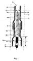
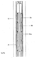
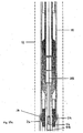
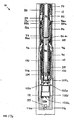
- Fig. 1 is a schematic fragmentary cross-sectional illustration of an expandable tubular member and expansion cone assembly running through a mono diameter well bore casing formed according to one aspect to the invention.
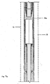
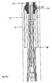
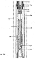
- Fig. 2 is a schematic fragmentary cross-sectional illustration of an expandable tubular member and expansion cone assembly forming a bell portion of the mono diameter well bore casing of Fig. 1 according to one aspect to the invention.
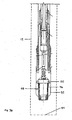
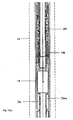
- Fig. 3 is a schematic fragmentary cross-sectional illustration of an expandable tubular member and expansion cone assembly forming a mono diameter portion of the mono diameter wellbore casing of Figs. 1 and 2 according to another aspect to the invention.
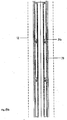
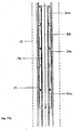
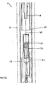
- Fig. 4 is a schematic fragmentary cross-sectional illustration of an expandable tubular member, a gripping mechanism within the tubular member, an actuator, an expansion cone assembly for forming a mono diameter casing and a float shoe supporting the tubular member for running into a wellbore.
- Fig. 5 is a schematic fragmentary cross-sectional illustration of an expandable tubular member, a gripping mechanism engaging the tubular member, an actuator and expansion cone assembly for forming a mono diameter casing, with the tubular member lifted off the bottom of the wellbore and with the expansion cone assembly pushed by the actuator into an open wellbore.
- Fig. 6 is a schematic fragmentary cross-sectional illustration of the expansion -cone assembly expanded for radially expanding and plastically deforming the expandable tubular member.
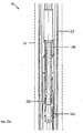
- Figs. 7a -7e are fragmentary cross-sectional illustrations of the placement of an exemplary embodiment of an apparatus for forming a mono diameter wellbore casing within a wellbore that traverses a subterranean formation.
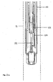
- Figs. 8a - 8e are fragmentary cross-sectional illustrations of the apparatus of Figs. 7a -7e after placement on the bottom of the wellbore.
- Figs. 9a -9e are fragmentary cross-sectional illustrations of the apparatus of Figs. 8a - 8e after placing a ball or dart within the ball or dart seat to initiate the radial expansion and plastic deformation of the expandable tubular member.
- Figs. 10a -10e are fragmentary cross-sectional illustrations of the apparatus of Figs. 9a-9e after the initiation of the radial expansion and plastic deformation of the aluminum sleeve within the shoe.
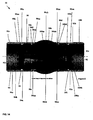
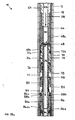
- Fig. 11a -11b is a fragmentary cross-sectional illustration of an exemplary embodiment of an apparatus for radially expanding and plastically deforming a tubular member that includes an adjustably expandable expansion cone assembly.
- Fig. 12 is a fragmentary cross-sectional illustration of an upper cone portion of the apparatus for radially expanding and plastically deforming a tubular member of Figs. 11a - 11b.
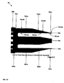
- Fig. 13 is a fragmentary cross-sectional illustration of a lower cone portion of the apparatus for radially expanding and plastically deforming a tubular member of Figs. 11a-11b.
- Fig. 14 is a fragmentary cross-sectional illustration of an overlapping portion of the apparatus for radially expanding and plastically deforming a tubular member of Figs. 11a - 11b, 12 and 13.
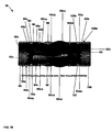
- Fig. 15 is a fragmentary cross-sectional and perspective illustrations of the upper cam assembly of the apparatus for radially expanding and plastically deforming a tubular member of Figs. 11a - 11b.
- Fig. 16 is a fragmentary cross-sectional and perspective illustrations of the lower cam assembly of the apparatus for radially expanding and plastically deforming a tubular member of Figs. 11a -11b.
- Fig. 17a -17b is a fragmentary cross-sectional illustration of an exemplary embodiment of an apparatus for radially expanding and plastically deforming a tubular member that includes an adjustably expandable expansion cone assembly of Figs. 11a - 11b activated for cementing.
- Fig. 18a -18b is a fragmentary cross-sectional illustration of an exemplary embodiment of an apparatus for radially expanding and plastically deforming a tubular member that includes an adjustably expandable expansion cone assembly of Figs. 11a - 11b activated for adjusting the expansion diameter.
- Fig. 19 is a fragmentary cross-sectional illustration of an overlapping portion of the apparatus for radially expanding and plastically deforming a tubular member adjusted to an intermediate expansion diameter.
- Fig. 20a -20b are fragmentary cross sectional illustrations of the apparatus of Figs. 10d-10e after the completion of the radial expansion and plastic deformation of the aluminum sleeve within the shoe.
- Figs. 21a -21b are fragmentary cross-sectional illustrations of the apparatus of Figs. 20a -20b after displacing the sliding sleeve valve within the shoe to permit circulation around the ball or dart.
- Figs. 22a -22b are fragmentary cross sectional illustrations of the apparatus of Figs. 21a -21b during the injection of cement into the annulus between the radially expanding tubular member and the wellbore using the bypass circulation provided by the displaced sliding sleeve valve within the shoe.
- Figs. 1- 6 illustrate several illustrative embodiments of a device and method for forming a mono diameter well bore casing using an expansion assembly including two cone diameters, one of which is larger than the other for forming a bell (sometimes called a skirt) section for overlapping expandable tubular members so that the effort required for the expansion assembly to expanded two overlapping tubular members is reduced. The other cone diameter is sized for expanding the tubular members to the desired diameter along the length of the tubular member thereby resulting in a mono-diameter well bore casing. The two diameters may be provided with a conventional adjustable size expansion cone having two expansion diameters, one larger than the other. The larger diameter is adjusted to a smaller diameter after a bell section of an expandable tubular member is formed and then the remainder of the expandable tubular member is expanded to a the desired internal diameter for the mono diameter well bore casing. Conventional adjustably expandable cones can be used according to the invention. In several alternative embodiments, the invention is implemented as described in Figs. 7a -7e, 8a -8e, 9a- 9e, 10a -10e, 11a -11b and 17a-17b, 18a-18b and 19a-19b with an exemplary adjustably expandable cone assembly as described in greater detail herein with reference to Figs. 11a - 11b, 12, 13, 14, 15 and 16. In other alternative embodiments the adjustably expandable cones of the invention may be implemented or using the methods and/or apparatus disclosed one or more of the following: (1)
U.S. patent application serial no. 09/454,139 , attorney docket no. 25791.03.02, filed on 12/3/1999, (2)U.S. patent application serial no. 09/510,913 , attorney docket no. 25791.7.02, filed on 2/23/2000, (3)U.S. patent application serial no. 09/502,350 , attorney docket no. 25791.8.02, filed on 2/10/2000, (4)U.S. patent no. 6,328,113 , (5)U.S. patent application serial no. 09/523,460 , attorney docket no. 25791.11.02, filed on 3/10/2000, (6)U.S. patent application serial no. 09/512,895 , attorney docket no. 25791.12.02, filed on 2/24/2000, (7)U.S. patent application serial no. 09/511,941 , attorney docket no. 25791.16.02, filed on 2/24/2000, (8)U.S. patent application serial no. 09/588,946 , attorney docket no. 25791.17.02, filed on 6/7/2000, (9)U.S. patent application serial no. 09/559,122 , attorney docket no. 25791.23.02, filed on 4/26/2000, (10)PCT patent application serial no. PCT/US00/18635 , attorney docket no. 25791.25.02, filed on 7/9/2000, (11)U.S. provisional patent application serial no. 60/162,671 , attorney docket no. 25791.27, filed on 11/1/1999, (12)U.S. provisional patent application serial no. 60/154,047 , attorney docket no. 25791.29, filed on 9/16/1999, (13)U.S. provisional patent application serial no. 60/159,082 , attorney docket no. 25791.34, filed on 10/12/1999, (14)U.S. provisional patent application serial no. 60/159,039 , attorney docket no. 25791.36, filed on 10/12/1999, (15)U.S. provisional patent application serial no. 60/159,033 , attorney docket no. 25791.37, filed on 10/12/1999, (16)U.S. provisional patent application serial no. 60/212,359 , attorney docket no. 25791.38, filed on 6/19/2000, (17)U.S. provisional patent application serial no. 60/165,228 , attorney docket no. 25791.39, filed on 11/12/1999, (18)U.S. provisional patent application serial no. 60/221,443 , attorney docket no. 25791.45, filed on 7/28/2000, (19)U.S. provisional patent application serial no. 60/221,645 , attorney docket no. 25791.46, filed on 7/28/2000, (20)U.S. provisional patent application serial no. 60/233,638 , attorney docket no. 25791.47, filed on 9/18/2000, (21)U.S. provisional patent application serial no. 60/237,334 , attorney docket no. 25791.48, filed on 10/2/2000, (22)U.S. provisional patent application serial no. 60/270,007 , attorney docket no. 25791.50, filed on 2/20/2001, (23)U.S. provisional patent application serial no. 60/262,434 , attorney docket no. 25791.51, filed on 1/17/2001, (24)U.S. provisional patent application serial no. 60/259,486 , attorney docket no. 25791.52, filed on 1/3/2001, (25)U.S. provisional patent application serial no. 60/303,740 , attorney docket no. 25791.61, filed on 7/6/2001, (26)U.S. provisional patent application serial no. 60/313,453 , attorney docket no. 25791.59, filed on 8/20/2001, (27)U.S. provisional patent application serial no. 60/317,985 , attorney docket no. 25791.67, filed on 9/6/2001, (28) U.S. provisional patent application serial no. 60/3318,386, attorney docket no. 25791.67.02, filed on 9/10/2001, (29)U.S. utility patent application serial no. 09/969,922 , attorney docket no. 25791.69, filed on 10/3/2001, (30)U.S. utility patent application serial no. 10/016,467 , attorney docket no. 25791.70, filed on 12/10/2001, (31)U.S. provisional patent application serial no. 60/343,674 , attorney docket no. 25791.68, filed on 12/27/2001, (32)U.S. provisional patent application serial no. 60/346,309 , attorney docket no 25791.92, filed on 1/7/2002, (33)U.S. provisional patent application serial no. 60/372,048 , attorney docket no. 25791.93, filed on 4/12/2002, (34)U.S. provisional patent application serial no. 60/380,147 , attorney docket no. 25791.104, filed on 5/6/2002, (35)U.S. provisional patent application serial no. 60/387,486 , attorney docket no. 25791.107, filed on 6/10/2002, (36)U.S. provisional patent application serial no. 60/387,961 , attorney docket no. 25791.108, filed on 6/12/2002, (37)U.S. provisional patent application serial no. 60/391,703 , attorney docket no. 25791.90, filed on 6/26/2002, (38)U.S. provisional patent application serial no. 60/397,284 , attorney docket no. 25791.106, filed on 7/19/2002, (39)U.S. provisional patent application serial no. 60/398,061 , attorney docket no. 25791.110, filed on 7/24/2002, (40)U.S. provisional patent application serial no, 60/405,610 , attorney docket no. 25791.119, filed on 8/23/2002, (41)U.S. provisional patent application serial no. 60/405,394 , attorney docket no. 25791.120, filed on 8/23/2002, (42)U.S. provisional patent application serial no. 60/412,177 , attorney docket no. 25791.117, filed on 9/20/2002, (43)U.S. provisional patent application serial no. 60/412,653 , attorney docket no. 25791.118, filed on 9/20/2002, (44)U.S. provisional patent application serial no. 60/412,544 , attorney docket no. 25791.121, filed on 9/20/2002, (45)U.S. provisional patent application serial no. 60/412,187 , attorney docket no. 25791.128, filed on 9/20/2002, (46)U.S. provisional patent application serial no. 60/412,187 , attorney docket no. 25791.127, filed on 9/20/2002, (47)U.S. provisional patent application serial no. 60/412,487 , attorney docket no. 25791.112, filed on 9/20/2002, and (48)U.S. provisional patent application serial no. 60/412,488 , attorney docket no. 25791.114, filed on 9/20/2002, the disclosures of which are incorporated herein by reference. - Fig. 1 shows a schematic illustration of an
apparatus 10 in awellbore 12 with anexpandable tubular member 14 and anexpansion cone assembly 16 supported by a tubular support 30 (such as a drill pipe 30), all supported by afloat shoe 32 for running into awellbore 12 through a plurality ofcasing sections diameter wellbore casing 18 in the process of being formed, according to one aspect to the invention. The existingcasing 18sections tubular members 14 and according to the teachings of the present invention includemono diameter portions bell portions 22a and 22b having a second inside diameter inside diameter ID2 and a length L. There is an overlappingportion 26 where the bell portions 22a overlap of thecasing section 18b. - Fig. 2 shows a schematic illustration of the
expandable tubular member 14, acted upon by alarge cone 20 of theexpansion cone assembly 16 to expand the diameter of the lower end of theexpandable tubular member 14 to form abell portion 22. Thebell portion 22 is formed by thelarge cone 20 of theexpansion cone assembly 16 that has an adjustable cone diameter sufficiently large so that the resulting expanded inside diameter of thebell portion 20 is at least slightly larger than a desired inside diameter of the monodiameter wellbore casing 18. The length of thebell portion 20 depends upon the desired length of overlappinglengths 26 between nestedcasing sections overlap length 26 and therefore thebell portion 22 may have a length up to about 30.5m (100 feet) or up to about 45.7m (150 feet). - Fig. 3 shows a schematic illustration of the
expandable tubular member 14 of Fig. 2, with theexpansion cone assembly 16 positioned for expanding theexpandable tubular member 14 to the desired mono diameter at the portion 28 above thebell portion 22. In this configuration the diameter of the largeadjustable cone 20 is collapsed, or is other wise adjusted, to a smaller diameter. Anothercone 24, having a diameter smaller than the large diameter ofcone 20, is provided for radially expanding thetubular member 14 to the desired inside diameter of the mono diameter wellbore casing. Thewellbore casing section 18c of the mono diameter well bore casing 18 of Figs. 1 and 2, overlaps with thewellbore casing section 18b along the overlappinglength 26 and at thebell portion 22b. The inside diameter or thebell portion 22 and the outside diameter of the mono diameter portion 28 are the same to provide a tight fitting junction between the nestedsections 18a, b, c and etc. For example, where theexpandable tubular member 14 has a wall thickness of about 0.35 inches and for the desired inside diameter of the mono diameter wellbore casing is about 10.3 inches, after expansion, the inside diameter of the bell portion might be about 11.0 inches, or slightly less to provide a tight fit between the overlapping portions of thecasing sections 18a, b, c and etc. - The
large diameter cone 20 can be positioned above, below or effectively at the same position as thesmall diameter cone 24, without departing from certain aspects of the invention. Also, it will be understood by those of ordinary skill in the art, and based upon this disclosure, that the large diameter corresponding to the inside diameter of the bell portion can be provided by a first collapsible oradjustable cone 22, that provides the desired bell portion diameter and that can be collapsed to a smaller diameter, together with asecond cone 24 that provides the diameter for forming the mono diameter well bore casing. It will also be understood that in an alternative embodiment the expansion to the mono diameter can be provided by adjusting the diameter ofcone 22 to effectively become thesmaller diameter cone 24 having a diameter corresponding to the desired mono diameter. It will further be understood that in another alternative embodiment thecone 24 is adistinct cone 24 either fixed at the desired mono diameter size or expandable to the desired mono diameter size. - Fig. 4 shows a schematic mono diameter
casing forming apparatus 10, further depicting one arrangement of a mechanism for activating theexpansion cone assembly 16 to expand thetubular member 14. Theapparatus 10 is shown in a configuration for running into awellbore 12. Adrill pipe 30 supports theapparatus 10, as it is running down into thewellbore 12, with aconnected float shoe 32. Thedrill pipe 30 may be a conventional drill pipe or other conventional down hole tubular support member. The float shoe may be a conventional float shoe or other tool guiding structure that serves the describe purpose attached to the drill pipe or other tubular support member. Thefloat shoe 32 thus supports the new expandabletubular member 14 that is to be added to and expanded for engagement with the lower end of the monodiameter wellbore casing 18 that has been previously formed. Angripping tool 34, sometimes called an anchor that may be a device as shown or a conventional gripping tool or anchor, is provided to hold theexpandable tubular member 14 fixed relative to one end of ahydraulic actuator 36, sometimes called a force multiplier mechanism that may be a device as shown or a conventional actuator or force multiplier. Thehydraulic actuator 36 is configured and actuatable for moving theexpansion cone assembly 16 relative to theexpandable member 14, either intension using sub 36a or incompression using sub 36b. - Fig. 5 schematically shows an embodiment of the mono diameter
casing forming apparatus 10, with thegripping mechanism 34 engaging thetubular member 14, with thetubular member 14 lifted off the bottom of the well bore 12 and with theexpansion cone 16 pushed byactuator 36 into theopen wellbore 12. Aconventional dart 53 or ball is dropped to seal thefloat shoe 32, or another conventional shut-off device such as a mechanical valve or a velocity valve is used and activated, so that fluid 38 forced through thedrill pipe 22 increases pressure to activate thegripping tool 26. When thedrill pipe 22 is set down at the bottom of the hole, thetension sub 36a of theactuator mechanism 36 is actuated. Pressure is increased in thedrill pipe 30 and thegripping mechanism 34 is engaged to anchor thetubular member 14.Compression sub 36b is activated to lift thetubular liner 14 off the bottom of the wellbore and to push thecone assembly 16 into the open hole ofwellbore 12. - Fig. 6 shows the
expansion cone assembly 16 expanded for radially expanding and plastically deforming theexpandable tubular member 14. The expansion of the expansion cone assembly is activated in a conventional manner, as with a dart 42 that is passed with the fluid 38 down through thedrill pipe 30 to thereby cause appropriate port alignment and/or appropriate valve activation for theexpansion cone assembly 16. An optional sacrificialprotective sleeve 40 that protects theexpansion cone assembly 16 while it is running into the wellbore breaks off when the expansion cone assembly is expanded. Theprotective sleeve 40 may be formed of a plastic or composite material so that the sacrificial protective sleeve easily breaks off and does not interfere with the expansion of thetubular member 14. - In an exemplary embodiment, as illustrated in Figs. 7a -7e, an
apparatus 10 for forming a monodiameter wellbore casing 18 is positioned within awellbore 12. Theapparatus 10 includes, among other things, anexpandable tubular member 14 and an adjustableexpansion cone assembly 16. During placement of theapparatus 10 within thewellbore 12, theexpandable tubular member 14 may be supported by thegrip tool 34 and/or theexpansion cone assembly 16 and/or thefloat shoe 32. - In an exemplary embodiment, as illustrated in Figs. 8a - 8e, the
apparatus 10 is then positioned into contact with the bottom 44 of thewellbore 12. As a result, ashear pin 46 is sheared and adog locking sleeve 48 is driven upwardly thereby displacing a plurality ofdogs 50 outwardly in the radial direction in a conventional manner. - In an exemplary embodiment, as illustrated in Figs. 9a - 9e, a
ball 52 or conventional dart may then be placed within the ball or dart seat 54 of the apparatus by injectingfluidic material 38 into theapparatus 10. As a result, the flow offluidic material 38 through thefloat shoe 32 is blocked. The expansion cone assembly is also actuated in a conventional manner, for example with the pressure caused by theball 52 or a dart 42 (as shown in Fig. 6 above), to expand to the large diameter for expanding the bell. Pressure builds and theactuator 36 is activated in tension to draw thelarge cone 20 upward partially through theexpandable tubular member 14. Pressure can be released and reactivated in theactuator 36 and grippingtool 34 to repeatedly stroke thelarge cone 20 of theexpansion cone assembly 16 along the desired overlapping length L of the casing to thereby form thebell portion 22 of the casing. - In an exemplary embodiment, as illustrated in Figs. 10a -10e, the
large diameter cone 20 is actuated to collapse or adjust to asmaller diameter cone 24 corresponding -to the desired diameter of themono diameter casing 18, using conventional actuation, for example, increased fluidic pressure and a rupture disc in an appropriate port (not shown) or anadditional dart 56 injected with thefluidic material 38 into theapparatus 10 to aconventional dart seat 58. The grippingtool 34 is activated to lock the top end of thehydraulic actuator 36 to theexpandable tubular member 14. The injectedfluidic material 38 also causes theadjustable cone 24 to reach the desired diametrical size for forming themono diameter casing 18. The continued injection of thefluidic material 38 furthermore increases the operating pressure within the apparatus thereby causing thehydraulic actuator 36 to pull theexpansion cone 24 into theexpandable tubular member 14. As a result, theexpandable tubular member 14 is radially expanded. - The continued upward movement of the expansion cone pulls the
float shoe 32 to the bottom end of the radially expandedtubular member 14. As a result, the end of the radially expandedtubular member 14 will impact thedogs 50 thereby preventing thefloat shoe 32 from moving further in the upward direction. The continued upward movement of the expansion cone then will pull asleeve expander cone 60 for thesleeve 62 upwardly thereby radially expanding a sleeve of the float shoe within the float shoe. - In one exemplary embodiment, as illustrated in Figs. 11 a -11 b, 12, 13, 14, 15 and 16, the
expansion cone assembly 16 is adjustable for providing two outside diameters, one outside diameter larger than the other outside diameter. The construction of the expandable cone assembly may also be constructed in accordance with the principles and design disclosed inU.S. provisional patent application serial no. 60/387,961 , attorney docket no. 25791.108, filed on 6/12/2002, the disclosure of which is incorporated herein by reference. An exemplary embodiment includes atubular support member 64 coupled to an end of asafety collar 66 that defines apassage 66a and a recess 66b, at one end for receiving the end of thetubular support member 14, and recesses 66c and 66d at another end. - A
torque plate 68 is received within and is coupled to the recess 66c of thesafety collar 66 that defines apassage 68a and a plurality of meshingteeth 68b at one end. An end of anupper mandrel collar 70 is received with and is coupled to therecess 66d of thesafety collar 66 proximate an end of thetorque plate 68 that defines apassage 68a. Torque pins 72a and 72b further couple the end of theupper mandrel collar 70 to the end of thesafety collar 66. - An end of an
upper mandrel 74 is received within and is coupled to theupper mandrel collar 70 that defines a passage 74a, a plurality of meshing teeth 74b that mate with and transmit torque to and from the meshingteeth 68b of thetorque plate 68, and anexternal flange 74c at another end. - An
upper packer cup 76 mates with, receives and is coupled to theupper mandrel 74 proximate the end of theupper mandrel collar 70. In an exemplary embodiment, theupper packer cup 76 is a conventional Guiberson™ packer cup. Anupper spacer sleeve 78 mates with, receives, and is coupled to theupper mandrel 74 proximate an end of theupper packer cup 76. Alower packer cup 80 mates with, receives and is coupled to theupper mandrel 74 proximate an end of theupper spacer sleeve 78. In an exemplary embodiment, thelower packer cup 80 is a conventional Guiberson™ packer cup. Alower spacer sleeve 82 mates with, receives, and is coupled to theupper mandrel 74 proximate an end of thelower packer cup 80 and theexternal flange 74c of the upper mandrel. A retainingsleeve 84 mates with, receives, and is coupled to an end of the lower spacer sleeve proximate theexternal flange 74c of theupper mandrel 74. - An end of a
lower mandrel 86 defines arecess 86a that mates with, receives, and is coupled to theexternal flange 74c of theupper mandrel 74, arecess 86b that mates with, receives, and is coupled to the end of the upper mandrel, a passage 86c, and anexternal flange 86d including circumferentially spaced apart meshing teeth 86da on an end face of the external flange. Torque pins 88a and 88b further couple therecess 86a of the end of thelower mandrel 86 to theexternal flange 74c of theupper mandrel 74. During operation, the torque pins 88a and 88b transmit torque loads between therecess 86a of the end of thelower mandrel 86 and theexternal flange 74c of theupper mandrel 74. - An
upper cam assembly 90 includes atubular base 90a for receiving and mating with thelower mandrel 86 that includes an external flange 90aa, a plurality of circumferentially spaced apart meshingteeth 90b that extend from one end of the tubular base in the longitudinal and radial directions for engaging the meshing teeth 86da of the end face of theexternal flange 86d of thelower mandrel 86, and a plurality of circumferentially spaced apartcam arms 90c that extend from the other end of the tubular base in the opposite longitudinal direction and mate with and receive thelower mandrel 86. During operation, the meshing teeth 86da of the end face of theexternal flange 86d of thelower mandrel 86 transmit torque loads to the meshingteeth 90b of theupper cam assembly 90. Each of thecam arms 90c include an inner portion 90ca extending from thetubular base 90a that has arcuate cylindrical inner 90caa and outer 90cab surfaces, a tapered intermediate portion extending from the inner portion 90cb that has an arcuate cylindrical inner surface 90cba and an arcuate conical outer surface 90bbb, and an outer portion 90cc extending from the intermediate portion 90cc that has arcuate cylindrical inner 90cca and outer surfaces 90ccb. - A
lower cam assembly 92 includes atubular base 92a for receiving and mating with thelower mandrel 86 that includes an external flange 92aa, a plurality of circumferentially spaced apart meshingteeth 92b that extend from one end of the tubular base in the longitudinal and radial directions, and a plurality of circumferentially spaced apartcam arms 92c that extend from the other end of the tubular base in the opposite longitudinal direction and mate with and receive thelower mandrel 86. Each of thecam arms 92c include an inner portion 92ca extending from thetubular base 92a that has arcuate cylindrical inner 92caa and outer 92cab surfaces, a tapered intermediate portion 92cb extending from the inner portion 92ca that has an arcuate cylindrical inner surface 92cba and an arcuate conical outer surface 92cbb, and an outer portion 92cc extending from the intermediate portion 92cb that has arcuate cylindrical inner 92cca and outer 92ccb surfaces. - In an exemplary embodiment, the upper and lower cam assemblies, 90 and 92, are substantially identical. In an exemplary embodiment, the
cam arms 90c of theupper cam assembly 90 interleave the-cam arms 92c of thelower cam assembly 92. Furthermore, in an exemplary embodiment, thecam arms 90c of the upper cam assembly also overlap with thecam arms 92c of thelower cam assembly 92 in the longitudinal direction thereby permitting torque loads to be transmitted between the upper and lower cam assemblies. - A plurality of upper
expansion cone segments 96 are interleaved among thecam arms 90c of theupper cam assembly 90. Each of the upperexpansion cone segments 96 include inner portions 96a having arcuate cylindrical inner surfaces 96aa, and an arcuate cylindrical outer surface 96ab,intermediate portions 96b extending from the interior portions that have an arcuate conical inner surface 96ba and arcuate cylindrical and spherical outer surfaces, 96bb, and outer portions 96c having arcuate cylindrical inner and outer surfaces, 96ca and 96cb. In an exemplary embodiment, the outer surfaces 96ab of the inner portions 96a of the upperexpansion cone segments 96 definehinge grooves 96d that receive and are pivotally mounted upon the internal -flange 94d of the upper retainingsleeve 94. - The arcuate inner cylindrical surfaces of the inner portion 96a mate with and receive the
lower mandrel 86, the arcuate inner cylindrical surfaces of the inner portion 96a also mate with and receive the arcuate cylindrical outer surfaces of the outer portions 92cc of the correspondingcam arms 92c of thelower cam assembly 92, and the arcuate inner conical surfaces 96ba of the inner portion 96a mate with and receive the arcuate conical outer surfaces of the intermediate portions 92cb of the correspondingcam arms 92c of thelower cam assembly 92. - A plurality of lower
expansion cone segments 98 are interleaved among, and overlap, the upperexpansion cone segments 96 and thecam arms 90c of thelower cam assembly 90. In this manner, torque loads may be transmitted between the upper and lower expansion cone segments, 96 and 98. Each of the lowerexpansion cone segments 98 include inner portions 98a having arcuate cylindrical inner surfaces, 98aa, and an arcuate cylindrical outer surface 98ab,intermediate portions 98b extending from the interior portions that have an arcuate conical inner surface 98ba and arcuate cylindrical and spherical outer surfaces, 98bb, and outer portions 98c having arcuate cylindrical inner and outer surfaces, 98ca and 98cb. In an exemplary embodiment, the outer surfaces 98ab of the inner portions 98a of the upperexpansion cone segments 98 define hinge grooves 98aba that receive and are pivotally mounted upon theinternal flange 100d of alower retaining sleeve 100. - The arcuate inner cylindrical surfaces 98aa mate with and receive the
lower mandrel 86, the arcuate inner cylindrical surfaces 98aa also mate with and receive the arcuate cylindrical outer surfaces of the outer portions 90cc of the correspondingcam arms 90c of theupper cam assembly 90, and the arcuate inner conical surfaces 98ba mate with and receive the arcuate conical outer surfaces of the intermediate portions 90cb of the correspondingcam arms 90c of thelower cam assembly 90. - In an exemplary embodiment, the geometries of the upper and lower
expansion cone segments expansion cone segments 96 are tapered in the longitudinal direction from the ends of theintermediate portions 96b to the ends of the outer portions 96c, and the lowerexpansion cone segments 98 are tapered in the longitudinal direction from the ends of theintermediate portions 98b to the ends of the outer portions 98c. In an exemplary embodiment, when the upper and lower expansion segments, 96 and 98, are positioned in a fully expanded position, the arcuate cylindrical outer surfaces 96ab of the upper and lowerexpansion cone segments 96 define a contiguous cylindrical surface, the arcuate spherical outer surfaces of the upper and lower expansion cone segments, 96bb and 98bb, define a contiguous arcuate spherical surface, and the arcuate cylindrical outer surfaces of the upper and lower expansion cone segments define a contiguous cylindrical surface. - An end of a
lower retaining sleeve 100 defines apassage 100a for receiving and mating with the outer circumferential surfaces of the external flange 92aa and the meshingteeth 92b of thelower cam assembly 92, and an innerannular recess 100b, and includes aninternal flange 100c for retaining the external flange of the lower cam assembly, and aninternal flange 100d at one end of the lower retaining sleeve that includes a rounded interior end face for mating with corresponding hinge grooves of the lowerexpansion cone segments 98 thereby pivotally coupling the lower expansion cone segments to the lower retaining sleeve. - In an exemplary embodiment, the arcuate cylindrical outer surfaces of the upper
expansion cone segments 96 and the arcuate cylindrical outer surfaces of the lowerexpansion cone segments 98 are aligned with the outer surface of the upper retainingsleeve 94. In an exemplary embodiment, the arcuate cylindrical outer surfaces of the upperexpansion cone segments 96 and the arcuate cylindrical outer surfaces of the lower expansion cone segments are aligned with the outer surface of thelower retaining sleeve 100. - An end of a
float shoe adaptor 102 that includes a plurality of circumferentially spaced apart meshingteeth 102a for engaging the meshingteeth 92b of thelower cam assembly 92 is received within and threadably coupled to an end of thelower retaining sleeve 100 that defines apassage 102b at one end for receiving an end of thelower mandrel 86, apassage 102c having a reduced inside diameter at another end, a plurality ofradial passages 102d at the other end, and includes aninternal flange 102e, and atorsional coupling 102f at the other end that includes a plurality of torsional coupling members 102fa. During operation, the meshingteeth 92b of thelower cam assembly 92 transmit toque loads to and from the meshingteeth 102a of the float shoe adaptor. - An end of a retaining
sleeve 104 abuts the end face of thetubular base 92a of thelower cam assembly 92 and is received within and mates with thepassage 102b of thefloat shoe adaptor 102 that defines apassage 104a for receiving an end of thelower mandrel 86, athroat passage 104b including aball valve seat 104c, and includes aflange 104d, and another end of the retaining sleeve, having a reduced outside diameter, is received within and mates with thepassage 102c of thefloat shoe adaptor 102. - A
stop nut 106 receives and is threadably coupled to the end of thelower mandrel 86 within thepassage 104a of the retainingsleeve 104, andshear pins 108 releasably couple thestop nut 106 to the retainingsleeve 104. Lockingdogs 110 are positioned within an end of the retainingsleeve 104 that receive and are releasably coupled to thelower mandrel 86, and a disc shapedadjustment shim 112 receives thelower mandrel 86 and is positioned within an end of the retainingsleeve 104 between the opposing ends of thetubular base 92a of theupper cam assembly 92 and the locking dogs 110.Burst discs 114 are releasably coupled to and positioned within theradial passages 102d of thefloat shoe adaptor 102. - An end of a
float shoe 116 mates with and is releasably coupled to thetorsional coupling 102f of thefloat shoe adaptor 102 that defines a passage 116a and avalveable passage 116b. In this manner torsional loads may be transmitted between thefloat shoe adaptor 102 and thefloat shoe 116. An end of anexpandable tubular member 14 that surrounds thetubular support member 64, thesafety collar 66, theupper mandrel collar 70, theupper packer cup 76, thelower packer cup 80, thelower mandrel 86, the upper expansion cone-segments 96, the lowerexpansion cone segments 98, and thefloat shoe adaptor 102, is coupled to and receives an end of thefloat shoe 116 and is movably coupled to and supported by the arcuate spherical external surfaces, 96bb and 98bb, of the upper and lower expansion cone segments, 96 and 98. - During operation, the
apparatus 10 is at least partially positioned within a preexisting structure such as, for example, a borehole 12 that traverses a subterranean formation that may include a preexistingwellbore casing 18. The borehole 12 may be oriented in any position, for example, from vertical to horizontal. Afluidic material 38 is then injected into theapparatus 10 through thepassages expandable tubular member 14 and theborehole 12. In an exemplary embodiment, thefluidic material 104 is a hardenable fluidic sealing material. In this manner, an annular sealing layer may be formed within the annulus between theexpandable tubular member 14 and theborehole 12. - As illustrated in Figs. 17a and 17b, a
ball 55 is then be positioned within and blocking thevalveable passage 116b of thefloat shoe 116 by injecting afluidic material 38 into theapparatus 10 through thepassages passage 102c bursts open theburst discs 114 positioned within theradial passages 102d of thefloat shoe adaptor 102. The continued injection of thefluidic material 38 thereby pressurizes the interior of theexpandable tubular member 14 below thelower packer cup 80 thereby displacing the upper and lower expansion cone segments, 96 and 98, upwardly relative to thefloat shoe 116 and theexpandable tubular member 14. As a result, theexpandable tubular member 14 is plastically deformed and radially expanded. Thus, theburst discs 114 sense the operating pressure of the injectedfluidic material 38 within thepassage 102c and thereby control the initiation of the radial expansion and plastic deformation of theexpandable tubular member 14. - In an exemplary embodiment, any leakage of the pressurized
fluidic material 38 past thelower packer cup 80 is captured and sealed against further leakage by theupper packer cup 76. In this manner, thelower packer cup 80 provides the primary fluidic seal against the interior surface of theexpandable tubular member 14, and theupper packer cup 76 provides a secondary, back-up, fluidic seal against the interior surface of the expandable tubular member. Furthermore, because thelower packer cup 80 and/or theupper packer cup 76 provide a fluid tight seal against the interior surface of theexpandable tubular member 14, the upper and lower expansion cone segments, 96 and 98, are pulled upwardly through the expandable tubular member by the axial forces created by the packer cups. - In an exemplary embodiment, during the radial expansion process, the interface between the arcuate spherical external surfaces, 96bb and 98bb, of the upper and lower expansion cone segments, 96 and 98, and the interior surface of the
expandable tubular member 14 is not fluid tight. As a result, thefluidic material 38 may provide lubrication to the entire extent of the interface between the cylindrical external surfaces, 96bba and 98cb, and the arcuate spherical external surfaces, 96bb and 98bb, of the upper and lower expansion cone segments, 96 and 98, and the interior surface of theexpandable tubular member 14. Moreover, experimental test results have indicated the unexpected result that the required operating pressure of thefluidic material 38 for radial expansion of theexpandable tubular member 14 is less when the interface between the cylindrical external surfaces, 96bba and 98cb,- and the arcuate spherical external surfaces, 96bb and 98bb, of the upper and lower expansion cone segments, 96 and 98, and the interior surface of theexpandable tubular member 14 is not fluid tight. Furthermore, experimental test results have also demonstrated that the arcuate spherical external surface provided by the arcuate spherical external surfaces, 96bb and 98bb, of the upper and lower expansion cone segments, 96 and 98, provides radial expansion and plastic deformation of theexpandable tubular member 14 using lower operating pressures versus an expansion cone having a conical outer surface. - In an exemplary embodiment, as illustrated in Figs. 18a, 18b and 19, the upper and lower expansion cone segments, 96 and 98, may then be adjusted to a desired expansion diameter by placing a
ball 57 within theball valve seat 104c of thethroat passage 104b of the retainingsleeve 104. The continued injection of thefluidic material 38, after the placement of theball 57 within theball valve seat 104c, creates a differential pressure across theball 57 thereby applying a downward longitudinal force onto the retainingsleeve 104 thereby shearing the shear pins 108. As a result, the retainingsleeve 104 is displaced in the downward longitudinal direction relative to thefloat shoe adaptor 102 thereby permitting the lockingdogs 110 to be displaced outwardly in the radial direction. The outward radial displacement of the lockingdogs 110 disengages the locking dogs from engagement with thelower mandrel 86. Thus, the shear pins 108 sense the operating pressure of the injectedfluidic material 38 within thethroat passage 104b and thereby controlling the initiation of the-collapsing of the upper and lower expansion cone segments, 96 and 98 to a smaller diameter. - The continued injection of the
fluidic material 38 continues to -displace the retainingsleeve 104 in the downward longitudinal direction relative to thefloat shoe adaptor 102 until theexternal flange 104d of the retainingsleeve 104 impacts, and applies a downward longitudinal force to, theinternal flange 102e of the float shoe adaptor. As a result, thefloat shoe adaptor 102 is then also displaced in the downward longitudinal direction relative to thelower mandrel 86. The downward longitudinal displacement of thefloat shoe adaptor 102 relative to thelower mandrel 86 causes thelower cam assembly 92, the lowerexpansion cone segments 98, and thelower retaining sleeve 100, which are rigidly attached to the float shoe adaptor, to also be displaced downwardly in the longitudinal direction relative to thelower mandrel 86, theupper cam assembly 90, and the upperexpansion cone segments 96. The downward longitudinal displacement of thelower cam assembly 92 relative to the upperexpansion cone segments 96 causes the upper expansion cone segments to slide down the conical external surfaces 92cbb of the lower cam assembly and thereby pivot inwardly in the radial direction about theinternal flange 94d of the upper retainingsleeve 94. The downward longitudinal displacement of the lowerexpansion cone segments 98 relative to theupper cam assembly 90 causes the lowerexpansion cone segments 98 to slide down the external conical surfaces 90cbb of the upper cam assembly and thereby pivot inwardly in the radial direction about theinternal flange 100d of the lower retaining sleeve. As a result of the inward radial movement of the upper and lower expansion cone segments, 96 and 98, the arcuate external spherical surfaces, 96bb and 98bb, of the upper and lower expansion cone segments, 96 and 98, provide outer arcuate expansion surfaces having a smaller diameter. - The downward longitudinal movement of the retaining
sleeve 94 andfloat shoe adaptor 102 relative to thelower mandrel 86 is stopped when thestop nut 106 impacts the locking dogs 110. At this point, theapparatus 10 may then be removed from the interior of theexpandable tubular member 14. - Thus, the
apparatus 10 may be removed from theexpandable tubular member 14 prior to the complete radial expansion and plastic deformation of the expandable tubular member by controllably collapsing the upper and lower expansion cone segments, 96 and 98. As a result, theapparatus 10 provides the following benefits: (1) the apparatus is removable when expansion- problems are encountered; (2) lower expansion forces are required because the portion of theexpandable tubular member 14 between the packer cups, 76 and 80, and the expansion cone segments is exposed to the expansion fluid pressure; (3) the expansion cone segments can be run down through the expandable tubular member, prior to radial expansion, and then the expansion cone segments can be expanded; (4) the expansion cone segments can be expanded to one diameter for forming a bell portion; and (5) the expansion cone segments can be adjusted to a second diameter for expanding the remainder of the expandable tubular member. - In another exemplary embodiment, as illustrated in Figs. 20a - 20b, upward movement of the
apparatus 10 causes the expansion cone for thesleeve 60 to completely radially expand thesleeve 62 of thefloat shoe 32 and acementing probe 118 is pulled downward until stopped from further movement by the cementing probe locking ring 119. As a result of the complete radial expansion of the sleeve, the float - shoe is now firmly coupled to the end of the radially expanded-tubular member. - In an exemplary embodiment, as illustrated in Figs. 21a -21b, the
drill pipe 30 is lowered into thewellbore 12 until thecementing probe 118 stabs into theend 120 of the slidingsleeve valve 122 thereby permittingfluidic materials 38 to bypass around the dart orball 52. As a result, abypass flow path 124 is now provided for cement or otherfluidic materials 38 to flow around theball 52 or dart. - In an exemplary embodiment, as illustrated in Figs. 22a -22b, a hardenable
fluidic sealing material 38 such as, for example, cement, may then be injected into theapparatus 10. The cement flows through the interior of the apparatus, through thebypass flow path 124, and out through thefloat valve 126 into theannulus 128 between the radially expandedtubular member 22 and thewellbore 12. After thecement 38 has been injected into theannulus 128, thefloat valve 126 prevents the cement from flowing backwards into the apparatus. - After completing the injection of the cement into the annulus, the
drilling pipe 30 is then pulled upwardly out of thewellbore 12 thereby causing thecementing probe 118 to close the slidingsleeve valve 122. The radial expansion and plastic deformation of theexpandable tubular member 14 may then be continued by the resumed injection offluidic material 38 into theapparatus 10. In several alternative embodiments, the continued radial expansion and plastic deformation of theexpandable tubular member 14 may be provided by pressurizing the interior of theapparatus 10 below theexpansion cone 24 and/or by displacing theexpansion cone 24 upwardly using thehydraulic actuator 36. - After the cement has cured, the
float collar 32 may be drilled out and another expandable tubular member may then be radially expanded and plastically deformed within the wellbore with the upper end of the other tubular member overlapping with the lower end of the earlier expanded tubular member. In this manner, a mono diameter well bore casing may be formed that includes a plurality of radially expanded tubular members. - In several alternative embodiments, Guiberson™ cup seals may be added above the expansion cone that provide a fluid tight seal between the drill pipe and the interior surface of the expandable tubular member. In this manner, in the alternative embodiment, the fluid pressure below the cup seals pulls the expansion cone upwardly through the expandable tubular member.
- In several alternative embodiments, the expandable adjustable expansion cone assembly having two adjustable expansion diameters may be replaced with two separate adjustable cones one adjustable to a diameter corresponding to the desired bell portion diameter, and the other adjustable to a diameter corresponding to the desired diameter of the mono diameter casing.
- In several alternative embodiments, the expandable adjustable expansion cone assembly having two adjustable expansion diameters may be replaced with an adjustable cone that is adjustable to a diameter corresponding to the desired bell portion diameter, and a non-adjustable cone having a fixed diameter corresponding to the desired diameter of the mono diameter casing.
- In several alternative embodiments, a conventional rotary expansion device, a conventional compliant expansion device, and/or a conventional hydroforming expansion device may used instead of, or in combination with, the
expansion cone assembly 16. - In several alternative embodiments, one or more of the conventional commercially available expansion devices available from Weatherford International, Baker Hughes, Halliburton Energy Services, Schlumberger, and/or Enventure Global Technology may be used instead of, or in combination with, the
expansion cone assembly 16. - There has been disclosed in the several embodiments, an apparatus for radially expanding and plastically deforming an expandable tubular member from an initial inside diameter to a desired diameter of a mono diameter wellbore casing. The apparatus includes an upper tubular support member defining a first passage, one or more cup seals coupled to the exterior surface of the upper tubular support member for sealing an interface between the upper tubular support member and the expandable tubular member, an expansion cone assembly coupled to the upper tubular support member adjustable to one expansion diameter corresponding to the desired diameter of the bell portion of the wellbore casing for forming an expanded bell portion in the expandable tubular member and adjustable to another expansion diameter corresponding to the desired diameter of the mono diameter casing for forming the mono diameter wellbore casing, means for actuating the expandable tubular member to adjust from the one diameter to the other diameter, and an actuator for moving the cone through the expandable tubular member a desired distance with the expansion cone assembly adjusted to the diameter of the bell portion and for moving the expansion cone assembly through the expandable tubular member for another distance with the expansion cone assembly adjusted to the desired diameter of the mono diameter portion of the expandable tubular member.
- In one embodiment the expansion cone assembly includes one adjustable cone having an external surface adjustable to the diameter of the bell portion of the expandable tubular member; and wherein the external surface of the one adjustable cone is also adjustable to the diameter corresponding to the desired diameter of the mono diameter wellbore casing.
- In another embodiment the expansion cone assembly includes a first adjustable cone having an external surface adjustable to the diameter of the bell portion of the expandable tubular member and a second adjustable cone having an external surface adjustable to the diameter corresponding to the desired diameter of the mono diameter wellbore casing.
- In another embodiment the expansion cone assembly includes a first adjustable cone having an external surface adjustable to the diameter of the bell portion of the expandable tubular member and collapsible after expanding the bell portion and a second cone having a fixed diameter corresponding to the desired diameter of the mono diameter wellbore casing such that collapsing the first cone effectively adjusts the effective expansion diameter to the fixed diameter of the second cone.
- In another embodiment the expansion cone assembly includes an upper cam assembly coupled to the upper tubular support member includes a tubular base coupled to the upper tubular support member; and a plurality of cam arms extending from the tubular base in a downward longitudinal direction, each cam arm defining an inclined surface, a plurality of upper expansion cone segments interleaved with the cam arms of the upper cam assembly and pivotally coupled to the tubular support member, and each upper expansion segment movable relative to the inclined surface of one of the plurality of cam arms to adjust the radial position of an eternal surface of the segment to adjust the diameter of the expansion cone assembly, a lower tubular support member defining a second passage fluidicly coupled to the first passage releasably coupled to the upper tubular support member, a lower cam assembly coupled to the lower tubular support member including a tubular base coupled to the lower tubular support member and a plurality of cam arms extending from the tubular base in an upward longitudinal direction, each cam arm defining an inclined surface that mates with the inclined surface of a corresponding one of the upper expansion cone segments, wherein the cams arms of the upper cam assembly are interleaved with and overlap the cam arms of the lower cam assembly; and a plurality of lower expansion cone segments interleaved with cam arms of the lower cam assembly, each lower expansion cone segment pivotally coupled to the lower tubular support member and mating with the inclined surface of a corresponding one of the cam arms of the upper cam assembly and each lower expansion segment movable relative to the inclined surface of one of the plurality of cam arms to adjust the radial position of an eternal surface of the segment to adjust the diameter of the expansion cone assembly, wherein the lower expansion cone segments interleave and overlap the upper expansion cone segments and wherein the upper and lower expansion cone segments each approximate an arcuate spherical external surface for plastically deforming and radially expanding the expandable tubular member.
- In another embodiment, an apparatus for radially expanding and plastically deforming an expandable tubular member, is disclosed including a tubular support member, a adjustable expansion cone assembly coupled to the tubular support member, an expandable tubular member coupled to the adjustable expansion cone assembly, means for displacing the adjustable expansion cone assembly relative to the expandable tubular member and means for adjusting the adjustable expansion cone assembly from one- effective- expansion -diameter to another effective expansion diameter.
- In another embodiment the tubular support member includes an upper tubular support member comprising an internal flange and a lower tubular support member comprising an internal flange, wherein the expansion cone includes an upper cam assembly coupled to the upper tubular support member including a tubular base coupled to the upper support member and a plurality of cam arms extending from the tubular base in a downward longitudinal direction, each cam arm defining an inclined surface, a plurality of upper expansion cone segments interleaved with the cam arms of the upper cam assembly and pivotally coupled to the internal flange of the upper tubular support member, a lower cam assembly coupled to the lower tubular support member including a tubular base coupled to the lower tubular support member and a plurality of cam arms extending from the tubular base in an upward longitudinal direction, each cam arm defining an inclined surface that mates with the inclined surface of a corresponding one of the upper expansion cone segments, wherein the cams arms of the upper cam assembly are interleaved with and overlap the cam arms of the lower cam assembly and a plurality of lower expansion cone segments interleaved with cam arms of the lower cam assembly, each lower expansion cone segment pivotally coupled to the internal flange of the lower tubular support member and mating with the inclined surface of a corresponding one of the cam arms of the upper cam assembly; and wherein the apparatus further includes means for releasably coupling the upper tubular support member to the lower tubular support member and means for limiting movement of the upper tubular support member relative to the lower tubular support member.
- In one alternative embodiment the apparatus for radially expanding and plastically deforming an expandable tubular member further includes means for pivoting the upper expansion cone segments and means for pivoting the lower expansion cone segments.
- In one alternative embodiment the apparatus for radially expanding and plastically deforming an expandable tubular member further includes means for pulling the adjustable expansion cone assembly through the expandable tubular member.
- A adjustable expansion cone assembly is disclosed, that includes an upper cam assembly including a tubular base and a plurality of cam arms extending from the tubular base in a downward longitudinal direction, each cam arm defining an inclined surface; a plurality of upper expansion cone segments interleaved with the cam arms of the upper cam assembly, a lower cam assembly including a tubular base and a plurality of cam arms extending from the tubular base in an upward longitudinal direction, each cam arm defining an inclined surface that mates with the inclined surface of a corresponding one of the upper expansion cone segments, wherein the cam arms of the upper cam assembly are interleaved with and overlap the cam arms of the lower cam assembly, a plurality of lower expansion cone segments interleaved with cam arms of the lower cam assembly, each lower expansion cone segment mating with the inclined surface of a corresponding one of the cam arms of the upper cam assembly, means for moving the upper cam assembly toward or away from the lower expansion cone segments to adjust the radial position of an external surface of the lower expansion cone segments, and means for moving the lower cam assembly toward or away from the upper expansion cone segments to adjust the radial position of an external surface of the upper expansion cone segments.
- In one embodiment of the adjustable expansion cone assembly, the upper and lower expansion cone segments together approximate an arcuate spherical external surface.
- In one embodiment of the adjustable expansion cone assembly, each upper expansion cone segment comprises an inner portion defining an arcuate cylindrical upper surface and arcuate cylindrical lower surfaces, an intermediate portion defining arcuate cylindrical and spherical upper surfaces and an arcuate conical lower surface and an outer portion defining arcuate cylindrical upper and lower surfaces, and wherein each lower expansion cone segment include an inner portion defining an arcuate cylindrical upper surface and arcuate cylindrical lower surfaces, an intermediate portion defining arcuate cylindrical and spherical upper surfaces and an arcuate conical lower surface and an outer portion defining arcuate cylindrical upper and lower surfaces.
- In one embodiment of the adjustable expansion cone assembly, each upper expansion cone segment is tapered in the longitudinal direction from the intermediate portion to the outer portion and each lower expansion cone segment is tapered in the longitudinal direction from the intermediate portion to the outer portion.
- An embodiment of an apparatus for radially expanding and plastically deforming an expandable tubular member from an initial inside diameter to a desired diameter of a mono diameter wellbore casing is disclosed, including an upper tubular support member defining a first passage, one or more cup seals coupled to the exterior surface of the upper tubular support member for sealing an interface between the upper tubular support member and the expandable tubular member, an expansion assembly coupled to the upper tubular support member adjustable to one expansion diameter corresponding to the desired diameter of the bell portion of the wellbore casing for forming an expanded bell portion in the expandable tubular member and adjustable to another expansion diameter corresponding to the desired diameter of the mono diameter casing for forming the mono diameter wellbore casing, means for actuating the expandable tubular member to adjust from the one diameter to the other diameter and an actuator for moving the expansion assembly through the expandable tubular member a desired distance with the expansion assembly adjusted to the diameter of the bell portion and for moving the expansion assembly through the expandable tubular member for another distance with the expansion assembly adjusted to the desired diameter of the mono diameter portion of the expandable tubular member.
- According to one alternative embodiment of an apparatus for radially expanding and plastically deforming an expandable tubular member from an initial inside diameter to a desired diameter of a mono diameter wellbore casing, the expansion assembly includes an expansion cone device.
- According to another alternative embodiment of an apparatus for radially expanding and plastically deforming an expandable tubular member from an initial inside diameter to a desired diameter of a mono diameter wellbore casing, the expansion assembly comprises a rotary expansion device.
- According to another alternative embodiment of an apparatus for radially expanding and plastically deforming an expandable tubular member from an initial inside diameter to a desired diameter of a mono diameter wellbore casing, the expansion assembly comprises compliant expansion device.
- According to another alternative embodiment of an apparatus for radially expanding and plastically deforming an expandable tubular member from an initial inside diameter to a desired diameter of a mono diameter well bore casing, the expansion assembly comprises a hydroforming expansion device.
- According to another alternative embodiment of an apparatus for radially expanding and plastically deforming an expandable tubular member from an initial inside diameter to a desired diameter of a mono diameter wellbore casing, the expansion assembly comprises an adjustable expander device that is adjustable to the diameter of the bell portion of the expandable tubular member and wherein the one adjustable expander device is also adjustable to the diameter corresponding to the desired diameter of the mono diameter wellbore casing.
- According to another alternative embodiment of an apparatus for radially expanding and plastically deforming an expandable tubular member from an initial inside diameter to a desired diameter of a mono diameter wellbore casing, the expansion assembly comprises an adjustable expander device that is adjustable to the diameter of the bell portion of the expandable tubular member and wherein the one adjustable expander device is also adjustable to the diameter corresponding to the desired diameter of the mono diameter wellbore casing and wherein the adjustable expander device comprises an adjustable expansion cone device
- According to another alternative embodiment of an apparatus for radially expanding and plastically deforming an expandable tubular member from an initial inside diameter to a desired diameter of a mono diameter wellbore casing, the expansion assembly comprises an adjustable expander device that is adjustable to the diameter of the bell portion of the expandable tubular member and wherein the one adjustable expander device is also adjustable to the diameter corresponding to the desired diameter of the mono diameter wellbore casing and wherein the adjustable expander device includes an adjustable rotary expansion device.
- According to another alternative embodiment of an apparatus for radially expanding and plastically deforming an expandable tubular member from an initial inside diameter to a desired diameter of a mono diameter wellbore casing, the expansion assembly comprises an adjustable expander device that is adjustable to the diameter of the bell portion of the expandable tubular member and wherein the one adjustable expander device is also adjustable to the diameter corresponding to the desired diameter of the mono diameter wellbore casing and wherein the adjustable expander device includes an adjustable compliant expansion device.
- According to another alternative embodiment of an apparatus for radially expanding and plastically deforming an expandable tubular member from an initial inside diameter to a desired diameter of a mono diameter wellbore casing, the expansion assembly comprises an adjustable expander device that is adjustable to the diameter of the bell portion of the expandable tubular member and wherein the one adjustable expander device is also adjustable to the diameter corresponding to the desired diameter of the mono diameter wellbore casing and wherein the adjustable expander device includes an adjustable hydroforming expansion device.
- According to another alternative embodiment of an apparatus for radially expanding and plastically deforming an expandable tubular member from an initial inside diameter to a desired diameter of a mono diameter wellbore casing, wherein the expansion assembly includes a first adjustable expander device adjustable to the diameter of the bell portion of the expandable tubular member and second adjustable expander device adjustable to the diameter corresponding to the desired diameter of the mono diameter wellbore casing.
- According to another alternative embodiment of an apparatus for radially expanding and plastically deforming an expandable tubular member from an initial inside diameter to a desired diameter of a mono diameter well bore casing, wherein the expansion assembly includes a first adjustable expander device adjustable to the diameter of the bell portion of the expandable tubular member and collapsible after expanding the bell portion and a second expander device- having a fixed diameter corresponding to the desired diameter of the mono diameter well bore casing such that collapsing the first adjustable expander device effectively adjusts the effective expansion diameter to the fixed diameter of the second expander device.
- A method of forming a mono diameter casing in a wellbore is disclosed, including supporting a first expandable tubular member in the wellbore using a tubular support member and an adjustable expansion assembly having a first diameter smaller than the inside diameter of the expandable tubular member injecting a fluidic material into the tubular support member, sensing the operating pressure of the injected fluidic material within a first interior portion of the tubular support member, displacing the adjustable expansion assembly relative to the expandable tubular member and into the wellbore when the sensed operating pressure of the injected fluidic material exceeds a predetermined level within the first interior portion of the tubular support member, sensing the operating pressure of the injected fluidic material within a second interior portion of the tubular support member, adjusting the effective expansion diameter of the adjustable expansion assembly to a second diameter larger than the inside diameter of the expandable tubular member when the sensed operating pressure of the injected fluidic material exceeds a predetermined level within the second interior portion of the tubular support member, moving the adjustable expansion assembly having the second diameter a predetermined distance into the expandable tubular -member to radially expand and plastically deform a first portion of the expandable tubular member, activating the effective expansion diameter of the adjustable expansion assembly to adjust to a second diameter smaller than the first effective expansion diameter and moving the adjustable expansion assembly through the expandable tubular member when the adjustable expansion assembly is adjusted to the third diameter, to thereby radially expand and plastically deform the remaining portion of the expandable tubular member.
- In an alternative embodiment, the method of forming a mono diameter wellbore casing as in the paragraph above that further includes supporting a second expandable tubular member in the wellbore using a tubular support member and an adjustable expansion assembly having a first diameter smaller than the inside diameter of the expandable tubular member, positioning the second expandable tubular member in the expanded first expandable tubular member with the first portion thereof overlapping the second expandable tubular member, injecting a fluidic material into the tubular support member, sensing the operating pressure-of the injected fluidic material within a first interior portion of the tubular support member, displacing the adjustable expansion assembly relative to the second expandable tubular member and into the well bore when the sensed operating pressure of the injected fluidic material exceeds a predetermined level within the first interior portion of the tubular support member, sensing the operating pressure of the injected fluidic material within a second interior portion of the tubular support member, adjusting the effective expansion diameter of the adjustable expansion assembly to the second diameter when the sensed operating pressure of the injected fluidic material exceeds a predetermined level within the second interior portion of the tubular support member, moving the adjustable expansion assembly having the second diameter a predetermined distance into the second expandable tubular member to radially expand and plastically deform a first portion of the second expandable tubular member below the first portion of the first expandable tubular member, activating the effective expansion diameter of the adjustable expansion assembly to adjust to the second diameter and moving the adjustable expansion assembly through the second expandable tubular member and past the portion overlapping with the first expandable tubular member when the adjustable expansion assembly is adjusted to the third diameter, and to thereby radially expand and plastically deform a second portion of the second expandable tubular member to the same diameter as the expanded remaining portion of the first expandable tubular member.
- In an alternative embodiment the method includes expanding the expandable tubular member using an adjustable expansion cone device
- In an alternative embodiment the method includes expanding the expandable tubular member using an adjustable a rotary expansion device.
- In an alternative embodiment the method includes expanding the expandable tubular member using an adjustable compliant expansion device.
- In an alternative embodiment the method includes expanding the expandable tubular member using an adjustable hydroforming expansion device.
- In an alternative embodiment a method of a casing in a wellbore, includes inserting an expandable tubular member into the wellbore, radially expanding and plastically deforming a lower portion of the expandable tubular member to a first inside diameter; and radially expanding and plastically deforming an upper portion of the expandable tubular member to a second inside diameter, wherein the first inside diameter is larger than the second inside diameter.
- In an alternative embodiment the method of forming a casing in a wellbore, as described in the preceding paragraph, further includes inserting a second expandable tubular member into the expanded expandable tubular member so that a top portion of the second expandable tubular member is overlapped by the expanded lower portion of the expanded expandable tubular member and expanding the top portion of the second expandable tubular member to the second diameter of so that the top portion of the second expandable tubular member is expanded radially outward in the lower portion of the expanded expandable tubular member.
- In an alternative embodiment of the method of forming a casing in a wellbore, expanding the lower and upper portions of the expandable tubular members includes expanding using an expansion cone device.
- In an alternative embodiment of the method of forming a casing in a wellbore, expanding the lower and upper portions of the expandable tubular members includes expanding using a rotary expansion device.
- In an alternative embodiment of the method of forming a casing in a wellbore, expanding the lower and upper portions of the expandable tubular members includes expanding using a compliant expansion device.
- In an alternative embodiment of the method of forming a casing in a wellbore, expanding the lower and upper portions of the expandable tubular members includes expanding using a hydroforming expansion device.
- An alternative embodiment of the method of forming a mono diameter casing in a wellbore includes supporting a first expandable tubular member in the wellbore using a tubular support member and an adjustable expansion cone assembly having a first diameter smaller than the inside diameter of the expandable tubular member, injecting a fluidic material into the tubular support member, sensing the operating pressure of the injected fluidic material within a first interior portion of the tubular support member, displacing the adjustable expansion cone assembly relative to the expandable tubular member and into the wellbore when the sensed operating pressure of the injected fluidic material exceeds a predetermined level within the first interior portion of the tubular support member, sensing the operating pressure of the injected fluidic material within a second interior portion of the tubular support member, adjusting the effective expansion diameter of the adjustable expansion cone assembly to a second diameter larger than the inside diameter of the expandable tubular member when the sensed operating pressure of the injected fluidic material exceeds a predetermined level within the second interior portion of the tubular support member, moving the adjustable expansion cone assembly having the second diameter a predetermined distance into the expandable tubular member to radially expand and plastically deform a first portion of the expandable tubular member, activating the effective expansion diameter of the adjustable expansion cone assembly to adjust to a second diameter smaller than the first effective expansion diameter and moving the adjustable expansion cone assembly through the expandable tubular member when the adjustable expansion cone assembly is adjusted to the third diameter, to thereby radially expand and plastically deform the remaining portion of the expandable tubular member.
- In an alternative embodiment of the method of forming a mono diameter casing in a wellbore, as described in the preceding paragraph, further includes supporting a second expandable tubular member in the wellbore using a tubular support member and an adjustable expansion cone assembly having a first diameter smaller than the inside diameter of the expandable tubular member, positioning the second expandable tubular member in the expanded first expandable tubular member with the first portion thereof overlapping the second expandable tubular member, injecting a fluidic material into the tubular support member, sensing the operating pressure of the injected fluidic material within a first interior portion of the tubular support member, displacing the adjustable expansion cone assembly relative to the second expandable tubular member and into the wellbore when the sensed operating pressure of the injected fluidic material exceeds a predetermined level within the first interior portion of the tubular support member, sensing the operating pressure of the injected fluidic material within a second interior portion of the tubular support member, adjusting the effective expansion diameter of the adjustable expansion cone assembly to the second diameter when the sensed operating pressure of the injected fluidic material exceeds a predetermined level within the second interior portion of the tubular support member, moving the adjustable expansion cone assembly having the second diameter a predetermined distance into the second expandable tubular member to radially expand and plastically deform a first portion of the second expandable tubular member below the first portion of the first expandable tubular member, activating the effective expansion diameter of the adjustable expansion cone assembly to adjust to the second diameter and moving the adjustable expansion cone assembly through the second expandable tubular member and past the portion overlapping with the first expandable tubular member when the adjustable expansion cone assembly is adjusted to the third diameter, and to thereby radially expand and plastically deform a second portion of the second expandable tubular member to the same diameter as the expanded remaining portion of the first expandable tubular member.
Claims (10)
- An apparatus for radially expanding and plastically deforming an expandable tubular member (14), comprising:a support member (30);an adjustable expansion cone assembly (16) coupled to the support member (30);an expandable tubular member (14) coupled to the adjustable expansion cone assembly (16), characterised by:means for displacing the adjustable expansion cone assembly (16) relative to the expandable tubular member (14) and the support member (30); andmeans for adjusting the adjustable expansion cone assembly (16) from one effective expansion diameter to another effective expansion diameter.
- The apparatus of claim 1, wherein the support member (30) comprises an upper support member (94) comprising an internal flange (94d) and a lower support member (100) comprising an internal flange (100d); and wherein the expansion cone (16) comprises:an upper cam assembly (90) coupled to the upper support member (94) comprising:a tubular base (40a) coupled to the upper support member (94); anda plurality of cam arms (40c) extending from the tubular base (90a) in a downward longitudinal direction, each cam arm defining an inclined surface;a plurality of upper expansion cone segments (96) interleaved with the cam arms (90c) of the upper cam assembly (90) and pivotally coupled to the internal flange (94d) of the upper support member (94);a lower cam assembly coupled to the lower support member (100) comprising:a tubular base (92a) coupled to the lower support member (100); anda plurality of cam arms (92c) extending from the tubular base (92a) in an upward longitudinal direction, each cam arm defining an inclined surface that mates with the inclined surface of a corresponding one of the upper expansion cone segments (96);wherein the cams arms (90c) of the upper cam assembly (90) are interleaved with and overlap the cam arms (92c) of the lower cam assembly (92); anda plurality of lower expansion cone segments (98) interleaved with cam arms (92c) of the lower cam assembly (92), each lower expansion cone segment (98) pivotally coupled to the internal flange (100d) of the lower support member (100) and mating with the inclined surface of a corresponding one of the cam arms (90c) of the upper cam assembly (90); and wherein the apparatus further comprises:means for releasably coupling the upper support member (94) to the lower support member (100); andmeans for limiting movement of the upper support member (94) relative to the lower support member (100).
- The apparatus of claim 1, further comprising:means for pivoting the upper expansion cone segments (96); andmeans for pivoting the lower expansion cone segments (98).
- The apparatus of claim 1, further comprising:means for pulling the adjustable expansion cone assembly (16) through the expandable tubular member (14).
- A method of forming a casing in a wellbore (12), comprising:positioning an expansion device within an expandable tubular member (14),characterised by:positioning the expansion device and the expandable tubular member (14) into the wellbore (12);lowering the expansion device out of an end of the expandable tubular member (14) within the wellbore (12);radially expanding and plastically deforming a lower portion (22a) of the expandable tubular member (14) to a first inside diameter (ID2) using the expansion device; andradially expanding and plastically deforming an upper portion (28a) of the expandable tubular member (14) to a second inside diameter (ID1) using the expansion device, wherein the first inside diameter is larger than the second inside diameter.
- The method of claim 5 further comprising :inserting a second expandable tubular member (18b), into the expanded expandable tubular member (18a) so that a top portion (28b) of the second expandable tubular member (18b) is overlapped by the expanded lower portion (22a) of the expanded expandable tubular member (18a); andexpanding the top portion (28b) of the second expandable tubular member (18b) to the second diameter (ID1) so that the top portion (28b) of the second expandable tubular member (18b) is expanded radially outward in the expanded lower portion (22a) of the expanded expandable tubular member (18a).
- The method of claim 5, wherein the expanding the lower and upper portions (22, 28) of the expandable tubular members (18a, 18b) comprises expanding using an expansion cone device (16).
- The method of claim 5, wherein the expanding the lower and upper portions (22, 28) of the expandable tubular members (18a, 18b) comprises expanding using a rotary expansion device.
- The method of claim 5, wherein the expanding the lower and upper portions (22, 28) of the expandable tubular members (18a, 18b) comprises expanding using a compliant expansion device.
- The method of claim 5, wherein the expanding the lower and upper portions (22, 28) of the expandable tubular members (18a, 18b) comprises expanding using a hydroforming expansion device (24).
Applications Claiming Priority (3)
| Application Number | Priority Date | Filing Date | Title |
|---|---|---|---|
| US41254202P | 2002-09-20 | 2002-09-20 | |
| US412542P | 2002-09-20 | ||
| PCT/US2003/029859 WO2004027205A2 (en) | 2002-09-20 | 2003-09-22 | Mono diameter wellbore casing |
Publications (3)
| Publication Number | Publication Date |
|---|---|
| EP1549824A2 EP1549824A2 (en) | 2005-07-06 |
| EP1549824A4 EP1549824A4 (en) | 2006-04-19 |
| EP1549824B1 true EP1549824B1 (en) | 2007-07-25 |
Family
ID=32030901
Family Applications (1)
| Application Number | Title | Priority Date | Filing Date |
|---|---|---|---|
| EP03759400A Expired - Lifetime EP1549824B1 (en) | 2002-09-20 | 2003-09-22 | Mono diameter wellbore casing |
Country Status (10)
| Country | Link |
|---|---|
| US (1) | US20060054330A1 (en) |
| EP (1) | EP1549824B1 (en) |
| AT (1) | ATE368170T1 (en) |
| AU (1) | AU2003275132A1 (en) |
| BR (1) | BR0314622A (en) |
| CA (1) | CA2499030A1 (en) |
| DE (1) | DE60315173T2 (en) |
| MX (1) | MXPA05003117A (en) |
| NO (1) | NO20051905L (en) |
| WO (1) | WO2004027205A2 (en) |
Cited By (1)
| Publication number | Priority date | Publication date | Assignee | Title |
|---|---|---|---|---|
| US7793721B2 (en) | 2003-03-11 | 2010-09-14 | Eventure Global Technology, Llc | Apparatus for radially expanding and plastically deforming a tubular member |
Families Citing this family (42)
| Publication number | Priority date | Publication date | Assignee | Title |
|---|---|---|---|---|
| US7357188B1 (en) | 1998-12-07 | 2008-04-15 | Shell Oil Company | Mono-diameter wellbore casing |
| AU2001269810B2 (en) * | 1998-11-16 | 2005-04-07 | Shell Oil Company | Radial expansion of tubular members |
| US7363984B2 (en) * | 1998-12-07 | 2008-04-29 | Enventure Global Technology, Llc | System for radially expanding a tubular member |
| AU770359B2 (en) * | 1999-02-26 | 2004-02-19 | Shell Internationale Research Maatschappij B.V. | Liner hanger |
| US20050123639A1 (en) * | 1999-10-12 | 2005-06-09 | Enventure Global Technology L.L.C. | Lubricant coating for expandable tubular members |
| US7100685B2 (en) * | 2000-10-02 | 2006-09-05 | Enventure Global Technology | Mono-diameter wellbore casing |
| CA2459910C (en) * | 2001-09-07 | 2010-04-13 | Enventure Global Technology | Adjustable expansion cone assembly |
| NL1019368C2 (en) | 2001-11-14 | 2003-05-20 | Nutricia Nv | Preparation for improving receptor performance. |
| GB0130849D0 (en) * | 2001-12-22 | 2002-02-06 | Weatherford Lamb | Bore liner |
| AU2003230589A1 (en) | 2002-04-12 | 2003-10-27 | Enventure Global Technology | Protective sleeve for threaded connections for expandable liner hanger |
| CA2482278A1 (en) | 2002-04-15 | 2003-10-30 | Enventure Global Technology | Protective sleeve for threaded connections for expandable liner hanger |
| US20060162937A1 (en) * | 2002-07-19 | 2006-07-27 | Scott Costa | Protective sleeve for threaded connections for expandable liner hanger |
| US20060118192A1 (en) * | 2002-08-30 | 2006-06-08 | Cook Robert L | Method of manufacturing an insulated pipeline |
| AU2003265452A1 (en) | 2002-09-20 | 2004-04-08 | Enventure Global Technology | Pipe formability evaluation for expandable tubulars |
| US7886831B2 (en) | 2003-01-22 | 2011-02-15 | Enventure Global Technology, L.L.C. | Apparatus for radially expanding and plastically deforming a tubular member |
| GB2427636B (en) * | 2003-01-27 | 2007-05-16 | Enventure Global Technology | Lubrication System For Radially Expanding Tubular Members |
| GB2433757B (en) * | 2003-03-11 | 2007-10-31 | Enventure Global Technology | Apparatus for radially expanding and plastically deforming a tubular member |
| CA2523862C (en) | 2003-04-17 | 2009-06-23 | Enventure Global Technology | Apparatus for radially expanding and plastically deforming a tubular member |
| GB0412131D0 (en) | 2004-05-29 | 2004-06-30 | Weatherford Lamb | Coupling and seating tubulars in a bore |
| US20050166387A1 (en) * | 2003-06-13 | 2005-08-04 | Cook Robert L. | Method and apparatus for forming a mono-diameter wellbore casing |
| CA2471051C (en) | 2003-06-16 | 2007-11-06 | Weatherford/Lamb, Inc. | Borehole tubing expansion |
| RU2006110933A (en) * | 2003-09-05 | 2007-10-10 | Инвенчер Глобал Текнолоджи, Ллс (Us) | EXPANDABLE TUBULAR ELEMENTS |
| US7712522B2 (en) | 2003-09-05 | 2010-05-11 | Enventure Global Technology, Llc | Expansion cone and system |
| US7131498B2 (en) * | 2004-03-08 | 2006-11-07 | Shell Oil Company | Expander for expanding a tubular element |
| WO2006020960A2 (en) | 2004-08-13 | 2006-02-23 | Enventure Global Technology, Llc | Expandable tubular |
| US7703512B2 (en) * | 2006-03-29 | 2010-04-27 | Schlumberger Technology Corporation | Packer cup systems for use inside a wellbore |
| US7735568B2 (en) * | 2006-03-29 | 2010-06-15 | Schlumberger Technology Corporation | Packer cup systems for use inside a wellbore |
| US7857064B2 (en) * | 2007-06-05 | 2010-12-28 | Baker Hughes Incorporated | Insert sleeve forming device for a recess shoe |
| US8839870B2 (en) | 2007-09-18 | 2014-09-23 | Weatherford/Lamb, Inc. | Apparatus and methods for running liners in extended reach wells |
| US7699113B2 (en) * | 2007-09-18 | 2010-04-20 | Weatherford/Lamb, Inc. | Apparatus and methods for running liners in extended reach wells |
| US7779910B2 (en) * | 2008-02-07 | 2010-08-24 | Halliburton Energy Services, Inc. | Expansion cone for expandable liner hanger |
| CA2663723C (en) * | 2008-04-23 | 2011-10-25 | Weatherford/Lamb, Inc. | Monobore construction with dual expanders |
| US20100032167A1 (en) * | 2008-08-08 | 2010-02-11 | Adam Mark K | Method for Making Wellbore that Maintains a Minimum Drift |
| US7854266B2 (en) * | 2008-09-26 | 2010-12-21 | Halliburton Energy Services, Inc. | Smooth bore latch for tie back receptacle extension |
| US8733456B2 (en) * | 2009-11-17 | 2014-05-27 | Baker Hughes Incorporated | Apparatus and methods for multi-layer wellbore construction |
| US8261842B2 (en) | 2009-12-08 | 2012-09-11 | Halliburton Energy Services, Inc. | Expandable wellbore liner system |
| US8230926B2 (en) * | 2010-03-11 | 2012-07-31 | Halliburton Energy Services Inc. | Multiple stage cementing tool with expandable sealing element |
| US9322249B2 (en) | 2012-02-23 | 2016-04-26 | Halliburton Energy Services, Inc. | Enhanced expandable tubing run through production tubing and into open hole |
| WO2013134317A2 (en) * | 2012-03-05 | 2013-09-12 | Weatherford/Lamb, Inc. | Apparatus and method for completing a wellbore |
| US9494020B2 (en) | 2014-04-09 | 2016-11-15 | Weatherford Technology Holdings, Llc | Multiple diameter expandable straddle system |
| WO2017001391A1 (en) * | 2015-07-01 | 2017-01-05 | Shell Internationale Research Maatschappij B.V. | Hybrid push and pull method and system for expanding well tubulars |
| CA3039163A1 (en) * | 2016-10-19 | 2018-04-26 | Altus Intervention (Technologies) As | Downhole expansion tool and method for use of the tool |
Family Cites Families (102)
| Publication number | Priority date | Publication date | Assignee | Title |
|---|---|---|---|---|
| US2734580A (en) * | 1956-02-14 | layne | ||
| US46818A (en) * | 1865-03-14 | Improvement in tubes for caves in oil or other wells | ||
| US984449A (en) * | 1909-08-10 | 1911-02-14 | John S Stewart | Casing mechanism. |
| US1613461A (en) * | 1926-06-01 | 1927-01-04 | Edwin A Johnson | Connection between well-pipe sections of different materials |
| US2145168A (en) * | 1935-10-21 | 1939-01-24 | Flagg Ray | Method of making pipe joint connections |
| US2187275A (en) * | 1937-01-12 | 1940-01-16 | Amos N Mclennan | Means for locating and cementing off leaks in well casings |
| US2273017A (en) * | 1939-06-30 | 1942-02-17 | Boynton Alexander | Right and left drill pipe |
| US2583316A (en) * | 1947-12-09 | 1952-01-22 | Clyde E Bannister | Method and apparatus for setting a casing structure in a well hole or the like |
| US2627891A (en) * | 1950-11-28 | 1953-02-10 | Paul B Clark | Well pipe expander |
| US3018547A (en) * | 1952-07-30 | 1962-01-30 | Babcock & Wilcox Co | Method of making a pressure-tight mechanical joint for operation at elevated temperatures |
| US3015362A (en) * | 1958-12-15 | 1962-01-02 | Johnston Testers Inc | Well apparatus |
| US3015500A (en) * | 1959-01-08 | 1962-01-02 | Dresser Ind | Drill string joint |
| US3167122A (en) * | 1962-05-04 | 1965-01-26 | Pan American Petroleum Corp | Method and apparatus for repairing casing |
| US3233315A (en) * | 1962-12-04 | 1966-02-08 | Plastic Materials Inc | Pipe aligning and joining apparatus |
| US3364993A (en) * | 1964-06-26 | 1968-01-23 | Wilson Supply Company | Method of well casing repair |
| US3297092A (en) * | 1964-07-15 | 1967-01-10 | Pan American Petroleum Corp | Casing patch |
| US3427707A (en) * | 1965-12-16 | 1969-02-18 | Connecticut Research & Mfg Cor | Method of joining a pipe and fitting |
| US3424244A (en) * | 1967-09-14 | 1969-01-28 | Kinley Co J C | Collapsible support and assembly for casing or tubing liner or patch |
| US3489220A (en) * | 1968-08-02 | 1970-01-13 | J C Kinley | Method and apparatus for repairing pipe in wells |
| US3631926A (en) * | 1969-12-31 | 1972-01-04 | Schlumberger Technology Corp | Well packer |
| US3711123A (en) * | 1971-01-15 | 1973-01-16 | Hydro Tech Services Inc | Apparatus for pressure testing annular seals in an oversliding connector |
| US3709306A (en) * | 1971-02-16 | 1973-01-09 | Baker Oil Tools Inc | Threaded connector for impact devices |
| US3785193A (en) * | 1971-04-10 | 1974-01-15 | Kinley J | Liner expanding apparatus |
| US3712376A (en) * | 1971-07-26 | 1973-01-23 | Gearhart Owen Industries | Conduit liner for wellbore and method and apparatus for setting same |
| US3781966A (en) * | 1972-12-04 | 1974-01-01 | Whittaker Corp | Method of explosively expanding sleeves in eroded tubes |
| US3866954A (en) * | 1973-06-18 | 1975-02-18 | Bowen Tools Inc | Joint locking device |
| FR2234448B1 (en) * | 1973-06-25 | 1977-12-23 | Petroles Cie Francaise | |
| BR7600832A (en) * | 1975-05-01 | 1976-11-09 | Caterpillar Tractor Co | PIPE ASSEMBLY JOINT PREPARED FOR AN ADJUSTER AND METHOD FOR MECHANICALLY ADJUSTING AN ADJUSTER TO THE END OF A METAL TUBE LENGTH |
| US4069573A (en) * | 1976-03-26 | 1978-01-24 | Combustion Engineering, Inc. | Method of securing a sleeve within a tube |
| US4190108A (en) * | 1978-07-19 | 1980-02-26 | Webber Jack C | Swab |
| SE427764B (en) * | 1979-03-09 | 1983-05-02 | Atlas Copco Ab | MOUNTAIN CULTURAL PROCEDURES REALLY RUCH MOUNTED MOUNTAIN |
| US4635333A (en) * | 1980-06-05 | 1987-01-13 | The Babcock & Wilcox Company | Tube expanding method |
| US4423889A (en) * | 1980-07-29 | 1984-01-03 | Dresser Industries, Inc. | Well-tubing expansion joint |
| NO159201C (en) * | 1980-09-08 | 1988-12-07 | Atlas Copco Ab | PROCEDURE FOR BOLTING IN MOUNTAIN AND COMBINED EXPANSION BOLT AND INSTALLATION DEVICE FOR SAME. |
| US4368571A (en) * | 1980-09-09 | 1983-01-18 | Westinghouse Electric Corp. | Sleeving method |
| US4366971A (en) * | 1980-09-17 | 1983-01-04 | Allegheny Ludlum Steel Corporation | Corrosion resistant tube assembly |
| US4429741A (en) * | 1981-10-13 | 1984-02-07 | Christensen, Inc. | Self powered downhole tool anchor |
| JPS58107292A (en) * | 1981-12-21 | 1983-06-25 | Kawasaki Heavy Ind Ltd | Method and device for treating welded joint part of pipe |
| US4420866A (en) * | 1982-01-25 | 1983-12-20 | Cities Service Company | Apparatus and process for selectively expanding to join one tube into another tube |
| US4501327A (en) * | 1982-07-19 | 1985-02-26 | Philip Retz | Split casing block-off for gas or water in oil drilling |
| US4637436A (en) * | 1983-11-15 | 1987-01-20 | Raychem Corporation | Annular tube-like driver |
| US4796668A (en) * | 1984-01-09 | 1989-01-10 | Vallourec | Device for protecting threadings and butt-type joint bearing surfaces of metallic tubes |
| SU1745873A1 (en) * | 1986-01-06 | 1992-07-07 | Всесоюзный научно-исследовательский институт по креплению скважин и буровым растворам | Hydraulic and mechanical mandrel for expanding corrugated patch in casing |
| JPS63167108A (en) * | 1986-12-26 | 1988-07-11 | 三菱電機株式会社 | Fixing device |
| JPS63293384A (en) * | 1987-05-27 | 1988-11-30 | 住友金属工業株式会社 | Frp pipe with screw coupling |
| US4892337A (en) * | 1988-06-16 | 1990-01-09 | Exxon Production Research Company | Fatigue-resistant threaded connector |
| SE466690B (en) * | 1988-09-06 | 1992-03-23 | Exploweld Ab | PROCEDURE FOR EXPLOSION WELDING OF Pipes |
| US5083608A (en) * | 1988-11-22 | 1992-01-28 | Abdrakhmanov Gabdrashit S | Arrangement for patching off troublesome zones in a well |
| DE8902572U1 (en) * | 1989-03-03 | 1990-07-05 | Siemens Ag, 1000 Berlin Und 8000 Muenchen, De | |
| US4995464A (en) * | 1989-08-25 | 1991-02-26 | Dril-Quip, Inc. | Well apparatus and method |
| IE903114A1 (en) * | 1989-08-31 | 1991-03-13 | Union Oil Co | Well casing flotation device and method |
| BR9102789A (en) * | 1991-07-02 | 1993-02-09 | Petroleo Brasileiro Sa | PROCESS TO INCREASE OIL RECOVERY IN RESERVOIRS |
| US5286393A (en) * | 1992-04-15 | 1994-02-15 | Jet-Lube, Inc. | Coating and bonding composition |
| US5390735A (en) * | 1992-08-24 | 1995-02-21 | Halliburton Company | Full bore lock system |
| US5275242A (en) * | 1992-08-31 | 1994-01-04 | Union Oil Company Of California | Repositioned running method for well tubulars |
| US5361843A (en) * | 1992-09-24 | 1994-11-08 | Halliburton Company | Dedicated perforatable nipple with integral isolation sleeve |
| US5492173A (en) * | 1993-03-10 | 1996-02-20 | Halliburton Company | Plug or lock for use in oil field tubular members and an operating system therefor |
| FR2703102B1 (en) * | 1993-03-25 | 1999-04-23 | Drillflex | Method of cementing a deformable casing inside a wellbore or a pipe. |
| US5388648A (en) * | 1993-10-08 | 1995-02-14 | Baker Hughes Incorporated | Method and apparatus for sealing the juncture between a vertical well and one or more horizontal wells using deformable sealing means |
| GB2287996B (en) * | 1994-03-22 | 1997-08-06 | British Gas Plc | Joining thermoplastic pipe to a coupling |
| FR2717855B1 (en) * | 1994-03-23 | 1996-06-28 | Drifflex | Method for sealing the connection between an inner liner on the one hand, and a wellbore, casing or an outer pipe on the other. |
| AT404386B (en) * | 1994-05-25 | 1998-11-25 | Johann Dipl Ing Springer | DOUBLE-WALLED THERMALLY INSULATED TUBING STRAND |
| US6857486B2 (en) * | 2001-08-19 | 2005-02-22 | Smart Drilling And Completion, Inc. | High power umbilicals for subterranean electric drilling machines and remotely operated vehicles |
| UA67719C2 (en) * | 1995-11-08 | 2004-07-15 | Shell Int Research | Deformable well filter and method for its installation |
| GB9524109D0 (en) * | 1995-11-24 | 1996-01-24 | Petroline Wireline Services | Downhole apparatus |
| US6564867B2 (en) * | 1996-03-13 | 2003-05-20 | Schlumberger Technology Corporation | Method and apparatus for cementing branch wells from a parent well |
| US6015012A (en) * | 1996-08-30 | 2000-01-18 | Camco International Inc. | In-situ polymerization method and apparatus to seal a junction between a lateral and a main wellbore |
| US5857524A (en) * | 1997-02-27 | 1999-01-12 | Harris; Monty E. | Liner hanging, sealing and cementing tool |
| US6012874A (en) * | 1997-03-14 | 2000-01-11 | Dbm Contractors, Inc. | Micropile casing and method |
| US6085838A (en) * | 1997-05-27 | 2000-07-11 | Schlumberger Technology Corporation | Method and apparatus for cementing a well |
| US6672759B2 (en) * | 1997-07-11 | 2004-01-06 | International Business Machines Corporation | Method for accounting for clamp expansion in a coefficient of thermal expansion measurement |
| US6021850A (en) * | 1997-10-03 | 2000-02-08 | Baker Hughes Incorporated | Downhole pipe expansion apparatus and method |
| US6029748A (en) * | 1997-10-03 | 2000-02-29 | Baker Hughes Incorporated | Method and apparatus for top to bottom expansion of tubulars |
| US6343657B1 (en) * | 1997-11-21 | 2002-02-05 | Superior Energy Services, Llc. | Method of injecting tubing down pipelines |
| US6017168A (en) * | 1997-12-22 | 2000-01-25 | Abb Vetco Gray Inc. | Fluid assist bearing for telescopic joint of a RISER system |
| US6012521A (en) * | 1998-02-09 | 2000-01-11 | Etrema Products, Inc. | Downhole pressure wave generator and method for use thereof |
| US6167970B1 (en) * | 1998-04-30 | 2001-01-02 | B J Services Company | Isolation tool release mechanism |
| US6182775B1 (en) * | 1998-06-10 | 2001-02-06 | Baker Hughes Incorporated | Downhole jar apparatus for use in oil and gas wells |
| AU2001269810B2 (en) * | 1998-11-16 | 2005-04-07 | Shell Oil Company | Radial expansion of tubular members |
| US6823937B1 (en) * | 1998-12-07 | 2004-11-30 | Shell Oil Company | Wellhead |
| GB2356651B (en) * | 1998-12-07 | 2004-02-25 | Shell Int Research | Lubrication and self-cleaning system for expansion mandrel |
| AU770359B2 (en) * | 1999-02-26 | 2004-02-19 | Shell Internationale Research Maatschappij B.V. | Liner hanger |
| FR2791293B1 (en) * | 1999-03-23 | 2001-05-18 | Sonats Soc Des Nouvelles Appli | IMPACT SURFACE TREATMENT DEVICES |
| US6345373B1 (en) * | 1999-03-29 | 2002-02-05 | The University Of California | System and method for testing high speed VLSI devices using slower testers |
| US6679328B2 (en) * | 1999-07-27 | 2004-01-20 | Baker Hughes Incorporated | Reverse section milling method and apparatus |
| WO2001026860A1 (en) * | 1999-10-12 | 2001-04-19 | Enventure Global Technology | Lubricant coating for expandable tubular members |
| JP2001137978A (en) * | 1999-11-08 | 2001-05-22 | Daido Steel Co Ltd | Metal tube expanding tool |
| CA2329388C (en) * | 1999-12-22 | 2008-03-18 | Smith International, Inc. | Apparatus and method for packing or anchoring an inner tubular within a casing |
| US6478091B1 (en) * | 2000-05-04 | 2002-11-12 | Halliburton Energy Services, Inc. | Expandable liner and associated methods of regulating fluid flow in a well |
| US6640895B2 (en) * | 2000-07-07 | 2003-11-04 | Baker Hughes Incorporated | Expandable tubing joint and through-tubing multilateral completion method |
| US6517126B1 (en) * | 2000-09-22 | 2003-02-11 | General Electric Company | Internal swage fitting |
| US20040011534A1 (en) * | 2002-07-16 | 2004-01-22 | Simonds Floyd Randolph | Apparatus and method for completing an interval of a wellbore while drilling |
| CA2428819A1 (en) * | 2001-01-03 | 2002-07-11 | Enventure Global Technology | Mono-diameter wellbore casing |
| US6516887B2 (en) * | 2001-01-26 | 2003-02-11 | Cooper Cameron Corporation | Method and apparatus for tensioning tubular members |
| AU2002240366B2 (en) * | 2001-02-20 | 2007-01-04 | Enventure Global Technology | Mono-diameter wellbore casing |
| GB0108638D0 (en) * | 2001-04-06 | 2001-05-30 | Weatherford Lamb | Tubing expansion |
| GB0114872D0 (en) * | 2001-06-19 | 2001-08-08 | Weatherford Lamb | Tubing expansion |
| CA2467465C (en) * | 2001-11-28 | 2011-02-15 | Shell Canada Limited | Expandable tubes with overlapping end portions |
| US6688397B2 (en) * | 2001-12-17 | 2004-02-10 | Schlumberger Technology Corporation | Technique for expanding tubular structures |
| ATE458123T1 (en) * | 2002-01-07 | 2010-03-15 | Enventure Global Technology | PROTECTIVE SLEEVE FOR THREADED CONNECTIONS FOR AN EXPANDABLE LINER HANGING DEVICE |
| US6681862B2 (en) * | 2002-01-30 | 2004-01-27 | Halliburton Energy Services, Inc. | System and method for reducing the pressure drop in fluids produced through production tubing |
| US6843322B2 (en) * | 2002-05-31 | 2005-01-18 | Baker Hughes Incorporated | Monobore shoe |
-
2003
- 2003-09-22 US US10/528,219 patent/US20060054330A1/en not_active Abandoned
- 2003-09-22 AT AT03759400T patent/ATE368170T1/en not_active IP Right Cessation
- 2003-09-22 BR BR0314622-7A patent/BR0314622A/en not_active IP Right Cessation
- 2003-09-22 WO PCT/US2003/029859 patent/WO2004027205A2/en active IP Right Grant
- 2003-09-22 AU AU2003275132A patent/AU2003275132A1/en not_active Abandoned
- 2003-09-22 DE DE60315173T patent/DE60315173T2/en not_active Expired - Fee Related
- 2003-09-22 MX MXPA05003117A patent/MXPA05003117A/en active IP Right Grant
- 2003-09-22 EP EP03759400A patent/EP1549824B1/en not_active Expired - Lifetime
- 2003-09-22 CA CA002499030A patent/CA2499030A1/en not_active Abandoned
-
2005
- 2005-04-19 NO NO20051905A patent/NO20051905L/en not_active Application Discontinuation
Cited By (1)
| Publication number | Priority date | Publication date | Assignee | Title |
|---|---|---|---|---|
| US7793721B2 (en) | 2003-03-11 | 2010-09-14 | Eventure Global Technology, Llc | Apparatus for radially expanding and plastically deforming a tubular member |
Also Published As
| Publication number | Publication date |
|---|---|
| EP1549824A4 (en) | 2006-04-19 |
| EP1549824A2 (en) | 2005-07-06 |
| ATE368170T1 (en) | 2007-08-15 |
| BR0314622A (en) | 2005-08-02 |
| WO2004027205A3 (en) | 2004-08-05 |
| DE60315173D1 (en) | 2007-09-06 |
| CA2499030A1 (en) | 2004-04-01 |
| AU2003275132A8 (en) | 2004-04-08 |
| US20060054330A1 (en) | 2006-03-16 |
| WO2004027205B1 (en) | 2004-09-23 |
| NO20051905L (en) | 2005-04-19 |
| WO2004027205A2 (en) | 2004-04-01 |
| AU2003275132A1 (en) | 2004-04-08 |
| DE60315173T2 (en) | 2008-04-10 |
| MXPA05003117A (en) | 2005-08-03 |
Similar Documents
| Publication | Publication Date | Title |
|---|---|---|
| EP1549824B1 (en) | Mono diameter wellbore casing | |
| EP1485567B1 (en) | Mono-diameter wellbore casing | |
| US7146702B2 (en) | Method and apparatus for forming a mono-diameter wellbore casing | |
| US7357190B2 (en) | Radial expansion of tubular members | |
| US7325602B2 (en) | Method and apparatus for forming a mono-diameter wellbore casing | |
| EP1549823B1 (en) | Bottom plug for forming a mono diameter wellbore casing | |
| US7231985B2 (en) | Radial expansion of tubular members | |
| US7308755B2 (en) | Apparatus for forming a mono-diameter wellbore casing | |
| US20050217866A1 (en) | Mono diameter wellbore casing | |
| US7290616B2 (en) | Liner hanger | |
| EP2119867A2 (en) | Monobore construction with dual expanders | |
| CA2489058A1 (en) | Mono-diameter wellbore casing | |
| US20040251034A1 (en) | Mono-diameter wellbore casing | |
| CA2438807C (en) | Mono-diameter wellbore casing | |
| WO2003029607A1 (en) | Mono-diameter wellbore casing | |
| AU2002240366A1 (en) | Mono-diameter wellbore casing | |
| GB2401136A (en) | Coupling an expandable tubular member to a preexisting structure |
Legal Events
| Date | Code | Title | Description |
|---|---|---|---|
| PUAI | Public reference made under article 153(3) epc to a published international application that has entered the european phase |
Free format text: ORIGINAL CODE: 0009012 |
|
| 17P | Request for examination filed |
Effective date: 20050420 |
|
| AK | Designated contracting states |
Kind code of ref document: A2 Designated state(s): AT BE BG CH CY CZ DE DK EE ES FI FR GB GR HU IE IT LI LU MC NL PT RO SE SI SK TR |
|
| AX | Request for extension of the european patent |
Extension state: AL LT LV MK |
|
| DAX | Request for extension of the european patent (deleted) | ||
| A4 | Supplementary search report drawn up and despatched |
Effective date: 20060303 |
|
| 17Q | First examination report despatched |
Effective date: 20060629 |
|
| RIN1 | Information on inventor provided before grant (corrected) |
Inventor name: RING, LEV Inventor name: WATSON, BROCK, WAYNE Inventor name: BRISCO, DAVID, PAUL |
|
| GRAP | Despatch of communication of intention to grant a patent |
Free format text: ORIGINAL CODE: EPIDOSNIGR1 |
|
| GRAS | Grant fee paid |
Free format text: ORIGINAL CODE: EPIDOSNIGR3 |
|
| GRAA | (expected) grant |
Free format text: ORIGINAL CODE: 0009210 |
|
| RAP1 | Party data changed (applicant data changed or rights of an application transferred) |
Owner name: ENVENTURE GLOBAL TECHNOLOGY |
|
| AK | Designated contracting states |
Kind code of ref document: B1 Designated state(s): AT BE BG CH CY CZ DE DK EE ES FI FR GB GR HU IE IT LI LU MC NL PT RO SE SI SK TR |
|
| REG | Reference to a national code |
Ref country code: GB Ref legal event code: FG4D |
|
| REG | Reference to a national code |
Ref country code: CH Ref legal event code: EP |
|
| REG | Reference to a national code |
Ref country code: IE Ref legal event code: FG4D |
|
| REF | Corresponds to: |
Ref document number: 60315173 Country of ref document: DE Date of ref document: 20070906 Kind code of ref document: P |
|
| PG25 | Lapsed in a contracting state [announced via postgrant information from national office to epo] |
Ref country code: NL Free format text: LAPSE BECAUSE OF FAILURE TO SUBMIT A TRANSLATION OF THE DESCRIPTION OR TO PAY THE FEE WITHIN THE PRESCRIBED TIME-LIMIT Effective date: 20070725 Ref country code: ES Free format text: LAPSE BECAUSE OF FAILURE TO SUBMIT A TRANSLATION OF THE DESCRIPTION OR TO PAY THE FEE WITHIN THE PRESCRIBED TIME-LIMIT Effective date: 20071105 Ref country code: FI Free format text: LAPSE BECAUSE OF FAILURE TO SUBMIT A TRANSLATION OF THE DESCRIPTION OR TO PAY THE FEE WITHIN THE PRESCRIBED TIME-LIMIT Effective date: 20070725 Ref country code: PT Free format text: LAPSE BECAUSE OF FAILURE TO SUBMIT A TRANSLATION OF THE DESCRIPTION OR TO PAY THE FEE WITHIN THE PRESCRIBED TIME-LIMIT Effective date: 20071226 Ref country code: BG Free format text: LAPSE BECAUSE OF FAILURE TO SUBMIT A TRANSLATION OF THE DESCRIPTION OR TO PAY THE FEE WITHIN THE PRESCRIBED TIME-LIMIT Effective date: 20071025 |
|
| PGFP | Annual fee paid to national office [announced via postgrant information from national office to epo] |
Ref country code: DE Payment date: 20071031 Year of fee payment: 5 |
|
| REG | Reference to a national code |
Ref country code: CH Ref legal event code: PL |
|
| NLV1 | Nl: lapsed or annulled due to failure to fulfill the requirements of art. 29p and 29m of the patents act | ||
| PG25 | Lapsed in a contracting state [announced via postgrant information from national office to epo] |
Ref country code: CH Free format text: LAPSE BECAUSE OF FAILURE TO SUBMIT A TRANSLATION OF THE DESCRIPTION OR TO PAY THE FEE WITHIN THE PRESCRIBED TIME-LIMIT Effective date: 20070725 Ref country code: AT Free format text: LAPSE BECAUSE OF FAILURE TO SUBMIT A TRANSLATION OF THE DESCRIPTION OR TO PAY THE FEE WITHIN THE PRESCRIBED TIME-LIMIT Effective date: 20070725 Ref country code: LI Free format text: LAPSE BECAUSE OF FAILURE TO SUBMIT A TRANSLATION OF THE DESCRIPTION OR TO PAY THE FEE WITHIN THE PRESCRIBED TIME-LIMIT Effective date: 20070725 |
|
| EN | Fr: translation not filed | ||
| PG25 | Lapsed in a contracting state [announced via postgrant information from national office to epo] |
Ref country code: BE Free format text: LAPSE BECAUSE OF FAILURE TO SUBMIT A TRANSLATION OF THE DESCRIPTION OR TO PAY THE FEE WITHIN THE PRESCRIBED TIME-LIMIT Effective date: 20070725 |
|
| PG25 | Lapsed in a contracting state [announced via postgrant information from national office to epo] |
Ref country code: MC Free format text: LAPSE BECAUSE OF NON-PAYMENT OF DUE FEES Effective date: 20070930 Ref country code: DK Free format text: LAPSE BECAUSE OF FAILURE TO SUBMIT A TRANSLATION OF THE DESCRIPTION OR TO PAY THE FEE WITHIN THE PRESCRIBED TIME-LIMIT Effective date: 20070725 Ref country code: GR Free format text: LAPSE BECAUSE OF FAILURE TO SUBMIT A TRANSLATION OF THE DESCRIPTION OR TO PAY THE FEE WITHIN THE PRESCRIBED TIME-LIMIT Effective date: 20071026 |
|
| PG25 | Lapsed in a contracting state [announced via postgrant information from national office to epo] |
Ref country code: SK Free format text: LAPSE BECAUSE OF FAILURE TO SUBMIT A TRANSLATION OF THE DESCRIPTION OR TO PAY THE FEE WITHIN THE PRESCRIBED TIME-LIMIT Effective date: 20070725 Ref country code: CZ Free format text: LAPSE BECAUSE OF FAILURE TO SUBMIT A TRANSLATION OF THE DESCRIPTION OR TO PAY THE FEE WITHIN THE PRESCRIBED TIME-LIMIT Effective date: 20070725 |
|
| PLBE | No opposition filed within time limit |
Free format text: ORIGINAL CODE: 0009261 |
|
| STAA | Information on the status of an ep patent application or granted ep patent |
Free format text: STATUS: NO OPPOSITION FILED WITHIN TIME LIMIT |
|
| PG25 | Lapsed in a contracting state [announced via postgrant information from national office to epo] |
Ref country code: RO Free format text: LAPSE BECAUSE OF FAILURE TO SUBMIT A TRANSLATION OF THE DESCRIPTION OR TO PAY THE FEE WITHIN THE PRESCRIBED TIME-LIMIT Effective date: 20070725 Ref country code: SE Free format text: LAPSE BECAUSE OF FAILURE TO SUBMIT A TRANSLATION OF THE DESCRIPTION OR TO PAY THE FEE WITHIN THE PRESCRIBED TIME-LIMIT Effective date: 20071025 |
|
| 26N | No opposition filed |
Effective date: 20080428 |
|
| PG25 | Lapsed in a contracting state [announced via postgrant information from national office to epo] |
Ref country code: FR Free format text: LAPSE BECAUSE OF FAILURE TO SUBMIT A TRANSLATION OF THE DESCRIPTION OR TO PAY THE FEE WITHIN THE PRESCRIBED TIME-LIMIT Effective date: 20080321 |
|
| PG25 | Lapsed in a contracting state [announced via postgrant information from national office to epo] |
Ref country code: IE Free format text: LAPSE BECAUSE OF NON-PAYMENT OF DUE FEES Effective date: 20070924 |
|
| PGFP | Annual fee paid to national office [announced via postgrant information from national office to epo] |
Ref country code: GB Payment date: 20080929 Year of fee payment: 6 |
|
| PG25 | Lapsed in a contracting state [announced via postgrant information from national office to epo] |
Ref country code: EE Free format text: LAPSE BECAUSE OF FAILURE TO SUBMIT A TRANSLATION OF THE DESCRIPTION OR TO PAY THE FEE WITHIN THE PRESCRIBED TIME-LIMIT Effective date: 20070725 |
|
| PG25 | Lapsed in a contracting state [announced via postgrant information from national office to epo] |
Ref country code: SI Free format text: LAPSE BECAUSE OF FAILURE TO SUBMIT A TRANSLATION OF THE DESCRIPTION OR TO PAY THE FEE WITHIN THE PRESCRIBED TIME-LIMIT Effective date: 20070725 |
|
| PG25 | Lapsed in a contracting state [announced via postgrant information from national office to epo] |
Ref country code: CY Free format text: LAPSE BECAUSE OF FAILURE TO SUBMIT A TRANSLATION OF THE DESCRIPTION OR TO PAY THE FEE WITHIN THE PRESCRIBED TIME-LIMIT Effective date: 20070725 |
|
| PG25 | Lapsed in a contracting state [announced via postgrant information from national office to epo] |
Ref country code: DE Free format text: LAPSE BECAUSE OF NON-PAYMENT OF DUE FEES Effective date: 20090401 Ref country code: LU Free format text: LAPSE BECAUSE OF NON-PAYMENT OF DUE FEES Effective date: 20070922 |
|
| PG25 | Lapsed in a contracting state [announced via postgrant information from national office to epo] |
Ref country code: TR Free format text: LAPSE BECAUSE OF FAILURE TO SUBMIT A TRANSLATION OF THE DESCRIPTION OR TO PAY THE FEE WITHIN THE PRESCRIBED TIME-LIMIT Effective date: 20070725 Ref country code: HU Free format text: LAPSE BECAUSE OF FAILURE TO SUBMIT A TRANSLATION OF THE DESCRIPTION OR TO PAY THE FEE WITHIN THE PRESCRIBED TIME-LIMIT Effective date: 20080126 |
|
| GBPC | Gb: european patent ceased through non-payment of renewal fee |
Effective date: 20090922 |
|
| PG25 | Lapsed in a contracting state [announced via postgrant information from national office to epo] |
Ref country code: GB Free format text: LAPSE BECAUSE OF NON-PAYMENT OF DUE FEES Effective date: 20090922 |
|
| PG25 | Lapsed in a contracting state [announced via postgrant information from national office to epo] |
Ref country code: IT Free format text: LAPSE BECAUSE OF NON-PAYMENT OF DUE FEES Effective date: 20070930 |