EP1549367B1 - Flush syringe having compressible plunger - Google Patents
Flush syringe having compressible plunger Download PDFInfo
- Publication number
- EP1549367B1 EP1549367B1 EP03759362.1A EP03759362A EP1549367B1 EP 1549367 B1 EP1549367 B1 EP 1549367B1 EP 03759362 A EP03759362 A EP 03759362A EP 1549367 B1 EP1549367 B1 EP 1549367B1
- Authority
- EP
- European Patent Office
- Prior art keywords
- stopper
- plunger
- distal end
- syringe assembly
- barrel
- Prior art date
- Legal status (The legal status is an assumption and is not a legal conclusion. Google has not performed a legal analysis and makes no representation as to the accuracy of the status listed.)
- Expired - Lifetime
Links
- 239000012530 fluid Substances 0.000 claims description 39
- 238000011010 flushing procedure Methods 0.000 claims description 22
- 238000004891 communication Methods 0.000 claims description 21
- 230000000151 anti-reflux effect Effects 0.000 claims description 13
- 230000006835 compression Effects 0.000 claims description 12
- 238000007906 compression Methods 0.000 claims description 12
- 239000000463 material Substances 0.000 claims description 8
- 229920003052 natural elastomer Polymers 0.000 claims description 4
- 229920001194 natural rubber Polymers 0.000 claims description 4
- 238000007789 sealing Methods 0.000 claims description 4
- 229920003051 synthetic elastomer Polymers 0.000 claims description 4
- 239000005061 synthetic rubber Substances 0.000 claims description 4
- 229920002725 thermoplastic elastomer Polymers 0.000 claims description 4
- 244000043261 Hevea brasiliensis Species 0.000 claims description 3
- 239000000243 solution Substances 0.000 description 19
- 238000000034 method Methods 0.000 description 10
- FAPWRFPIFSIZLT-UHFFFAOYSA-M Sodium chloride Chemical compound [Na+].[Cl-] FAPWRFPIFSIZLT-UHFFFAOYSA-M 0.000 description 9
- 238000010992 reflux Methods 0.000 description 9
- 239000008280 blood Substances 0.000 description 7
- 210000004369 blood Anatomy 0.000 description 7
- 229920000669 heparin Polymers 0.000 description 7
- 239000007788 liquid Substances 0.000 description 7
- 239000011780 sodium chloride Substances 0.000 description 5
- 230000000712 assembly Effects 0.000 description 4
- 238000000429 assembly Methods 0.000 description 4
- 210000003811 finger Anatomy 0.000 description 4
- HTTJABKRGRZYRN-UHFFFAOYSA-N Heparin Chemical compound OC1C(NC(=O)C)C(O)OC(COS(O)(=O)=O)C1OC1C(OS(O)(=O)=O)C(O)C(OC2C(C(OS(O)(=O)=O)C(OC3C(C(O)C(O)C(O3)C(O)=O)OS(O)(=O)=O)C(CO)O2)NS(O)(=O)=O)C(C(O)=O)O1 HTTJABKRGRZYRN-UHFFFAOYSA-N 0.000 description 2
- 229940079593 drug Drugs 0.000 description 2
- 239000003814 drug Substances 0.000 description 2
- 229960002897 heparin Drugs 0.000 description 2
- ZFGMDIBRIDKWMY-PASTXAENSA-N heparin Chemical group CC(O)=N[C@@H]1[C@@H](O)[C@H](O)[C@@H](COS(O)(=O)=O)O[C@@H]1O[C@@H]1[C@@H](C(O)=O)O[C@@H](O[C@H]2[C@@H]([C@@H](OS(O)(=O)=O)[C@@H](O[C@@H]3[C@@H](OC(O)[C@H](OS(O)(=O)=O)[C@H]3O)C(O)=O)O[C@@H]2O)CS(O)(=O)=O)[C@H](O)[C@H]1O ZFGMDIBRIDKWMY-PASTXAENSA-N 0.000 description 2
- 229960001008 heparin sodium Drugs 0.000 description 2
- 238000002347 injection Methods 0.000 description 2
- 239000007924 injection Substances 0.000 description 2
- 238000003780 insertion Methods 0.000 description 2
- 230000037431 insertion Effects 0.000 description 2
- 238000004519 manufacturing process Methods 0.000 description 2
- 239000012815 thermoplastic material Substances 0.000 description 2
- 210000003813 thumb Anatomy 0.000 description 2
- 210000003462 vein Anatomy 0.000 description 2
- 241001602876 Nata Species 0.000 description 1
- 208000007536 Thrombosis Diseases 0.000 description 1
- 239000003146 anticoagulant agent Substances 0.000 description 1
- 229940127219 anticoagulant drug Drugs 0.000 description 1
- 230000015572 biosynthetic process Effects 0.000 description 1
- 210000004204 blood vessel Anatomy 0.000 description 1
- 238000013461 design Methods 0.000 description 1
- 230000000694 effects Effects 0.000 description 1
- 229920001971 elastomer Polymers 0.000 description 1
- 239000013536 elastomeric material Substances 0.000 description 1
- 238000012153 long-term therapy Methods 0.000 description 1
- 238000012986 modification Methods 0.000 description 1
- 230000004048 modification Effects 0.000 description 1
- 229920001296 polysiloxane Polymers 0.000 description 1
- 229920002635 polyurethane Polymers 0.000 description 1
- 239000004814 polyurethane Substances 0.000 description 1
- 238000003825 pressing Methods 0.000 description 1
- 239000005060 rubber Substances 0.000 description 1
- 229910052710 silicon Inorganic materials 0.000 description 1
- 239000002210 silicon-based material Substances 0.000 description 1
- 238000012859 sterile filling Methods 0.000 description 1
- 239000000126 substance Substances 0.000 description 1
- 230000001225 therapeutic effect Effects 0.000 description 1
- 238000002560 therapeutic procedure Methods 0.000 description 1
- 210000002620 vena cava superior Anatomy 0.000 description 1
Images


Classifications
-
- A—HUMAN NECESSITIES
- A61—MEDICAL OR VETERINARY SCIENCE; HYGIENE
- A61M—DEVICES FOR INTRODUCING MEDIA INTO, OR ONTO, THE BODY; DEVICES FOR TRANSDUCING BODY MEDIA OR FOR TAKING MEDIA FROM THE BODY; DEVICES FOR PRODUCING OR ENDING SLEEP OR STUPOR
- A61M5/00—Devices for bringing media into the body in a subcutaneous, intra-vascular or intramuscular way; Accessories therefor, e.g. filling or cleaning devices, arm-rests
- A61M5/178—Syringes
- A61M5/31—Details
- A61M5/315—Pistons; Piston-rods; Guiding, blocking or restricting the movement of the rod or piston; Appliances on the rod for facilitating dosing ; Dosing mechanisms
- A61M5/31511—Piston or piston-rod constructions, e.g. connection of piston with piston-rod
-
- A—HUMAN NECESSITIES
- A61—MEDICAL OR VETERINARY SCIENCE; HYGIENE
- A61M—DEVICES FOR INTRODUCING MEDIA INTO, OR ONTO, THE BODY; DEVICES FOR TRANSDUCING BODY MEDIA OR FOR TAKING MEDIA FROM THE BODY; DEVICES FOR PRODUCING OR ENDING SLEEP OR STUPOR
- A61M5/00—Devices for bringing media into the body in a subcutaneous, intra-vascular or intramuscular way; Accessories therefor, e.g. filling or cleaning devices, arm-rests
- A61M5/178—Syringes
- A61M5/31—Details
- A61M5/315—Pistons; Piston-rods; Guiding, blocking or restricting the movement of the rod or piston; Appliances on the rod for facilitating dosing ; Dosing mechanisms
- A61M5/31501—Means for blocking or restricting the movement of the rod or piston
- A61M5/31505—Integral with the syringe barrel, i.e. connected to the barrel so as to make up a single complete piece or unit
-
- A—HUMAN NECESSITIES
- A61—MEDICAL OR VETERINARY SCIENCE; HYGIENE
- A61M—DEVICES FOR INTRODUCING MEDIA INTO, OR ONTO, THE BODY; DEVICES FOR TRANSDUCING BODY MEDIA OR FOR TAKING MEDIA FROM THE BODY; DEVICES FOR PRODUCING OR ENDING SLEEP OR STUPOR
- A61M5/00—Devices for bringing media into the body in a subcutaneous, intra-vascular or intramuscular way; Accessories therefor, e.g. filling or cleaning devices, arm-rests
- A61M5/178—Syringes
- A61M5/31—Details
- A61M5/315—Pistons; Piston-rods; Guiding, blocking or restricting the movement of the rod or piston; Appliances on the rod for facilitating dosing ; Dosing mechanisms
- A61M5/31511—Piston or piston-rod constructions, e.g. connection of piston with piston-rod
- A61M5/31513—Piston constructions to improve sealing or sliding
-
- A—HUMAN NECESSITIES
- A61—MEDICAL OR VETERINARY SCIENCE; HYGIENE
- A61M—DEVICES FOR INTRODUCING MEDIA INTO, OR ONTO, THE BODY; DEVICES FOR TRANSDUCING BODY MEDIA OR FOR TAKING MEDIA FROM THE BODY; DEVICES FOR PRODUCING OR ENDING SLEEP OR STUPOR
- A61M5/00—Devices for bringing media into the body in a subcutaneous, intra-vascular or intramuscular way; Accessories therefor, e.g. filling or cleaning devices, arm-rests
- A61M5/178—Syringes
- A61M5/31—Details
- A61M5/315—Pistons; Piston-rods; Guiding, blocking or restricting the movement of the rod or piston; Appliances on the rod for facilitating dosing ; Dosing mechanisms
- A61M5/31511—Piston or piston-rod constructions, e.g. connection of piston with piston-rod
- A61M5/31515—Connection of piston with piston rod
-
- A—HUMAN NECESSITIES
- A61—MEDICAL OR VETERINARY SCIENCE; HYGIENE
- A61M—DEVICES FOR INTRODUCING MEDIA INTO, OR ONTO, THE BODY; DEVICES FOR TRANSDUCING BODY MEDIA OR FOR TAKING MEDIA FROM THE BODY; DEVICES FOR PRODUCING OR ENDING SLEEP OR STUPOR
- A61M5/00—Devices for bringing media into the body in a subcutaneous, intra-vascular or intramuscular way; Accessories therefor, e.g. filling or cleaning devices, arm-rests
- A61M5/178—Syringes
- A61M5/31—Details
- A61M5/32—Needles; Details of needles pertaining to their connection with syringe or hub; Accessories for bringing the needle into, or holding the needle on, the body; Devices for protection of needles
- A61M5/3293—Needles; Details of needles pertaining to their connection with syringe or hub; Accessories for bringing the needle into, or holding the needle on, the body; Devices for protection of needles characterised by features of the needle hub
-
- A—HUMAN NECESSITIES
- A61—MEDICAL OR VETERINARY SCIENCE; HYGIENE
- A61M—DEVICES FOR INTRODUCING MEDIA INTO, OR ONTO, THE BODY; DEVICES FOR TRANSDUCING BODY MEDIA OR FOR TAKING MEDIA FROM THE BODY; DEVICES FOR PRODUCING OR ENDING SLEEP OR STUPOR
- A61M5/00—Devices for bringing media into the body in a subcutaneous, intra-vascular or intramuscular way; Accessories therefor, e.g. filling or cleaning devices, arm-rests
- A61M5/178—Syringes
- A61M5/31—Details
- A61M5/315—Pistons; Piston-rods; Guiding, blocking or restricting the movement of the rod or piston; Appliances on the rod for facilitating dosing ; Dosing mechanisms
- A61M5/31511—Piston or piston-rod constructions, e.g. connection of piston with piston-rod
- A61M2005/31523—Piston or piston-rod constructions, e.g. connection of piston with piston-rod for reducing reflux
-
- A—HUMAN NECESSITIES
- A61—MEDICAL OR VETERINARY SCIENCE; HYGIENE
- A61M—DEVICES FOR INTRODUCING MEDIA INTO, OR ONTO, THE BODY; DEVICES FOR TRANSDUCING BODY MEDIA OR FOR TAKING MEDIA FROM THE BODY; DEVICES FOR PRODUCING OR ENDING SLEEP OR STUPOR
- A61M2202/00—Special media to be introduced, removed or treated
- A61M2202/04—Liquids
- A61M2202/0468—Liquids non-physiological
- A61M2202/0478—Heparin
Definitions
- the present invention relates to syringe assemblies and particularly to syringe assemblies for use in I.V. flush procedures.
- An I.V. catheter is a commonly used therapeutic device. Many patients, in accordance with their therapy, have an I.V. catheter connected to a vein ready for use in various procedures or in fluid communication with an I.V. system for infusing liquids and medication. Many I.V. sets have I.V. ports which are in fluid communication with a catheter and allow access for the purpose of injecting medication into the patient, and for use in flushing techniques to maintain catheter integrity. Healthcare facilities have flushing protocols which depend on the amount of time the catheter will remain in the patient and the type of catheter being used.
- a peripherally inserted central catheter is a long flexible catheter, which is typically inserted into the central venous system (optimally with the tip terminating in the superior vena cava) via the superficial veins of the antecubital fossa.
- PICC lines are designed for use when intermediate or long-term therapy is prescribed.
- catheter lines must be periodically flushed with saline flush solution and/or heparin lock flush solution depending on the protocol.
- flushing saline solution removes blood from the catheter and heparin helps prevent the formation of future blood clots.
- the most common I.V. ports are covered by pierceable septums or pre-slit septums and are known in the art and sometimes referred to as "PRN" from the Latin pro re nata meaning "as the need arises”.
- PRN pierceable septums or pre-slit septums
- the septum is preferably made of rubber or another elastomeric material which permits insertion of a sharp needle cannula in order to infuse fluids into or to withdraw fluids from the catheter. Upon withdrawal of the needle cannula the septum seals itself.
- Ports having pre-slit septums are used with blunt cannula.
- the blunt cannula is attached to a syringe and the syringe is moved to place a gentle pressure on the pre-slit septum which is forced open by the blunt cannula to establish fluid communication.
- some I.V. sets have access valves which are responsive to the frusto-conically shaped tip of a syringe barrel for allowing fluid communication between the interior of the syringe and the catheter without the use of a cannula.
- Catheters are flushed using syringe assemblies filled with various fluids.
- different fluids are injected sequentially in accordance with the protocol.
- a saline solution followed by an anticoagulant such as heparin.
- the size of the syringe used to flush I.V. lines varies by various factors including the size and length of the catheter. Typically syringes of 1ml, 3ml, 5ml and 10ml volume are used.
- the stopper When a user relieves the pressure to the plunger after the flush procedure is completed, the stopper will expand back to its normal size drawing liquid from the catheter into the syringe barrel. This is undesirable, since it can cause blood to enter the catheter at the catheter distal end (reflux).
- An I.V. syringe assembly of the type defined in the first part of claim 1 is disclosed in US 3,669,111 A .
- This syringe assembly comprises a hypodermic syringe having a cylindrical barrel and a plunger.
- a resilient means is incorporated between the barrel and the plunger to provide and transmit a force to move said plunger axially in an outward direction for a limited distance.
- This structure does not have the effect of an anti-reflux means. It causes any liquid to flow back into the syringe upon cessation of pressure on the plunger.
- An I.V. syringe assembly is disclosed in DE 44 23 753 C1 .
- This syringe assembly comprises a barrel and a plunger, which is axially immovable in the barrel.
- the plunger comprises a generally tubular plunger rod and a stopper on its distal end.
- the tubular plunger rod is designed as an elastic spring element. It does not extend through the proximal opening of the syringe barrel but is supported on an inner flange extending inwardly from a barrel gripping plate.
- the elastic spring element allows the stopper to move proximally during a thermal extension of the substance contained in the barrel.
- US-A-4,340,051 discloses a device for application to a syringe.
- the device is mounted on the finger-engaging plate of a plunger rod extending through the proximal opening of a syringe barrel.
- the finger-engaging member is effective to soften the pressure transmitted from the user's finger and to provide an indication to the user when a predetermined pressure has been applied.
- the present invention is directed to a syringe for use in flush applications.
- the syringe reduces or eliminates compression of distal end of the stopper at the completion of the flush procedure thereby reducing or eliminating reflux of blood into the catheter. Compression of the stopper is eliminated, or greatly reduced, by the presence of a compressible or flexible portion disposed on the plunger to absorb the compression forces usually absorbed by the stopper. Since compression of the stopper is translated to a portion of the plunger, reflux is reduced or eliminated.
- An I.V. flush syringe assembly includes a barrel having an inside surface defining a chamber for retaining fluid, an open proximal end and a distal end including a distal wall with an elongate tip extending distally therefrom having a passageway therethrough in fluid communication with the chamber.
- a plunger including an elongate body portion having a proximal end, a distal end and a stopper is slidably positioned in fluid-tight engagement with the inside surface of barrel for drawing fluid into and driving fluid out of the chamber by movement of the stopper relative to the barrel.
- the elongate body portion of the plunger extends outwardly from the open proximal end of the barrel.
- flush syringe includes anti-reflux means for minimizing stopper deflection when fluid has been delivered from the chamber and the stopper is in contact with the distal wall.
- anti-reflux means provides a portion of the stopper and/or plunger which is more flexible than the distat end of the stopper so that distally directed forces on the plunger will not cause distortion of the distal end of the stopper because anti-reflux structure between the distal end of the stopper and the proximal end of the plunger rod deflects in response to the force.
- the anti-reflux structure can include the stopper being supported by a flexible base at the distal end of the plunger wherein the base is more flexible than the stopper in response to proximally directed forces on the stopper.
- the anti-reflux structure may include a stopper having a recess in its proximal end and a flexible base extending distally from the plunger wherein the base is positioned at least partially in the recess of the stopper and the base is softer than the stopper and deflectable upon application of a proximally directed force on the stopper.
- the anti-reflux structure may include the stopper being connected to a base at the distal end of the plunger wherein the stopper is configured to be more flexible at its proximal end than at its distal end in response to proximally directed forces on the stopper.
- the anti-reflux means may include a resilient portion in the plunger between the proximal end and the distal end of the plunger wherein the resilient portion is more deflectable than the stopper and deflectable upon application of a proximally directed force on the stopper.
- a method of flushing a catheter of the present invention comprises the steps of providing a syringe assembly having an inside surface defining a chamber for retaining fluid, an open proximal end and a distal end including a distal wall with an elongate tip extending distally therefrom having a passageway therethrough in fluid communication with the chamber, a plunger including an elongate body portion having a proximal end, a distal end and a stopper slidably positioned in fluid-tight engagement with the inside surface of the barrel for drawing fluid into and driving fluid out of the chamber by movement of the stopper relative to the barrel, the elongate body portion extending outwardly from the open proximal end of the barrel, a quantity of flush solution in said chamber, and anti-reflux means for minimizing stopper deflection when the flush solution has been delivered from the chamber and the stopper is in contact with and pressed against the distal wall.
- the method further includes providing a catheter having a proximal end, a distal end and a passageway therethrough and a housing having a hollow interior in fluid communication with the passageway, the housing having an access valve capable of engaging the elongate tip of the barrel for allowing fluid communication with the hollow interior of the housing.
- the method further includes the steps of placing the distal end of the catheter in a blood vessel; engaging the elongate tip of the barrel with the access valve so that the passageway in the tip is in fluid communication with the hollow interior of the housing; applying force to the plunger to move the plunger in a distal direction with respect to the barrel so that the flush solution in the chamber flows through the passageway into the hollow chamber of the housing and through the passageway of the catheter; continuing to apply force to the plunger until the stopper contacts and presses against the distal wall of the barrel; and disengaging the barrel from the access valve.
- An alternative method may include the step of attaching a needle assembly to the elongate tip of the barrel.
- the needle assembly includes a cannula having a proximal end, a distal end and a lumen therethrough and a hub having an open proximal end containing a cavity and a distal end attached to the proximal end of the cannula so that the lumen is in fluid communication with the cavity.
- the attachment of the needle assembly to the barrel is through frictional engagement between the cavity in the hub and the elongate tip.
- This alternative method is used with a catheter having a proximal end, a distal end and a passageway therethrough and a housing having a hollow interior connected to the catheter and in fluid communication with the passageway of the catheter.
- the housing further includes a septum for allowing fluid communication with the hollow interior. Fluid communication is established by forcing the distal end of the cannula through the septum so that the lumen of the cannula is in fluid communication with the hollow interior of the housing. Also, the cannula may be permanently attached to the barrel tip with or without the use of a hub.
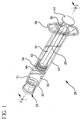
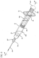
- FIG. 1 shows a syringe 20 according to the present invention generally comprising a barrel 22 and a plunger 24.
- the barrel 22 has a generally elongate body including an open proximal end 28 having finger grips 29, a distal end 30 having a distal wall 31 and an inside surface 32 defining a chamber 33 for retaining fluid.
- the distal end 30 further includes a tip 36 having a passageway 38 in fluid communication with the chamber.
- the distal end of barrel 22 preferably, but not necessarily includes a locking luer type collar 40 concentrically surrounding tip 36.
- the inside surface of the collar includes at least one thread 43.
- a cannula 26 includes a proximal end 42, a distal end 44 and a lumen 46 therethrough.
- the distal end may include a sharp tip or a blunt tip 48 as shown.
- the cannula may be connected directly to the tip of the syringe barrel to establish fluid communication between the lumen and the chamber.
- the cannula may be part of a needle assembly 27 including a hub 34 having an open proximal end 37 containing a cavity 41 and a distal end 39 attached to the proximal end of the cannula so that the lumen of the cannula is in fluid communication with the cavity.
- the cavity of the hub can be removably frictionally engaged to the tip of the barrel as illustrated in Figs. 2-3 .
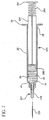
- Plunger 24 includes an elongate body portion 25, a proximal end 50 having a flange 51, and a distal end 52.
- a flexible base 53 extends axially from distal end 52 of the plunger 24.
- Base 53 has a diameter smaller than the diameter of the plunger 24 and may include threads.
- a stopper 54 is disposed on flexible base 53 at distal end 52 of the plunger, preferably via threading engagement.
- the flexible base 53 supports the stopper 54 at its center.
- Stopper 54 includes a plurality of ribs 56 on its outside diameter.
- the stopper 53 may be made of any material suitable for providing sealing characteristics while under compression.
- the stopper may be made of thermoplastic elastomers, natural rubber, synthetic rubber, silicon or thermoplastic materials.
- the base in this embodiment is preferably made of material which is more flexible than the stopper such as thermoplastic elastomers, natural rubber, synthetic rubber, polyurethane, silicone and the like.
- syringe 20 is connected to a hypodermic needle assembly and filled with flush solution using known methods.
- the flush solution may be any solution intended for flushing. It is preferred that the flush solution be selected from the group consisting of saline flush solution and heparin lock flush solution. These solutions are known in the art and readily available.
- An example of a saline flush solution is 0.9% Sodium Chloride USP.
- An example of a heparin lock flush solution is 0.9% Sodium Chloride with 100 USP units of Heparin Sodium per ml or 10 USP units of Heparin Sodium per ml.
- the syringe with needle assembly attached is used to pierce the pierceable septum or a blunt cannula may be inserted into a pre-split septum of a vial containing flush solution and the flush solution is drawn into the syringe barrel by pulling plunger rod flange 51 in the proximal direction while holding barrel 22, to draw fluid through the needle cannula into the fluid chamber 34.
- the syringe may be filled with flush solution during the manufacturing of the syringe via a sterile filling method.
- Such prefilled syringes may be supplied with a tip cap such as tip cap 23 releasably connected to tip 36 sealing passageway 38.
- the tip cap is formed of material selected from the group of thermoplastic materials and elastomeric materials such as natural and synthetic rubber and thermoplastic elastomers.
- I.V. set 64 comprises an I.V. site 65 which includes a housing 67 having a hollow interior 68 and a septum 69 at its proximal end.
- a catheter 70 having a conduit therethrough extends from the distal end of the housing.
- septum 69 is pre-slit for use with blunt cannula.
- the I.V. site may be a valve having structure for accepting the syringe barrel tip and being activated by the insertion of the tip to establish fluid communication with the catheter, such as the valve taught in U.S. Patent No. 6,171,287 .
- Blunt tip 48 of cannula 26 may be inserted through pre-split septum 69 of I.V. set 64.
- a sharp tip of a needle cannula may be used to pierce a septum that is not pre-split or the tip of the barrel may be engaged with a valve in the IV site.
- This establishes fluid communication between the interior 68 of the I.V. set and the chamber of the syringe barrel.
- the syringe barrel 22 is preferably held via finger grips 29. Pressure is then applied to flange 51 of the plunger, for example by a thumb, in the distal direction. This moves the plunger 24 having the stopper 54 on its distal end forcing the liquid such as flush solution 35 in the chamber 34 out of the chamber, through cannula 26 and into interior 68 of the I.V. set and then through catheter 70.
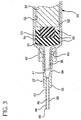
- Fig. 3 the position of the plunger and stopper at the completion of the flush procedure is shown.
- the flange 51 does not contact the proximal end of the barrel at the completion of the flush procedure. It is preferable, however, that the flange 51 of the plunger bottoms out on the proximal end of the plunger at the completion of the flush procedure.
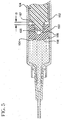
- FIG. 5 shows another embodiment of the invention.
- a distal end 152 of a plunger 124 is shown having a base 153 extending therefrom.
- a stopper 154 is disposed on the base.
- Base 153 includes treads 155 for threading engagement with the interior of the stopper.
- Stopper 154 includes one or more ribs 156 on its outer diameter.
- the stopper further includes an annular groove 157 concentrically surrounding base 153. As shown, the proximal end of the stopper 154 is displaced from the proximal end of the base by a distance denoted as D.
- the flush procedure is carried out as described above.
- stopper 154 contacts the distal end of the barrel.
- compressive force generated by this contact is translated to the proximal end of the stopper in the area of the annular groove which is, by virtue of its structure more flexible than the distal end of the stopper.
- the annular groove 157 and relief D act to create a structure wherein the proximal end of the stopper as it is connected to the base, is more flexible than the distal end of the stopper to absorb much of the compressive force.
- the distal end of stopper 154 and its ribs 156 are subject to less compression.
- the flexible proximal end of the stopper absorbs most of the compression forces so that the outside diameter near the face of the stopper does not compress. Since the distal end of stopper 154 does not compress as much as a more rigid stopper design, there is little or no reflux of liquid into the barrel 22.
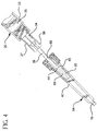
- FIGS. 6-9 show another embodiment of the present invention, where like elements are similarly numbered.
- the plunger 224 comprises a flexible or compressible portion 260 at its proximal end 250.
- the compressible portion 260 may be, for example a compressible spring such as a coil spring or flexible members. As shown, the compressible portion 260 comprises a compressible spring including a plurality of ribs 262.
- the sharp tip 248 of the cannula 226 may be inserted through a septum of an I.V. set.
- a blunt tip of a needle cannula may be used to pierce a pre-slit septum. This establishes fluid communication between the catheter of the I.V. set and the chamber 33 of the syringe barrel.
- the syringe barrel 22 is preferably held via finger grips 29. Pressure is then applied to the flange 251 of the plunger, for example by a thumb, in the distal direction. This moves the plunger 224 having the stopper 254 on its distal end forcing the liquid in the chamber 33 out of the chamber, through the cannula 226 and into the conduit of the I.V. set through the catheter.
- the distal end of the stopper contacts and presses against the distal wall of the barrel.
- the compressible portion 260 absorbs more of the compressive forces generated by this stopper contact rather than the stopper 254.
- stopper 254 does in fact compress, any relaxation that is caused by the compression of stopper 254 can be translated to and absorbed by the compressible portion 260.
Description
- The present invention relates to syringe assemblies and particularly to syringe assemblies for use in I.V. flush procedures.
- An I.V. catheter is a commonly used therapeutic device. Many patients, in accordance with their therapy, have an I.V. catheter connected to a vein ready for use in various procedures or in fluid communication with an I.V. system for infusing liquids and medication. Many I.V. sets have I.V. ports which are in fluid communication with a catheter and allow access for the purpose of injecting medication into the patient, and for use in flushing techniques to maintain catheter integrity. Healthcare facilities have flushing protocols which depend on the amount of time the catheter will remain in the patient and the type of catheter being used. For example, a peripherally inserted central catheter (PICC) is a long flexible catheter, which is typically inserted into the central venous system (optimally with the tip terminating in the superior vena cava) via the superficial veins of the antecubital fossa. PICC lines are designed for use when intermediate or long-term therapy is prescribed.
- These catheter lines must be periodically flushed with saline flush solution and/or heparin lock flush solution depending on the protocol. Among other things, flushing saline solution removes blood from the catheter and heparin helps prevent the formation of future blood clots. The most common I.V. ports are covered by pierceable septums or pre-slit septums and are known in the art and sometimes referred to as "PRN" from the Latin pro re nata meaning "as the need arises". The septum is preferably made of rubber or another elastomeric material which permits insertion of a sharp needle cannula in order to infuse fluids into or to withdraw fluids from the catheter. Upon withdrawal of the needle cannula the septum seals itself. Ports having pre-slit septums are used with blunt cannula. Typically, the blunt cannula is attached to a syringe and the syringe is moved to place a gentle pressure on the pre-slit septum which is forced open by the blunt cannula to establish fluid communication. Also, some I.V. sets have access valves which are responsive to the frusto-conically shaped tip of a syringe barrel for allowing fluid communication between the interior of the syringe and the catheter without the use of a cannula.
- Catheters are flushed using syringe assemblies filled with various fluids. In some cases, different fluids are injected sequentially in accordance with the protocol. For example, a saline solution followed by an anticoagulant such as heparin. The size of the syringe used to flush I.V. lines varies by various factors including the size and length of the catheter. Typically syringes of 1ml, 3ml, 5ml and 10ml volume are used.
- It is important in the flush procedure not to draw blood back into the catheter where it can clot and seal the catheter, commonly referred to as "reflux". In order to prevent blood reflux into the catheter the user is encouraged to maintain a positive pressure in the line during the flush procedure. This may involve slowly withdrawing the syringe and cannula from the I.V. port while still applying pressure to the syringe plunger rod during the flush procedure. When using a syringe with an elastomeric stopper, the stopper is often compressed when it contacts the distal end of the syringe barrel at the completion of the flush procedure. When a user relieves the pressure to the plunger after the flush procedure is completed, the stopper will expand back to its normal size drawing liquid from the catheter into the syringe barrel. This is undesirable, since it can cause blood to enter the catheter at the catheter distal end (reflux).
- Therefore there is a need for simple, straight forward easy-to-manufacture syringe assemblies which helps reduce or eliminate reflux of blood into the catheter during and after the flushing procedure has occurred without changing flush protocols and procedures.
- An I.V. syringe assembly of the type defined in the first part of claim 1 is disclosed in
US 3,669,111 A . This syringe assembly comprises a hypodermic syringe having a cylindrical barrel and a plunger. A resilient means is incorporated between the barrel and the plunger to provide and transmit a force to move said plunger axially in an outward direction for a limited distance. This structure does not have the effect of an anti-reflux means. It causes any liquid to flow back into the syringe upon cessation of pressure on the plunger. - An I.V. syringe assembly is disclosed in
DE 44 23 753 C1 . This syringe assembly comprises a barrel and a plunger, which is axially immovable in the barrel. The plunger comprises a generally tubular plunger rod and a stopper on its distal end. The tubular plunger rod is designed as an elastic spring element. It does not extend through the proximal opening of the syringe barrel but is supported on an inner flange extending inwardly from a barrel gripping plate. The elastic spring element allows the stopper to move proximally during a thermal extension of the substance contained in the barrel. -
US-A-4,340,051 discloses a device for application to a syringe. The device is mounted on the finger-engaging plate of a plunger rod extending through the proximal opening of a syringe barrel. The finger-engaging member is effective to soften the pressure transmitted from the user's finger and to provide an indication to the user when a predetermined pressure has been applied. - A further example of prior art I.V syringe assembly is given in
US 4 064 879 A . - It is an object of the invention to provide an I.V. syringe assembly, which helps reduce or eliminate reflux of blood into the catheter during and after the flushing procedure.
- The present invention is directed to a syringe for use in flush applications. The syringe reduces or eliminates compression of distal end of the stopper at the completion of the flush procedure thereby reducing or eliminating reflux of blood into the catheter. Compression of the stopper is eliminated, or greatly reduced, by the presence of a compressible or flexible portion disposed on the plunger to absorb the compression forces usually absorbed by the stopper. Since compression of the stopper is translated to a portion of the plunger, reflux is reduced or eliminated.
- An I.V. flush syringe assembly includes a barrel having an inside surface defining a chamber for retaining fluid, an open proximal end and a distal end including a distal wall with an elongate tip extending distally therefrom having a passageway therethrough in fluid communication with the chamber. A plunger including an elongate body portion having a proximal end, a distal end and a stopper is slidably positioned in fluid-tight engagement with the inside surface of barrel for drawing fluid into and driving fluid out of the chamber by movement of the stopper relative to the barrel. The elongate body portion of the plunger extends outwardly from the open proximal end of the barrel. The I.V. flush syringe includes anti-reflux means for minimizing stopper deflection when fluid has been delivered from the chamber and the stopper is in contact with the distal wall. Such anti-reflux means provides a portion of the stopper and/or plunger which is more flexible than the distat end of the stopper so that distally directed forces on the plunger will not cause distortion of the distal end of the stopper because anti-reflux structure between the distal end of the stopper and the proximal end of the plunger rod deflects in response to the force.
- The anti-reflux structure can include the stopper being supported by a flexible base at the distal end of the plunger wherein the base is more flexible than the stopper in response to proximally directed forces on the stopper.
- The anti-reflux structure may include a stopper having a recess in its proximal end and a flexible base extending distally from the plunger wherein the base is positioned at least partially in the recess of the stopper and the base is softer than the stopper and deflectable upon application of a proximally directed force on the stopper.
- The anti-reflux structure may include the stopper being connected to a base at the distal end of the plunger wherein the stopper is configured to be more flexible at its proximal end than at its distal end in response to proximally directed forces on the stopper.
- The anti-reflux means may include a resilient portion in the plunger between the proximal end and the distal end of the plunger wherein the resilient portion is more deflectable than the stopper and deflectable upon application of a proximally directed force on the stopper.
- A method of flushing a catheter of the present invention comprises the steps of providing a syringe assembly having an inside surface defining a chamber for retaining fluid, an open proximal end and a distal end including a distal wall with an elongate tip extending distally therefrom having a passageway therethrough in fluid communication with the chamber, a plunger including an elongate body portion having a proximal end, a distal end and a stopper slidably positioned in fluid-tight engagement with the inside surface of the barrel for drawing fluid into and driving fluid out of the chamber by movement of the stopper relative to the barrel, the elongate body portion extending outwardly from the open proximal end of the barrel, a quantity of flush solution in said chamber, and anti-reflux means for minimizing stopper deflection when the flush solution has been delivered from the chamber and the stopper is in contact with and pressed against the distal wall. The method further includes providing a catheter having a proximal end, a distal end and a passageway therethrough and a housing having a hollow interior in fluid communication with the passageway, the housing having an access valve capable of engaging the elongate tip of the barrel for allowing fluid communication with the hollow interior of the housing. The method further includes the steps of placing the distal end of the catheter in a blood vessel; engaging the elongate tip of the barrel with the access valve so that the passageway in the tip is in fluid communication with the hollow interior of the housing; applying force to the plunger to move the plunger in a distal direction with respect to the barrel so that the flush solution in the chamber flows through the passageway into the hollow chamber of the housing and through the passageway of the catheter; continuing to apply force to the plunger until the stopper contacts and presses against the distal wall of the barrel; and disengaging the barrel from the access valve.
- An alternative method may include the step of attaching a needle assembly to the elongate tip of the barrel. The needle assembly includes a cannula having a proximal end, a distal end and a lumen therethrough and a hub having an open proximal end containing a cavity and a distal end attached to the proximal end of the cannula so that the lumen is in fluid communication with the cavity. The attachment of the needle assembly to the barrel is through frictional engagement between the cavity in the hub and the elongate tip. This alternative method is used with a catheter having a proximal end, a distal end and a passageway therethrough and a housing having a hollow interior connected to the catheter and in fluid communication with the passageway of the catheter. The housing further includes a septum for allowing fluid communication with the hollow interior. Fluid communication is established by forcing the distal end of the cannula through the septum so that the lumen of the cannula is in fluid communication with the hollow interior of the housing. Also, the cannula may be permanently attached to the barrel tip with or without the use of a hub.
-
-
FIG. 1 is a perspective view of a syringe assembly according to one embodiment of the invention. -
FIG. 2 is a partially cross-sectioned perspective view of the syringe assembly ofFIG. 1 with a needle assembly attached. -
FIG. 3 is an enlarged partial cross-sectional side elevation view of the distal end of the syringe assembly ofFIG. 2 . -
FIG. 4 is a side-elevational view illustrating the syringe assembly in use with a catheter injection site. -
FIG. 5 is a cross sectional side elevation view of the distal end of a plunger and stopper according to another embodiment of the invention -
FIG. 6 is a perspective view of a syringe assembly according to another embodiment of the invention. -
FIG. 7 is partially cross-sectioned perspective view of the syringe assembly ofFIG. 6 . -
FIG. 8 is a cross sectional side elevation view of the syringe assembly ofFIG. 6 . -
FIG. 9 is an enlarged cross-sectional view of the proximal end of the syringe assembly ofFIG. 8 . -
FIG. 1 shows asyringe 20 according to the present invention generally comprising abarrel 22 and aplunger 24. Thebarrel 22 has a generally elongate body including an openproximal end 28 having finger grips 29, adistal end 30 having adistal wall 31 and aninside surface 32 defining achamber 33 for retaining fluid. Thedistal end 30 further includes atip 36 having a passageway 38 in fluid communication with the chamber. The distal end ofbarrel 22 preferably, but not necessarily includes a lockingluer type collar 40 concentrically surroundingtip 36. The inside surface of the collar includes at least onethread 43. Acannula 26 includes aproximal end 42, adistal end 44 and alumen 46 therethrough. The distal end may include a sharp tip or ablunt tip 48 as shown. The cannula may be connected directly to the tip of the syringe barrel to establish fluid communication between the lumen and the chamber. Also, the cannula may be part of aneedle assembly 27 including ahub 34 having an open proximal end 37 containing acavity 41 and adistal end 39 attached to the proximal end of the cannula so that the lumen of the cannula is in fluid communication with the cavity. The cavity of the hub can be removably frictionally engaged to the tip of the barrel as illustrated inFigs. 2-3 . -
Plunger 24 includes anelongate body portion 25, aproximal end 50 having aflange 51, and adistal end 52. Aflexible base 53 extends axially fromdistal end 52 of theplunger 24.Base 53 has a diameter smaller than the diameter of theplunger 24 and may include threads. - A
stopper 54 is disposed onflexible base 53 atdistal end 52 of the plunger, preferably via threading engagement. Thus, theflexible base 53 supports thestopper 54 at its center.Stopper 54 includes a plurality ofribs 56 on its outside diameter. Thestopper 53 may be made of any material suitable for providing sealing characteristics while under compression. For example, the stopper may be made of thermoplastic elastomers, natural rubber, synthetic rubber, silicon or thermoplastic materials. The base in this embodiment is preferably made of material which is more flexible than the stopper such as thermoplastic elastomers, natural rubber, synthetic rubber, polyurethane, silicone and the like. - In operation,
syringe 20 is connected to a hypodermic needle assembly and filled with flush solution using known methods. The flush solution may be any solution intended for flushing. It is preferred that the flush solution be selected from the group consisting of saline flush solution and heparin lock flush solution. These solutions are known in the art and readily available. An example of a saline flush solution is 0.9% Sodium Chloride USP. An example of a heparin lock flush solution is 0.9% Sodium Chloride with 100 USP units of Heparin Sodium per ml or 10 USP units of Heparin Sodium per ml. The syringe with needle assembly attached is used to pierce the pierceable septum or a blunt cannula may be inserted into a pre-split septum of a vial containing flush solution and the flush solution is drawn into the syringe barrel by pullingplunger rod flange 51 in the proximal direction while holdingbarrel 22, to draw fluid through the needle cannula into thefluid chamber 34. - Alternatively, the syringe may be filled with flush solution during the manufacturing of the syringe via a sterile filling method. Such prefilled syringes may be supplied with a tip cap such as
tip cap 23 releasably connected to tip 36 sealing passageway 38. It is preferred that the tip cap is formed of material selected from the group of thermoplastic materials and elastomeric materials such as natural and synthetic rubber and thermoplastic elastomers. - The syringe is now ready for use in flushing a catheter of an I.V. set. I.V. sets can be very complicated and may include multiple injection ports, a valve and/or other components. For the purpose of illustrating the present invention a simplified I.V. set 64 is illustrated in
Fig. 4 . I.V. set 64 comprises an I.V.site 65 which includes ahousing 67 having ahollow interior 68 and aseptum 69 at its proximal end. Acatheter 70 having a conduit therethrough extends from the distal end of the housing. For this I.V. setseptum 69 is pre-slit for use with blunt cannula. The I.V. site may be a valve having structure for accepting the syringe barrel tip and being activated by the insertion of the tip to establish fluid communication with the catheter, such as the valve taught inU.S. Patent No. 6,171,287 . -
Blunt tip 48 ofcannula 26 may be inserted throughpre-split septum 69 of I.V. set 64. Alternatively, a sharp tip of a needle cannula may be used to pierce a septum that is not pre-split or the tip of the barrel may be engaged with a valve in the IV site. This establishes fluid communication between the interior 68 of the I.V. set and the chamber of the syringe barrel. Thesyringe barrel 22 is preferably held via finger grips 29. Pressure is then applied toflange 51 of the plunger, for example by a thumb, in the distal direction. This moves theplunger 24 having thestopper 54 on its distal end forcing the liquid such asflush solution 35 in thechamber 34 out of the chamber, throughcannula 26 and intointerior 68 of the I.V. set and then throughcatheter 70. - Referring to
Fig. 3 the position of the plunger and stopper at the completion of the flush procedure is shown. As shown, theflange 51 does not contact the proximal end of the barrel at the completion of the flush procedure. It is preferable, however, that theflange 51 of the plunger bottoms out on the proximal end of the plunger at the completion of the flush procedure. When the distal face of thestopper 54 contacts thedistal end 30 of thebarrel 22, compressive force generated by this contact is translated to theflexible base 53. Thus, compression of thestopper 54 and itsribs 56 is reduced. Theflexible base 53, therefore, absorbs compressive forces so that compression of the stopper face and the outside diameter of the stopper is reduced. Since thestopper 54 does not compress substantially, there is little or no reflux of liquid into the catheter that typically results from the expansion of the stopper after compression. -
FIG. 5 shows another embodiment of the invention. Adistal end 152 of aplunger 124 is shown having a base 153 extending therefrom. Astopper 154 is disposed on the base.Base 153 includestreads 155 for threading engagement with the interior of the stopper.Stopper 154 includes one ormore ribs 156 on its outer diameter. The stopper further includes anannular groove 157 concentrically surroundingbase 153. As shown, the proximal end of thestopper 154 is displaced from the proximal end of the base by a distance denoted as D. - In operation, the flush procedure is carried out as described above. At the completion of the flush procedure,
stopper 154 contacts the distal end of the barrel. Whendistal face 158 of the stopper contacts the distal wall of barrel, compressive force generated by this contact is translated to the proximal end of the stopper in the area of the annular groove which is, by virtue of its structure more flexible than the distal end of the stopper. Theannular groove 157 and relief D act to create a structure wherein the proximal end of the stopper as it is connected to the base, is more flexible than the distal end of the stopper to absorb much of the compressive force. Thus, the distal end ofstopper 154 and itsribs 156 are subject to less compression. The flexible proximal end of the stopper absorbs most of the compression forces so that the outside diameter near the face of the stopper does not compress. Since the distal end ofstopper 154 does not compress as much as a more rigid stopper design, there is little or no reflux of liquid into thebarrel 22. -
FIGS. 6-9 show another embodiment of the present invention, where like elements are similarly numbered. In this embodiment of the invention, theplunger 224 comprises a flexible orcompressible portion 260 at its proximal end 250. Thecompressible portion 260 may be, for example a compressible spring such as a coil spring or flexible members. As shown, thecompressible portion 260 comprises a compressible spring including a plurality of ribs 262. - In operation, after the syringe barrel has been filled with flush solution as discussed above, the sharp tip 248 of the
cannula 226 may be inserted through a septum of an I.V. set. Alternatively, a blunt tip of a needle cannula may be used to pierce a pre-slit septum. This establishes fluid communication between the catheter of the I.V. set and thechamber 33 of the syringe barrel. Thesyringe barrel 22 is preferably held via finger grips 29. Pressure is then applied to theflange 251 of the plunger, for example by a thumb, in the distal direction. This moves theplunger 224 having thestopper 254 on its distal end forcing the liquid in thechamber 33 out of the chamber, through thecannula 226 and into the conduit of the I.V. set through the catheter. - At the completion of the flush procedure, the distal end of the stopper contacts and presses against the distal wall of the barrel. The
compressible portion 260 absorbs more of the compressive forces generated by this stopper contact rather than thestopper 254. In addition, ifstopper 254 does in fact compress, any relaxation that is caused by the compression ofstopper 254 can be translated to and absorbed by thecompressible portion 260. - Although the invention herein has been described with reference to particular embodiments, it is to be understood that these embodiments are merely illustrative of the principles and applications of the present invention. It is therefore to be understood that numerous modifications may be made to the illustrative embodiments and that other arrangements may be devised without departing from the scope of the present invention as disclosed.
Claims (9)
- An I.V. syringe assembly comprising:a barrel (22) having an inside surface (32) defining a chamber (33) for retaining flush fluid, an open proximal end (28) and a distal end (30) including a distal wall (31) with an elongate tip (36) extending distally therefrom having a passageway therethrough in fluid communication with said chamber; anda plunger (24) including an elongate body portion (25) extending outwardly through said open proximal end (28) of said barrel and having a proximal end (50), a distal end (52) and a stopper (54) made of a material suitable of providing sealing characteristics while under compression and being slidably positioned in fluid-tight engagement with said inside surface (32) of said barrel for drawing fluid into and driving fluid out of said chamber (33) by movement of said stopper relative to said barrel,characterized in thatthe syringe assembly is an I.V. flush syringe assembly adapted for flushing a catheter (70) of an I.V. set (64), andthe distal end of the plunger (24) includes a flexible base extending axially therefrom, said flexible base of the plunger being made of a material more flexible than said stopper material in response to proximally directed forces; wherein deflection of said stopper is minimized when fluid has been delivered from said chamber and said stopper is in contact with said distal wall (31).
- The syringe assembly of claim 1 wherein said anti-reflux means includes said stopper (54) being supported by a flexible base (53) at said distal end (52) of said plunger (24), said base being more flexible than said stopper (54) in response to proximally directed forces on said stopper.
- The syringe assembly of claim 1 wherein said anti-reflux means includes said stopper (154) being connected to a base (156) at said distal end of said plunger (124), said stopper being configured to be more flexible at its proximal end than at its distal end in response to proximally directed forces on said stopper.
- The syringe assembly of claim 1 wherein said anti-reflux means includes said stopper (54) having a recess in its proximal end and a flexible base (53) extending distally from said plunger, said base positioned at least partially in said recess, said base being softer than said stopper and deflectable upon the application of a proximally directed force on said stopper.
- The syringe assembly of claim 1 wherein said anti-reflux means includes a resilient portion (260) in said plunger between said proximal end and said distal end of said plunger, said resilient portion being more deflectable than said stopper and deflectable upon the application of a proximally directed force on said stopper.
- The syringe assembly of claim 1 including flush solution in said chamber (33).
- The syringe assembly of claim 6 further including a tip cap (23) releasably connected to said tip (36) of said syringe barrel for sealing said passageway.
- The syringe assembly of claim 4 wherein said flexible base (53) is made of material selected from the list consisting of natural rubber, synthetic rubber, thermoplastic elastomers and combinations thereof.
- The syringe assembly of claim 5 wherein said resilient portion (260) in said plunger includes a spring.
Priority Applications (2)
| Application Number | Priority Date | Filing Date | Title |
|---|---|---|---|
| EP18166940.9A EP3366340B1 (en) | 2002-10-11 | 2003-09-23 | Flush syringe having compressible plunger |
| EP16154058.8A EP3100755B1 (en) | 2002-10-11 | 2003-09-23 | Flush syringe having compressible plunger |
Applications Claiming Priority (3)
| Application Number | Priority Date | Filing Date | Title |
|---|---|---|---|
| US41795402P | 2002-10-11 | 2002-10-11 | |
| US417954P | 2002-10-11 | ||
| PCT/US2003/029725 WO2004033006A2 (en) | 2002-10-11 | 2003-09-23 | Flush syringe having compressible plunger |
Related Child Applications (3)
| Application Number | Title | Priority Date | Filing Date |
|---|---|---|---|
| EP18166940.9A Division EP3366340B1 (en) | 2002-10-11 | 2003-09-23 | Flush syringe having compressible plunger |
| EP16154058.8A Division-Into EP3100755B1 (en) | 2002-10-11 | 2003-09-23 | Flush syringe having compressible plunger |
| EP16154058.8A Division EP3100755B1 (en) | 2002-10-11 | 2003-09-23 | Flush syringe having compressible plunger |
Publications (2)
| Publication Number | Publication Date |
|---|---|
| EP1549367A2 EP1549367A2 (en) | 2005-07-06 |
| EP1549367B1 true EP1549367B1 (en) | 2016-04-06 |
Family
ID=32094124
Family Applications (3)
| Application Number | Title | Priority Date | Filing Date |
|---|---|---|---|
| EP18166940.9A Expired - Lifetime EP3366340B1 (en) | 2002-10-11 | 2003-09-23 | Flush syringe having compressible plunger |
| EP16154058.8A Expired - Lifetime EP3100755B1 (en) | 2002-10-11 | 2003-09-23 | Flush syringe having compressible plunger |
| EP03759362.1A Expired - Lifetime EP1549367B1 (en) | 2002-10-11 | 2003-09-23 | Flush syringe having compressible plunger |
Family Applications Before (2)
| Application Number | Title | Priority Date | Filing Date |
|---|---|---|---|
| EP18166940.9A Expired - Lifetime EP3366340B1 (en) | 2002-10-11 | 2003-09-23 | Flush syringe having compressible plunger |
| EP16154058.8A Expired - Lifetime EP3100755B1 (en) | 2002-10-11 | 2003-09-23 | Flush syringe having compressible plunger |
Country Status (8)
| Country | Link |
|---|---|
| US (4) | US20060100591A1 (en) |
| EP (3) | EP3366340B1 (en) |
| JP (1) | JP4856873B2 (en) |
| AU (2) | AU2003275091A1 (en) |
| CA (3) | CA2922063C (en) |
| ES (3) | ES2803379T3 (en) |
| NO (1) | NO336816B1 (en) |
| WO (1) | WO2004033006A2 (en) |
Families Citing this family (61)
| Publication number | Priority date | Publication date | Assignee | Title |
|---|---|---|---|---|
| US8202257B2 (en) | 1998-07-29 | 2012-06-19 | Becton, Dickinson And Company | Splatter prevention mechanism for a syringe |
| JP4681795B2 (en) | 2001-05-18 | 2011-05-11 | デカ・プロダクツ・リミテッド・パートナーシップ | Fluid pump infusion set |
| US8034026B2 (en) | 2001-05-18 | 2011-10-11 | Deka Products Limited Partnership | Infusion pump assembly |
| EP3366340B1 (en) * | 2002-10-11 | 2020-04-22 | Becton, Dickinson and Company | Flush syringe having compressible plunger |
| US7534233B2 (en) * | 2003-09-23 | 2009-05-19 | Becton, Dickson And Company | Flush syringe having anti-reflux features |
| US7331942B2 (en) * | 2003-09-23 | 2008-02-19 | Becton, Dickinson And Company | Flush syringe having anti-reflux stopper |
| US20050070874A1 (en) * | 2003-09-30 | 2005-03-31 | Hikaru Matsuda | System and method for injecting liquid drug containing biological material |
| US9522237B2 (en) * | 2005-01-07 | 2016-12-20 | Becton, Dickinson And Company | Positive displacement flush syringe |
| US8936577B2 (en) | 2005-05-02 | 2015-01-20 | Shi Zi Technology, Ltd. | Methods and devices for autoflush syringes |
| US8529517B2 (en) * | 2005-05-02 | 2013-09-10 | Shi Zi Technology, Ltd. | Autoflush syringe |
| US8075533B2 (en) | 2005-05-02 | 2011-12-13 | Preventiv, Inc. | Autoflush syringe |
| US8852164B2 (en) | 2006-02-09 | 2014-10-07 | Deka Products Limited Partnership | Method and system for shape-memory alloy wire control |
| US11478623B2 (en) | 2006-02-09 | 2022-10-25 | Deka Products Limited Partnership | Infusion pump assembly |
| DE602007013723D1 (en) | 2006-02-09 | 2011-05-19 | Deka Products Lp | SYSTEMS FOR DISPENSING FLUIDS IN PATCH SIZE |
| US11364335B2 (en) | 2006-02-09 | 2022-06-21 | Deka Products Limited Partnership | Apparatus, system and method for fluid delivery |
| US11497846B2 (en) | 2006-02-09 | 2022-11-15 | Deka Products Limited Partnership | Patch-sized fluid delivery systems and methods |
| FR2905873B1 (en) * | 2006-09-20 | 2008-11-14 | Becton Dickinson France Soc Pa | INJECTION DEVICE PREVENTING PISTON RELEASE DURING DEPLOYMENT OF THE SAFETY SYSTEM |
| US8740856B2 (en) * | 2007-06-04 | 2014-06-03 | Becton, Dickinson And Company | Stoppers used in pre-filled syringes |
| CA2639729A1 (en) * | 2007-09-27 | 2009-03-27 | Tyco Healthcare Group Lp | Multiple stage fluid delivery device and method of use |
| US8881774B2 (en) | 2007-12-31 | 2014-11-11 | Deka Research & Development Corp. | Apparatus, system and method for fluid delivery |
| US10188787B2 (en) | 2007-12-31 | 2019-01-29 | Deka Products Limited Partnership | Apparatus, system and method for fluid delivery |
| US9456955B2 (en) | 2007-12-31 | 2016-10-04 | Deka Products Limited Partnership | Apparatus, system and method for fluid delivery |
| US8900188B2 (en) | 2007-12-31 | 2014-12-02 | Deka Products Limited Partnership | Split ring resonator antenna adapted for use in wirelessly controlled medical device |
| WO2009088956A2 (en) | 2007-12-31 | 2009-07-16 | Deka Products Limited Partnership | Infusion pump assembly |
| US10080704B2 (en) | 2007-12-31 | 2018-09-25 | Deka Products Limited Partnership | Apparatus, system and method for fluid delivery |
| CA2919786C (en) | 2007-12-31 | 2019-10-22 | Deka Products Limited Partnership | Infusion pump assembly |
| JP5284720B2 (en) * | 2008-08-07 | 2013-09-11 | 株式会社トクヤマデンタル | Flowable member pouring device and flowable member pouring method |
| WO2010031059A2 (en) | 2008-09-15 | 2010-03-18 | Deka Products Limited Partnership | Systems and methods for fluid delivery |
| US8708376B2 (en) | 2008-10-10 | 2014-04-29 | Deka Products Limited Partnership | Medium connector |
| US8066672B2 (en) | 2008-10-10 | 2011-11-29 | Deka Products Limited Partnership | Infusion pump assembly with a backup power supply |
| US8262616B2 (en) | 2008-10-10 | 2012-09-11 | Deka Products Limited Partnership | Infusion pump assembly |
| US8016789B2 (en) | 2008-10-10 | 2011-09-13 | Deka Products Limited Partnership | Pump assembly with a removable cover assembly |
| US8223028B2 (en) | 2008-10-10 | 2012-07-17 | Deka Products Limited Partnership | Occlusion detection system and method |
| US8267892B2 (en) | 2008-10-10 | 2012-09-18 | Deka Products Limited Partnership | Multi-language / multi-processor infusion pump assembly |
| US9180245B2 (en) | 2008-10-10 | 2015-11-10 | Deka Products Limited Partnership | System and method for administering an infusible fluid |
| IN2012DN00344A (en) * | 2009-07-10 | 2015-05-08 | Becton Dickinson Co | |
| WO2011008966A2 (en) | 2009-07-15 | 2011-01-20 | Deka Products Limited Partnership | Apparatus, systems and methods for an infusion pump assembly |
| US10682507B2 (en) | 2009-10-29 | 2020-06-16 | One Iv Solutions, Llc | Catheter extension with integrated circumferentially sealing securement dressing |
| AU2010319924B2 (en) * | 2009-10-29 | 2014-03-06 | Robert E. Helm | Sealed sterile catheter dressings |
| SE534343C2 (en) * | 2010-01-19 | 2011-07-19 | St Jude Medical Systems Ab | Injektionstrycksättare |
| US8344078B2 (en) | 2010-05-21 | 2013-01-01 | Chevron Phillips Chemical Company Lp | Continuous take off technique and pressure control of polymerization reactors |
| WO2012106088A2 (en) | 2011-01-31 | 2012-08-09 | Helm Robert E Jr | Snap-seal sterile intravascular catheter-dressing system |
| CN102363056B (en) | 2011-08-01 | 2013-06-05 | 上海萌黎国际贸易有限公司 | Needle head protection device and safety needle component |
| WO2013040154A1 (en) * | 2011-09-15 | 2013-03-21 | Helm Robert E Jr | Catheter-dressing systems with integrated flushing mechanisms |
| WO2013134519A2 (en) | 2012-03-07 | 2013-09-12 | Deka Products Limited Partnership | Apparatus, system and method for fluid delivery |
| CN103463713B (en) * | 2012-06-06 | 2019-09-13 | 千禧光医疗科技(上海)有限公司 | Disposable syringe and push rod for disposable syringe |
| EP3016629B1 (en) | 2013-07-03 | 2023-12-20 | DEKA Products Limited Partnership | Apparatus and system for fluid delivery |
| WO2015007815A1 (en) * | 2013-07-17 | 2015-01-22 | Sanofi | Driving configuration for a drug delivery device |
| US20170021108A1 (en) * | 2014-04-02 | 2017-01-26 | Aptar Stelmi Sas | Anti-reflux syringe assembly |
| US10857301B2 (en) | 2016-09-20 | 2020-12-08 | Endospace Corporation | Syringe with position locking plunger |
| US20180099082A1 (en) * | 2016-10-07 | 2018-04-12 | Sandra Macasieb | Intravenous Flushing System |
| USD804651S1 (en) | 2017-01-10 | 2017-12-05 | Howard Loonan | Syringe |
| US10029230B1 (en) | 2017-01-24 | 2018-07-24 | Chevron Phillips Chemical Company Lp | Flow in a slurry loop reactor |
| US11679177B2 (en) | 2017-08-08 | 2023-06-20 | Baxter International Inc. | Polymeric compositions, delivery devices, and methods |
| US11083847B2 (en) | 2018-01-26 | 2021-08-10 | Becton, Dickinson And Company | Flush syringe with flip cap |
| JP7321535B2 (en) | 2018-03-27 | 2023-08-07 | インイェクト・グループ・エー/エス | Stopper with low force for use in injectors |
| WO2019209963A1 (en) | 2018-04-24 | 2019-10-31 | Deka Products Limited Partnership | Apparatus and system for fluid delivery |
| USD914872S1 (en) * | 2019-07-12 | 2021-03-30 | Retractable Technologies, Inc. | Syringe barrel |
| USD914873S1 (en) * | 2019-07-12 | 2021-03-30 | Retractable Technologies, Inc | Syringe barrel |
| US20230233374A1 (en) * | 2020-06-11 | 2023-07-27 | Aescula Tech, Inc. | Device for Controlled Injection Across a Variety of Material Properties |
| GB2603181A (en) * | 2021-01-29 | 2022-08-03 | Naturalskn Ltd | A thumb tab for a syringe |
Citations (1)
| Publication number | Priority date | Publication date | Assignee | Title |
|---|---|---|---|---|
| US4064879A (en) * | 1976-04-06 | 1977-12-27 | Metatech Corporation | Pressure-indicating syringe |
Family Cites Families (62)
| Publication number | Priority date | Publication date | Assignee | Title |
|---|---|---|---|---|
| BE472756A (en) * | 1946-04-26 | |||
| US2592381A (en) * | 1949-10-13 | 1952-04-08 | Premo Pharmaceutical Lab Inc | Hypodermic syringe |
| US2886034A (en) * | 1955-04-11 | 1959-05-12 | Charles V Robinson | Plungers for hypodermic syringes and the like |
| US2832340A (en) * | 1957-03-26 | 1958-04-29 | American Home Prod | Syringe push rod |
| US2907330A (en) * | 1958-06-10 | 1959-10-06 | Ernest S V Laub | Compressible plunger for hypodermic syringes |
| FR1288146A (en) * | 1961-02-08 | 1962-03-24 | New double-acting seal which can be used in particular for plastic syringes | |
| US3176595A (en) * | 1963-05-22 | 1965-04-06 | Galland Henning Mfg Company | Plastic piston assembly |
| US3270743A (en) * | 1963-05-29 | 1966-09-06 | Leeming Miles Pharmaccuticals | Hypodermic injection syringe |
| US3331538A (en) * | 1963-07-17 | 1967-07-18 | Roehr Products Company Inc | Syringe |
| US3303846A (en) * | 1963-10-08 | 1967-02-14 | Functional Container Corp | Mixing syringe having separate compartments for incompatible medicaments |
| US3618603A (en) * | 1969-01-29 | 1971-11-09 | Levenson M F | Syringe |
| US3669111A (en) * | 1970-05-20 | 1972-06-13 | Ben B Dubner | Automatic retracting hypodermic syringe |
| JPS5213701Y2 (en) * | 1973-12-03 | 1977-03-28 | ||
| US3889673A (en) * | 1974-01-02 | 1975-06-17 | Survival Technology | Tip assembly for syringes |
| US4212309A (en) * | 1978-09-28 | 1980-07-15 | Ballard Medical Products, Inc. | Blood gas sampler |
| US4340051A (en) * | 1981-01-12 | 1982-07-20 | Saul Leibinsohn | Finger-pressure cushioning and indicating device, and syringe including same |
| HU189198B (en) * | 1982-12-10 | 1986-06-30 | Adorjan,Andras,Hu | Plastic syringe for single use as well as plastic piston particularly for plastic syringes |
| US4543093A (en) * | 1982-12-20 | 1985-09-24 | Becton, Dickinson And Company | Variable sealing pressure plunger rod assembly |
| US4664128A (en) * | 1983-12-16 | 1987-05-12 | Peter F. Lee, Inc | Single-hand controlled aspiration device |
| US4713060A (en) * | 1986-06-20 | 1987-12-15 | Becton, Dickinson And Company | Syringe assembly |
| JPH0747045B2 (en) * | 1986-10-15 | 1995-05-24 | 株式会社大協精工 | Stacked syringe stopper |
| DE3709783C1 (en) * | 1987-03-25 | 1988-04-14 | Blendax Werke Schneider Co | Dosing syringe |
| US4865583A (en) * | 1987-05-04 | 1989-09-12 | Tu Ho C | Combination blood sampling and intravenous infusion apparatus and method |
| US4781684A (en) * | 1987-09-03 | 1988-11-01 | Trenner Lewis E | Single use disposable hypodermic syringe |
| US4950240A (en) * | 1988-10-04 | 1990-08-21 | Greenwood Eugene C | Hypodermic syringe for single use |
| US5201709A (en) * | 1989-06-16 | 1993-04-13 | Capra Nicholas G | Single use, self destructing disposable syringe |
| IL93045A (en) * | 1990-01-12 | 1995-01-24 | Rosenberg Lior | Vacuum device particularly useful for draining wounds |
| US5006114A (en) * | 1990-04-20 | 1991-04-09 | Rogers Bobby E | Medical valve assembly |
| US5106372A (en) * | 1991-05-03 | 1992-04-21 | Sherwood Medical Company | Single use syringe |
| US5147333A (en) * | 1991-05-13 | 1992-09-15 | Burron Medical Inc. | Needleless injection port with automatic backcheck valve |
| US5259840A (en) * | 1991-09-03 | 1993-11-09 | Boris Craig R | Locking syringe |
| US5246423A (en) * | 1991-11-01 | 1993-09-21 | Farkas Paul J | Remote cannula removal hypodermic syringe |
| US5215536A (en) * | 1991-11-13 | 1993-06-01 | Merit Medical Systems, Inc. | Self-locking control syringe |
| US5314416A (en) * | 1992-06-22 | 1994-05-24 | Sherwood Medical Company | Low friction syring assembly |
| US5370620A (en) * | 1992-12-28 | 1994-12-06 | Shonfeld; David | Single use hypodermic syringe |
| US5509433A (en) * | 1993-10-13 | 1996-04-23 | Paradis; Joseph R. | Control of fluid flow |
| US5395345A (en) * | 1994-01-27 | 1995-03-07 | The Kendall Company | Aspirating syringe |
| US5413563A (en) * | 1994-05-06 | 1995-05-09 | Sterling Winthrop Inc. | Pre-filled syringe having a plunger, plunger insert and plunger rod |
| US5820601A (en) | 1994-06-20 | 1998-10-13 | Critical Device Corporation | Needleless injection site |
| JP2584722B2 (en) * | 1994-06-21 | 1997-02-26 | 株式会社崇洋堂 | Syringe |
| DE4423753C1 (en) * | 1994-06-27 | 1996-02-01 | Schering Ag | Multi-part syringe with a glass cylinder |
| US5688252A (en) * | 1994-09-30 | 1997-11-18 | Takeda Chemical Industries, Ltd. | Syringe |
| US5735825A (en) * | 1996-03-22 | 1998-04-07 | Merit Medical Systems, Inc. | Syringe plunger tip |
| US5865798A (en) | 1996-06-28 | 1999-02-02 | Becton Dickinson France, S.A. | Stopper assembly having bypass features for use in a multi-chamber syringe barrel |
| US5873861A (en) | 1996-11-12 | 1999-02-23 | Medrad, Inc. | Plunger systems |
| CA2285330C (en) * | 1997-03-29 | 2005-06-07 | Ji Hoon Park | Continuous injecting apparatus |
| US6053894A (en) | 1997-08-04 | 2000-04-25 | Shadd, Jr.; Daniel L. | Hypodermic syringe |
| US5807374A (en) | 1997-08-14 | 1998-09-15 | Becton, Dickinson And Company | Syringe filling and delivery device |
| US6004300A (en) * | 1997-08-28 | 1999-12-21 | Butcher; Robert M | Composite hypodermic syringe piston |
| US6361524B1 (en) * | 1998-04-14 | 2002-03-26 | Becton, Dickinson And Company | Syringe assembly |
| CA2236049C (en) * | 1998-04-27 | 2006-07-25 | Computer Controlled Syringe Inc. | Syringe with detachable syringe barrel |
| DE69940669D1 (en) | 1998-05-29 | 2009-05-14 | Lawrence A Lynn | Luer adapter and method for fluid transfer |
| JP4558130B2 (en) * | 2000-03-17 | 2010-10-06 | 株式会社トップ | Syringe |
| AU2001274548A1 (en) | 2000-06-19 | 2002-01-02 | Terumo Kabushiki Kaisha | Syringe |
| US20050010235A1 (en) * | 2003-07-09 | 2005-01-13 | Vandusseldorp Gregg A. | Surgical device |
| JP4602579B2 (en) * | 2001-03-15 | 2010-12-22 | テルモ株式会社 | Syringe |
| US6579263B1 (en) * | 2002-01-11 | 2003-06-17 | Milton Chernack | Method and apparatus for the delivery of contrast fluid to a patient |
| US6830564B2 (en) * | 2002-01-24 | 2004-12-14 | Robin Scott Gray | Syringe and method of using |
| EP3366340B1 (en) * | 2002-10-11 | 2020-04-22 | Becton, Dickinson and Company | Flush syringe having compressible plunger |
| US20040127859A1 (en) * | 2002-12-26 | 2004-07-01 | Ward Michael Terrance | Anti-reflux syringe |
| US8062254B2 (en) * | 2008-01-08 | 2011-11-22 | MacLean, LLC | Spring driven adjustable oral syringe |
| IN2012DN00344A (en) * | 2009-07-10 | 2015-05-08 | Becton Dickinson Co |
-
2003
- 2003-09-23 EP EP18166940.9A patent/EP3366340B1/en not_active Expired - Lifetime
- 2003-09-23 WO PCT/US2003/029725 patent/WO2004033006A2/en active Application Filing
- 2003-09-23 CA CA2922063A patent/CA2922063C/en not_active Expired - Lifetime
- 2003-09-23 ES ES18166940T patent/ES2803379T3/en not_active Expired - Lifetime
- 2003-09-23 AU AU2003275091A patent/AU2003275091A1/en not_active Abandoned
- 2003-09-23 ES ES03759362.1T patent/ES2577277T3/en not_active Expired - Lifetime
- 2003-09-23 US US10/530,831 patent/US20060100591A1/en not_active Abandoned
- 2003-09-23 JP JP2004543328A patent/JP4856873B2/en not_active Expired - Lifetime
- 2003-09-23 EP EP16154058.8A patent/EP3100755B1/en not_active Expired - Lifetime
- 2003-09-23 EP EP03759362.1A patent/EP1549367B1/en not_active Expired - Lifetime
- 2003-09-23 CA CA2501933A patent/CA2501933C/en not_active Expired - Lifetime
- 2003-09-23 CA CA2812002A patent/CA2812002C/en not_active Expired - Lifetime
- 2003-09-23 ES ES16154058.8T patent/ES2683877T3/en not_active Expired - Lifetime
-
2005
- 2005-05-10 NO NO20052294A patent/NO336816B1/en not_active IP Right Cessation
-
2008
- 2008-05-08 US US12/117,257 patent/US8512298B2/en active Active
-
2009
- 2009-08-25 AU AU2009212793A patent/AU2009212793B2/en not_active Expired
-
2013
- 2013-03-19 US US13/847,157 patent/US8882724B2/en not_active Expired - Lifetime
-
2014
- 2014-10-13 US US14/512,792 patent/US9333301B2/en not_active Expired - Lifetime
Patent Citations (1)
| Publication number | Priority date | Publication date | Assignee | Title |
|---|---|---|---|---|
| US4064879A (en) * | 1976-04-06 | 1977-12-27 | Metatech Corporation | Pressure-indicating syringe |
Also Published As
| Publication number | Publication date |
|---|---|
| US9333301B2 (en) | 2016-05-10 |
| US20130218097A1 (en) | 2013-08-22 |
| CA2922063C (en) | 2018-02-27 |
| JP4856873B2 (en) | 2012-01-18 |
| EP1549367A2 (en) | 2005-07-06 |
| CA2812002A1 (en) | 2004-04-22 |
| EP3100755A1 (en) | 2016-12-07 |
| CA2501933C (en) | 2013-06-18 |
| AU2003275091A1 (en) | 2004-05-04 |
| US20060100591A1 (en) | 2006-05-11 |
| US20150032064A1 (en) | 2015-01-29 |
| CA2812002C (en) | 2016-05-10 |
| NO20052294L (en) | 2005-05-10 |
| ES2577277T3 (en) | 2016-07-14 |
| JP2006501944A (en) | 2006-01-19 |
| US20080221531A1 (en) | 2008-09-11 |
| US8512298B2 (en) | 2013-08-20 |
| CA2501933A1 (en) | 2004-04-22 |
| CA2922063A1 (en) | 2004-04-22 |
| AU2009212793A1 (en) | 2009-09-17 |
| WO2004033006A2 (en) | 2004-04-22 |
| US8882724B2 (en) | 2014-11-11 |
| NO336816B1 (en) | 2015-11-02 |
| WO2004033006A3 (en) | 2004-05-27 |
| EP3366340B1 (en) | 2020-04-22 |
| AU2009212793B2 (en) | 2012-06-07 |
| EP3366340A1 (en) | 2018-08-29 |
| EP3100755B1 (en) | 2018-05-16 |
| ES2803379T3 (en) | 2021-01-26 |
| ES2683877T3 (en) | 2018-09-28 |
| NO20052294D0 (en) | 2005-05-10 |
Similar Documents
| Publication | Publication Date | Title |
|---|---|---|
| EP1549367B1 (en) | Flush syringe having compressible plunger | |
| US11083848B2 (en) | Flush syringe having anti-reflux features | |
| US7534233B2 (en) | Flush syringe having anti-reflux features | |
| AU2011202396B2 (en) | Flush syringe having anti-reflux stopper |
Legal Events
| Date | Code | Title | Description |
|---|---|---|---|
| PUAI | Public reference made under article 153(3) epc to a published international application that has entered the european phase |
Free format text: ORIGINAL CODE: 0009012 |
|
| 17P | Request for examination filed |
Effective date: 20050425 |
|
| AK | Designated contracting states |
Kind code of ref document: A2 Designated state(s): AT BE BG CH CY CZ DE DK EE ES FI FR GB GR HU IE IT LI LU MC NL PT RO SE SI SK TR |
|
| AX | Request for extension of the european patent |
Extension state: AL LT LV MK |
|
| DAX | Request for extension of the european patent (deleted) | ||
| 17Q | First examination report despatched |
Effective date: 20071102 |
|
| GRAP | Despatch of communication of intention to grant a patent |
Free format text: ORIGINAL CODE: EPIDOSNIGR1 |
|
| INTG | Intention to grant announced |
Effective date: 20151016 |
|
| GRAS | Grant fee paid |
Free format text: ORIGINAL CODE: EPIDOSNIGR3 |
|
| GRAA | (expected) grant |
Free format text: ORIGINAL CODE: 0009210 |
|
| AK | Designated contracting states |
Kind code of ref document: B1 Designated state(s): AT BE BG CH CY CZ DE DK EE ES FI FR GB GR HU IE IT LI LU MC NL PT RO SE SI SK TR |
|
| REG | Reference to a national code |
Ref country code: GB Ref legal event code: FG4D |
|
| REG | Reference to a national code |
Ref country code: AT Ref legal event code: REF Ref document number: 787043 Country of ref document: AT Kind code of ref document: T Effective date: 20160415 Ref country code: CH Ref legal event code: EP |
|
| REG | Reference to a national code |
Ref country code: IE Ref legal event code: FG4D |
|
| REG | Reference to a national code |
Ref country code: DE Ref legal event code: R096 Ref document number: 60348772 Country of ref document: DE |
|
| REG | Reference to a national code |
Ref country code: ES Ref legal event code: FG2A Ref document number: 2577277 Country of ref document: ES Kind code of ref document: T3 Effective date: 20160714 |
|
| REG | Reference to a national code |
Ref country code: SE Ref legal event code: TRGR |
|
| REG | Reference to a national code |
Ref country code: NL Ref legal event code: MP Effective date: 20160406 |
|
| REG | Reference to a national code |
Ref country code: AT Ref legal event code: MK05 Ref document number: 787043 Country of ref document: AT Kind code of ref document: T Effective date: 20160406 |
|
| REG | Reference to a national code |
Ref country code: FR Ref legal event code: PLFP Year of fee payment: 14 |
|
| PG25 | Lapsed in a contracting state [announced via postgrant information from national office to epo] |
Ref country code: NL Free format text: LAPSE BECAUSE OF FAILURE TO SUBMIT A TRANSLATION OF THE DESCRIPTION OR TO PAY THE FEE WITHIN THE PRESCRIBED TIME-LIMIT Effective date: 20160406 |
|
| PG25 | Lapsed in a contracting state [announced via postgrant information from national office to epo] |
Ref country code: FI Free format text: LAPSE BECAUSE OF FAILURE TO SUBMIT A TRANSLATION OF THE DESCRIPTION OR TO PAY THE FEE WITHIN THE PRESCRIBED TIME-LIMIT Effective date: 20160406 |
|
| PG25 | Lapsed in a contracting state [announced via postgrant information from national office to epo] |
Ref country code: GR Free format text: LAPSE BECAUSE OF FAILURE TO SUBMIT A TRANSLATION OF THE DESCRIPTION OR TO PAY THE FEE WITHIN THE PRESCRIBED TIME-LIMIT Effective date: 20160707 Ref country code: PT Free format text: LAPSE BECAUSE OF FAILURE TO SUBMIT A TRANSLATION OF THE DESCRIPTION OR TO PAY THE FEE WITHIN THE PRESCRIBED TIME-LIMIT Effective date: 20160808 Ref country code: AT Free format text: LAPSE BECAUSE OF FAILURE TO SUBMIT A TRANSLATION OF THE DESCRIPTION OR TO PAY THE FEE WITHIN THE PRESCRIBED TIME-LIMIT Effective date: 20160406 |
|
| RAP2 | Party data changed (patent owner data changed or rights of a patent transferred) |
Owner name: BECTON, DICKINSON AND COMPANY |
|
| PG25 | Lapsed in a contracting state [announced via postgrant information from national office to epo] |
Ref country code: BE Free format text: LAPSE BECAUSE OF FAILURE TO SUBMIT A TRANSLATION OF THE DESCRIPTION OR TO PAY THE FEE WITHIN THE PRESCRIBED TIME-LIMIT Effective date: 20160406 |
|
| REG | Reference to a national code |
Ref country code: DE Ref legal event code: R097 Ref document number: 60348772 Country of ref document: DE |
|
| PG25 | Lapsed in a contracting state [announced via postgrant information from national office to epo] |
Ref country code: SK Free format text: LAPSE BECAUSE OF FAILURE TO SUBMIT A TRANSLATION OF THE DESCRIPTION OR TO PAY THE FEE WITHIN THE PRESCRIBED TIME-LIMIT Effective date: 20160406 Ref country code: CZ Free format text: LAPSE BECAUSE OF FAILURE TO SUBMIT A TRANSLATION OF THE DESCRIPTION OR TO PAY THE FEE WITHIN THE PRESCRIBED TIME-LIMIT Effective date: 20160406 Ref country code: DK Free format text: LAPSE BECAUSE OF FAILURE TO SUBMIT A TRANSLATION OF THE DESCRIPTION OR TO PAY THE FEE WITHIN THE PRESCRIBED TIME-LIMIT Effective date: 20160406 Ref country code: EE Free format text: LAPSE BECAUSE OF FAILURE TO SUBMIT A TRANSLATION OF THE DESCRIPTION OR TO PAY THE FEE WITHIN THE PRESCRIBED TIME-LIMIT Effective date: 20160406 Ref country code: RO Free format text: LAPSE BECAUSE OF FAILURE TO SUBMIT A TRANSLATION OF THE DESCRIPTION OR TO PAY THE FEE WITHIN THE PRESCRIBED TIME-LIMIT Effective date: 20160406 |
|
| PLBE | No opposition filed within time limit |
Free format text: ORIGINAL CODE: 0009261 |
|
| STAA | Information on the status of an ep patent application or granted ep patent |
Free format text: STATUS: NO OPPOSITION FILED WITHIN TIME LIMIT |
|
| 26N | No opposition filed |
Effective date: 20170110 |
|
| PG25 | Lapsed in a contracting state [announced via postgrant information from national office to epo] |
Ref country code: MC Free format text: LAPSE BECAUSE OF FAILURE TO SUBMIT A TRANSLATION OF THE DESCRIPTION OR TO PAY THE FEE WITHIN THE PRESCRIBED TIME-LIMIT Effective date: 20160406 |
|
| REG | Reference to a national code |
Ref country code: CH Ref legal event code: PL |
|
| PG25 | Lapsed in a contracting state [announced via postgrant information from national office to epo] |
Ref country code: SI Free format text: LAPSE BECAUSE OF FAILURE TO SUBMIT A TRANSLATION OF THE DESCRIPTION OR TO PAY THE FEE WITHIN THE PRESCRIBED TIME-LIMIT Effective date: 20160406 |
|
| PG25 | Lapsed in a contracting state [announced via postgrant information from national office to epo] |
Ref country code: LI Free format text: LAPSE BECAUSE OF NON-PAYMENT OF DUE FEES Effective date: 20160930 Ref country code: CH Free format text: LAPSE BECAUSE OF NON-PAYMENT OF DUE FEES Effective date: 20160930 |
|
| REG | Reference to a national code |
Ref country code: FR Ref legal event code: PLFP Year of fee payment: 15 |
|
| PG25 | Lapsed in a contracting state [announced via postgrant information from national office to epo] |
Ref country code: LU Free format text: LAPSE BECAUSE OF NON-PAYMENT OF DUE FEES Effective date: 20160923 |
|
| PG25 | Lapsed in a contracting state [announced via postgrant information from national office to epo] |
Ref country code: CY Free format text: LAPSE BECAUSE OF FAILURE TO SUBMIT A TRANSLATION OF THE DESCRIPTION OR TO PAY THE FEE WITHIN THE PRESCRIBED TIME-LIMIT Effective date: 20160406 Ref country code: HU Free format text: LAPSE BECAUSE OF FAILURE TO SUBMIT A TRANSLATION OF THE DESCRIPTION OR TO PAY THE FEE WITHIN THE PRESCRIBED TIME-LIMIT; INVALID AB INITIO Effective date: 20030923 |
|
| PG25 | Lapsed in a contracting state [announced via postgrant information from national office to epo] |
Ref country code: TR Free format text: LAPSE BECAUSE OF FAILURE TO SUBMIT A TRANSLATION OF THE DESCRIPTION OR TO PAY THE FEE WITHIN THE PRESCRIBED TIME-LIMIT Effective date: 20160406 |
|
| PG25 | Lapsed in a contracting state [announced via postgrant information from national office to epo] |
Ref country code: BG Free format text: LAPSE BECAUSE OF FAILURE TO SUBMIT A TRANSLATION OF THE DESCRIPTION OR TO PAY THE FEE WITHIN THE PRESCRIBED TIME-LIMIT Effective date: 20160406 |
|
| REG | Reference to a national code |
Ref country code: FR Ref legal event code: PLFP Year of fee payment: 16 |
|
| PGFP | Annual fee paid to national office [announced via postgrant information from national office to epo] |
Ref country code: SE Payment date: 20220818 Year of fee payment: 20 Ref country code: IT Payment date: 20220825 Year of fee payment: 20 Ref country code: IE Payment date: 20220819 Year of fee payment: 20 Ref country code: GB Payment date: 20220819 Year of fee payment: 20 Ref country code: DE Payment date: 20220616 Year of fee payment: 20 |
|
| PGFP | Annual fee paid to national office [announced via postgrant information from national office to epo] |
Ref country code: FR Payment date: 20220819 Year of fee payment: 20 |
|
| PGFP | Annual fee paid to national office [announced via postgrant information from national office to epo] |
Ref country code: ES Payment date: 20221003 Year of fee payment: 20 |
|
| REG | Reference to a national code |
Ref country code: DE Ref legal event code: R071 Ref document number: 60348772 Country of ref document: DE |
|
| REG | Reference to a national code |
Ref country code: ES Ref legal event code: FD2A Effective date: 20230929 |
|
| REG | Reference to a national code |
Ref country code: GB Ref legal event code: PE20 Expiry date: 20230922 |
|
| REG | Reference to a national code |
Ref country code: IE Ref legal event code: MK9A |
|
| PG25 | Lapsed in a contracting state [announced via postgrant information from national office to epo] |
Ref country code: GB Free format text: LAPSE BECAUSE OF EXPIRATION OF PROTECTION Effective date: 20230922 Ref country code: ES Free format text: LAPSE BECAUSE OF EXPIRATION OF PROTECTION Effective date: 20230924 |
|
| REG | Reference to a national code |
Ref country code: SE Ref legal event code: EUG |
|
| PG25 | Lapsed in a contracting state [announced via postgrant information from national office to epo] |
Ref country code: IE Free format text: LAPSE BECAUSE OF EXPIRATION OF PROTECTION Effective date: 20230923 |