Technical Field
-
This invention relates to a technique for recording
information on an optical disc using a laser light or other means.
Background Technique
-
Onto a recordable or rewritable optical disc such as a
DVD-R (DVD-Recordable) or a DVD-RW (DVD-Rerecordable), information
is recorded thereon by irradiating a laser light on its recording
surface. At the areas on the recording surface of the optical
disc where the laser light is irradiated, the property of the optical
recording medium forming the optical disc is physically changed
because of the increased temperature. This produces recording
marks on the recording surface.
-
Namely, the laser light is modulated by recording pulses
having time widths corresponding to information to be recorded,
so that the laser pulses having lengths corresponding to information
to be recorded are generated and irradiated on the optical disc.
Thus, recording marks having lengths corresponding to the
information to be recorded can be formed on the optical disc.
-
One approach recently used is to form a recording mark
by a pulse train having a plurality of short pulses, rather than
by a single laser pulse. This approach, called "write strategy",
introduces less heat accumulation on the recording surface of the
optical disc compared to the approach irradiating a single recording
laser pulse. Therefore, uniform temperature distribution can be
achieved on the recording surface on which the recording marks
are formed. This can prevent undesired teardrop-shaped recording
marks from being formed, and enables the formation of the recording
marks of preferred shape.
-
In the case of DVD-R, for example, the recording pulse
train consists of a plurality of pulses which magnitudes varying
between a certain bias power level and write power level. That
is, based on recording data, the areas on the recording surface
of the optical disc where no recording marks are to be formed
(referred to as "space periods" hereafter) are irradiated with
the laser light of the bias power. The areas on the recording
surface of the optical disc where recording marks are to be formed
(referred to as "mark periods" hereafter) are irradiated with the
laser light of the power corresponding to the recording pulse train
having magnitudes varying between the bias power and the write
power. Consequently, the recording marks are formed on the
recording surface.
-
Though the bias power level in the recording pulse is
prescribed by a DVD-R standard and the like, the bias power level
different from a prescribed value may be used in a drive apparatus
of the optical disc. For example, at the time of recording the
information, during the period in which no recording mark is formed,
a gain control of a recording laser power and various kinds of
servo controls are executed by using the bias power level.
Therefore, it can be thought that the bias power level is set to
be higher than the prescribed value in order to stabilize the control
of the laser power and the servo control. On the contrary, it
is preferable that the bias power level is low in terms of improving
the recording characteristic of the information by the recording
pulse. Therefore, it can be thought that the bias power level
is set to be lower than the prescribed value.
-
However, when the bias power level is varied, there is
such a problem that the optimum recording characteristic cannot
problematically be obtained even if the recording is performed
by the write strategy designated in advance.
Disclosure of Invention
-
It is an object of the present invention to provide an
information recording apparatus and an information recording
method capable of obtaining a preferable recording characteristic
even when a bias power level of a recording pulse waveform to an
optical disc is varied.
-
According to one aspect of the present invention, there
is provided an information recording apparatus which irradiates
a laser light on a recording medium and forms recording marks
corresponding to recording data, including: a light source which
emits the laser light; a recording waveform generating unit which
generates a recording pulse waveform varying between a first level
and a second level based on the recording data; and a recording
unit which drives the light source based on the recording pulse
waveform to form the recording marks on the recording medium, wherein
the recording waveform generating unit adjusts an edge position
of a pulse portion having the second level in the recording pulse
waveform in accordance with the first level.
-
The recording waveform generating unit may include: a level
determining unit which determines the first level; and an adj ustment
unit which compares the first level with a predetermined reference
level, and adjusts the edge position based on a comparison result.
-
The adjustment unit may shift a front edge of the pulse
portion backward when the first level is higher than the reference
level, and may shift the front edge of the pulse portion forward
when the first level is lower than the reference level.
-
The recording pulse waveform may include a top pulse, and
the recording waveform generating unit may adjust a front edge
position of the top pulse.
-
The recording pulse waveform may further include one or
more multi-pulse, and the recording waveform generating unit may
adjust a front edge position of each multi-pulse.
-
The recording waveform generating unit may adjust the edge
position of the pulse portion to vary a pulse width of the pulse
portion.
-
The recording pulse waveform may include one top pulse
and one or more multi-pulse, and the recording waveform generating
unit may adj ust the front edge position of the top pulse in accordance
with a level in a period before the top pulse, and may adjust each
front edge position of the plural multi-pulses in accordance with
the level between the plural multi-pulses.
-
According to another aspect of the present invention, there
is provided an information recording method which is executed in
an information recording apparatus which irradiates a laser light
on a recording medium to form recording marks according to recording
data, including: a recording waveform generating process which
generates a recording pulse waveform varying between a first level
and a second level based on the recording data; and a recording
process which drives a light source based on the recording pulse
waveform to form the recording marks on the recording medium, wherein
the recording waveform generating process adjusts an edge position
of a pulse portion having the second level in the recording pulse
waveform in accordance with the first level.
BRIEF DESCRIPTION OF THE DRAWINGS
-
- FIGS. 1A and 1B schematically show a relation between
variation of a bias power and a shape of a recording pulse waveform
according to an embodiment of the present invention;
- FIG. 2 is a block diagram schematically showing a
configuration of an information recording apparatus according to
the embodiment of the present invention;
- FIG. 3 is a block diagram schematically showing a
configuration of an information recording and reproducing
apparatus according to the embodiment of the present invention;
- FIG. 4 is a block diagram showing a configuration of a
pickup and a recording circuit shown in FIG. 3;
- FIG. 5A is a graph showing a relation between a bias between
multi-pulses and a multi-pulse width, FIG. 5B is a graph showing
a relation between a 3T top pulse width and a bias power, and FIG.
5C is a graph showing a difference between a width of a 3T mark
after a 3T space and a width of other 3T mark;
- FIG. 6 shows an example of a recording pulse waveform of
a multi-pulse type;
- FIG. 7 shows a correction example of the recording pulse
waveform of the multi-pulse type; and
- FIG. 8 shows a correction example of the recording pulse
waveform of a non-multi-pulse type.
-
DETAILED DESCRIPTION OF THE PREFERRED EMBODIMENTS
-
The preferred embodiments of the present invention will
now be described below with reference to the attached drawings.
-
The embodiment of the present invention is characterized
in that a shape of the pulse in the recording pulse waveform is
varied in accordance with variation of the bias power of the
recording pulse waveform. Thereby, the variation of the recording
characteristic by the variation of the bias power is suppressed.
The variation of the shape of the recording pulse waveform is
performed by the variation of the pulse width and the movement
of the edge position of the pulse, for example.
-
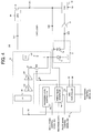
The description will be given of a basic technique of the
present embodiment with reference to FIGS. 1A and 1B. FIG. 1A
shows an example of the recording pulse waveform of the so-called
multi-pulse type. The recording pulse waveform of the multi-pulse
type basically has a top pulse 60, and pulses 61 (hereinafter also
referred to as "multi-pulse") of a number corresponding to the
recording data length. A group of the plural multi-pulses 61 is
called "multi-pulse portion". Dependently on the write strategy,
the short recording data such as 3T and 4T sometimes has only the
top pulse and no multi-pulse portion.
-
As shown in FIG. 1A, the laser power varies between a bias
power level Pb and a write power level Pw. In FIG. 1A, the bias
power level includes a bias power level corresponding to the space
period and a bias power level between the pulses 61 of the multi-pulse
portion. Hereinafter, by defining that the bias power level in
the space period is Pb1 and the bias power level in the multi-pulse
portion is Pb2, the two bias power levels are sometimes
distinguished.
-
In the recording pulse waveform shown in FIG. 1A, when
the bias power level Pb1 in the space period is varied (see an
arrow 70), the front edge position of the top pulse 60 is varied
(see an arrow 75) in accordance with the variation quantity.
Concretely, when the bias power level Pb1 in the space period is
increased, the front edge of the top pulse 60 is shifted backward
(in the right direction of FIG. 1A) by the predetermined quantity.
When the bias power level Pb1 is decreased, the front edge of the
toppulse 60 is shifted forward. By shifting the front edge position
of the top pulse 60, even when the bias power level is varied,
the recording power applied to the disc as a whole becomes equal.
-
In addition, in FIG. 1A, when the bias power level Pb2
of the multi-pulse portion is varied (see an arrow 71), the front
edge position of the multi-pulse 61 in the multi-pulse portion
is varied (see an arrow 7 6) in accordance with the variation quantity.
Concretely, when the bias power level Pb2 is increased, the front
edge of the pulse 61 in the multi-pulse portion is shifted backward
(in the right direction of FIG. 1A) by the predetermined quantity.
When the bias power level Pb2 is decreased, the front edge of the
pulse 61 is shifted forward. By shifting the front edge position
of the pulse 61 in the multi-pulse portion, even when the bias
power level is varied, the recording power applied on the disc
as whole becomes equal.
-
FIG. 1B shows an example of the recording pulse waveform
of the non-multi-pulse type. The recording pulse waveform of the
non-multi-pulse type includes the top pulse 60, a last pulse 67
and an intermediate bias portion 68 between both of them. In a
case of the recording pulse waveform of such the non-multi-pulse
type, the variation method of the pulse shape is basically similar
to the case of the recording pulse waveform of the multi-pulse
type. Namely, when the bias power level Pb1 is varied (see the
arrow 70), in accordance with the variation quantity, the front
edge position of the top pulse 60 is varied (see the arrow 75).
-
As described above, in the present embodiment, by shifting
the front edge position of the top pulse and/or the pulse of the
multi-pulse portion backward and forward in accordance with the
variation of the bias power level, the sum of the laser power
irradiated on the disc by the recording pulse is maintained to
be constant, and deterioration of the recording characteristic
is prevented.
-
FIG. 2 schematically shows a configuration of the
information recording apparatus according to the present
embodiment. In FIG. 2, the information recording apparatus
includes a recording waveform generating unit 50 and a recording
unit 55. The recording waveform generating unit 50 receives the
recording data, and generates the recording pulse signal
correspondent to the inputted recording data in accordance with
predetermined strategy information to supply it to the recording
unit 55. The recording unit 55 has a pickup and the like, for
example. The recording unit 55 drives the laser driver in
accordance with the inputted recording pulse signal, and generates
the recording light to irradiate it on a disc D. In such a way,
the recording mark having a length corresponding to the recording
data is formed on the disc D.
-
The recording waveform generating unit 50 includes a pulse
shape control unit 51 and a first level determining unit 52. A
first level is the bias power level shown in FIGS. 1A and 1B, and
is a concept including both of the bias power level Pb1 in the
space period and the bias power level Pb2 in the multi-pulse portion.
On the contrary, a second level is the write power level Pw.
-
When the recording pulse waveform is generated in
accordance with the specific write strategy shown in FIGS. 1A and
1B, the first level determining unit 52 determines the bias power
level. The concrete determination of the bias power level is
different dependently on various kinds of characteristics of the
information recording apparatus and a drive apparatus to which
the present embodiment is applied. In a certain drive apparatus,
the bias power level Pb may be set to be high, and in another drive
apparatus, the bias power level Pb may be set to be low. In a
certain drive apparatus, the bias power level Pb1 in the space
period can be set to be high, and the bias power level Pb2 in the
multi-pulse portion can be set to be low (or can be conversely
set).
-
In accordance with the first level determined by the first
level determining unit 52, i.e., the bias power level Pb (in some
cases, Pb1 and Pb2), the pulse shape control unit 51 varies the
pulse shape in the recording pulse waveform. Concretely, as
described above, the pulse shape control unit 51 executes a process
as follows. In accordance with increasing/decreasing of the bias
power level Pb1 in the space period, the front edge position of
the top pulse 60 is shifted backward/forward, and in accordance
with increasing/decreasing of the bias power level Pb2 in the
multi-pulse portion, the front edge position of each multi-pulse
61 in the multi-pulse portion is shifted backward/forward. Thus,
the sum of the heat given to the disc is not varied by the variation
of the bias power level, and the stable recording is performed.
-
Next, the description will be given of the specific
embodiment of the present invention.
[Configuration of Information Recording and Reproducing Apparatus]
-
Next, the description will be given of a configuration
of an information recording and reproducing apparatus to which
the above-mentioned recording pulse waveform is applied. FIG.
3 schematically shows an entire configuration of the information
recording and reproducing apparatus according to the specific
embodiment of the invention. An information recording and
reproducing apparatus 1 records information on an optical disc
D and reproduces information from the optical disc D. For example,
the optical disc D may be a CD-R (Compact Disc-Recordable) and
a DVD-R for recording only once, and a CD-RW (Compact
Disc-Rewritable) and a DVD-RW that allow for repeated erasing and
recording of information. It is assumed that the optical disc
D is a DVD-R in an explanation below.
-
The information recording and reproducing apparatus 1
includes an optical pickup 2 for irradiating a recording beam and
a reproduction beam to the optical disc D, a spindle motor 3 for
controlling rotation of the optical disc D, a recording circuit
10 for controlling recording of information on the optical disc
D, a reproduction circuit 20 for controlling reproduction of
information recorded on the optical disc D, a servo control unit
30 for various kinds of servo controls, and a controller 40. The
servo controls include a spindle servo for controlling rotation
of the spindle motor 3, a focus servo and a tracking servo for
controlling a relative position of the optical pickup 2 with respect
to the optical disc D and a tilt servo.
-
The recording circuit 10 receives recording data. Then,
the recording circuit 10 generates a driving signal SD for driving
a laser diode in the optical pickup 2 and supplies it to the optical
pickup 2.
-
The reproduction circuit 20 receives a read-out signal
Srf outputted from the optical pickup 2 and performs predetermined
processing on read-out signal Srf, such as demodulation and decoding,
to generate and output reproduction data.
-
The servo control unit 30 receives the read-out signal
Srf from the optical pickup 2. Based on the signal Srf, the servo
control unit 30 supplies a servo signal S7 such as a tracking error
signal and a focus signal to the optical pickup 2 and supplies
a spindle servo signal S8 to the spindle motor 3. Thus, various
kinds of servo processing are performed, such as the tracking servo,
the focus servo, and the spindle servo.
-
Since the invention mainly relates to the recording
operations in the recording circuit 10 and various known methods
can be applied to the reproduction control and the servo control,
these controls will not be described in detail.
-
The controller 40 forms the recording pulse waveform, and
supplies, to the recording circuit 10, various kinds of control
signals S21 to S23 which will be described later. Further, the
controller 40 supplies, to the servo control unit 30, a signal
S30 showing a recording speed of information, i.e., normal speed
recording, double speed recording or 4-times higher speed
recording.
-
In addition, although FIG. 3 illustrates the information
recording and reproducing apparatus as a specific embodiment of
the invention, the invention may also be applied to an information
recording apparatus dedicated to recording.
-
FIG. 4 shows an internal configuration of the optical pickup
2 and the recording circuit 10. As shown in FIG. 4, the optical
pickup 2 includes a laser diode (LD) 11 which generates the recording
beam for recording information on the optical disc D and the
reproduction beam for reproducing information from the optical
disc D, and a front monitor diode (FMD) 16 which receives the laser
light emitted by the laser diode 11 and outputs a laser power level
signal S10 corresponding to the laser light.
-
The optical pickup 2 further includes known components,
which will not be shown or described in detail. These components
include a photo-detector which receives a reflection beam of the
reproduction beam reflected from the optical disc D and generates
the read-out signal Srf, and an optical system which guides the
recording beam, the reproduction beam and the reflection beam to
appropriate directions.
-
The recording circuit 10 includes a laser diode (LD) driver
12, an APC (Automatic Power Control) circuit 13, a sample-and-hold
(S/H) circuit 14, a controller 15, and a buffer 17.
-
The LD driver 12 supplies a current corresponding to the
recording data to the laser diode (LD) 11, and performs the recording
of the information on the optical disc D.
-
As shown in FIG. 4, the LD driver 12 includes a
voltage-to-current (V/I) converter 121, an interface (I/F) 122,
a D/A converter 124, a driver 126, and a switch SW2.
-
The sample-and-hold circuit 14 samples and holds the level
of the laser power level signal S10 at the timing prescribed by
a sample-and-hold signal S5.
-
The APC circuit 13 performs the power control of the LD
driver 12 based on a signal S11 outputted from the sample-and-hold
circuit 14. Specifically, in the case of DVD-R, the APC circuit
13 controls the LD driver 12 so that the bias power level Pb of
the laser light emitted by the laser diode 11 is maintained constant.
-
The controller 15 mainly performs recording operation and
APC control. As shown in FIG. 4, the controller 15 includes a
write pulse generator 152, a recording level controller 154 and
an APC controller 155.
-
The write pulse generator 152 generates a switching signal
S2 of the switch SW2 in the LD driver 12 on the basis of the inputted
recording data. The pulse-shape control signal S22 is supplied
from the controller 40 to the write pulse generator 152. The
pulse-shape control signal S22 is generated by the controller 40,
and shows the shapes of the top pulse/multi pulse in the recording
pulse signal in accordance with the variation of the bias power
level Pb, more concretely shows the variation quantity of the front
edge position. Therefore, the write pulse generator 152 varies
the front edge positions of the top pulse and/or the multi pulse
in the recording pulse signal based on the pulse-shape control
signal S22.
-
An emission level signal S26 outputted from the
sample-and-hold circuit 14 is supplied to the write pulse generator
152.
-
The recording level controller 154 generates a recording
level signal S3 for determining the write power level on the basis
of the write power control signal S23 inputted from the controller
40 to supply it to the interface (I/F) 122 of the LD driver 12.
The write power control signal S23 shows the level of the write
power Pw (see FIGS. 1A and 1B).
-
The APC controller 155 generates an APC target value S4
which is a target value for servo control performed by an APC loop
to supply it to the APC circuit 13. The APC controller 155 also
supplies, to the sample-and-hold circuit 14, a sample-and-hold
signal S5 which indicates the sampling and holding timings of the
sample-and-hold circuit 14. The target value of the servo control
performed by the APC loop is basically the bias power level Pb
(see FIGS. 1A and 1B), and the controller 40 generates the bias
power control signal S21 indicating the bias power level Pb to
supply it to the APC controller 155. Based on the bias power control
signal S21, the APC controller 155 determines the APC target value
S4. Therefore, the APC loop follows the bias power level Pb
designated by the controller 40.
-
Although the sample-and-hold circuit 14 is used for forming
the APC loop in the above configuration, a bottom hold circuit
may be used instead of the sample-and-hold circuit 14. In that
case, the APC servo may be performed by using a bottom value of
the laser power level signal S10 outputted from the front monitor
diode 16.
[Recording operation]
-
Next, the description will be given of recording control
performed by the recording circuit 10 shown in FIG. 4 using the
optical pickup 2. The recording circuit 10 performs the recording
control and the APC control.
(I) Recording control
-
First, the recording control will be described. It is noted
that the description is first directed to the case of DVD-R. In
the recording operation, the recording level controller 154 in
the controller 15 supplies, to the LD driver 12, the recording
level signal S3 for generating a current I3. The current I3 is
used to create the write power level Pw of the recording pulse
waveform shown in FIG. 1A.
-
The recording level signal S3 is supplied to the D/A
converter 124 through the I/F 122 in the LD driver 12. The D/A
converter 124 generates a correspondent analog signal, and drives
the driver 126 by the analog signal to generate the current I3
and supply it to the switch SW2.
-
The write pulse generator 152 in the controller 15 generates
a write pulse signal which consists of a plurality of pulse trains
based on the recording data shown in FIG. 1A, and supplies it to
the LD driver 12 as the switching signal S2.
-
In the LD driver 12, the current I1 is supplied from the
V/I converter 121 to the laser diode 11. As shown in FIG. 1A,
the current I1 defines the bias power level Pb of the recording
pulse signal.
-
Referring to FIG. 1A, in the mark period, the switch SW2
is controlled by the switching signal S2 identical to the write
pulse signal. Therefore, the switch SW2 is turned on in accordance
with the write pulse signal, and the current I3 is supplied to
the laser diode 11 intermittently. As a result, as shown in FIG.
1A, during the mark period, the recording pulse waveform, whose
level intermittently varies between the bias level (corresponding
to only the current I1) and the write power level (corresponding
to the current I1+I3), is obtained.
-
On the other hand, during the space period, the write pulse
generator 152 generates no write pulse. Therefore, the switch
SW2 is kept turned off and the current I3 is not supplied to the
laser diode 11. Thus, as shown in FIG. 1A, the recording pulse
signal is maintained at the bias power level Pb (corresponding
to the current I1) during the space period.
(II) APC control
-
Next, the APC control will be described. The APC control
is executed at the time of reproduction and during the space period
at the time of recording, but is not performed during the mark
period at the time of recording. The APC control is executed by
the APC loop including the laser diode 11, the front monitor diode
16, the buffer 17, the sample-and-hold circuit 14, the APC circuit
13 and the V/I converter 121.
-
The APC control adjusts the level of the bias current I1
supplied from the LD driver 12 to the laser diode 11 such that
the level of the laser light emitted by the laser diode 11 is always
maintained at the bias power level Pb. Specifically, out of the
space period of the recording data (which is 8-16 modulated and
includes the mark period and the space period of the length of
3T to 11T and 14T), in the long space period (e.g., space period
of 5T to 11T and 14T), the bias current I1 from the LD driver 12
is adjusted such that the bias power level Pb is constant.
-
Details of the operations are as follows. The controller
15 generates the recording pulse waveform corresponding to the
recording data as described above, and drives the LD driver 12
in accordance with the recording pulse waveform to cause the laser
diode 11 to emit the laser light.
-
The front monitor diode 16 is located in proximity to the
laser diode 11 in the optical pickup 2. The front monitor diode
16 receives the laser light emitted by the laser diode 11 to generate
the laser power level signal S10 indicating the level of the laser
light, and supplies the signal S10 to the sample-and-hold circuit
14 through the buffer 17.
-
The sample-and-hold circuit 14 samples the laser power
level signal S10 supplied by the front monitor diode 16 at the
timing given by the sample-and-hold signal S5 supplied by the APC
controller 155 in the controller 15, and holds its level for a
certain period. The sample-and-hold signal S5 outputted from the
controller 15 is a pulse signal indicating the period in which
the signal for the APC control is to be generated. Specifically,
the sample-and-hold signal S5 is a pulse signal indicating a certain
period (a period during which the APC is performed, also referred
to as an "APC period" hereafter) in a relatively long space period
(e.g., 5T to 11T) in the recording data. Thus, the sample-and-hold
circuit 14 samples the level of the laser power level signal S10
in the APC period in the space period of the recording data, and
holds and supplies the sampled level to the APC circuit 13 during
the period other than the APC periods.
-
The APC target value S4 is supplied from the APC controller
155 in the controller 15 to the APC circuit 13. The APC target
value S4 indicates the level of the laser light to be maintained
by the APC. In the present case, the APC target value S4 corresponds
to the bias power level Pb. The APC circuit 13 supplies the control
signal S12 to the V/I converter 121 in the LD driver 12 in order
to maintain the level of the laser power level signal S10 in the
APC periods at a certain level indicated by the APC target value
S4. The V/I converter 121 converts the voltage indicated by the
inputted control signal S12 into a current, and outputs the bias
current I1.
-
At the time of the space period during the recording and
at the time of the reproduction, the laser diode 11 is driven by
the current I1 corresponding to the bias power level Pb, and outputs
the laser light at the bias power level Pb. When the output level
of the laser light outputted by the laser diode 11 is varied due
to the temperature and the like, the APC loop operates so as to
absorb the variation quantity, and varies the bias current I1.
As a result, in the space period, a light output waveform is always
maintained at the bias power level Pb by the APC.
(III) Recording Pulse Waveform Control
-
Next, the description will be given of the control of the
recording pulse waveform. In the present embodiment, the shape
of the recording pulse waveform is controlled by the control signals
S21 to S23 supplied to the recording circuit 10 by the controller
40. As described above, in accordance with the variation of the
bias power level Pb, the controller 40 varies the shape of the
recording pulse waveform.
-
Concretely, first, the controller 40 supplies the write
power control signal S23 indicating the write power level Pw (see
FIGS. 1A and 1B) to the recording level controller 154. The
recording level controller 154 sets the write power level Pw to
the level indicated by the write power control signal S23.
-
The controller 40 supplies the bias power control signal
S21 indicating the bias power level Pb to the APC controller 155.
The controller 40 can vary the bias power level Pb on the basis
of various kinds of reasons. The various kinds of reasons are
to set the bias power level to a predetermined value higher than
a prescribed value for stabilization of the servo control, and
to set the bias power level to the predetermined value lower than
the prescribed value for improvement of the recording
characteristic, for example. Then, the controller 40 supplies,
to the APC controller 155, the bias power control signal S21
indicating the bias power level thus varied. The APC controller
155 outputs the target value S4 in order to maintain the bias power
level Pb to the level indicated by the bias power control signal
S21 to execute the APC.
-
At the same time, the controller 40 supplies, to the write
pulse generator 152, the pulse-shape control signal S22 which
adjusts the pulse-shape in the recording pulse waveform
corresponding to the variation of the bias power level indicated
by the bias power control signal S21. For example, when the
controller 40 outputs, to the APC controller 155, the bias power
control signal S21 indicating that the bias power level is increased
to be larger than the prescribed value by the predetermined value,
the controller 40 supplies, to the write pulse generator 152, the
pulse-shape control signal S22 designating that the front edge
of the top pulse in the recording pulse waveform is shifted backward
by the predetermined quantity accordingly. Thereby, the write
pulse generator 152 generates such the recording pulse waveform
that the front edge of the top pulse in the recording pulse waveform
is shifted backward by the predetermined quantity, and controls
the switch SW2 to drive the laser diode 11.
-
At the time of varying the bias power level Pb, the controller
40 controls the write pulse generator 152 so that the front edge
of the pulse (top pulse and/or multi-pulse) in the recording pulse
waveform is shifted in accordance with the variation quantity.
-
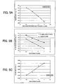
As an example, FIG. 5A shows a relation between the bias
power Pm of the multi-pulse portion and the multi-pulse width Tmp
according to it. In accordance with the increase of the bias power
level of the multi-pulse portion, the multi-pulse width Tmp is
decreased. Thereby, it can be prevented that the recording
characteristic is deteriorated due to the variation of the bias
power level.
(IV) Correction of Recording Pulse Waveform
-
Next, the description will be given of correction of the
recording pulse waveform. In the above-mentioned method, the
controller 40 varies the bias power level, the front edge position
of the recording pulse waveform is varied in order to correspond
to the variation. However, actually, it is not always ensured
that the recording light is emitted according to the deformation
of the recording pulse waveform by the pulse-shape control signal
S22 and the expected recording power is irradiated on the disc.
For example, the recording power actually irradiated on the disc
is sometimes different from the value expected by the controller
40 due to a variation of the laser diode characteristic, a warp
of the recording surface of the disc and the like. Therefore,
it is preferable that the actual variation of the bias power is
monitored directly or indirectly and adjustment of the recording
pulse waveform is performed in accordance with the variation
quantity. The adjustment can be performed by three methods below.
As for the known variation of the bias power incapable of being
monitored, the adjustment is performed in advance by a method
different from the three methods below.
-
In a first method, the laser emission power corresponding
to the bias power set by the APC controller 155 is detected by
using the front monitor diode 16 of the pickup 2, and the laser
emission power is fed back to the write pulse generator 152. Thereby,
the correction of the recording pulse waveform is performed.
Concretely, as shown in FIG. 4, the detecting signal S26 of the
sample-and-hold circuit 14 is inputted to the write pulse generator
152, and the write pulse generator 152 performs the correction
of the recording pulse waveform in accordance with the detecting
signal S26.
-
In a second method, a return light of the recording laser
light irradiated on the disc is used. Concretely, the output signal
of the photo detector provided in the pickup 2 may be supplied
from the reproduction circuit 20 shown in FIG. 3 to the write pulse
generator 152. Since the variation of a thermal effective value
of the bias power due to the sensitivity difference of the disc
can be detected by the variation of the return light during the
recording. Therefore, by correcting the recording pulse waveform
based on it, the sensitive difference of the disc can be absorbed.
-
In a third method, a tilt servo control signal generated
by the servo control unit 30 shown in FIG. 3 is supplied to the
write pulse generator 152. Since a variation of the thermal
effective value of the bias power due to the tilt shift can be
detected from the tilt servo control signal, by similarly detecting
the bias power actually irradiated on the disc, the recording pulse
waveform can be corrected.
-
When the bias power actually irradiated on the disc is
detected by any one of the above methods, the correction of the
recording pulse waveform is performed based on it. It is assumed
that the controller 40 inputs, to the APC controller 155, the bias
power control signal S21 increasing the bias power level by the
predetermined value, and supplies, to the write pulse generator
152, the pulse-shape control signal S22 designating that the front
edge of the top pulse of the recording pulse waveform is shifted
by the predetermined quantity, for example. However, when it is
found that the bias power level irradiated on the disc is actually
increased by only a half due to the characteristic of the laser
diode 11 and the warp of the disc, the write pulse generator 152
performs the correction of returning the front edge position of
the top pulse of the recording pulse waveform to the original
position by only the half. Thereby, the recording can accurately
be performed in consideration of the laser power actually irradiated
on the disc.
-
Instead of performing the correction of the recording pulse
waveform as described above, the bias power can be varied. In
addition, both corrections of the recording pulse waveform and
the bias power can be performed.
(V) Correction of Recording Pulse Waveform after Short Space
-
As described above, basically in accordance with the
increase of the bias power level, the adjustment of the recording
pulse waveform may be performed. However, when a short mark such
as the 3T mark is recorded after a short space such as the 3T space,
it is easily affected by a thermal interference. Therefore, it
is effective to increase the adjustment quantity of the recording
pulse waveform, i.e., the shift quantity of the front edge of the
top pulse, after the short space such as the 3T space.
-
FIG. 5B shows an example of the shift quantity in such
a case. Each value such as a pulse width shown in FIGS. 5A to
5C corresponds to each portion shown in FIG. 6. FIG. 5B shows
a relation between the bias power Pb and the top pulse width Ttop
for the 3T mark after the 3T space and other 3T marks. As shown
in FIG. 5B, in the case of the 3Tmarkafter the 3T space, in comparison
with other 3T marks, the top pulse width is set to be small with
respect to the identical bias power, i.e., the shift quantity of
the front edge position backward is set to be large.
-
FIG. 5C shows differences of appropriate front edge shift
quantities Tld of the top pulses for the 3T mark subsequent to
the 3T space and other 3T marks, when an identical bias power is
set. It is understood that as the 3T bias power becomes higher,
it becomes necessary to make a front edge shift quantity Tld of
the top pulse much larger. Thereby, the effect of the thermal
interference in the case that the bias power is increased in the
short space portion such as the 3T space can be decreased.
(VI) Correction Example of Recording Pulse Waveform
-
Next, the description will be given of another correction
example of the recording pulse waveform. In the above explanation,
the description was given of such the method that the front edge
of the top pulse and/or the multi-pulse of the recording pulse
waveform is shifted backward in accordance with the increase of
the bias power level. However, if the sum of a heat quantity by
the entire recording pulse waveform can be decreased and/or
increased in accordance with the quantity of increase and/or
decrease of the bias power level, the recording pulse waveform
can be corrected by the methods other than the method of shifting
the front edge of the top pulse. Some examples including such
case are shown below.
-
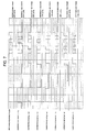
FIG. 7 shows correction examples in a case that the write
strategy of the multi-pulse type is used.
-
The correction examples 1-1 and 1-2 are the above-described
methods. In the correction example 1-1, since the bias power level
is lower than a reference bias power level, the front edges of
the top pulse and the multi-pulse are shifted forward
correspondingly. Conversely, in the correction example 1-2, since
the bias power level is higher than the reference bias power level,
the front edges of the top pulse and the multi-pulse are shifted
backward.
-
In a correction example 1-3, since only the bias power
level in the space period is lower than the reference bias power
level, a back edge of the top pulse in the pulse waveform before
the space period is shifted backward, and the front edge of the
top pulse in the pulse waveform following the space period is shifted
forward. Since the bias power level in the multi-pulse portion
is equal to the reference bias power level, the multi-pulse does
not vary.
-
In a correction example 1-4, since the bias power level
in the space period after the recording pulse is high for a certain
period, the back edge of the recording pulse is shifted forward,
and the front edge of the next recording pulse is shifted backward.
-
In a correction example 1-5, since the bias power level
in the space period after the recording pulse is high for a certain
period, the front edge of the next recording pulse is shifted
backward.
-
In a correction example 1-6, since the bias power level
in the space period before the recording pulse is low for a certain
period, the front edge of the top pulse of the recording pulse
is shifted forward.
-
In a correction example 1-7, since the bias power level
of the multi-pulse portion is high, the front edge of each
multi-pulse is shifted backward respectively.
-
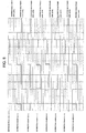
On the other hand, FIG. 8 shows such correction examples
that a write strategy of a non-multi-type is used.
-
In a correction example 2-1, since the bias power level
is lower than the reference bias power level, the front edge of
the top pulse is shifted forward correspondingly. Though FIG.
8 does not show, conversely to the correction example 2-1, when
the bias power level in the space period is high, the front edge
of the top pulse of the subsequent recording pulse waveform may
be shifted backward.
-
In a correction example 2-2, since the bias power level
in the space period is higher than the reference bias power level,
the back edge of the last pulse in the recording pulse before the
space period is shifted forward.
-
In a correction example 2-3, since the bias power level
in the space period is lower than the reference bias power level,
the back edge of the last pulse in the recording pulse before the
space period is shifted backward, and the front edge of the top
pulse in the recording pulse after the space period is shifted
forward.
-
In a correction example 2-4, since the bias power level
in the space period after the recording pulse is high for a certain
period, the back edge of the recording pulse is shifted forward,
and the front edge of the next recording pulse is shifted backward.
-
In a correction example 2-5, since the bias power level
in the space period after the recording pulse is high for a certain
period, the front edge of the next recording pulse is shifted
backward.
-
In a correction example 2-6, since the bias power level
in the space period before the recording pulse is low for a certain
period, the front edge of the top pulse of the recording pulse
is shifted forward.
-
In a correction example 2-7, since the bias power level
in the space period before the recording pulse is low, the back
edge of the top pulse of the recording pulse is shifted backward
correspondingly (i.e., the intermediate bias period is shortened).
-
As explained above, in the embodiment of the present
invention, the shape of the recording pulse waveform is varied
in accordance with the variation of the bias power. Therefore,
the total heat quantity of the recording laser light irradiated
on the disc as a whole can be maintained, and a preferable recording
characteristic can be maintained.
INDUSTRIAL APPLICABILITY
-
The information recording apparatus and the information
recording method according to the present invention can be utilized
when the information is recorded on the optical disc by using the
laser light.