EP1547633B1 - A piston for a syringe and a prefilled syringe using the same - Google Patents
A piston for a syringe and a prefilled syringe using the same Download PDFInfo
- Publication number
- EP1547633B1 EP1547633B1 EP04256210A EP04256210A EP1547633B1 EP 1547633 B1 EP1547633 B1 EP 1547633B1 EP 04256210 A EP04256210 A EP 04256210A EP 04256210 A EP04256210 A EP 04256210A EP 1547633 B1 EP1547633 B1 EP 1547633B1
- Authority
- EP
- European Patent Office
- Prior art keywords
- piston
- syringe
- injection barrel
- skirt part
- injection
- Prior art date
- Legal status (The legal status is an assumption and is not a legal conclusion. Google has not performed a legal analysis and makes no representation as to the accuracy of the status listed.)
- Not-in-force
Links
Images
Classifications
-
- A—HUMAN NECESSITIES
- A61—MEDICAL OR VETERINARY SCIENCE; HYGIENE
- A61M—DEVICES FOR INTRODUCING MEDIA INTO, OR ONTO, THE BODY; DEVICES FOR TRANSDUCING BODY MEDIA OR FOR TAKING MEDIA FROM THE BODY; DEVICES FOR PRODUCING OR ENDING SLEEP OR STUPOR
- A61M5/00—Devices for bringing media into the body in a subcutaneous, intra-vascular or intramuscular way; Accessories therefor, e.g. filling or cleaning devices, arm-rests
- A61M5/50—Devices for bringing media into the body in a subcutaneous, intra-vascular or intramuscular way; Accessories therefor, e.g. filling or cleaning devices, arm-rests having means for preventing re-use, or for indicating if defective, used, tampered with or unsterile
- A61M5/5013—Means for blocking the piston or the fluid passageway to prevent illegal refilling of a syringe
-
- A—HUMAN NECESSITIES
- A61—MEDICAL OR VETERINARY SCIENCE; HYGIENE
- A61M—DEVICES FOR INTRODUCING MEDIA INTO, OR ONTO, THE BODY; DEVICES FOR TRANSDUCING BODY MEDIA OR FOR TAKING MEDIA FROM THE BODY; DEVICES FOR PRODUCING OR ENDING SLEEP OR STUPOR
- A61M5/00—Devices for bringing media into the body in a subcutaneous, intra-vascular or intramuscular way; Accessories therefor, e.g. filling or cleaning devices, arm-rests
- A61M5/178—Syringes
- A61M5/31—Details
- A61M5/315—Pistons; Piston-rods; Guiding, blocking or restricting the movement of the rod or piston; Appliances on the rod for facilitating dosing ; Dosing mechanisms
- A61M5/31511—Piston or piston-rod constructions, e.g. connection of piston with piston-rod
-
- A—HUMAN NECESSITIES
- A61—MEDICAL OR VETERINARY SCIENCE; HYGIENE
- A61M—DEVICES FOR INTRODUCING MEDIA INTO, OR ONTO, THE BODY; DEVICES FOR TRANSDUCING BODY MEDIA OR FOR TAKING MEDIA FROM THE BODY; DEVICES FOR PRODUCING OR ENDING SLEEP OR STUPOR
- A61M2205/00—General characteristics of the apparatus
- A61M2205/02—General characteristics of the apparatus characterised by a particular materials
- A61M2205/0222—Materials for reducing friction
-
- A—HUMAN NECESSITIES
- A61—MEDICAL OR VETERINARY SCIENCE; HYGIENE
- A61M—DEVICES FOR INTRODUCING MEDIA INTO, OR ONTO, THE BODY; DEVICES FOR TRANSDUCING BODY MEDIA OR FOR TAKING MEDIA FROM THE BODY; DEVICES FOR PRODUCING OR ENDING SLEEP OR STUPOR
- A61M2205/00—General characteristics of the apparatus
- A61M2205/02—General characteristics of the apparatus characterised by a particular materials
- A61M2205/0238—General characteristics of the apparatus characterised by a particular materials the material being a coating or protective layer
-
- A—HUMAN NECESSITIES
- A61—MEDICAL OR VETERINARY SCIENCE; HYGIENE
- A61M—DEVICES FOR INTRODUCING MEDIA INTO, OR ONTO, THE BODY; DEVICES FOR TRANSDUCING BODY MEDIA OR FOR TAKING MEDIA FROM THE BODY; DEVICES FOR PRODUCING OR ENDING SLEEP OR STUPOR
- A61M5/00—Devices for bringing media into the body in a subcutaneous, intra-vascular or intramuscular way; Accessories therefor, e.g. filling or cleaning devices, arm-rests
- A61M5/178—Syringes
- A61M5/31—Details
- A61M5/315—Pistons; Piston-rods; Guiding, blocking or restricting the movement of the rod or piston; Appliances on the rod for facilitating dosing ; Dosing mechanisms
- A61M5/31511—Piston or piston-rod constructions, e.g. connection of piston with piston-rod
- A61M5/31513—Piston constructions to improve sealing or sliding
-
- A—HUMAN NECESSITIES
- A61—MEDICAL OR VETERINARY SCIENCE; HYGIENE
- A61M—DEVICES FOR INTRODUCING MEDIA INTO, OR ONTO, THE BODY; DEVICES FOR TRANSDUCING BODY MEDIA OR FOR TAKING MEDIA FROM THE BODY; DEVICES FOR PRODUCING OR ENDING SLEEP OR STUPOR
- A61M5/00—Devices for bringing media into the body in a subcutaneous, intra-vascular or intramuscular way; Accessories therefor, e.g. filling or cleaning devices, arm-rests
- A61M5/50—Devices for bringing media into the body in a subcutaneous, intra-vascular or intramuscular way; Accessories therefor, e.g. filling or cleaning devices, arm-rests having means for preventing re-use, or for indicating if defective, used, tampered with or unsterile
- A61M5/5013—Means for blocking the piston or the fluid passageway to prevent illegal refilling of a syringe
- A61M5/502—Means for blocking the piston or the fluid passageway to prevent illegal refilling of a syringe for blocking the piston
Definitions
- This invention relates to a sealing stopper or piston for a syringe provided with a backstop function and to a prefilled syringe using the same.
- the prefilled syringe is of a disposal type such that the prefilled syringe, once used, should be abandoned from a sanitary problem such as infectious disease.
- a syringe provided with such a mechanism for example, there is a structure in which a plunger threaded with a piston has a reuse-prevention projection which is to be engaged with a recess of an injection barrel when the plunger is pushed, so that the plunger cannot be withdrawn (called backstop), as shown in WO 01/64266 A1 .
- backstop a reuse-prevention projection which is to be engaged with a recess of an injection barrel when the plunger is pushed, so that the plunger cannot be withdrawn (called backstop), as shown in WO 01/64266 A1 .
- the mechanism of this syringe is so complicated that its production cost is considerably increased.
- US-A-4,781,684 relates to a single use disposable hypodermic syringe with a first and second portion to prevent removal of the piston from the syringe barrel.
- GB-A-2,340,042 discloses a one-use hypodermic syringe wherein the barrel of the syringe comprises a constricted region that retains a therein inserted piston head so that it disconnects from the plunger if the plunger is withdrawn.
- a piston for a syringe for sealing an injection barrel filled with a medicament comprising a skirt part capable of serving as a backstop device.
- the inventors have made various efforts to impart a reuse-preventive mechanism to a prefilled syringe and consequently, have found that the reuse-preventive device can economically be given to the syringe by composing a stopper for a prefilled syringe to have a backstop function.
- the present invention is based on this finding. That is, the present invention has the following constructive features:
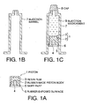
- Fig. 1 is a schematic cross-sectional view of one embodiment of a piston for a syringe (which will hereinafter be referred to as "piston") and a prefilled syringe using the same according to the present invention
- the piston 1 shown as (a) in Fig. 1 comprises a rubber-made piston body 2, the surface of which is laminated with a resin film 3.
- a plunger rod 4 (not shown) is fitted to the piston at a fitted position.
- the end of an injection barrel 7 is sealed by a cap 8 as shown in Fig. 1, (c) , after which an injection medicament 9 is filled and prepared in an injection barrel 7 shown in Fig. 1 (b) and sealed by the piston 1 to give the prefilled syringe.
- a needle part, plunger part and cover parts for each part are added thereto to prepare a finished article.
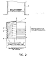
- Fig. 2 there is shown another embodiment of a piston for a syringe according to the present invention, as enlarged in part and as a front view in part, in which the same remarks as those in Fig. 1 have the same meaning.
- the piston 1 has a skirt part 5 having a backstop function.
- the piston 1 is subjected to film 3 lamination and/or lubricant coating on the surface thereof and it is desirable to allow a contact surface of the skirt part 5 with the inner wall of the injection barrel 7 to provide with the rubber exposed surface 6, since a friction resistance is increased when a drawing force is applied to the piston 1.
- the above described rubber exposed surface 6 is inside the maximum outer diameter of the piston and outside the inner diameter of the injection barrel.
- the maximum outer diameter b of the piston 1 is ordinarily enlarged to be larger than the inner diameter c of the injection barrel 7, and the position of the rubber exposed surface 6 is so controlled as to impart such a degree that the rubber exposed surface 6 is not so strongly contacted with the injection barrel 7 that the resistance during compressing is not so excessive and a backstop action can be given when a drawing force is applied.
- the maximum diameter a of the rubber exposed surface 6 is smaller than the maximum outer diameter b of the piston 1 and is larger than the inner diameter c of the injection barrel 7 (c ⁇ a ⁇ b) .
- the object of the present invention can be achieved if at least a part of the rubber exposed surface 6 is contacted with the inner surface of the injection barrel 7 and a diameter a' when the skirt part 5 is wound is larger than the inner diameter c (a'>c), even if a ⁇ c regarding the above described a and c.
- Such a structure is most preferable that when the piston 1 is compressed (advanced) in the injection barrel 7, only a part of the rubber exposed surface 6 is contacted with the inner surface of the injection barrel 7, and when it is drawn (backed), the whole circumference-of the skirt part 5 is contacted with the inner surface of the injection barrel 7 to cause a backstop action. This is due to that when the piston 1 is advanced, the slidable resistance is suppressed to a minimum limit and when it is backed, a sufficient resistance enough to backstop the piston 1 can be obtained.
- the skirt part 5 has an angle ( ⁇ in Fig. 2 ) of the skirt part in a range of preferably 30 to 80° , more preferably 40 to 70° based on a standard surface vertical to such a direction that the piston for a syringe is slidably moved in the injection barrel.
- angle ⁇ is at least 30°
- the width of the skirt part 5 can sufficiently be maintained, a friction resistance sufficient enough to backstop the piston 1 can be obtained and the slidable resistance is not enlarged to be more than the required value when the piston 1 is advanced in the injection barrel 7.
- the skirt part 5 can well be turned up when the piston 1 is backed away.
- the skirt part 5 of the piston 1 shown in Fig. 2 is over the whole circumference of the stopper, but it is not always provided over the whole circumference, but can intermittently be provided.
- the position of the skirt part 5 is part at the end of the plunger side as shown in Fig. 2 from the standpoint of ease of the production.
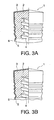
- Fig. 3(a) and (b) are cross-sectional views of other embodiments of the piston 1 according to the present invention, where the piston 1 has the skirt part 5 in the form of other shapes
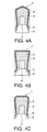
- Fig. 4(a) to (c) are cross-sectional views of further embodiments of the piston 1 according to the present invention in the form of further shapes, in which the same remarks as those in Fig. 1 and Fig. 2 have the same meanings.
- a case of laminating a rubber-made piston body 2 with a resin film 3 is exemplified, and the laminated resin film 3 is not limited thereto but any material capable of obtaining a required kinematic friction coefficient (e.g. a kinematic friction coefficient of at most 0.2 measured according to JIS K 7218-1986) when fitted to a plunger and pushed into an injection barrel 7 can be used. Accordingly, other known means such as coating of lubricants can be selected for this purpose.
- a required kinematic friction coefficient e.g. a kinematic friction coefficient of at most 0.2 measured according to JIS K 7218-1986
- fluoro resins such as tetrafluoro ethylene resin (PTFE), tetrafluoroethylene-perfluoroethylene copolymer (PFA), tetrafluoroethylene-hexafluoropropylene copolymer (FEP), tetrafluoroethylene-ethylene copolymer (ETFE), trichlorotrifluoroethylene (PCTFE), poly-vinylidene fluoride (PVDF), polyvinyl fluoride (PVF), etc. and further, can also be used ultra-high molecular weight polyethylene, etc. in addition to the fluoro resins.
- PTFE tetrafluoro ethylene resin
- PFA tetrafluoroethylene-perfluoroethylene copolymer
- FEP tetrafluoroethylene-hexafluoropropylene copolymer
- ETFE tetrafluoroethylene-ethylene copolymer
- PCTFE trichlorotrifluoro
- Lamination of a rubber-made piston body 2 with a resin film 3 can be carried out by a known prior art technique, for example, a method comprising optionally subjecting one surface of a film to a chemical treatment (chemical etching), sputter etching or corona discharge, arranging it in a shaping mold with a rubber compound to be a basic material for the piston body 1, and then vulcanizing or bonding to form into a pre-determined shape.
- a chemical treatment chemical etching
- sputter etching or corona discharge arranging it in a shaping mold with a rubber compound to be a basic material for the piston body 1, and then vulcanizing or bonding to form into a pre-determined shape.
- a site to be laminated includes a part that can be contacted with the inner wall of the injection barrel 7 or with a medicament, etc., without intending to be limited thereto, in addition to at least a part (rubber exposed surface 6) of the contacted surface of the skirt part 5 with the inner wall of the injection barrel 7.
- a site to be coated with the lubricant includes a part that can be contacted with the inner wall of the injection barrel 7, etc. without intending to be limited thereto, in addition to at least a part (rubber exposed surface 6) of the contacted surface of the skirt part 5 with the inner wall of the injection barrel 7.
- a method comprising molding a rubber in the form of a sheet consisting of a number of rubber-made piston bodies 2 bonded at the skirt part 5, subjecting the resulting sheet to laminate working or lubricant coating in the form of the sheet and then separating the contacted surface of the skirt part 5 with the injection barrel 7.
- a rubber for the material of the rubber-made piston body 2 of the piston is not particularly limited, but can for example be selected from synthetic rubbers or natural rubbers such as butyl rubbers, chlorinated butyl rubbers, isobutylene-isoprene-divinylbenzene-ternary polymerization partially cross-linked butyl rubbers, acrylnitrile-butadiene-rubbers, isoprene rubbers, butadiene rubbers, styrene-butadiene rubbers, ethylene-propyrene rubbers, isoprene-isobutylene rubbers, nitrile rubbers, etc., as a predominant component, to be compounded with fillers, cross-linking agents or the like.
- synthetic rubbers or natural rubbers such as butyl rubbers, chlorinated butyl rubbers, isobutylene-isoprene-divinylbenzene-ternary polymerization partially cross-linked butyl rubbers, acrylnit
- thermoplastic elastomer there can also be used solution polymerization type styrene-butadiene rubbers (SBS block copolymer), polyester or polyether urethane rubbers, polyether aromatic polyester block copolymers (polyester rubbers), polyolefin block copolymers, high trans-1,4-polyisoprenes, polyethylenebutyl graft copolymers, syndiotactic polybutadiens and the like.
- SBS block copolymer solution polymerization type styrene-butadiene rubbers
- polyester or polyether urethane rubbers polyester or polyether urethane rubbers
- polyether aromatic polyester block copolymers polyether aromatic polyester block copolymers
- polyolefin block copolymers high trans-1,4-polyisoprenes
- polyethylenebutyl graft copolymers syndiotactic polybutadiens and the like.
- relatively soft plastics for example, plastics of copolymer type and having substantially the same heat resistance (preferably about 130 to 140 °C) as poly-propylene, such as polypropylenes of copolymer type, low density polyethylenes, ethylene-vinyl acetate copolymers, etc. can also be used.
- the hardness of the piston of the present invention is not particularly limited, but is suitably selected depending on the shape or the like of the piston and from the standpoint of maintaining the sealing property of a prefilled syringe and compressing the piston with a suitable force as well as effectively exhibiting the backstop function, the hardness is preferably measured by a method defined by JIS K 6253 A, which is preferably within a range of 50 to 65, more preferably 55 to 60.
- the piston of the present invention in particular, it is eagerly desired to select a material excellent in antigaspermeability so as to obtain high sanitary property as well as stably preserve a solvent for a long time, e.g. three years in a container (injection barrel).
- Table 1 Composition Compounding Example 1 2 3 4 Butyl Rubber 1) 100 Chlorinated Butyl Rubber 2) 100 Isobutylene-Isoprene-Divinylbenzene-Ternary Polymerization Partially Cross-linked Butyl Rubber 3) 100 Acrylnitrile-Butadiene Rubber 4) 100 Wet process Hydrous Silica 5) 35 30 30 20 Dipentanemethylene Thiuram Tetrasulfide 6) 2.5 Zinc Di-n-dibutylthiocarbamate 7) 1.5 Active Zinc Oxide 8) 5 4 1.5 Stearic Acid 9) 1.5 3 Magnesium Oxide 10) 1.5 2-Di-n-Butylamino-4,6-dimercapto-s-triazine 11) 1.5 1-1-Bis(t-butylperoxy)-3,3,5-trimethylcyclohexane 12) 2 8 Total (by weight) 145.5 140.0 133.5 128 Vulcan
- the prefilled syringe of the present invention includes any type of prefilled syringes using the piston for a syringe illustrated above according to the present invention and the material or shape of the injection barrel part and other parts than the injection barrel, for example, the cap at the front end, injection needle part, plunger rod fitted to the rear end of the piston or the like is not particularly limited.
- the material of the injection barrel (-cum-container)
- plastics are generally used from the viewpoint of the surface roughness, such as cyclic olefinic resins, cyclic olefin-ethylene copolymers, polyethylene terephthalate type resins, polystyrene resins, etc.
- it is preferable to selectively use cyclic olefinic resins or cyclic olefin-ethylene copolymers e.g. used for a sanitary container described in JP-B2-2914826 ).
- the prefilled syringe of the present invention includes any type of syringes using the sealing stopper as a piston according to the present invention, that is, not only one as shown in Fig. 1(c) , but also two compartment type syringes, e.g. as shown in JP-A-8-308688 .
- the sealing stopper or piston for a syringe according to the present invention has a skirt part provided with a backstop function, compressing of the piston can be carried out in an injection barrel, but drawing thereof cannot be carried out.
- reuse preventive function can be given in economical and simple manner. That is, the prefilled syringe using the above described sealing stopper of piston for a syringe can be provided with the reuse-preventive function with a low cost and can be prevented from such a danger that a syringe having been thrown away is used again.
Abstract
Description
- This invention relates to a sealing stopper or piston for a syringe provided with a backstop function and to a prefilled syringe using the same.
- As a method of feeding an injection agent as one agent form of a medicament to a medical scene, there is such a system of the so-called prefilled syringe that the injection agent is previously prepared (charged) in a syringe-cum-container, transported and storaged while the end parts thereof are sealed by the piston, the front end of an injection barrel is fitted with an injection needle or administration device during administration, and the piston is forcedly thrusted in the front end and slidably moved in the injection barrel to cause the injection agent to flow out of the injection needle side, as referred to
JP-B2-3387775 - Since the above described syringe, once used, is ordinarily abandoned, under usable state if refilled with a liquid medicament, however, there is such a possibility that the abandoned syringe can be reused for a criminal act such as injection of stimulants and is misused again in a medical scene. In order to completely prevent from these dangers, it is desired to provide such a mechanism that the once used syringe is no longer used again.
- As a syringe provided with such a mechanism, for example, there is a structure in which a plunger threaded with a piston has a reuse-prevention projection which is to be engaged with a recess of an injection barrel when the plunger is pushed, so that the plunger cannot be withdrawn (called backstop), as shown in
WO 01/64266 A1 -
US-A-4,781,684 relates to a single use disposable hypodermic syringe with a first and second portion to prevent removal of the piston from the syringe barrel. - It discloses a piston according to the preamble of
claim 1. -
GB-A-2,340,042 - It is an object of the present invention to provide a prefilled syringe provided with a backstop function without increasing the production cost therof, whereby the disadvantages of the prior art can be overcome.
- It is another object of the present invention to provide a sealing stopper or a piston for a syringe, having a reuse preventive backstop mechanism, in economical manner.
- These objects can be achieved by a piston for a syringe for sealing an injection barrel filled with a medicament, comprising a skirt part capable of serving as a backstop device.
- The accompanying drawings are to illustrate the principle and merits of the present invention in detail.
-
Fig. 1 is a cross-sectional view of one embodiment of a piston for a syringe and a prefilled syringe using the same according to the present invention, (a) a piston or sealing stopper, (b) a injection barrel and (c) a prefilled syringe. -
Fig. 2 is a cross-sectional view of another embodiment of a piston for a syringe, in part, according to the present invention, illustrating dimensions of each part. -
Fig. 3 is a cross-sectional view of a further embodiment of a piston for a syringe, in part according to the present invention, respectively differing in shape of skirt of part of pistons (a) and (b). -
Fig. 4 is a cross-sectional view of a still further embodiment of a piston for a syringe according to the present invention, respectively differing in shape in cross-section (a), (b) and (c). - We, the inventors have made various efforts to impart a reuse-preventive mechanism to a prefilled syringe and consequently, have found that the reuse-preventive device can economically be given to the syringe by composing a stopper for a prefilled syringe to have a backstop function. The present invention is based on this finding. That is, the present invention has the following constructive features:
- 1. A piston (1) for sealing an injection barrel (7) of a syringe, which, in use, is filled with a medicament, the piston (1) comprising:
- a piston body (2); and
- a skirt part (5);
- the piston (1) is film (3) laminated and/or lubricant coated,
- the skirt part (5) is shaped and arranged so as to allow, in use, movement of the piston (1) in a direction along a longitudinal axis of the injection barrel (7), and to engage, in use, the injection barrel (7) to prevent movement of the piston (1) in an opposite direction along the longitudinal axis of the injection barrel (7),
- characterised in that the skirt part (5) is arranged at a plunger end of the piston body (2) and has a rubber exposed surface (6) to contact, in use, an injection barrel
- wherein the angle of the skirt part (5) is in a range of 30 to 80° based on a standard surface vertical to a direction in which the piston (1) is slidably moved in the injection barrel (7).
- 2. A syringe comprising a piston (1) as described in the above 1, and an injection barrel (7).
- 3. A syringe as described in the above 2, wherein:
- at least a part of the skirt part (5) is inside of a maximum outer diameter (b) of the piston (1);
- and the skirt part (5) has an uncompressed outer diameter (a) which is greater than an inner diameter (c) of the injection barrel (7).
- 4. A prefilled syringe comprising an injection barrel (7) filled with a medicament (9) and sealed by a piston (1) as described in the above1.
- 5. A prefilled syringe comprising a syringe as defined in the above 2 or 3, wherein the injection barrel (7) is filled with a medicament (9) and sealed by the piston (1).
-
Fig. 1 is a schematic cross-sectional view of one embodiment of a piston for a syringe (which will hereinafter be referred to as "piston") and a prefilled syringe using the same according to the present invention, thepiston 1 shown as (a) inFig. 1 comprises a rubber-madepiston body 2, the surface of which is laminated with aresin film 3. A plunger rod 4 (not shown) is fitted to the piston at a fitted position. In a preparation step for an injection medicament, the end of aninjection barrel 7 is sealed by acap 8 as shown inFig. 1, (c) , after which aninjection medicament 9 is filled and prepared in aninjection barrel 7 shown inFig. 1 (b) and sealed by thepiston 1 to give the prefilled syringe. Ordinarily, a needle part, plunger part and cover parts for each part (all not shown) are added thereto to prepare a finished article. - In
Fig. 2 , there is shown another embodiment of a piston for a syringe according to the present invention, as enlarged in part and as a front view in part, in which the same remarks as those inFig. 1 have the same meaning. - The
piston 1 has askirt part 5 having a backstop function. Thepiston 1 is subjected tofilm 3 lamination and/or lubricant coating on the surface thereof and it is desirable to allow a contact surface of theskirt part 5 with the inner wall of theinjection barrel 7 to provide with the rubber exposedsurface 6, since a friction resistance is increased when a drawing force is applied to thepiston 1. - Moreover, it is desirable that at least a part of the above described rubber exposed
surface 6 is inside the maximum outer diameter of the piston and outside the inner diameter of the injection barrel. In order to ensure the sealing property, the maximum outer diameter b of thepiston 1 is ordinarily enlarged to be larger than the inner diameter c of theinjection barrel 7, and the position of the rubber exposedsurface 6 is so controlled as to impart such a degree that the rubber exposedsurface 6 is not so strongly contacted with theinjection barrel 7 that the resistance during compressing is not so excessive and a backstop action can be given when a drawing force is applied. - When the central axis of the
piston 1 and that of theskirt part 5 become complete, for example, it is preferable that the maximum diameter a of the rubber exposedsurface 6 is smaller than the maximum outer diameter b of thepiston 1 and is larger than the inner diameter c of the injection barrel 7 (c<a<b) . When the central axis of thepiston 1 and that of theskirt part 5 are shifted, the object of the present invention can be achieved if at least a part of the rubber exposedsurface 6 is contacted with the inner surface of theinjection barrel 7 and a diameter a' when theskirt part 5 is wound is larger than the inner diameter c (a'>c), even if a<c regarding the above described a and c. Such a structure is most preferable that when thepiston 1 is compressed (advanced) in theinjection barrel 7, only a part of the rubber exposedsurface 6 is contacted with the inner surface of theinjection barrel 7, and when it is drawn (backed), the whole circumference-of theskirt part 5 is contacted with the inner surface of theinjection barrel 7 to cause a backstop action. This is due to that when thepiston 1 is advanced, the slidable resistance is suppressed to a minimum limit and when it is backed, a sufficient resistance enough to backstop thepiston 1 can be obtained. - Furthermore, the
skirt part 5 has an angle (α inFig. 2 ) of the skirt part in a range of preferably 30 to 80° , more preferably 40 to 70° based on a standard surface vertical to such a direction that the piston for a syringe is slidably moved in the injection barrel. When the angle α is at least 30° , the width of theskirt part 5 can sufficiently be maintained, a friction resistance sufficient enough to backstop thepiston 1 can be obtained and the slidable resistance is not enlarged to be more than the required value when thepiston 1 is advanced in theinjection barrel 7. When it is adjusted to at most 80° , on the other hand, theskirt part 5 can well be turned up when thepiston 1 is backed away. - The
skirt part 5 of thepiston 1 shown inFig. 2 is over the whole circumference of the stopper, but it is not always provided over the whole circumference, but can intermittently be provided. - In addition, the position of the
skirt part 5 is part at the end of the plunger side as shown inFig. 2 from the standpoint of ease of the production. -
Fig. 3(a) and (b) are cross-sectional views of other embodiments of thepiston 1 according to the present invention, where thepiston 1 has theskirt part 5 in the form of other shapes, andFig. 4(a) to (c) are cross-sectional views of further embodiments of thepiston 1 according to the present invention in the form of further shapes, in which the same remarks as those inFig. 1 andFig. 2 have the same meanings. - In
Fig. 1 to Fig. 4 , a case of laminating a rubber-madepiston body 2 with aresin film 3 is exemplified, and the laminatedresin film 3 is not limited thereto but any material capable of obtaining a required kinematic friction coefficient (e.g. a kinematic friction coefficient of at most 0.2 measured according to JIS K 7218-1986) when fitted to a plunger and pushed into aninjection barrel 7 can be used. Accordingly, other known means such as coating of lubricants can be selected for this purpose. - For the
resin film 3 can be used fluoro resins such as tetrafluoro ethylene resin (PTFE), tetrafluoroethylene-perfluoroethylene copolymer (PFA), tetrafluoroethylene-hexafluoropropylene copolymer (FEP), tetrafluoroethylene-ethylene copolymer (ETFE), trichlorotrifluoroethylene (PCTFE), poly-vinylidene fluoride (PVDF), polyvinyl fluoride (PVF), etc. and further, can also be used ultra-high molecular weight polyethylene, etc. in addition to the fluoro resins. - Lamination of a rubber-made
piston body 2 with aresin film 3 can be carried out by a known prior art technique, for example, a method comprising optionally subjecting one surface of a film to a chemical treatment (chemical etching), sputter etching or corona discharge, arranging it in a shaping mold with a rubber compound to be a basic material for thepiston body 1, and then vulcanizing or bonding to form into a pre-determined shape. Of course, a site to be laminated includes a part that can be contacted with the inner wall of theinjection barrel 7 or with a medicament, etc., without intending to be limited thereto, in addition to at least a part (rubber exposed surface 6) of the contacted surface of theskirt part 5 with the inner wall of theinjection barrel 7. - As a lubricant, there can for example be used silicone oils, fluorinated oils, etc. Useful examples of the fluorinated oil are Demnum (commercial name of Daikin Industries, Ltd.), Krytox (commercial name of Du Pont Kabushiki Kaisha), etc. A site to be coated with the lubricant includes a part that can be contacted with the inner wall of the
injection barrel 7, etc. without intending to be limited thereto, in addition to at least a part (rubber exposed surface 6) of the contacted surface of theskirt part 5 with the inner wall of theinjection barrel 7. - In order to maintain at least a part of the contacted surface of the
skirt part 5 with theinjection barrel 7 to be the rubber exposedsurface 6, for example, there can be employed a method comprising molding a rubber in the form of a sheet consisting of a number of rubber-madepiston bodies 2 bonded at theskirt part 5, subjecting the resulting sheet to laminate working or lubricant coating in the form of the sheet and then separating the contacted surface of theskirt part 5 with theinjection barrel 7. - A rubber for the material of the rubber-made
piston body 2 of the piston is not particularly limited, but can for example be selected from synthetic rubbers or natural rubbers such as butyl rubbers, chlorinated butyl rubbers, isobutylene-isoprene-divinylbenzene-ternary polymerization partially cross-linked butyl rubbers, acrylnitrile-butadiene-rubbers, isoprene rubbers, butadiene rubbers, styrene-butadiene rubbers, ethylene-propyrene rubbers, isoprene-isobutylene rubbers, nitrile rubbers, etc., as a predominant component, to be compounded with fillers, cross-linking agents or the like. - As a thermoplastic elastomer, there can also be used solution polymerization type styrene-butadiene rubbers (SBS block copolymer), polyester or polyether urethane rubbers, polyether aromatic polyester block copolymers (polyester rubbers), polyolefin block copolymers, high trans-1,4-polyisoprenes, polyethylenebutyl graft copolymers, syndiotactic polybutadiens and the like.
- In addition to the foregoing, relatively soft plastics, for example, plastics of copolymer type and having substantially the same heat resistance (preferably about 130 to 140 °C) as poly-propylene, such as polypropylenes of copolymer type, low density polyethylenes, ethylene-vinyl acetate copolymers, etc. can also be used.
- Moreover, the hardness of the piston of the present invention is not particularly limited, but is suitably selected depending on the shape or the like of the piston and from the standpoint of maintaining the sealing property of a prefilled syringe and compressing the piston with a suitable force as well as effectively exhibiting the backstop function, the hardness is preferably measured by a method defined by JIS K 6253 A, which is preferably within a range of 50 to 65, more preferably 55 to 60.
- Regarding the piston of the present invention, in particular, it is eagerly desired to select a material excellent in antigaspermeability so as to obtain high sanitary property as well as stably preserve a solvent for a long time, e.g. three years in a container (injection barrel). Compounding examples of such a rubber recipe are shown in the following Table 1:
Table 1 Composition Compounding Example 1 2 3 4 Butyl Rubber 1) 100 Chlorinated Butyl Rubber 2) 100 Isobutylene-Isoprene-Divinylbenzene-Ternary Polymerization Partially Cross-linked Butyl Rubber 3) 100 Acrylnitrile-Butadiene Rubber 4) 100 Wet process Hydrous Silica 5) 35 30 30 20 Dipentanemethylene Thiuram Tetrasulfide 6) 2.5 Zinc Di-n-dibutylthiocarbamate 7) 1.5 Active Zinc Oxide 8) 5 4 1.5 Stearic Acid 9) 1.5 3 Magnesium Oxide 10) 1.5 2-Di-n-Butylamino-4,6-dimercapto-s-triazine 11) 1.5 1-1-Bis(t-butylperoxy)-3,3,5-trimethylcyclohexane 12) 2 8 Total (by weight) 145.5 140.0 133.5 128 Vulcanizing Conditions Temperature (°C) 175 180 150 155 Time (min) 10 10 10 10 - (Note)
- 1) manufactured by Exxon Chemical Co., Ltd., Esso Butyl # 365 (commercial name), bonded isoprene content: 1.5 mol %, Mooney Viscosity: 43 to 51
- 2) manufactured by Exxon Chemical Co., Ltd., Esso Butyl HT 1066 (commercial name), bonded chlorine content: 1.3 wt %, Mooney Viscosity: 34 to 40
- 3) manufactured by Bayer AG, Bayer Butyl XL-10000 (commercial name)
- 4) Nippon Zeon Co., Ltd., Nippol DN 102 (commercial name), bonded acrylonitrile content: 42 wt %, Mooney Viscosity: 60
- 5) manufactured by Nippon Silica Kogyo Co., Ltd., Nipsil ER (commercial name), pH: 7.5 to 9.0 (5 % aqueous solution), filler
- 6) manufactured by Kawaguchi Kagaku Kogyo Co., Ltd., Accel TRA (commercial name), mp: at least 120 °C, vulcanizing agent
- 7) manufactured by Kawaguchi Kagaku Kogyo Co., Ltd., Accel BZ (commercial name), vulcanizing agent
- 8) manufactured by Seido Kagaku Kogyo Co., Ltd., Active Zinc White AZO (commercial name), ZnO 93 to 96 %, vulcanizing accelerator
- 9) manufactured by Kao Co., Ltd., Lunac S# 30, (commercial name, composition: plant stearic acid), adhesion inhibitor
- 10) manufactured by Kyowa Kagaku Kogyo Co., Ltd., Kyowa Mag # 150 (commercial name), specific surface area: 130 to 170 mg, vulcanizing accelerator
- 11) manufactured by Sankyo Kasei Co., Ltd., Zisnet DB (commercial name), mp: at least 137 °C, vulcanizing agent
- 12) manufactured by Nippon Yushi Co., Ltd., Perhexa 3M-40 (commercial name), molecular weight: 302, one minute half-life temperature: 149 °C, vulcanizing agent
- The prefilled syringe of the present invention includes any type of prefilled syringes using the piston for a syringe illustrated above according to the present invention and the material or shape of the injection barrel part and other parts than the injection barrel, for example, the cap at the front end, injection needle part, plunger rod fitted to the rear end of the piston or the like is not particularly limited. For example, as the material of the injection barrel (-cum-container), plastics are generally used from the viewpoint of the surface roughness, such as cyclic olefinic resins, cyclic olefin-ethylene copolymers, polyethylene terephthalate type resins, polystyrene resins, etc. In particular, it is preferable to selectively use cyclic olefinic resins or cyclic olefin-ethylene copolymers (e.g. used for a sanitary container described in
JP-B2-2914826 - The prefilled syringe of the present invention includes any type of syringes using the sealing stopper as a piston according to the present invention, that is, not only one as shown in
Fig. 1(c) , but also two compartment type syringes, e.g. as shown inJP-A-8-308688 - Since the sealing stopper or piston for a syringe according to the present invention has a skirt part provided with a backstop function, compressing of the piston can be carried out in an injection barrel, but drawing thereof cannot be carried out. Thus, according to the present invention, reuse preventive function can be given in economical and simple manner. That is, the prefilled syringe using the above described sealing stopper of piston for a syringe can be provided with the reuse-preventive function with a low cost and can be prevented from such a danger that a syringe having been thrown away is used again.
Claims (5)
- A piston (1) for sealing an injection barrel (7) of a syringe, which, in use, is filled with a medicament, the piston (1) comprising:a piston body (2); anda skirt part (5) arranged at a plunger end of the piston body (2);
characterised in thatthe piston (1) is film (3) laminated and/or lubricant coated,the skirt part (5) is shaped and arranged so as to allow, in use, movement of the piston (1) in a direction along a longitudinal axis of the injection barrel (7), and to engage, in use, the injection barrel (7) to prevent movement of the piston (1) in an opposite direction along the longitudinal axis of the injection barrel (7),the skirt part (5) has a rubber exposed surface (6) to contact, in use, an injection barrel (7),wherein the angle of the skirt part (5) is in a range of 30 to 80 ° based on a standard surface vertical to a direction in which the piston (1) is slidably moved in the injection barrel (7). - A syringe comprising a piston (1) as defined in claim 1 and an injection barrel (7).
- A syringe as claimed in claim 2, wherein:at least a part of the skirt part (5) is inside of a maximum outer diameter (b) of the piston (1);and the skirt part (5) has an uncompressed outer diameter (a) which is greater than an inner diameter (c) of the injection barrel (7).
- A prefilled syringe comprising an injection barrel (7) filled with a medicament (9) and sealed by a piston (1) as defined in claim 1.
- A prefilled syringe comprising a syringe as defined in claim 2 or claim 3, wherein the injection barrel (7) is filled with a medicament (9) and sealed by the piston (1).
Applications Claiming Priority (2)
| Application Number | Priority Date | Filing Date | Title |
|---|---|---|---|
| JP2003419685A JP4460278B2 (en) | 2003-12-17 | 2003-12-17 | Seal plug for syringe and prefilled syringe |
| JP2003419685 | 2003-12-17 |
Publications (2)
| Publication Number | Publication Date |
|---|---|
| EP1547633A1 EP1547633A1 (en) | 2005-06-29 |
| EP1547633B1 true EP1547633B1 (en) | 2011-12-07 |
Family
ID=34544904
Family Applications (1)
| Application Number | Title | Priority Date | Filing Date |
|---|---|---|---|
| EP04256210A Not-in-force EP1547633B1 (en) | 2003-12-17 | 2004-10-07 | A piston for a syringe and a prefilled syringe using the same |
Country Status (6)
| Country | Link |
|---|---|
| US (1) | US7927315B2 (en) |
| EP (1) | EP1547633B1 (en) |
| JP (1) | JP4460278B2 (en) |
| AT (1) | ATE536196T1 (en) |
| CA (1) | CA2481680C (en) |
| DK (1) | DK1547633T3 (en) |
Families Citing this family (53)
| Publication number | Priority date | Publication date | Assignee | Title |
|---|---|---|---|---|
| JP2006181027A (en) * | 2004-12-27 | 2006-07-13 | Daikyo Seiko Ltd | Piston for syringe |
| EP1928524A4 (en) * | 2005-09-07 | 2012-06-20 | Covidien Ag | Syringe construction |
| US8038656B2 (en) * | 2006-09-29 | 2011-10-18 | Tyco Healthcare Group Lp | Detachable plunger rod syringe |
| US20100167231A1 (en) * | 2006-11-24 | 2010-07-01 | Dubbe John W | Piston and handheld dispenser including a piston |
| JP4860455B2 (en) * | 2006-12-21 | 2012-01-25 | 日東電工株式会社 | Syringe gasket, syringe using the same, and sliding film for gasket |
| US20100042055A1 (en) * | 2006-12-27 | 2010-02-18 | Daikyo Seiko, Ltd. | Syringe Piston |
| GB0721774D0 (en) * | 2007-11-07 | 2007-12-19 | 3M Innovative Properties Co | one-piece vented piston |
| US20100280370A1 (en) * | 2009-03-26 | 2010-11-04 | Namey Jr David | Syringe plunger |
| EP3222749A1 (en) | 2009-05-13 | 2017-09-27 | SiO2 Medical Products, Inc. | Outgassing method for inspecting a coated surface |
| US9458536B2 (en) | 2009-07-02 | 2016-10-04 | Sio2 Medical Products, Inc. | PECVD coating methods for capped syringes, cartridges and other articles |
| EP2461912B1 (en) | 2009-08-04 | 2016-08-17 | 3M Innovative Properties Company | Dispensing device with pressure release |
| USD657876S1 (en) | 2010-02-02 | 2012-04-17 | 3M Innovative Properties Company | Dental capsule |
| CN102336308B (en) * | 2010-07-26 | 2014-02-19 | 方祥铭 | Pushing material taking type material storage container |
| US9878101B2 (en) | 2010-11-12 | 2018-01-30 | Sio2 Medical Products, Inc. | Cyclic olefin polymer vessels and vessel coating methods |
| USD665498S1 (en) * | 2011-01-11 | 2012-08-14 | Fuso Pharmaceutical Industries, Ltd. | Gasket for injector |
| JP5934335B2 (en) | 2011-03-28 | 2016-06-15 | ベクトン・ディキンソン・アンド・カンパニーBecton, Dickinson And Company | Plastic stopper |
| US9272095B2 (en) | 2011-04-01 | 2016-03-01 | Sio2 Medical Products, Inc. | Vessels, contact surfaces, and coating and inspection apparatus and methods |
| ES2833276T3 (en) | 2011-08-31 | 2021-06-14 | Abbvie Inc | Syringe sealing arrangement |
| US20140288509A1 (en) * | 2011-10-19 | 2014-09-25 | Medtron Ag | Syringe for a high-pressure injector |
| US9554968B2 (en) | 2013-03-11 | 2017-01-31 | Sio2 Medical Products, Inc. | Trilayer coated pharmaceutical packaging |
| JP2013244668A (en) * | 2012-05-25 | 2013-12-09 | Daikyo Seiko Ltd | Rubber molding |
| JP5960554B2 (en) * | 2012-08-30 | 2016-08-02 | 住友ゴム工業株式会社 | Laminated gasket |
| CA2890066C (en) | 2012-11-01 | 2021-11-09 | Sio2 Medical Products, Inc. | Coating inspection method |
| EP2920567B1 (en) | 2012-11-16 | 2020-08-19 | SiO2 Medical Products, Inc. | Method and apparatus for detecting rapid barrier coating integrity characteristics |
| CN105705676B (en) | 2012-11-30 | 2018-09-07 | Sio2医药产品公司 | Control the uniformity of the PECVD depositions on injector for medical purpose, cylindrantherae etc. |
| US9764093B2 (en) | 2012-11-30 | 2017-09-19 | Sio2 Medical Products, Inc. | Controlling the uniformity of PECVD deposition |
| MX371058B (en) * | 2012-12-21 | 2020-01-15 | Skufca Peter | Primary packaging for storage and/or administration of medical or pharmaceutical compounds and method for assembling such a primary packaging. |
| JP2014131856A (en) * | 2013-01-07 | 2014-07-17 | Sumitomo Rubber Ind Ltd | Slidable elastic body |
| US20160015898A1 (en) | 2013-03-01 | 2016-01-21 | Sio2 Medical Products, Inc. | Plasma or cvd pre-treatment for lubricated pharmaceutical package, coating process and apparatus |
| US9937099B2 (en) | 2013-03-11 | 2018-04-10 | Sio2 Medical Products, Inc. | Trilayer coated pharmaceutical packaging with low oxygen transmission rate |
| US9863042B2 (en) | 2013-03-15 | 2018-01-09 | Sio2 Medical Products, Inc. | PECVD lubricity vessel coating, coating process and apparatus providing different power levels in two phases |
| WO2015023919A1 (en) * | 2013-08-16 | 2015-02-19 | Momentive Performance Materials Inc. | Self-lubricating pharmaceutical syringe stoppers |
| JP2015086358A (en) * | 2013-09-26 | 2015-05-07 | パナソニックIpマネジメント株式会社 | Thermosetting (meth)acrylic resin composition and molded body |
| US10561795B2 (en) | 2013-10-07 | 2020-02-18 | Sio2 Medical Products, Inc. | Convertible plungers, film coated plungers and related syringe assemblies |
| JP6270265B2 (en) | 2014-02-05 | 2018-01-31 | 住友ゴム工業株式会社 | Medical syringe, gasket applied to the syringe, and manufacturing method thereof |
| WO2015150646A1 (en) * | 2014-04-02 | 2015-10-08 | Aptar Stelmi Sas | Anti-reflux syringe assembly |
| JP6288850B2 (en) * | 2014-07-16 | 2018-03-07 | 住友ゴム工業株式会社 | Medical rubber parts |
| CA2960135C (en) | 2014-09-10 | 2023-09-19 | Sio2 Medical Products, Inc. | Three-position plungers, film coated plungers and related syringe assemblies |
| ES2846783T3 (en) | 2015-03-10 | 2021-07-29 | Regeneron Pharma | Aseptic drilling system |
| CN108025143B (en) | 2015-07-14 | 2021-08-24 | Sio2医药产品公司 | Convertible plunger and method for assembling same in a medical barrel |
| USD788297S1 (en) * | 2015-10-14 | 2017-05-30 | Sumitomo Rubber Industries, Ltd. | Gasket for syringe |
| USD788296S1 (en) * | 2015-10-14 | 2017-05-30 | Sumitomo Rubber Industries, Ltd. | Gasket for syringe |
| USD787668S1 (en) * | 2015-10-14 | 2017-05-23 | Sumitomo Rubber Industries, Ltd. | Gasket for syringe |
| USD788912S1 (en) * | 2015-10-14 | 2017-06-06 | Sumitomo Rubber Industries, Ltd. | Gasket for syringe |
| WO2017127534A1 (en) * | 2016-01-21 | 2017-07-27 | Merit Medical Systems, Inc. | Partially lubricated syringe barrels, plungers, and seal members and related methods |
| US10653845B2 (en) | 2016-01-21 | 2020-05-19 | Merit Medical Systems, Inc. | Coverings for syringe plunger tips and methods related thereto |
| US10918800B2 (en) | 2016-05-31 | 2021-02-16 | Sio2 Medical Products, Inc. | Convertible plungers and methods for assembling the same in a medical barrel |
| USD870278S1 (en) | 2017-01-13 | 2019-12-17 | Sio2 Medical Products, Inc. | Syringe plunger assembly |
| BR112019020705A2 (en) | 2017-05-05 | 2020-05-12 | Regeneron Pharmaceuticals, Inc. | AUTOINJECTOR |
| US10058658B1 (en) * | 2017-05-26 | 2018-08-28 | Precision Polymer Products, Inc. | Film faced articles and methods of manufacturing the same |
| DE102017114959A1 (en) * | 2017-07-05 | 2019-01-10 | Schott Ag | Glass cylinder for a reduced friction piston-cylinder assembly and method of treating a glass cylinder for a piston-cylinder assembly |
| WO2019094763A1 (en) | 2017-11-13 | 2019-05-16 | Merit Medical Systems, Inc. | Staged deflation syringe systems and associated methods |
| USD1007676S1 (en) | 2021-11-16 | 2023-12-12 | Regeneron Pharmaceuticals, Inc. | Wearable autoinjector |
Family Cites Families (67)
| Publication number | Priority date | Publication date | Assignee | Title |
|---|---|---|---|---|
| US422437A (en) * | 1890-03-04 | Syringe | ||
| US2578394A (en) * | 1947-12-04 | 1951-12-11 | Premo Pharmaceutical Lab Inc | Hypodermic syringe |
| US2895773A (en) * | 1956-10-22 | 1959-07-21 | Robert K Mcconnaughey | Variable diameter tensed ring piston |
| US3050059A (en) * | 1959-05-25 | 1962-08-21 | Baxter Don Inc | Hypodermic syringe |
| US3354882A (en) * | 1964-10-26 | 1967-11-28 | Pharmaseal Lab | Hypodermic syringe |
| US3766918A (en) * | 1971-09-07 | 1973-10-23 | J Kessel | Self-aspirating hypodermic ampule |
| US3998224A (en) * | 1973-08-15 | 1976-12-21 | Arias Marcelo Chiquiar | Disposable self-destructible syringes which render themselves unreusable |
| US4354507A (en) * | 1978-01-17 | 1982-10-19 | Concord Laboratories | Syringe |
| JPS5918427B2 (en) * | 1979-10-09 | 1984-04-27 | テルモ株式会社 | gasket for syringe |
| US4405249A (en) * | 1980-03-28 | 1983-09-20 | National Research Development Corporation | Dispensing apparatus and method |
| US4381779A (en) * | 1981-07-16 | 1983-05-03 | Sterling Drug Inc. | Deformable slidable piston to provide self-aspiration in hypodermic cartridge ampoules |
| US4543093A (en) * | 1982-12-20 | 1985-09-24 | Becton, Dickinson And Company | Variable sealing pressure plunger rod assembly |
| US5194335A (en) * | 1984-04-13 | 1993-03-16 | Chemical Fabrics Corporation | Fluoropolymer coating and casting compositions and films derived therefrom |
| JPH0747045B2 (en) * | 1986-10-15 | 1995-05-24 | 株式会社大協精工 | Stacked syringe stopper |
| US5554125A (en) * | 1987-07-08 | 1996-09-10 | Reynolds; David L. | Prefilled vial syringe |
| US4781684A (en) * | 1987-09-03 | 1988-11-01 | Trenner Lewis E | Single use disposable hypodermic syringe |
| DK34088D0 (en) * | 1988-01-26 | 1988-01-26 | Novo Industri As | disposable syringe |
| JPH0534669Y2 (en) * | 1988-03-16 | 1993-09-02 | ||
| US5085638A (en) * | 1988-03-31 | 1992-02-04 | David Farbstein | Single use disposable syringe |
| US4946441A (en) * | 1988-07-21 | 1990-08-07 | Maurice Laderoute | Limited use hypodermic syringe |
| US4883471A (en) * | 1988-08-16 | 1989-11-28 | Braginetz Paul A | Disposable shielded medical syringe |
| WO1990004424A1 (en) * | 1988-10-20 | 1990-05-03 | Nujenko Pty Ltd | Single use syringe |
| US5062833A (en) * | 1989-04-06 | 1991-11-05 | Perler Robert F | Non-reusable disposable syringe and locking device |
| US5201709A (en) * | 1989-06-16 | 1993-04-13 | Capra Nicholas G | Single use, self destructing disposable syringe |
| US5290235A (en) * | 1990-02-15 | 1994-03-01 | Alan H. Polyblank | Non-reusable syringe |
| US5085640A (en) * | 1990-04-06 | 1992-02-04 | Gibbs Andrew H | Non-reusable medical needle apparatus |
| JP2689398B2 (en) * | 1990-08-24 | 1997-12-10 | 株式会社 大協精工 | Rubber compositions and rubber products for pharmaceuticals and medical devices |
| JP2914826B2 (en) | 1991-07-22 | 1999-07-05 | 株式会社大協精工 | Hygiene container |
| US6007520A (en) * | 1992-02-12 | 1999-12-28 | Daikyo Gomu Seiko, Ltd. | Medical instrument |
| US5354286A (en) * | 1993-12-07 | 1994-10-11 | Survival Technology, Inc. | Injection device having polyparaxylylene coated container |
| US5562623A (en) * | 1994-02-14 | 1996-10-08 | Univec | Single-use syringe assembly including spring clip lock and plunger |
| US5413563A (en) * | 1994-05-06 | 1995-05-09 | Sterling Winthrop Inc. | Pre-filled syringe having a plunger, plunger insert and plunger rod |
| WO1996022123A1 (en) * | 1995-01-18 | 1996-07-25 | Medchem Products, Inc. | Apparatus and method for applying a hemostatic agent onto a tissue |
| JP3306796B2 (en) * | 1995-01-26 | 2002-07-24 | 大成化工株式会社 | Glass cartridge for injection cylinder pre-filled with chemical solution |
| US5667495A (en) * | 1995-04-21 | 1997-09-16 | Becton Dickinson France S.A. | Backstop device for a syringe |
| US5704921A (en) * | 1995-05-17 | 1998-01-06 | Carilli; Brian D. | Prefilled hypodermic syringe system |
| JPH08308688A (en) | 1995-05-19 | 1996-11-26 | Hiramatsu:Kk | Traveling device for moving bed |
| ATE195697T1 (en) * | 1995-10-18 | 2000-09-15 | Daikyo Seiko Ltd | PLASTIC CAP AND METHOD FOR PRODUCING SAME |
| US6120479A (en) * | 1996-01-26 | 2000-09-19 | Campbell; Douglas C. V. | Auto-destruct disposable syringe |
| US5891052A (en) * | 1996-06-26 | 1999-04-06 | Simmons; Paul L. | Diagnostic syringe actuator device |
| JP3198065B2 (en) * | 1996-08-19 | 2001-08-13 | 株式会社大協精工 | Hygiene container |
| US6142977A (en) * | 1996-10-18 | 2000-11-07 | Schering Ag | Prefilled, sterilized syringe with a new and improved plug |
| US6053895A (en) * | 1996-11-05 | 2000-04-25 | Schering Aktiengesellschaft | Syringe with a new and improved plug |
| US5873861A (en) * | 1996-11-12 | 1999-02-23 | Medrad, Inc. | Plunger systems |
| JP3648254B2 (en) * | 1996-11-12 | 2005-05-18 | メドラッド インコーポレーテッド | Prefillable syringes and plungers and injectors used with them |
| US5944694A (en) * | 1996-11-12 | 1999-08-31 | Medrad, Inc. | Prefillable syringes and injectors for use therewith |
| JP3380705B2 (en) * | 1997-03-12 | 2003-02-24 | 株式会社大協精工 | Sealed rubber stopper for syringe and container |
| JP3387775B2 (en) * | 1997-05-22 | 2003-03-17 | 株式会社大協精工 | Sealing stopper for syringe and prefilled syringe |
| US6004300A (en) * | 1997-08-28 | 1999-12-21 | Butcher; Robert M | Composite hypodermic syringe piston |
| US6224577B1 (en) * | 1998-03-02 | 2001-05-01 | Medrad, Inc. | Syringes and plungers for use therein |
| US6200627B1 (en) * | 1998-03-17 | 2001-03-13 | Becton, Dickinson And Company | Low silicone glass prefillable syringe |
| JP4132208B2 (en) * | 1998-04-28 | 2008-08-13 | 大成化工株式会社 | Syringe container manufacturing apparatus and syringe container manufacturing method |
| US5951527A (en) * | 1998-05-05 | 1999-09-14 | Daikyo Seiko, Ltd | Sliding piston for syringe |
| GB2340042A (en) * | 1998-07-28 | 2000-02-16 | Stephen Jonathan Pierce | Hypodermic syringe |
| JP2000140103A (en) * | 1998-11-05 | 2000-05-23 | Daikyo Seiko Ltd | Plunger for injector |
| JP3512349B2 (en) * | 1999-01-29 | 2004-03-29 | 株式会社大協精工 | Mold for columnar rubber element |
| US6840291B2 (en) * | 1999-10-15 | 2005-01-11 | Becton Dickinson And Company | Attachment for a medical device |
| US7063684B2 (en) * | 1999-10-28 | 2006-06-20 | Medtronic Minimed, Inc. | Drive system seal |
| US20030032928A1 (en) * | 2000-03-02 | 2003-02-13 | Morihiro Sudo | Prefilled syringe assembly |
| JP4313932B2 (en) * | 2000-07-04 | 2009-08-12 | 株式会社大協精工 | Bottomed cylindrical container for pharmaceutical products |
| JP2002089717A (en) * | 2000-09-14 | 2002-03-27 | Terumo Corp | Gasket |
| DE10122959A1 (en) * | 2001-05-11 | 2002-11-21 | West Pharm Serv Drug Res Ltd | Method for producing a piston for a pharmaceutical syringe or a similar item includes a step in which surplus of the inert foil cap on the piston body is separated in a punching unit |
| JP4133071B2 (en) * | 2001-08-20 | 2008-08-13 | 大成化工株式会社 | Anti-sagging injector, and plunger and seal body for the injector |
| US6494863B1 (en) * | 2001-10-15 | 2002-12-17 | Retractable Technologies, Inc. | One-use retracting syringe with positive needle retention |
| DE10226643A1 (en) * | 2002-06-14 | 2004-01-15 | Disetronic Licensing Ag | Piston stopper for injection device, product container and injection device |
| ES2310791T3 (en) * | 2004-09-14 | 2009-01-16 | Daikyo Seiko, Ltd. | CONTAINER FOR MEDICINES AND RUBBER CLOSURE. |
| JP2006181027A (en) * | 2004-12-27 | 2006-07-13 | Daikyo Seiko Ltd | Piston for syringe |
-
2003
- 2003-12-17 JP JP2003419685A patent/JP4460278B2/en not_active Expired - Lifetime
-
2004
- 2004-09-16 CA CA2481680A patent/CA2481680C/en not_active Expired - Fee Related
- 2004-09-23 US US10/947,258 patent/US7927315B2/en not_active Expired - Fee Related
- 2004-10-07 AT AT04256210T patent/ATE536196T1/en active
- 2004-10-07 DK DK04256210.8T patent/DK1547633T3/en active
- 2004-10-07 EP EP04256210A patent/EP1547633B1/en not_active Not-in-force
Also Published As
| Publication number | Publication date |
|---|---|
| ATE536196T1 (en) | 2011-12-15 |
| CA2481680A1 (en) | 2005-06-17 |
| DK1547633T3 (en) | 2012-01-23 |
| JP4460278B2 (en) | 2010-05-12 |
| EP1547633A1 (en) | 2005-06-29 |
| US20050137533A1 (en) | 2005-06-23 |
| JP2005177005A (en) | 2005-07-07 |
| US7927315B2 (en) | 2011-04-19 |
| CA2481680C (en) | 2011-12-06 |
Similar Documents
| Publication | Publication Date | Title |
|---|---|---|
| EP1547633B1 (en) | A piston for a syringe and a prefilled syringe using the same | |
| US11654241B2 (en) | Fluoropolymer barrier material for containers | |
| US20230030485A1 (en) | Plastic Stopper | |
| EP2493534B1 (en) | Syringe stopper coated with expanded ptfe | |
| EP2703025A1 (en) | Laminated gasket | |
| WO2002022192A1 (en) | Gasket and method of manufacturing the gasket | |
| WO1988010130A1 (en) | Medical instrument and production thereof | |
| AU2019204022B2 (en) | Fluoropolymer barrier materials for containers | |
| US20230190580A1 (en) | Medical plug |
Legal Events
| Date | Code | Title | Description |
|---|---|---|---|
| PUAI | Public reference made under article 153(3) epc to a published international application that has entered the european phase |
Free format text: ORIGINAL CODE: 0009012 |
|
| AK | Designated contracting states |
Kind code of ref document: A1 Designated state(s): AT BE BG CH CY CZ DE DK EE ES FI FR GB GR HU IE IT LI LU MC NL PL PT RO SE SI SK TR |
|
| AX | Request for extension of the european patent |
Extension state: AL HR LT LV MK |
|
| 17P | Request for examination filed |
Effective date: 20051229 |
|
| AKX | Designation fees paid |
Designated state(s): AT BE BG CH CY CZ DE DK EE ES FI FR GB GR HU IE IT LI LU MC NL PL PT RO SE SI SK TR |
|
| 17Q | First examination report despatched |
Effective date: 20061128 |
|
| REG | Reference to a national code |
Ref country code: DE Ref legal event code: R079 Ref document number: 602004035579 Country of ref document: DE Free format text: PREVIOUS MAIN CLASS: A61M0005315000 Ipc: A61M0005500000 |
|
| GRAP | Despatch of communication of intention to grant a patent |
Free format text: ORIGINAL CODE: EPIDOSNIGR1 |
|
| RIC1 | Information provided on ipc code assigned before grant |
Ipc: A61M 5/315 20060101ALI20110429BHEP Ipc: A61M 5/50 20060101AFI20110429BHEP |
|
| RIN1 | Information on inventor provided before grant (corrected) |
Inventor name: SUDO, MASAMICHI Inventor name: SUDO, MORIHIRO |
|
| GRAS | Grant fee paid |
Free format text: ORIGINAL CODE: EPIDOSNIGR3 |
|
| GRAA | (expected) grant |
Free format text: ORIGINAL CODE: 0009210 |
|
| AK | Designated contracting states |
Kind code of ref document: B1 Designated state(s): AT BE BG CH CY CZ DE DK EE ES FI FR GB GR HU IE IT LI LU MC NL PL PT RO SE SI SK TR |
|
| REG | Reference to a national code |
Ref country code: GB Ref legal event code: FG4D |
|
| REG | Reference to a national code |
Ref country code: CH Ref legal event code: NV Representative=s name: KIRKER & CIE S.A. Ref country code: CH Ref legal event code: EP |
|
| REG | Reference to a national code |
Ref country code: IE Ref legal event code: FG4D |
|
| REG | Reference to a national code |
Ref country code: DK Ref legal event code: T3 |
|
| REG | Reference to a national code |
Ref country code: DE Ref legal event code: R096 Ref document number: 602004035579 Country of ref document: DE Effective date: 20120216 |
|
| REG | Reference to a national code |
Ref country code: SE Ref legal event code: TRGR |
|
| REG | Reference to a national code |
Ref country code: NL Ref legal event code: VDEP Effective date: 20111207 |
|
| PG25 | Lapsed in a contracting state [announced via postgrant information from national office to epo] |
Ref country code: NL Free format text: LAPSE BECAUSE OF FAILURE TO SUBMIT A TRANSLATION OF THE DESCRIPTION OR TO PAY THE FEE WITHIN THE PRESCRIBED TIME-LIMIT Effective date: 20111207 Ref country code: SI Free format text: LAPSE BECAUSE OF FAILURE TO SUBMIT A TRANSLATION OF THE DESCRIPTION OR TO PAY THE FEE WITHIN THE PRESCRIBED TIME-LIMIT Effective date: 20111207 Ref country code: GR Free format text: LAPSE BECAUSE OF FAILURE TO SUBMIT A TRANSLATION OF THE DESCRIPTION OR TO PAY THE FEE WITHIN THE PRESCRIBED TIME-LIMIT Effective date: 20120308 |
|
| PG25 | Lapsed in a contracting state [announced via postgrant information from national office to epo] |
Ref country code: CY Free format text: LAPSE BECAUSE OF FAILURE TO SUBMIT A TRANSLATION OF THE DESCRIPTION OR TO PAY THE FEE WITHIN THE PRESCRIBED TIME-LIMIT Effective date: 20111207 |
|
| PG25 | Lapsed in a contracting state [announced via postgrant information from national office to epo] |
Ref country code: BG Free format text: LAPSE BECAUSE OF FAILURE TO SUBMIT A TRANSLATION OF THE DESCRIPTION OR TO PAY THE FEE WITHIN THE PRESCRIBED TIME-LIMIT Effective date: 20120307 Ref country code: SK Free format text: LAPSE BECAUSE OF FAILURE TO SUBMIT A TRANSLATION OF THE DESCRIPTION OR TO PAY THE FEE WITHIN THE PRESCRIBED TIME-LIMIT Effective date: 20111207 Ref country code: CZ Free format text: LAPSE BECAUSE OF FAILURE TO SUBMIT A TRANSLATION OF THE DESCRIPTION OR TO PAY THE FEE WITHIN THE PRESCRIBED TIME-LIMIT Effective date: 20111207 Ref country code: EE Free format text: LAPSE BECAUSE OF FAILURE TO SUBMIT A TRANSLATION OF THE DESCRIPTION OR TO PAY THE FEE WITHIN THE PRESCRIBED TIME-LIMIT Effective date: 20111207 |
|
| PG25 | Lapsed in a contracting state [announced via postgrant information from national office to epo] |
Ref country code: PL Free format text: LAPSE BECAUSE OF FAILURE TO SUBMIT A TRANSLATION OF THE DESCRIPTION OR TO PAY THE FEE WITHIN THE PRESCRIBED TIME-LIMIT Effective date: 20111207 Ref country code: PT Free format text: LAPSE BECAUSE OF FAILURE TO SUBMIT A TRANSLATION OF THE DESCRIPTION OR TO PAY THE FEE WITHIN THE PRESCRIBED TIME-LIMIT Effective date: 20120409 Ref country code: RO Free format text: LAPSE BECAUSE OF FAILURE TO SUBMIT A TRANSLATION OF THE DESCRIPTION OR TO PAY THE FEE WITHIN THE PRESCRIBED TIME-LIMIT Effective date: 20111207 |
|
| REG | Reference to a national code |
Ref country code: AT Ref legal event code: MK05 Ref document number: 536196 Country of ref document: AT Kind code of ref document: T Effective date: 20111207 |
|
| PLBE | No opposition filed within time limit |
Free format text: ORIGINAL CODE: 0009261 |
|
| STAA | Information on the status of an ep patent application or granted ep patent |
Free format text: STATUS: NO OPPOSITION FILED WITHIN TIME LIMIT |
|
| 26N | No opposition filed |
Effective date: 20120910 |
|
| REG | Reference to a national code |
Ref country code: DE Ref legal event code: R097 Ref document number: 602004035579 Country of ref document: DE Effective date: 20120910 |
|
| PG25 | Lapsed in a contracting state [announced via postgrant information from national office to epo] |
Ref country code: AT Free format text: LAPSE BECAUSE OF FAILURE TO SUBMIT A TRANSLATION OF THE DESCRIPTION OR TO PAY THE FEE WITHIN THE PRESCRIBED TIME-LIMIT Effective date: 20111207 |
|
| PG25 | Lapsed in a contracting state [announced via postgrant information from national office to epo] |
Ref country code: MC Free format text: LAPSE BECAUSE OF NON-PAYMENT OF DUE FEES Effective date: 20121031 |
|
| PG25 | Lapsed in a contracting state [announced via postgrant information from national office to epo] |
Ref country code: FI Free format text: LAPSE BECAUSE OF FAILURE TO SUBMIT A TRANSLATION OF THE DESCRIPTION OR TO PAY THE FEE WITHIN THE PRESCRIBED TIME-LIMIT Effective date: 20111207 |
|
| PG25 | Lapsed in a contracting state [announced via postgrant information from national office to epo] |
Ref country code: ES Free format text: LAPSE BECAUSE OF FAILURE TO SUBMIT A TRANSLATION OF THE DESCRIPTION OR TO PAY THE FEE WITHIN THE PRESCRIBED TIME-LIMIT Effective date: 20120318 |
|
| PG25 | Lapsed in a contracting state [announced via postgrant information from national office to epo] |
Ref country code: TR Free format text: LAPSE BECAUSE OF FAILURE TO SUBMIT A TRANSLATION OF THE DESCRIPTION OR TO PAY THE FEE WITHIN THE PRESCRIBED TIME-LIMIT Effective date: 20111207 |
|
| PG25 | Lapsed in a contracting state [announced via postgrant information from national office to epo] |
Ref country code: LU Free format text: LAPSE BECAUSE OF NON-PAYMENT OF DUE FEES Effective date: 20121007 |
|
| PG25 | Lapsed in a contracting state [announced via postgrant information from national office to epo] |
Ref country code: HU Free format text: LAPSE BECAUSE OF FAILURE TO SUBMIT A TRANSLATION OF THE DESCRIPTION OR TO PAY THE FEE WITHIN THE PRESCRIBED TIME-LIMIT Effective date: 20041007 |
|
| REG | Reference to a national code |
Ref country code: FR Ref legal event code: PLFP Year of fee payment: 13 |
|
| REG | Reference to a national code |
Ref country code: FR Ref legal event code: PLFP Year of fee payment: 14 |
|
| REG | Reference to a national code |
Ref country code: FR Ref legal event code: PLFP Year of fee payment: 15 |
|
| PGFP | Annual fee paid to national office [announced via postgrant information from national office to epo] |
Ref country code: FR Payment date: 20180913 Year of fee payment: 15 |
|
| PGFP | Annual fee paid to national office [announced via postgrant information from national office to epo] |
Ref country code: BE Payment date: 20180914 Year of fee payment: 15 |
|
| PGFP | Annual fee paid to national office [announced via postgrant information from national office to epo] |
Ref country code: IE Payment date: 20181009 Year of fee payment: 15 Ref country code: DE Payment date: 20180925 Year of fee payment: 15 Ref country code: DK Payment date: 20181010 Year of fee payment: 15 Ref country code: SE Payment date: 20181011 Year of fee payment: 15 |
|
| PGFP | Annual fee paid to national office [announced via postgrant information from national office to epo] |
Ref country code: IT Payment date: 20181018 Year of fee payment: 15 Ref country code: GB Payment date: 20181003 Year of fee payment: 15 Ref country code: CH Payment date: 20181015 Year of fee payment: 15 |
|
| REG | Reference to a national code |
Ref country code: DE Ref legal event code: R119 Ref document number: 602004035579 Country of ref document: DE |
|
| REG | Reference to a national code |
Ref country code: DK Ref legal event code: EBP Effective date: 20191031 |
|
| REG | Reference to a national code |
Ref country code: CH Ref legal event code: PL |
|
| PG25 | Lapsed in a contracting state [announced via postgrant information from national office to epo] |
Ref country code: CH Free format text: LAPSE BECAUSE OF NON-PAYMENT OF DUE FEES Effective date: 20191031 Ref country code: DE Free format text: LAPSE BECAUSE OF NON-PAYMENT OF DUE FEES Effective date: 20200501 Ref country code: LI Free format text: LAPSE BECAUSE OF NON-PAYMENT OF DUE FEES Effective date: 20191031 |
|
| REG | Reference to a national code |
Ref country code: BE Ref legal event code: MM Effective date: 20191031 |
|
| PG25 | Lapsed in a contracting state [announced via postgrant information from national office to epo] |
Ref country code: SE Free format text: LAPSE BECAUSE OF NON-PAYMENT OF DUE FEES Effective date: 20191008 Ref country code: BE Free format text: LAPSE BECAUSE OF NON-PAYMENT OF DUE FEES Effective date: 20191031 |
|
| GBPC | Gb: european patent ceased through non-payment of renewal fee |
Effective date: 20191007 |
|
| PG25 | Lapsed in a contracting state [announced via postgrant information from national office to epo] |
Ref country code: FR Free format text: LAPSE BECAUSE OF NON-PAYMENT OF DUE FEES Effective date: 20191031 Ref country code: IE Free format text: LAPSE BECAUSE OF NON-PAYMENT OF DUE FEES Effective date: 20191007 Ref country code: DK Free format text: LAPSE BECAUSE OF NON-PAYMENT OF DUE FEES Effective date: 20191031 Ref country code: GB Free format text: LAPSE BECAUSE OF NON-PAYMENT OF DUE FEES Effective date: 20191007 Ref country code: IT Free format text: LAPSE BECAUSE OF NON-PAYMENT OF DUE FEES Effective date: 20191007 |