EP1547434B1 - Wireless interactive headset - Google Patents
Wireless interactive headset Download PDFInfo
- Publication number
- EP1547434B1 EP1547434B1 EP03771935A EP03771935A EP1547434B1 EP 1547434 B1 EP1547434 B1 EP 1547434B1 EP 03771935 A EP03771935 A EP 03771935A EP 03771935 A EP03771935 A EP 03771935A EP 1547434 B1 EP1547434 B1 EP 1547434B1
- Authority
- EP
- European Patent Office
- Prior art keywords
- audio
- ear
- eyeglass
- wearer
- support
- Prior art date
- Legal status (The legal status is an assumption and is not a legal conclusion. Google has not performed a legal analysis and makes no representation as to the accuracy of the status listed.)
- Expired - Fee Related
Links
Images


Classifications
-
- G—PHYSICS
- G02—OPTICS
- G02C—SPECTACLES; SUNGLASSES OR GOGGLES INSOFAR AS THEY HAVE THE SAME FEATURES AS SPECTACLES; CONTACT LENSES
- G02C11/00—Non-optical adjuncts; Attachment thereof
- G02C11/06—Hearing aids
-
- G—PHYSICS
- G02—OPTICS
- G02C—SPECTACLES; SUNGLASSES OR GOGGLES INSOFAR AS THEY HAVE THE SAME FEATURES AS SPECTACLES; CONTACT LENSES
- G02C11/00—Non-optical adjuncts; Attachment thereof
- G02C11/10—Electronic devices other than hearing aids
-
- H—ELECTRICITY
- H04—ELECTRIC COMMUNICATION TECHNIQUE
- H04B—TRANSMISSION
- H04B1/00—Details of transmission systems, not covered by a single one of groups H04B3/00 - H04B13/00; Details of transmission systems not characterised by the medium used for transmission
- H04B1/38—Transceivers, i.e. devices in which transmitter and receiver form a structural unit and in which at least one part is used for functions of transmitting and receiving
- H04B1/3827—Portable transceivers
- H04B1/385—Transceivers carried on the body, e.g. in helmets
-
- H—ELECTRICITY
- H04—ELECTRIC COMMUNICATION TECHNIQUE
- H04M—TELEPHONIC COMMUNICATION
- H04M1/00—Substation equipment, e.g. for use by subscribers
- H04M1/02—Constructional features of telephone sets
- H04M1/04—Supports for telephone transmitters or receivers
- H04M1/05—Supports for telephone transmitters or receivers specially adapted for use on head, throat or breast
-
- H—ELECTRICITY
- H04—ELECTRIC COMMUNICATION TECHNIQUE
- H04R—LOUDSPEAKERS, MICROPHONES, GRAMOPHONE PICK-UPS OR LIKE ACOUSTIC ELECTROMECHANICAL TRANSDUCERS; DEAF-AID SETS; PUBLIC ADDRESS SYSTEMS
- H04R1/00—Details of transducers, loudspeakers or microphones
- H04R1/10—Earpieces; Attachments therefor ; Earphones; Monophonic headphones
- H04R1/1058—Manufacture or assembly
- H04R1/1066—Constructional aspects of the interconnection between earpiece and earpiece support
-
- H—ELECTRICITY
- H04—ELECTRIC COMMUNICATION TECHNIQUE
- H04B—TRANSMISSION
- H04B1/00—Details of transmission systems, not covered by a single one of groups H04B3/00 - H04B13/00; Details of transmission systems not characterised by the medium used for transmission
- H04B1/38—Transceivers, i.e. devices in which transmitter and receiver form a structural unit and in which at least one part is used for functions of transmitting and receiving
- H04B1/3827—Portable transceivers
- H04B1/385—Transceivers carried on the body, e.g. in helmets
- H04B2001/3866—Transceivers carried on the body, e.g. in helmets carried on the head
-
- H—ELECTRICITY
- H04—ELECTRIC COMMUNICATION TECHNIQUE
- H04M—TELEPHONIC COMMUNICATION
- H04M1/00—Substation equipment, e.g. for use by subscribers
- H04M1/60—Substation equipment, e.g. for use by subscribers including speech amplifiers
- H04M1/6033—Substation equipment, e.g. for use by subscribers including speech amplifiers for providing handsfree use or a loudspeaker mode in telephone sets
- H04M1/6041—Portable telephones adapted for handsfree use
-
- H—ELECTRICITY
- H04—ELECTRIC COMMUNICATION TECHNIQUE
- H04R—LOUDSPEAKERS, MICROPHONES, GRAMOPHONE PICK-UPS OR LIKE ACOUSTIC ELECTROMECHANICAL TRANSDUCERS; DEAF-AID SETS; PUBLIC ADDRESS SYSTEMS
- H04R1/00—Details of transducers, loudspeakers or microphones
- H04R1/10—Earpieces; Attachments therefor ; Earphones; Monophonic headphones
- H04R1/1025—Accumulators or arrangements for charging
-
- H—ELECTRICITY
- H04—ELECTRIC COMMUNICATION TECHNIQUE
- H04R—LOUDSPEAKERS, MICROPHONES, GRAMOPHONE PICK-UPS OR LIKE ACOUSTIC ELECTROMECHANICAL TRANSDUCERS; DEAF-AID SETS; PUBLIC ADDRESS SYSTEMS
- H04R1/00—Details of transducers, loudspeakers or microphones
- H04R1/10—Earpieces; Attachments therefor ; Earphones; Monophonic headphones
- H04R1/1041—Mechanical or electronic switches, or control elements
-
- H—ELECTRICITY
- H04—ELECTRIC COMMUNICATION TECHNIQUE
- H04R—LOUDSPEAKERS, MICROPHONES, GRAMOPHONE PICK-UPS OR LIKE ACOUSTIC ELECTROMECHANICAL TRANSDUCERS; DEAF-AID SETS; PUBLIC ADDRESS SYSTEMS
- H04R1/00—Details of transducers, loudspeakers or microphones
- H04R1/10—Earpieces; Attachments therefor ; Earphones; Monophonic headphones
- H04R1/1083—Reduction of ambient noise
-
- H—ELECTRICITY
- H04—ELECTRIC COMMUNICATION TECHNIQUE
- H04R—LOUDSPEAKERS, MICROPHONES, GRAMOPHONE PICK-UPS OR LIKE ACOUSTIC ELECTROMECHANICAL TRANSDUCERS; DEAF-AID SETS; PUBLIC ADDRESS SYSTEMS
- H04R2201/00—Details of transducers, loudspeakers or microphones covered by H04R1/00 but not provided for in any of its subgroups
- H04R2201/10—Details of earpieces, attachments therefor, earphones or monophonic headphones covered by H04R1/10 but not provided for in any of its subgroups
- H04R2201/103—Combination of monophonic or stereophonic headphones with audio players, e.g. integrated in the headphone
-
- H—ELECTRICITY
- H04—ELECTRIC COMMUNICATION TECHNIQUE
- H04R—LOUDSPEAKERS, MICROPHONES, GRAMOPHONE PICK-UPS OR LIKE ACOUSTIC ELECTROMECHANICAL TRANSDUCERS; DEAF-AID SETS; PUBLIC ADDRESS SYSTEMS
- H04R2420/00—Details of connection covered by H04R, not provided for in its groups
- H04R2420/07—Applications of wireless loudspeakers or wireless microphones
-
- H—ELECTRICITY
- H04—ELECTRIC COMMUNICATION TECHNIQUE
- H04R—LOUDSPEAKERS, MICROPHONES, GRAMOPHONE PICK-UPS OR LIKE ACOUSTIC ELECTROMECHANICAL TRANSDUCERS; DEAF-AID SETS; PUBLIC ADDRESS SYSTEMS
- H04R2460/00—Details of hearing devices, i.e. of ear- or headphones covered by H04R1/10 or H04R5/033 but not provided for in any of their subgroups, or of hearing aids covered by H04R25/00 but not provided for in any of its subgroups
- H04R2460/13—Hearing devices using bone conduction transducers
-
- H—ELECTRICITY
- H04—ELECTRIC COMMUNICATION TECHNIQUE
- H04R—LOUDSPEAKERS, MICROPHONES, GRAMOPHONE PICK-UPS OR LIKE ACOUSTIC ELECTROMECHANICAL TRANSDUCERS; DEAF-AID SETS; PUBLIC ADDRESS SYSTEMS
- H04R5/00—Stereophonic arrangements
- H04R5/033—Headphones for stereophonic communication
- H04R5/0335—Earpiece support, e.g. headbands or neckrests
Abstract
Description
- The present application is directed to wearable audio devices, and in particular, devices that humans can wear on their head and which include audio electronics such as, for example, speakers, microphones, storage and play back devices, and/or interface electronics for interacting with a wireless network.
- There are numerous situations in which it is convenient and preferable to mount audio output devices so that they can be worn on the head of a user. Such devices can be used for portable entertainment, personal communications, and the like. For example, these devices could be used in conjunction with cellular telephones, cordless telephones, radios, tape players, MP3 players, portable video systems, hand-held computers and laptop computers.
- The audio output of many of these systems is typically directed to the wearer through the use of transducers physically positioned in or covering the ear, such as earphones and headphones. Earphones and headphones, however, are often uncomfortable to use for long periods of time.
- In the cell phone industry, certain devices for remote use of a cell phone have become more popular. Certain companies have begun to widely distribute headsets for cell phones which allow a user to interact with the cell phone remotely. For example, a user can wear a headset having an earphone and a microphone connected by a flexible cable to a wireless transceiver which can be worn on the belt, for example. The transceiver communicates wirelessly with a cell phone. Thus, the user can interact with a cell phone without having the cell phone held against their head. However, with such headsets, whenever a user wants to use the cell phone, they must reattach the headphone to their ear. Further, because the headphone is supported only by one ear, it impacts an unbalanced load on the head of the user. Such an unbalanced load, when applied for a long period of time, can cause muscular pain and/or headaches.
- In accordance with one embodiment of at least one of the inventions disclosed herein, a wearable wireless audio interface comprises a support structure configured to support at least one lens in a wearers field of view. Interface electronics are carried by the support, and configured to output a first signal, A transmitter is configured to transmit a second readable signal over a distance of no more than about 100 yards, the second signal corresponding to the first signal.
- In one implementation, the support comprises a first and a second ear stem for positioning along the wearer's temples above the wearers first and second ears. The support preferably carries at least one microphone, and at least one acoustic transducer.
- In another implementation, the support carries a first speaker and a second speaker in communication with the interface electronics. The first and second speakers are carried such that they are positioned adjacent but spaced apart from the first and second ears of the wearers when the support is carried by the wearer, such that the lateral distance between the center of the first speaker and the tragus of the first ear in the as worn orientation is within the range of from about 2 mm to about 3 cm.
- In accordance with another embodiment of at least one of the inventions disclosed herein, a method of receiving a telephone call comprises the steps of wearing a wireless audio interface carried by an eyeglass frame, the eyeglass frame comprising at least a first speaker, a microphone, and a short range transceiver for communicating with a cellular telephone which is electronically paired with the transceiver. An incoming call on the cellular telephone is perceived, and the wireless interface is activated to communicate with the cellular telephone.
- In accordance with yet another embodiment of at least one of the inventions disclosed herein, a method of manipulating a signal in a wireless personal network comprises the steps of providing source electronics within an effective range of the wireless personal network. An interface is provided, having at least one speaker, interface configured to position the speaker adjacent to or within the ear of a wearer. A control is activated on the interface, and a signal is sent from the source electronics to the speaker in response to the activating step. The providing source electronics step may comprise providing a cellular telephone, providing a music source such as an MP3 source, or providing other source electronics.
- In accordance with another embodiment of at least one of the inventions disclosed herein, an interactive audio device comprises a support configured to be supported on the head of a wearer. At least one audio output device carried by the support is configured to output sound audible to a wearer of the audio device. At least one input device carried by the support is configured to accept input from the wearer of the audio device. An interface device carried by the support is configured to transmit audio menu options to the audio output device and to allow a user to select a menu option through actuation of the input device. The audio menu options may comprise a plurality of stored humanoid voice sounds corresponding to functions supported by a source device which send audio signals to the audio output device.
- In accordance with a further embodiment of at least one of the inventions disclosed herein, a method of browsing through a menu comprises the steps of wearing a wireless audio interface carried by an eyeglass frame, the eyeglass frame comprising at least a first speaker, a first input device, and a short range transceiver for communicating with a source device which is electronically paired with the transceiver. The first input device is actuated, and a first signal is transmitted from the transceiver to the source device, the first signal corresponding to the actuation of the first input device. A second signal is received from the source device in response the first signal. A third signal is transmitted, corresponding to the second signal, from the transceiver to the first speaker. The third signal corresponds to a first aural menu option.
- An aspect of at least one of the inventions disclosed herein includes the realization that where interactive electronics, such as audio and/or video devices, are incorporated into eyeglasses, it is more important that a user can comfortably and continuously wear such eyeglasses as compared to non-interactive eyeglasses. For example, eyeglasses that have interactive devices, such as, for example, but without limitation, telephonic, video, computers, etc, will have a retail price that is substantially greater than that of non-interactive eyeglasses. Additionally, an advantage of such eyeglasses is that the user can remain highly mobile while utilizing the interactive devices in the eyeglasses. For example, a user could drive an automobile while talking to another person through telephonic devices carried by the eyeglasses. Of course, the user can encounter different lighting conditions when deriving, including bright and low-light conditions. Thus, the eyeglasses are more useful if they can be used in a variety of environments, i.e., different light levels.
- In accordance with another embodiment of at least one of the inventions disclosed herein, an eyeglass includes a frame, at least one interactive electronic device supported by the frame, and at least one lens configured to have variable light attenuation.
- One aspect of at least one of the inventions disclosed herein includes the realization that certain electronic components can be incorporated into eyeglasses with certain features so as to reduce the total weight of the eyeglasses to a weight that is comfortable for a wearer. Further advantages can be achieved by grouping the electronic components so as to provide balance in the eyeglass.
- Thus, in accordance with another aspect of at least one of the inventions disclosed herein, an eyeglass comprises a frame defining first and second orbitals. First and second lenses are disposed in the first and second orbitals, respectively. First and second ear stems extend rearwardly from the frame. A compressed audio file storage and playback device is disposed in the first ear stem. A power storage device disposed in the second ear stem. First and second speakers are connected to the first and second ear stems, respectively, The speakers are configured to be alignable with an auditory canal of a wearer of the eyeglass.
- A further aspect of at least one of the inventions disclosed herein includes the realization that the forward to rearward spacing of the bridge of a human nose to the auditory canal of the ear falls into a relatively narrow range of distances for large portions of the population. For example, it has been found that to accommodate a large proportion of the human population, the forward-to-rearward adjustability of the speaker is preferably sufficient to accommodate a variation in spacing from the bridge of the nose to the auditory canal of from at least about 4 7/8 inches to about 5 1/8 inches. In alternate implementations of the invention, anterior-posterior plane adjustability in the ranges of from about 4 ¾ inches to 5 ¼ inches, or from about 4 5/8 inches to about 5 3/8 inches from the posterior surface of the nose bridge to the center of the speaker is provided.
- Thus, in accordance with yet another aspect of at least one of the inventions disclosed herein, an eyeglass comprises a frame defining first and second orbitals. First and second lenses are disposed in the first and second orbitals, respectively. First and second ear stems extend rearwardly from the frame. First and second speakers are mounted to the first and second ear stems, respectively, so as to be translatable in a forward to rearward direction generally parallel to the ear stems over a first range of motion. At least one of the size of the speakers and the first range of motion being configured so as to provide an effective range of coverage of about 1 1/4 inches.
- An aspect of another aspect of at least one of the inventions disclosed herein includes the realization that where an electronic device that is worn in the same manner as a pair of eyeglasses includes a user operable switch for controlling a function of the electronics, the comfort of the wearer of the audio device can be enhanced where the switches are operable without transferring a substantial load to the head of the wearer. For example, where the electronic device includes buttons for controlling an aspect of the device, a further advantage is provided where a support surface is provided opposite the button such that a user can apply a balancing force to the actuation force applied to the button, thereby preventing a substantial force from being transferred to the head of the wearer.
- Thus, in accordance with a further aspect of at least one of the inventions disclosed herein, an eyeglass comprises a frame defining first and second orbitals. First and second lenses are disposed in the first and second orbitals, respectively. First and second ear stems extend rearwardly from the frame. The first ear stem comprises an upper surface facing a first direction and includes an aperture. A first button extends from the aperture. A lower surface is below the upper surface and faces a second direction generally opposite the first direction, the lower surface having a width of at least one-quarter of an inch.
- In accordance with one embodiment of at least one of the inventions disclosed herein, a wearable wireless audio interface comprises a support. The support is configured to support at least one lens in a wearers field of view. The support also comprises a first ear stem and an orbital. A first earphone is supported by the support, directed toward at least one of the wearers ears, and configured to convert at least one received telecommunication signal into sound. A first electronics device is supported by the support and configured to receive the received telecommunication signal. A microphone is supported by the support and configured to convert the wearer's voice into at least one transmitted telecommunication signal. A second electronics device is supported by the support and configured to transmit the transmitted telecommunication signal.
- In accordance with another embodiment of at least one of the inventions disclosed herein, an audio interface system comprises an eyeglass frame, receiver electronics supported by the eyeglass frame and configured to wirelessly receive information. The system also comprises source electronics electrically coupled with the receiver electronics and configured to wirelessly transmit information to the receiver electronics. The eyeglass frame comprises at least one earphone directed toward a wearers ear. In one implementation, the source electronics are configured to wirelessly receive the information that the source electronics transmits to the receiver electronics. In a further implementation, the source electronics comprises a satellite. In a further implementation, the satellite comprises a source of global positioning to determine the position of the wearer. In another implementation, the source electronics comprises a source of music. In a further implementation, the source electronics comprises an MP3 player, In another implementation, the receiver electronics is configured to receive telecommunications information.
- In accordance with another embodiment of at least one of the inventions disclosed herein, an eyeglass frame comprises a support for supporting at least one lens in the path of a wearer's field of view, a first ear stem attached to the support, a second ear stem attached to the support, and at least one microphone supported by at least one of the support, first ear stem, and second ear stem. The microphone is advantageously arranged to face towards the head of a wearer of the eyeglass frame. In one implementation of the invention, the support comprises a pair of orbitals that supports the at least one lens and a second lens, respectively, and a bridge connecting the orbitals. The microphone is advantageously supported by the bridge. In another implementation of the invention, a power supply is replaceably carried by the support.
- In accordance with yet another embodiment of at least one of the inventions disclosed herein, an eyeglass comprises a frame configured to support a lens in the path of the wearer's field of view, a telecommunications receiver positioned inside of the frame, a telecommunications transmitter positioned inside of the frame, a first earphone carried by the first earphone support, and a microphone carried by the frame. The frame preferably comprises at least one orbital and a first earphone support. In one implementation of the invention, the eyeglass further comprises a digital storage device. In a further implementation, the digital storage device comprises an MP3 storage device. In one implementation, the eyeglass further comprises a power supply carried by the frame. In one implementation, the power supply is advantageously rechargeable. In one implementation, the power supply is replaceably carried by the frame. In another implementation, the frame further comprises a second earphone and a second earphone support. The second earphone is preferably carried by the second earphone support In one implementation, the first earphone support extends rearwardly from the front of the eyeglass and second earphone support extends rearwardly from the front of the eyeglass. In one implementation, the first earphone support extends down from the frame and second earphone support extends down from the frame.
- An aspect of at least one of the inventions disclosed herein includes the realization that where interactive electronics, such as audio and/or video devices, are incorporated into eyeglasses, it is more important that a user can comfortably and continuously wear such eyeglasses as compared to non-interactive eyeglasses. For example, eyeglasses that have interactive devices, such as, for example, but without limitation, telephonic, video, computers, etc, will have a retail price that is substantially greater than that of non-interactive eyeglasses. Additionally, an advantage of such eyeglasses is that the user can remain highly mobile while utilising the interactive devices in the eyeglasses. For example, a user could drive an automobile while talking to another person through telephonic devices carried by the eyeglasses. Of course, the user can encounter different lighting conditions when deriving, including bright and low-light conditions. Thus, the eyeglasses are more useful if they can be used in a variety of environments, i.e., different light levels.
- In accordance with another embodiment of at least one invention disclosed herein, an eyeglass includes a frame, at least one interactive electronic device supported by the frame, and at least one lens configured to have variable light attenuation.
- Further features and advantages of the present inventions will become apparent to those of skill in the art in view of the detailed description of preferred embodiments which follows, when considered together with the attached drawings and claims.
-
-
Figure 1 is a schematic representation of a front elevational view of a wearable audio device supported by a human head. -
Figure 2 is a left side elevational view of the audio device illustrated inFigure 1 . -
Figure 3A is a front, left side, and top perspective view of a modification of the wearable audio device illustrated inFigures 1 and 2 . -
Figure 3B is a top plan view of the audio device illustrated inFigure 3A . -
Figure 3C is a schematic top plan view of the audio device ofFigure 3A being worn on the head of a user. -
Figure 3D is a front, top, and left side perspective view of another modification of the wearable audio devices illustrated inFigures 1, 2 and3A-C . -
Figure 3E is a rear, top and right side perspective view of the wearable audio device illustrated inFigure 3D . -
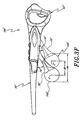
Figure 3F is a right side elevational view of the wearable audio device illustrated inFigure 3D . -
Figure 3G is a left side elevational view of the wearable audio device illustrated inFigure 3D . -
Figure 3H is a front elevational view of the wearable audio device illustrated inFigure 3D . -
Figure 3I is a top plan view of the wearable audio device illustrated inFigure 3D . -
Figure 3J is a front, top, and left side perspective and exploded view of the wearable audio device illustrated inFigure 3D . -
Figure 3K is an enlarged left side elevational view of one of the speakers of the audio device illustrated inFigure 3D . -
Figure 3L is an enlarged front elevational view of the speaker illustrated inFigure 3K -
Figure 3M is a schematic illustration of the audio device illustrated inFigure 3D . -
Figure 4A is a schematic representation of a rear and left side perspective view of a further modification of the wearable audio devices Illustrated inFigures 1, 2 , and3A-J . -
Figure 4B is a schematic representation of a partial sectional and left side elevational view of the wearable audio device illustrated inFigure 4A being worn a human. -
Figure 5A is a partial sectional and side elevational view of a modification of the wearable audio device illustrated inFigure 4A . -
Figure 5B is a partial sectional and side elevational view of a modification of the wearable audio device illustrated inFigure 5A . -
Figure 6 is a left side elevational view of a modification of the audio device illustrated inFigures 3-5 being worn on the head of a user. -
Figure 7 is a front elevational view of the audio device illustrated inFigure 6 . -
Figure 8 is a schematic representation of a front elevational view of a further modification of the audio device illustrated inFigures 1 and 2 being worn by a wearer and interacting with source electronics. -
Figure 9A is an enlarged schematic representation of a front elevational view of the audio device illustrated inFigure 8 . -
Figure 9B is a schematic representation of a left side elevational view of the audio device illustrated inFigure 9A . -
Figure 10 is a schematic left side elevational view of a modification of the audio device illustrated inFigures 8 and9A , B. -
Figure 11 is a front elevational view of the audio device illustrated inFigure 10 . -
Figure 12 is a top plan view of the audio device illustrated inFigure 10 . -
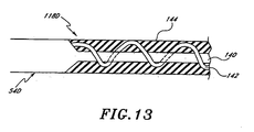
Figure 13 is a schematic representation of a partial cross-sectional view of a portion of any of the audio devices illustrated inFigures 1-12 . -
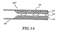
Figure 14 is a schematic representation of a partial cross-sectional view of a modification of the portion illustrated inFigure 13 . -
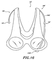
Figure 15 is a left side elevational view of a modification of the audio devices illustrated inFigures 8-12 . -
Figure 16 is a front elevational view of the audio device illustrated inFigure 15 . -
Figure 17 is a schematic illustration of communication hardware which can be incorporated into any of the wearable audio device as illustrated inFigures 1-16 and the communication hardware of another device. -
Figure 18 is a schematic representation showing three output signals, the uppermost signal being the output of a source device, and the lower signals being the representation of the output of an encoder/decoder device illustrated inFigure 17 . -
Figure 19 is a schematic illustration of the decoder illustrated inFigure 17 . -
Figure 20 is a schematic illustration of a modification of the decoder illustrated inFigure 19 , which can be incorporated into any of the wearable audio devices illustrated inFigures 1-16 . - The following items are preferred embodiments of the invention
- 1. A wearable wireless audio interface, comprising:
- a support configured to support at least one lens in a field of view of a wearer,
- interface electronics carried by the support and configured to output a first signal; and
- a transmitter configured to transmit a second readable signal not more than about 100 yards, the second signal corresponding to the first signal.
- 2. A wearable wireless audio interface as in item 1, wherein the support comprises a first and a second ear stem for positioning along the wearer's temples above the wearer's first and second ears.
- 3. A wearable wireless audio interface as in item 1, wherein the support comprises a pair of eyeglasses.
- 4. A wearable wireless audio interface as in item 1, wherein the transmitter is configured to transmit the second readable signal not more than about 30 feet.
- 5. A wearable wireless audio interface as in item 4, further comprising at least one microphone carried by the support.
- 6. A wearable wireless audio interface as in item 1, further comprising a receiver configured to receive a signal in the industrial Scientific Medical frequency band.
- 7. A wearable wireless audio interface as in item 1, further comprising a first speaker and a second speaker in communication with the interface electronics, and carried by the support such that they are positioned adjacent, but spaced apart from first and second ears of the wearer when the support is carried by the wearer, wherein the lateral distance between the center of the first speaker and the tragus of the first ear in the as worn orientation is within the range of from about 2 mm and about 3 cm.
- 8. A wearable wireless audio interface as in item 7 wherein the distance is at least about 4 mm.
- 9. A wearable wireless audio interface as in item 7 wherein the distance is within the range of from about 4 mm and about 2 cm.
- 10. A method of receiving a telephone call, comprising the steps of:
- wearing a wireless audio interface carried by an eyeglass frame, the eyeglass frame comprising at least a first speaker, a microphone, and a short range transceiver for communicating with a cellular telephone which is electronically paired with the transceiver,
- perceiving an incoming call on the cellular telephone; and
- activating the wireless interface to communicate with the cellular telephone.
- 11. A method of receiving a telephone call as in
item 10, wherein the activating step comprises activating a control carried by the eyeglass frame. - 12. A method of receiving a telephone call as in
item 10, wherein the perceiving step comprises perceiving an audible signal. - 13. A method of receiving a telephone call as in
item 10, wherein the perceiving step comprises perceiving a tactile signal. - 14. An audio interface system, comprising:
- a wireless audio interface; and
- source electronics, electronically paired with the wireless audio interface;
- wherein the interface comprises a first speaker and a second speaker carried by the interface such that in an as worn orientation on a wearer the first speaker is positioned adjacent but spaced apart from a first ear of the wearer and the second speaker is positioned adjacent but spaced apart from a second ear of the wearer, and wherein the wireless audio interface and the source electronics are configured to communicate wirelessly over a distance of no more than about 100 yards.
- 15. An audio interface system as in
item 14, wherein the source electronics comprises a source of music. - 16. An audio interface system as in item 15, wherein the source electronics comprises an MP3 player.
- 17. An audio interface system as in
item 14, wherein the source electronics comprises a cellular telephone. - 18. An audio interface system as in
item 14, wherein the source electronics comprises a wireless communication device. - 19. An audio interface system as in
item 14, wherein the interface electronics are capable of receiving a useful signal from the source electronics throughout a working range of no greater than about 70 yards. - 20. An audio interface system as in
item 14, wherein the interface electronics are capable of receiving a useful signal from the source electronics throughout a working range of no greater than about 30 - 21. An audio interface system as in
item 14, further comprising a control carried by the audio interface, for controlling the source electronics. - 22. An audio interface system as in item 21, wherein the control comprises an on - off control.
- 23. An audio interface system as in item 21, wherein the control comprises a send control.
- 24. An audio interface system as in item 21, wherein the control comprises a receive control.
- 25. An audio interface system as In
item 14, wherein the interface comprises a first support for carrying the first speaker and a second support for carrying the second speaker. - 26. An audio interface system as in item 25, wherein the first support is configured to extend along a first side of a wearer's head, and the second support is configured to extend along a second side of the wearer's head, to support the interface by the wearer's head.
- 27. An audio interface system as in
item 26, wherein the first speaker is offset laterally from the first support and the second speaker is offset laterally from the second support. - 28. An audio interface system as in
item 26, wherein the interface system comprises an eyeglass frame. - 29. An audio interface system as in
item 28, Further comprising a battery in at least one of the first and second supports. - 30. An audio interface system as in
item 28, further comprising a BLUETOOTH chip carried by the eyeglass frame. - 31. A method of manipulating a signal in a wireless personal network, comprising the steps of:
- providing source electronics within an effective range of the wireless personal network;
- providing an interface having at least one speaker, the interface configured to position the speaker adjacent the ear of a wearer;
- activating a control on the interface; and
- sending a signal from the source electronics to the speaker in response to the activating step.
- 32. A method of manipulating a signal in a wireless personal network as in item 31, wherein the interface comprises at least two speakers.
- 33. A method of manipulating a signal in a wireless personal network as in item 31, wherein the providing step comprises mounting the source electronics on the wearer.
- 34. A method of manipulating a signal in a wireless personal network as in item 31, wherein the providing step comprises providing a cellular telephone,
- 35. A method of manipulating a signal in a wireless personal network as in item 31, wherein the providing step comprises providing a music source.
- 36. A method of manipulating a signal in a wireless personal network as in item 35, wherein the providing step comprises providing an MP3 player.
- 37. A method of manipulating a signal in a wireless personal network as in item 31, further comprising the step of wirelessly communicating the signal from a remote transceiver to the source electronics.
- 38. An eyeglass frame, comprising:
- a support for supporting at least one lens in the path of a wearer's field of view;
- a first ear stem attached to the support, for extending in a posterior direction along a first side of the wearer's head;
- a second ear stem attached to the support, for extending in a posterior direction along a second side of the wearer's head;
- at least one microphone disposed in at least one of the support, first ear stem, and second ear stem, the microphone being arranged to face towards a head of a wearer of the eyeglass frame; and
- a transceiver supported by at least one of the support, the first ear stem, and the second ear stem, the transceiver being configured to wirelessly transmit a digital signal representative of an output of the microphone.
- 39. An eyeglass frame as in item 38, further comprising a baffle configured to attenuate wind turbulence in the vicinity of the microphone.
- 40. An eyeglass frame as in item 38, wherein said transceiver is positioned within at least one of the support, the first ear stem, and the second ear stem.
- 41. An eyeglass frame as in
item 40, wherein the transceiver is configured to transmit a readable signal no more than about twenty yards. - 42. An eyeglass frame as in item 38, wherein the microphone is configured to face upwardly and toward a head of a wearer.
- 43. An eyeglass frame as in item 38, wherein the microphone is configured to face horizontally and toward a head of a wearer.
- 44. An eyeglass frame as in item 38, wherein the microphone is configured to face downwardly and toward a head of a wearer.
- 45. An eyeglass frame as in item 38, wherein the microphone is supported on a lower edge of the support, below the lens.
- 46. An eyeglass frame as in item 38, wherein the support comprises a pair of orbitals supporting the at least one lens and a second lens, respectively, a bridge connecting the orbitals, the microphone being supported by the bridge.
- 47. An eyeglass frame as in
item 46, further comprising a wind sock disposed over the microphone. - 48. An eyeglass frame, comprising:
- a support including first and second orbitals supporting first and second lenses, respectively, and a bridge connecting the orbitals;
- a first ear stem attached to the support, for extending in a posterior direction along a first side of the wearer's head;
- a second ear stem attached to the support, for extending in a posterior direction along a second side of the wearer's head;
- at least one microphone supported by the bridge, the microphone being arranged to face away from a wearer of the eyeglass; and
- a wind sock disposed over the microphone.
- 49. An eyeglass frame as in
item 48, wherein the wind sock includes an outer surface shaped complimentarily to the bridge. - 50. An interactive audio device comprising:
- a support configured to be supported on a head of a human;
- a least one audio output device configured to output sound audible to a wearer of the audio device; and
- means for allowing a wearer of the audio device to browse an aural menu.
- 51. An audio device as in
item 50, wherein the aural menu comprises a plurality of stored humanoid voice sounds corresponding to functions supported by a source device which sends audio signals to the audio output device. - 52. An interactive audio device comprising:
- a support configured to be supported on a head of a human;
- a least one audio output device supported by the support and configured to output sound audible to a wearer of the audio device;
- at least one input device supported by the support and configured to accept inputs from a wearer of the audio device; and
- an interface device supported by the support, the interface device being configured to transmit aural menu options to the audio output device and to allow a user select a menu option through actuation of the input device.
- 53. An audio device as in
item 52, wherein the aural menu options comprise a plurality of stored humanoid voice sounds corresponding to functions supported by a source device which sends audio signals to the audio output device. - 54. An audio device as in
item 52, wherein input device is a microphone. - 55. An audio device as in
item 52, wherein input device is a button. - 56. An audio device as in
item 52, wherein the interface device is configured to transmit first signals corresponding to outputs of the input device to a second audio device, to receive second signals from the second audio device corresponding to aural menu options, and to transmit third signals to the audio output device corresponding to the second signals. - 57. A method of browsing through a menu comprising the steps of:
- wearing a wireless audio interface carried by an eyeglass frame, the eyeglass frame comprising at least a first speaker, a first input device, and a short range transceiver for communicating with a source device which is electronically paired with the transceiver;
- actuating the first input device;
- transmitting a first signal from the transceiver to the source device, the first signal corresponding to the actuation of the first input device;
- receiving a second signal from the source device in response to the first signal;
- transmitting a third signal corresponding to the second signal, from the transceiver to the first speaker, the third signal corresponding to a first aural menu option.
- 58. A method as in item 57, further comprising transmitting a fourth signal from the transceiver to the source device, the fourth signal corresponding to a further actuation of the first input device, receiving a fifth signal from the source device in response to the fourth signal, and transmitting a sixth signal corresponding to the fifth signal, from the transceiver to the first speaker, the sixth signal corresponding to a second aural menu option.
- 59. A method as in item 57, wherein the source device is a cellular telephone.
- 60. A method as in item 57, wherein the source device is a personal computer.
- 61. A method as in
item 60, wherein the source device is a laptop computer. - 62. A method as in item 57, wherein the source device is a palmtop computer.
- 63. An eyeglass includes a frame, at least one interactive electronic device supported by the frame, and at least one lens configured to have variable light attenuation.
- 64. An eyeglass in accordance with item 63, wherein the interactive electronics device comprises an audio interface for a cellular phone.
- 65. An eyeglass in accordance with item 63, wherein the interactive electronics device comprises a user operable switch supported by the frame and electronic device controlled by the switch.
- 66. An eyeglass in accordance with item 63, wherein the least one lens comprises a plurality of spaced substrates, a dichroic dye disposed between the substrates, and a first power source configured to alter an orientation of the dichroic dye.
- 67. An eyeglass in accordance with
item 66, wherein the frame comprises at least a first ear stem, the power source being disposed in the ear stem. - 68. An eyeglass in accordance with item 67 additionally comprising a second ear stem, at least a portion of the interactive electronic device being disposed in the second ear stem.
- 69. An eyeglass in accordance with
item 68 additionally comprising a second power source for powering the interactive electronic device disposed in the second ear stem, the first power source being disposed in the first ear stem. - 70. An eyeglass in accordance with
item 69 additionally comprising a first user operable switch disposed in the first ear stem and configured to control the first power source and the second user operable switch disposed in the second ear stem and configured to control the interactive electronic device. - 71. An eyeglass comprising a frame defining first and second orbitals, first and second lenses disposed in the first and second orbitals, respectively, first and second ear stems extending rearwardly from the frame, a compressed audio file storage and playback device disposed in the first ear stem, a power storage device disposed in the second ear stem, first and second speakers connected to the first and second ear stems, respectively, the speakers being configured to be alignable with an auditory canal of a wearer of the eyeglass.
- 72. The eyeglass according to
item 71 additionally comprising a first button disposed on the first ear stem, the first ear stem comprising a first upper surface facing a first direction and defining an aperture through which the first button extends and a lower surface facing a second direction generally opposite the first direction, the second surface having a width of at least about one-quarter of an inch. - 73. The eyeglass according to
item 72, wherein the width of the second surface is at least about one-half of an inch. - 74. The eyeglass according to
item 71 additionally comprising first and second speaker supports supporting the first and second speakers, respectively, relative to the first and second ear stems, respectively, the first and second supports extending from the ear stems at a predetermined angle. - 75. The eyeglass according to
item 74, wherein the predetermined angle is between about 30 degrees and 50 degrees. - 76. The eyeglass according to
item 74, wherein the predetermined angle is between about 35 degrees and 45 degrees. - 77. The eyeglass according to
item 74, wherein the predetermined angle is about 40 degrees. - 78. An eyeglass comprising a frame defining first and second orbitals, first and second lenses disposed in the first and second orbitals, respectively, first and second ear stems extending rearwardly from the frame, the first ear stem comprising an upper surface facing a first direction and including an aperture, a first button extending from the aperture, a lower surface below the upper surface and facing a second direction generally opposite the first direction, the lower surface having a width of at least one-quarter of an inch.
- 79. The eyeglass according to
item 78, wherein the width is measured in a direction transverse to a longitudinal direction of the ear stem. - 80. The eyeglass according to
item 79, wherein the width is at least about one-half of one-inch. - 81. An eyeglass comprising a frame, an electronic device disposed in the frame, at least one button exposed on an outer surface of the frame, and means for preventing loads from being transferred to the head of a wearer of the eyeglass when the button is depressed.
- 82. An eyeglass comprising a frame, at least one acoustic transducer supported by the frame for movement in at least first and second axes, and means for isolating movement of the transducer in the first axis from movement in the second axis.
- 83. A wearable wireless audio interface, comprising:
- a support comprising a first ear stem and an orbital, the support configured to support at least one lens in a wearer's field of view;
- a first earphone supported by the support, directed toward at least one of the wearer's ears, and configured to convert at least one received telecommunication signal into sound;
- a microphone supported by the support, and configured to convert the wearer's voice into at least one transmitted telecommunication signal;
- first electronics supported by the support and configured to receive the at least one received telecommunication signal; and
- second electronics supported by the support and configured to transmit the at least, one transmitted telecommunication signal.
- 84. A wearable wireless audio interface as in item 83, wherein the microphone is arranged to face towards the mouth of a wearer of the eyeglass frame.
- 85. A wearable wireless audio interface as in item 83. wherein the support comprises a pair of eyeglasses.
- 86. A wearable wireless audio interface as in item 85, wherein the pair of eyeglasses comprises a frame for supporting at least two lenses in the wearer's field of view.
- 87. A wearable wireless audio interface as in
item 86, further comprising a second microphone supported by the support - 88. A wearable wireless audio interface as in item 83, further comprising a second earphone supported by the support, directed toward at least one of the wearer's ears, and configured to convert a least one received telecommunication signal into sound.
- 89. An audio interface system, comprising:
- an eyeglass frame, comprising:
- a first earphone directed toward a wearer's ear,
- a first ear stem for supporting the first earphone;
- a second earphone directed toward a wearer's ear;
- a second ear stem for supporting the first earphone; and
- an orbital connected to at least one of the first ear stem and second ear stem and configured to support at least one lens in a wearer's field of view;
- receiver electronics supported by the eyeglass frame and configured to wirelessly receiver information; and
- source electronics electrically, coupled with the receiver electronics and configured to wirelessly transmit information to the receiver electronics.
- an eyeglass frame, comprising:
- 90. An audio interface system as in item 89, wherein the source electronics are configured to wirelessly receive information that the source electronics transmit to the receiver electronics.
- 91. An audio interface system as in
item 8, wherein the source electronics comprises a satellite. - 92. An audio interface system as in item 91, wherein the Satellite comprises a source of global positioning to determine the position of the wearer.
- 93. An audio interface system as in
item 90, wherein the source electronics comprises a source of music. - 94. An audio interface system as in item 91, wherein the source electronics comprises an MP3 player.
- 95. An audio interface system as in
item 90, wherein the receiver electronics is configured to receive telecommunications information. - 96. An eyeglass frame, comprising:
- a support for supporting at least one lens in the path of a wearer's field of view,
- a first ear stem attached to the support, for extending In a posterior direction along a first side of the wearer's head;
- a second ear stem attached to the support, for extending in a posterior direction along a second side of the wearer's head; and
- at least one microphone supported by at least one of the support, first ear stem, and second ear stem, the microphone being arranged to face towards the head of a wearer of the eyeglass frame.
- 97. An eyeglass frame as in
item 96, further comprising a power supply replaceably carried by the support - 98. An eyeglass frame as in
item 96, wherein the support comprises a pair of orbitals supporting the at least one lens and a second lens, respectively, a bridge connecting the orbitals, the microphone being supported by the bridge. - 99. An eyeglass, comprising:
- a frame configured to support a lens in the path of a wearer's field of view, the frame comprising:
- compassing; at least one orbital; and
- a first earphone support;
- a telecommunications receiver positioned inside of the frame;
- a telecommunications transmitter positioned inside of the frame;
- a first earphone carried by the first earphone support and
- a microphone carried by the frame.
- a frame configured to support a lens in the path of a wearer's field of view, the frame comprising:
- 100. An eyeglass as in item 99, further comprising a digital storage device.
- 101. An eyeglass as in
item 100, wherein the digital storage device comprises an MP3 storage device. - 102. An eyeglass as in item 99, further comprising a power supply carried by the frame.
- 103. An eyeglass as in
item 102, wherein the power supply is rechargeable. - 104. An eyeglass as in
item 102, wherein the power supply is replaceable carried by the frame. - 105. An eyeglass as in item 99, wherein the frame further comprises a second earphone and a second earphone support and wherein the second earphone is carried by the second earphone support.
- 106. An eyeglass as in item 105, wherein the first earphone support extends rearwardly from the front of the eyeglass and second earphone support extends rearwardly from the front of the eyeglass.
- 107. An eyeglass as in item 105, wherein the first earphone support extends down from the frame and second earphone support extends down from the frame.
- With reference to
Figures 1 and 2 , anaudio device 10 includes a support 12 and left andright speakers - The audio device 12 is illustrated as being supported on the
head 18 of a human. Thehead 18 includes anose 19, and left andright ears human ears Figure 2 , the meatus of the externalauditory canal 24 is illustrated schematically as a circle (in phantom) generally at the enter of theleft ear 20. - The support 12 is configured to be supported by the
head 18. Thus, the support 12 can be in the form of any known headwear. For example, but without limitation, the support 12 can be in the form of a hat, sweatband, tiara, helmet, headphones, and eyeglasses. - Advantageously, the support 12 is configured to support the
speakers ears ears speakers head 18 at a position other than the outer surface of theears Figure 1 , the support 12 is supported by thehead 18 by asupport portion 26 which contacts a portion of thehead 18 other than the outer surface of theears support 26 can contact the top of thehead 18, the sides of the head, top of thenose 19, forehead, occipital lobe, etc. - The
audio device 10 also includessupport members speakers support members speakers speakers ears - Optionally, the
support members speakers ears support members speakers ears speakers support members speakers ears - As noted above, the
speakers ears speakers ears speakers speakers ears - Comfort of the user is further enhanced if the support 12 is configured to maintain
gaps speakers ears ears gaps gaps speakers Figure 2 ). - Such a spacing can allow the support 12 to be removed and replaced onto the
head 18 of the user without rubbing against theears audio device 10 more convenient to use. - A modification of the
audio device 10 is illustrated inFigure 3A , and referred to generally by thereference numeral 10A. Components of theaudio device 10A that are the same as theaudio device 10 have been given the same reference numeral, except that a letter "A" has been added thereto. - In the illustrated embodiment of the
audio device 10A, thesupport 12A is in the form of aneyeglass 40. Theeyeglass 40 comprises aframe 42 which supports left andright lenses present audio device 10A will be described with reference to a dual lens eyeglass, it is to be understood that the methods and principles discussed herein are readily applicable to the production of frames for unitary lens eyeglass systems and projective goggle systems as well. Further, thelenses lenses support 12A. - Preferably, the
lenses lenses U.S. Patent No. 2,237,567 discloses iodine stained polarizers and is hereby expressly incorporated herein by reference. Additionally, rotatable lens designs are disclosed inU.S. Patent No. 4,149,780 , which is hereby expressly incorporated herein by reference. - Alternatively, the
lenses U.S. Patent Nos. 6,312,811 ,5,658,502 ,4,537,612 , each of which are hereby expressly incorporated by reference. - More preferably, the
lenses lenses frame 42. The power circuit is provided with a power supply connected to the conducting layers. Adjustment of the power supply alters the orientation of the host material which in turn alters the orientation of the dichroic dye. Light is absorbed by the dichroic dye, depending upon its orientation, and thus provides variable light attenuation. Such a dichroic dye guest-host device is disclosed inU.S. Patent No. 6,239,778 , which is hereby expressly incorporated by reference. - The
frame 42 also comprises left andright orbitals right lenses orbitals respective lenses orbitals bridge portion 52. - The
eyeglass 40 is also provided with a pair of generally rearwardly extending ear stems 54, 56 configured to retain theeyeglass 40 on the head of a wearer. In addition, anopen region 58 is configured to receive the nose of the wearer, as is understood in the art. Theopen region 58 may optionally be provided with a nose piece, either connected to thelens orbitals bridge 52, or directly to the lenses, depending on the particular embodiment. Alternatively, the nose piece may be formed by appropriately sculpting the medial edges of theorbitals bridge 52, as in the illustrated embodiment. - The
frame 42 and the ear stems 54, 56 can be made from any appropriate material, including polymers and metals. Preferably, theframe 42 and the ear stems 54, 56 are manufactured from a polymer. Theorbitals bridge 52, or theorbitals bridge 52 can be integrally molded or cast. When a metal material is used, casting the eyeglass components directly into the final configuration desirably eliminates the need to bend metal parts. - The ear stems 54, 56 are pivotally connected to the
frame 42 withhinges portions padded portions 64; 66 preferably are positioned such that when theaudio device 10A is worn by a wearer, the paddedportions - In the illustrated embodiment, the
support members support arms speakers ears 20, 22 (Figure 1 ) of a wearer'shead 18. In particular, because theeyeglass 40 is generally supported at three positions, the alignment of thespeakers ears eyeglass 40 is supported at the left ear stem in the vicinity of theleft ear 20, at thebridge 52 by a portion of the user's head in the vicinity of thenose 19, and at theright ear stem 56 by a portion of the user'shead 18 in the vicinity of theear 22. - Optionally, the
support arms spacing speakers ears speakers ears eyeglass 40. - Further, the
support arms support arms support arms speakers ears support arm speakers ears Figures 3D-J . - With the configuration shown in
Figure 3A , theaudio device 10A maintains thespeakers ears audio device 10A. - Preferably, the
support arms support arms support arm support arms support arms - Alternatively, the
support arm ears eyeglass 40 is worn by a user. As such, thesupport arms speakers eyeglass 40 such that thelenses speakers ears - Preferably, the
support arm angles angles angles angles angles angles - Optionally, the
support arm angles support arm speakers - The
audio device 10A can be used as an audio output device for any type of device which provides an audio output signal. Theaudio device 10A can include an audio input terminal disposed anywhere on theeyeglass 40 for receiving a digital or analog audio signal. Preferably, wires connecting the input jack (not shown) with thespeakers eyeglass 40. Alternatively, theaudio device 10A can include a wireless transceiver for receiving digital signals from another device. - With reference to
Figures 3D-3J , a modification of theaudio devices reference numeral 10A'. Theaudio device 10A' can include the same components as theaudio devices audio device 10A that are similar to the corresponding components of theaudio devices - The
audio device 10A' is in the form of aneyeglass 12A' having aframe 40A'. Theaudio device 10A' also includes a device for the storage and playback of a sound recording. - As noted above, an aspect of at least one of the inventions disclosed herein includes a realization that the forward to rearward spacing of the bridge of a human nose to the auditory canal of the ear falls into a relatively narrow range of distances for large portions of the population. For example, the forward-to-rearward spacing from the bridge of the nose to the auditory canal is normally between about 4 7/8 inches to about 5 1/8 inches, and often between about 4 ¾ inches and about 5 1/4 inches. Corresponding anterior-posterior plane adjustability of the speakers is preferably provided.
- Thus, with reference to
Figure 3F , theaudio device 10A' is configured such that the supports 68', 78', can translate, along a forward to rearward direction, over a range identified generally by the reference numeral Rt. Preferably, the range Rt is at least about 1/8 of one inch. Further, the range Rt can be at least about % of one inch. Further, the range Rt can be in the range of from about 0.25 inches to about 1.5 inches, and, in one construction, is about 0.75 of one inch. As such, a substantial percentage of the human population will be able to align a Center of thespeakers 14A', 16A' with their auditory canal. - With reference to
Figure 3G , a further advantage is provided where the diameter Ds of thespeakers 14A', 16A' is greater than about 0.5 inches, such as about 1 inch or greater. As such, an effective range Re (Figure 3F ) over which thespeakers 14A', 16A' can reach, is significantly enhanced with respect to the above-noted nose bridge to auditory canal spacings for humans. - Thus, the connection between the supports 68', 70' to the ear stems 54', 56', respectively, can be configured to allow a limited translational range of movement of Rt yet provide a larger range of coverage Re.
- Preferably, the connection between the support 68', 70' and the ear stems 54', 56', is configured such that the translational position of the
speakers 14A',16A' is maintained when a user removes theaudio device 10A' from their head. For example, the connection between the supports 68', 70', and the ear stems 54', 56' can generate sufficient friction so as to resist movement due to the weight of the supports 68', 70' and thespeakers 14A', 16A'. Alternatively, the connection or an adjustment device can include locks, clips, or other structures to prevent unwanted translational movement of thespeakers 14A', 16A'. As such, a further advantage is provided in that a user can repeatedly remove and replace theaudio device 10A' without having to readjust the translational position of thespeakers 14A', 16A'. - Another advantage is provided where the supports 68', 70' are made from a material that is substantially rigid, at least at room temperature. For example, with reference to
Figure 3F , the angles 72', 74' defined between the supports 68', 70' and the ear stems 54', 56', respectively, can be maintained at a predetermined value while thespeakers 14A', 16A' can be moved over the range Rt. Thus, as noted above with reference toFigure 3A and the description of theangles speakers 14A',16A' over the range Rt. - Optionally, the supports 68'; 70' can be made from a material that can be deformed at room temperature. However, more preferably the material is sufficiently rigid such that substantial pressure is required to change the angle 74'. Alternatively, the supports 68', 70' can be made from a thermally sensitive material that can be softened with the application of heat. Thus, a wearer of the
audio device 10A' can heat the supports 68', 70' and adjust the angle 74' to optimize comfort for the particular wearer. Such thermal sensitive materials are widely used in the eyewear industry and thus a further description of such materials is not deemed necessary for one of ordinary skill in the art to make and use the inventions disclosed herein. Preferably, the angles 72'; 74' are sized such that the spacing Vs between the center C of thespeakers 14A', 16A' and a lower surface of the ear stems 54', 56' is within the range of about 0.75 of an inch to about 1.25 inches. One aspect of at least one of the inventions disclosed herein includes the realization that there is little variation in the spacing for adult humans between the center of the auditory canal and the connecting tissue between the pinna of the ear and the skin on the side of the head. In particular, it has been found that in virtually all humans, the distance between the upper most connection of the ear and the head to the center of the auditory canal is between 0.75 of an inch and 1.25 inches. Thus, by sizing the angles 72', 74' such the spacing Vs is between about 0.75 of an inch and 1.25 inches, theaudio device 10A can be worn by virtually any adult human and has sufficient alignment between the wearer's auditory canal and the center C of thespeakers 14A', 16A'. Further, where the diameter Ds of thespeakers 14A', 16A' is about 1 inch, almost any human can wear theaudio device 10A' without having to adjust the angles 72', 74'. In other words, the auditory canal of virtually any human would be aligned with a portion of thespeakers 14A', 16A' although the wearer's auditory canal might not be precisely aligned with the center C of thespeakers 14A', 16A'. - With reference to
Figure 3H , the supports 68', 70' are configured to allow thespeakers 14A', 16A', respectively, to pivot toward and away from an ear of a user. For example, as shown inFigure 3H , the supports 68', 70' are connected to the ear stems 54', 56', respectively, so as to be pivotable about a pivot axis P. As such, thespeakers 14A',16A' can be pivoted or swung about the pivot axis P. - The range of motion provided by the connection between the supports 68', 70' and the ear stems 54', 56' is identified by the angle S in
Figure 3H . InFigure 3H , thespeaker 14A' is illustrated in an intermediate position in the range of motion provided by the connection between the support 68' and the ear stem 54'. - The illustration of the
speaker 16A' includes a solid line representation showing a maximum outward position of thespeaker 16A'. Additionally,Figure 3H includes a phantom illustration of thespeaker 16A' in a maximum inward position. The angle S illustrates a range of motion between a maximum outward position (solid line) and a maximum inward position (phantom line) of thespeaker 16A'. - Preferably, the range of motion S is sufficiently large to allow any human wearer of the
audio device 10A' to position thespeakers 14A', 16A' such that sound emitted from thespeakers 14A', 16A' is clearly audible yet comfortable for the wearer of theaudio device 10A'. For example, human ears vary in the precise shape and size of the outwardly facing features. As such, one wearer of theaudio device 10A' may have outer facing features of their ear that project further than another wearer of theaudio device 10A'. Thus, one wearer may prefer thespeakers 14A', 16A' to be positioned more inwardly than another wearer. - Further, some wearers of the
audio device 10A' may prefer to press thespeakers 14A', 16A' into contact with the outer surfaces of their ears. For example, some users may desire to experience to loudest possible volume from thespeakers 14A', 16A'. Thus, by pressing thespeakers 14A', 16A' against their ears, the perceived volume of the sound emitted from thespeakers 14A', 16A' will be the greatest. - Alternatively, other users may prefer to have the speakers spaced from the outer surfaces of their ear so as to prevent contact with the ear, yet maintain a close spacing to preserve the perceived volume of the sound emitted from the
speakers 14A', 16A'. Additionally, a user may occasional wish to move thespeakers 14A', 16A' further away from their ears, so as to allow the wearer better hear other ambient sounds when thespeakers 14A', 16A' are not operating. For example, a wearer of theaudio device 10A' might wish to use a cellular phone while wearing theaudio device 10A'. Thus, the wearer can pivot one of thespeakers 14A', 16A' to a maximum outward position (e.g., the solid line illustration ofspeaker 16A' inFigure 3H ) to allow a speaker of the cell phone to be inserted in the space between thespeaker 16A' and the ear of the wearer. As such, the wearer can continue to wear theaudio device 10A' and use another audio device, such as a cell phone. This provides a further advantage in that, because theaudio device 10A' is in the form ofeyeglasses 12A', which may include prescription lenses or tinted lenses, the wearer of theaudio device 10A' can continue to receive the benefits of such tinted or prescription lenses while using the other audio device. - An additional advantage is provided where the pivotal movement of the supports 68', 70' is isolated from the translational movement thereof. For example, the connection between the supports 68', 70' and the ear stems 54', 56' can be configured so as to allow a user to pivot the supports 68', 70' without substantially translating the supports 68', 70' forwardly or rearwardly. In one embodiment, the connections can be configured to provide more perceived frictional resistance against translational movement than the frictional resistance against pivotal movement about the pivot axis P (
Figure 3H ). Thus, a user can easily pivot thespeakers 14A', 16A' toward and away from their ears without translating thespeakers 14A', 16A'. Thus, the procedure for moving thespeakers 14A', 16A' toward and away from a wearer's ears can be performed more easily and, advantageously, with one hand. - The range of motion S is generally no greater than about 180°, and often less than about 90°. In one preferred embodiment, the range of motion S is no more than about 30° or 40°. The connection between the support 68', 70' and the ear stems 54', 56', respectively, is generally configured to provide a sufficient holding force for maintaining a rotational orientation of the
speakers 14A', 16A' about the pivot axis P. For example, the connection between the supports 68', 70' and the ear stems 54', 56', respectively, can be configured to generate sufficient friction to resist the forces generated by normal movements of a wearer's head. - A further advantage is achieved where sufficient friction is generated to prevent the pivotal movement of the
speakers 14A', 16A' when theaudio device 10A' is removed from the wearer and placed on a surface such that thespeakers 14A', 16A' support at least some of the weight of theaudio device 10A'. For example, when a wearer of theaudio device 10A' removes theaudio device 10A' and places it on a table with thespeakers 14A', 16A' facing downwardly, thespeakers 14A',16A' would support at least some of the weight of theaudio device 10A'. Thus, by providing sufficient friction in the connection between the supports 68', 70' and the ear stems 54', 56', respectively, the position of thespeakers 14A', 16A' can be maintained. Thus; when the wearer replaces theaudio device 10A', thespeakers 14A', 16A' will be in the same position, thereby avoiding the need for the wearer to repositionspeakers 14A', 16A'. - As noted above, an aspect of one of the inventions disclosed herein includes the realization that where an electronic device that is worn in the same manner as a pair of eyeglasses includes a user operable switch for controlling a function of the electronics, the comfort of the wearer of the audio device can be enhanced where the switches are operable without transferring a substantial load to the head of the wearer. For example, where the electronic device includes buttons for controlling an aspect of the device, a further advantage is provided where a support surface is provided opposite the button such that a user can apply a balancing force to the actuation force applied to the button, thereby preventing a substantial force from being transferred to the head of the wearer.
- With reference to
Figure 3I , theaudio device 10A' can include at least onebutton 73a. In the illustrated embodiment, theaudio device 10A' includes five buttons; afirst button 73a and asecond button 73b mounted to the left ear stem 54', and athird button 73c, afourth button 73d, and afifth button 73e mounted to the right ear stem 56'. Of course, this is one preferred embodiment of the arrangement of thebuttons - As shown in
Figure 3H , thebutton 73a is mounted on an upwardly facing surface of the ear stem 54'. Additionally, the ear stem 54' has a lower surface that faces in a generally opposite direction to the direction towards which the upper surface of the ear stem 54' faces. Thus, as shown inFigure 3H , the user can use afinger 71 to actuate thebutton 73a and athumb 69 to counteract the actuation force of thefinger 71 by pressing on the lower surface of the ear stem 54'. As such, the wearer or user of theaudio device 10A' can actuate thebutton 73a without imparting a substantial load to the wearer of theaudio device 10A'. - This provides a further advantage in that a repeated application of a force against the
audio device 10A' that is transferred to the head of the wearer of theaudio device 10A' is avoided. For example, where the audio 10A' is in the form ofeyeglasses 12A', a wearer of theeyeglasses 12A' can be subjected to irritations if the wearer repeatedly presses the eyeglasses 1.2A' to actuate a switch. Further, such repeated loads can cause headaches. Thus, by configuring the ear stems 54A' such that thebutton 73a can be depressed without transferring a substantial load to the wearer of theear glasses 12A', such irritations and headaches can be avoided. - Further, by disposing the
button 73a on an upper portion of the ear stems 54A', and by providing the ear stems 54A' with an opposite lower surface that faces an opposite direction relative to the upper surface, a wearer can grasp the ear stems 54A' from the side, as illustrated inFigure 3B , thereby allowing the user to counteract the actuation force required to actuate thebutton 73a without having to insert a finger between a side of the wearer's head and ear stems 54A'. -
Figure 3J illustrates an exemplary embodiment of theaudio device 10A. As shown inFigure 3J , the left side ear stem 54A' defines anelectronic housing portion 250 which defines aninternal cavity 252 configured to receive electronic components. Theelectronics housing 250 includes anupper surface 254 andlower surface 256. Theupper surface 254 extends generally outwardly from the ear stems 54A' and around theinternal cavity 252. The upper surface also includesapertures button - The
housing 250 includes alower surface 260. The lower surface 260 (which may contain apertures or slots) faces in an opposite direction from theupper surface 254 of thehousing 250. Preferably, thelower surface 260 is at least about 0.5 inches, and may be 0.75 inches or more wide. As such, thelower surface 260 provides a surface which allows a wearer to easily grasp the ear stems 54A' so as to balance an actuation force supplied to thebutton - A
cover member 262 cooperates with thehousing 250 to define the closedinternal cavity 252. In the illustrated embodiment, theinternal cavity 252 includes at least one compartment configured to receive anelectronic circuit board 264 which includes at least one switch for each of thebuttons board 264 can include two switches, one for each of thebuttons speakers 14A', 16A'. Thecover 262 can be attached to the ear stems 54A' with any type of fastener, such as, for example, but without limitation, screws, rivets, bolts, adhesive, and the like. - In the illustrated embodiment, the
housing 250 also defines ahinge recess 262. Additionally, thecover member 262 includes acomplimentary hinge recess 268. Therecesses hinge pin 270. In the illustrated embodiment, thehinge pin 270 is hollow and includes an aperture therethrough. The ends of thehinge pin 270 are configured to be engaged with corresponding portions of the frame 42' so as to anchor the position of thehinge pin 270 relative to the frame 42'. When thecover 262 is attached to thehousing 250, with thehinge pin 270 disposed in therecesses hinge pin 270 provides a passage through which electrical conduits can pass, described in greater detail below. - The
housing 250 also includes a power source recess (not shown). The power source recess includes an opening 272 sized to receive apower storage device 274. In the illustrated embodiment, thepower storage device 274 is in the form of an AAAA-sized battery. Of course, thepower storage device 274 can be in the form of any type or any size of battery and can have any shape. However, a further advantage is provided where a standard-sized battery such as an AAAA battery is used. For example, as described in greater detail below, this size battery can be conveniently balanced with other electronic components configured for playback of a sound recording. - A
door 276 is configured to close the opening 272. In the illustrated embodiment, thedoor 276 is preferably hingedly connected to ahousing 250 so as to allow the door to be rotated between an open position and a closed position.Figures 3D-3I illustrate thedoor 276 in a closed position. - The ear stem 56' includes a
housing 280 defining aninternal cavity 282 configured to receive at least one electronic component. Thehousing 280 also includes upper and lower surfaces (unnumbered) that can be configured identically or similarly to the upper andlower surfaces housing 250. However, in the illustrated embodiment, the upper surface of thehousing 280 includes 3 apertures configured to receive portions of thebuttons housing 280 is not necessary for one of ordinary skill in the art to make and use the inventions disclosed herein. - The
internal cavity 282, in the illustrated embodiment, is configured to receive a printedcircuit board 284. In the illustrated embodiment, the printedcircuit board 284 includes one switch for each of thebuttons circuit board 284 includes an audio file storage andplayback device 286. - The
device 286 can be configured to store and playback any type of electronic audio and/or video file. In the illustrated embodiment, thedevice 286 includes a memory, an amplifier, and a processor. The memory, amplifier, and the processor are configured to operate together to function as an audio storage and playback system. For example, the audio storage and playback system can be configured to store MP3 files in a memory and to play back the MP3 files through thespeakers 14A', 16A'. Suitable electronics for enabling and amplifying MP3 storage and playback are well known in the art, and may be commercially available from Sigmatel, Inc. or Atmel, Inc. Thus, further description of the hardware and software for operating thedevice 286 as a storage and playback device is not necessary for one of ordinary skill in the art to make and use the inventions disclosed herein. - Advantageously, the printed
circuit board 284 also includes or is in electrical communication with a data transfer port 388. In the illustrated embodiment, thehousing 280 includes an aperture (not shown) disposed in a position similar to the position of the aperture 272 on thehousing 250. In thehousing 280, however, the aperture is aligned with thedata transfer port 288. Thus, when the printedcircuit board 284 is received in theinternal cavity 282, thedata transfer port 288 is aligned with the aperture. - A
door 290 is configured to open and close the aperture through which thedata port 288 is exposed. Preferably, thedoor 290 is hingedly engaged to thehousing 280, in an identical or similar manner as thedoor 276. In the illustrated embodiment, thedoor 290 can be pivoted relative tohousing 280, thereby exposing thedata transfer port 288. In the illustrated embodiment, the data transfer port is configured to operate according to the universal serial bus (USB) transfer protocol. Optical data ports may alternatively be used. As a further alternative, MP3 files may be uploaded from a source using wireless systems, such as BLUETOOTH® protocols, as is discussed below. Further, thedevice 286 is configured to receive audio files from another computer, through thedata transfer port 288 and to store the files into the memory incorporated into thedevice 286. - A
cover 292 is configured to close theinternal cavity 282. Thecover 292 can be configured in accordance with the description of thecover 262. Similarly to thehousing 250 and cover 262, thehousing 280 and cover 292 includerecesses hinge pin 298. Thehinge pin 298 can be constructed identically or similarly to thehinge pin 270. Thus, with thehinge pin 298 engaged with a frame 42', thecover member 292 can be attached to thehousing 280 with thehinge pin 298 received within therecesses - With continued reference to
Figure 3J , thespeakers 14A', 16A' can be constructed in a similar manner, as a mirror image of each other. Each of thespeakers 14A', 16A', include ahousing member 300. Eachhousing member 300 includes atransducer housing 302, asupport stem 304, and aguide portion 306. - The
transducer housing portion 302 includes an internal recess 308 (identified in the illustration ofspeaker 16A'). Thetransducer recess 308 can be sized to receive any type of acoustic transducer. For example, but without limitation, thetransducer recess 308 can be configured to receive a standard acoustic speaker commonly used for headphones. In a non-limiting embodiment, the speaker transducer (not shown) has an outer diameter of at least about 0.6 inches. However, this is merely exemplary, and other sizes of transducers can be used. - With reference to the illustration of the
speaker 14A', thesupport stem 304 connects thetransducer housing 302 with theguide portion 306. Thesupport stem 304 includes an aperture therethrough (not shown) which connects thetransducer recess 308 with theguide portion 306. - The
guide portion 306 includes anaperture 310 which communicates with the aperture extending through thesupport stem 304. Thus, an electric conduit, described in greater detail below, can extend through theaperture 310, through thestem 304, and then to thetransducer recess 308. - The
guide portion 306 also includes aguide aperture 312. Theguide aperture 312 is configured to receive aguide pin 314. - The
guide pin 314 can be made from any material. In the illustrated embodiment, theguide pin 314 is a rod having an outer diameter of about 0.0625 of an inch. When assembled, theguide pin 314 is disposed within an open recess (not shown) disposed on an under surface of thehousing 250. Theaperture 312 is sized so as to slidably receive thepin 314. Thus, theguide portion 306 can translate relative to thepin 314 as well as rotate relative to thepin 314. The size of theaperture 312 can be configured to provide a slip fit with sufficient friction to provide the stable positions noted above with reference toFigures 3D-3I . - In this embodiment, the
guide pin 314 and theaperture 312 provide both translational and pivotal movement. Additionally, theguide pin 314 and theaperture 312 can be configured to resistance to both translational movement and pivotal movement, with the resistance to translational movement being greater. For example, the axial length and diameter of theaperture 312, controls the maximum contact area between theguide pin 314 and theguide portion 306 and thus affects the frictional force generated therebetween. Thus, the length and diameter of theaperture 312 can be adjusted to achieve the desired frictional forces. - Additionally, with reference to
Figure 3K , when a translational force X is applied to the speaker 14at a torque T is created, which results in reaction forces Xr urging theguide portion 306 against theguide pin 314 at the forward and rearward ends thereof. These reaction forces Xr increase the frictional resistance against the translational movement of thespeaker 14A'. However, as shown inFigure 3L , when a pivot force θ is applied to thespeaker 14A', such reaction forces are not created, and thespeaker 14A' can pivot about theguide pin 314 with seemingly less force applied as compared to the force X required to move thespeaker 14A' in a direction parallel to theguide pin 314. - With reference again to
Figure 3J , the recess on the lower surface of thehousings guide portion 306 to slide in a forward to rearward direction in the range Rt, described above with reference toFigure 3F . Additionally, the open recess on the lower surface of thehousings speakers 14A', 16A', described above with reference toFigure 3H . - With reference to
Figure 3E , the frame 42' includes an interiorelectrical conduit channel 316 configured to receive an electrical conduit for connecting the speakers 14', 16', the printedcircuit boards power storage device 274. For example, with reference toFigure 3M , thebuttons device 286 through conduits 73ai, 73bi. Thestorage device 274 is connected to thedevice 286 through apower line 274i. Additionally, thespeaker 14A' is connected to thedevice 286 with an audio output conduit 14Ai'. - As illustrated in
Figure 3M , portions of.the conduits 73ai, 73bi, 274i and 14Ai', extend through thechannel 316. In an exemplary embodiment, the conduits 73ai, 73bi, 274i, and 14Ai', can be in the form of aribbon connector 318 extending through thechannel 316. Thus, with reference toFigures 3J and3M , theribbon connector 318 can extend from thehousing 280, into therecesses hinge pin 298 to the upper opening within thehinge pin 298, then through the channel 316 (Figure 3E ), to an upper opening of thehinge pin 270, out through an aperture (not shown) through a side of ahinge pin 270, through therecesses housing 250, and then to thespeaker 14A', printedcircuit board 264, and thepower storage device 274. - The
conduit 14A' can extend to theaperture 310 in theguide portion 306, through a central aperture of thesupport stem 304, and into thetransducer recess 308, as to connect to a transducer disposed therein. Optionally, the portion of the conduit 14Ai' that extends out of thehousing 250 and into thetransducer housing 300 can be formed from an insulated metal conduit, or any other known conduit. Thespeaker 16A' can be connected to the printedcircuit board 284 in a similar manner. - The
buttons data transfer port 288 are connected to thedevice 286 through printed conduits incorporated into the printedcircuit board 284. - As noted above, one aspect of at least one of the inventions disclosed herein includes the realization that a desirable balance can be achieved by disposing a power storage device in one ear stem of an eyeglass and play-back device into the second ear stem, Thus, as illustrated in
Figures 3J and3K , thepower storage device 274 is disposed in the left ear stem 54' and the storage and play-back device 286 is disposed in the right ear stem 56'. - In the illustrated embodiment, the
buttons speakers 14A', 16A'. For example, thebutton 73a can be used for increasing volume and thebutton 73b can be used for decreasing volume. Alternatively, thebutton 73b can be for increasing volume and thebutton 73a can be for decreasing volume. When a wearer of theaudio device 10A' presses one of thebuttons device 286. Thedevice 286 can be configured to interpret the on-off signals from thebuttons speakers 14A', 16A' accordingly. - Optionally, a third command can be generated by pressing both of the
buttons device 286 can be configured to interpret simultaneous signals from both thebuttons speakers 14A', 16A'. Of course, other functions can be associated with thebuttons - The
buttons device 286 similarly to thebuttons button 73c corresponds to a power button. For example, thedevice 286 can be configured to recognize a signal from thebutton 73c as a power on or power off request. In this embodiment, when thedevice 286 is off, and a signal from thebutton 73c is received, thedevice 286 can turn on. Additionally, thedevice 286, when in an on state, can be configured to turn off when a signal from thebutton 73c is received. Optionally, thedevice 286 can be configured to, when in an off or standby state, turn on and begin to play an audio file when a signal from thebutton 73c is received. Additionally, thedevice 286 can be configured to pause when another signal from thebutton 73c is received. In this embodiment, thedevice 286 can be configured to turn off only if thebutton 73c is held down for a predetermined amount of time. For example, thedevice 286 can be configured to turn off if thebutton 73c is held down for more than two seconds or for three seconds or for other periods of time. - The
buttons button 73d can correspond to a track skip function. In an illustrative but non-limiting example, such a track skip function can cause thedevice 286 to skip to a next audio file in the memory of thedevice 286. Similarly, thebutton 73e can correspond to a reverse track skip function in which thedevice 286 skips to the previous audio file. - Optionally, the
buttons device 286 can be configured to fast forward through an audio file, and play the corresponding sounds at a fast forward speed, when thebutton 73d is held down and to stop and play the normal speed when thebutton 73d is released. Similarly, thedevice 286 can be configured to play an audio file backwards at an elevated speed, when thebutton 73e is held down, and to resume normal forward play when thebutton 73e is released. This arrangement of thebuttons buttons - With reference to
Figures 4A-4B , a modification of theaudio devices reference numeral 10A". Theaudio device 10A" can include the same components as theaudio devices audio device 10A" that are similar to corresponding components of theaudio devices - The
audio device 10A" is in the form of aeyeglass 12A" having aframe 40A". Theaudio device 10A" also includes at least onemicrophone 75. Advantageously, themicrophone 75 is disposed so as to face toward the wearer. -
Figure 4B illustrates a partial cross-sectional view of theeyeglass 12A" on thehead 18 of a wearer. Themicrophone 75 is schematically illustrated and includes atransducer unit 76. In the illustrated embodiment,'thetransducer 76 is disposed within theframe 40A" and at least oneaperture 77 extends from thetransducer unit 76 to the outer surface of theframe 40A". Alternatively, the transducer can be positioned so as to be exposed on the outer surface of theframe 40A". - Advantageously, the
aperture 77 is disposed so as to face toward the head of theuser 18. The illustratedaperture 77 faces downward and toward thehead 18 of the wearer. By configuring the aperture to extend downwardly and toward thehead 18, the aperture is disposed as close as possible to the mouth of the wearer while benefiting from the wind protection provided by positioning theaperture 77 on the portion of theframe 40A' facing towards thehead 18. - Alternatively, the aperture can be positioned so as to extend generally horizontally from the
transducer 76 to an outer surface of theframe 40A", this configuration being illustrated and identified by the numeral 78: By configuring theaperture 78 to extending generally horizontally toward thehead 18, theaperture 78 is better protected from wind. - As another alternative, the aperture can be configured to extend upwardly from the transducer and toward the
head 18, this configuration being identified by the numeral 79. By configuring theaperture 79 to extend upwardly from thetransducer 76 and toward thehead 18, theaperture 79 is further protected from wind which can cause noise. However, in this orientation, theaperture 79 is more likely to collect water that may inadvertently splash onto theaperture 79. Thus, the aperture configuration identified by the numeral 77 provides a further advantage in that water is less likely to enter theaperture 77. Any water that may enter theaperture 77 will drain therefrom due to gravity - The
microphone 75 can be disposed anywhere on theframe 40A', including theorbitals 48A". 50A", thebridge 52A", or the ear stems 54A", 56A". Optionally, themicrophone 75 can be in the form of a bone conduction microphone. As such, themicrophone 75 is disposed such that the when a user wears theaudio device 10A', themicrophone 75 is in contact with the user'shead 18. For example, but without limitation, the microphone can be positioned anywhere on the anywhere on theframe 40A', including theorbitals 48A". 50A", thebridge 52A", or the ear stems 54A", 56A" such that the microphone contacts the user's head. More preferably, themicrophone 75 is positioned such that it contacts a portion of the user'shead 18 near a bone, such that vibrations generated from the user's voice and traveling through the bone, are conducted to the microphone. In another alternative, themicrophone 75 can be configured to be inserted into the meatus 24 (Figure 2 ) of the ear canal of the user. Thus, in this modification, themicrophone 75 can be substituted for one of thespeakers - Further, the
audio device 10A" can include noise cancellation electronics (not shown) configured to filter wind-generated noise from an audio signal transmitted from themicrophone 75. -
Figure 5A illustrates a modification in which themicrophone 75 is disposed on thebridge 52A". Similarly to the configuration illustrated inFigure 4B , thebridge 52A" can include anaperture 77 which extends downwardly and toward thenose 19 of the wearer, horizontally extendingaperture 78, or an upwardly extendingaperture 79. - Alternatively, the
microphone 75 can include a forwardly facing aperture, as illustrated inFigure 5B , and awind sock 81 disposed over the aperture. Thewind sock 81 can be made in any known manner. For example, thewind sock 81 can be made from a shaped piece of expanded foam. Configuring thebridge portion 52A' as such is particularly advantageous because the bridge portion of an eyeglass is typically somewhat bulbous. A wind sock can be shaped complementarity to thebridge portion 52A'. Thus, thesock 81 can be made so as to appear to be part of a normal bridge portion of an eyeglass. - The
audio device 10A" can include electrical conduits extending through theframe 40A" to an audio output jack (not shown). The audio output jack can be disposed at the end of the ear stems 54A", 56A", or anywhere else on theframe 40A". Thus, a user can wear theaudio device 10A' and use themicrophone 75 in order to transform the voice of the wearer or other sounds into an electrical signal. The electrical signal can be transmitted to another audio device, such as a palm top computer, a laptop computer, a digital or analog audio recorder, a cell phone, and the like. Additionally, theaudio device 10A° can include speakers, such as thespeakers 14A", 16A" illustrated inFigure 3A . As such, theaudio device 10A" can be configured to provide two-way audio for the wearer, i.e., audio input being transmitted to the user through thespeakers 14A", 16A", and audio output being transmitted from the wearer, through themicrophone 75, and out through the audio output jack. As such, a user can use theaudio device 10A" for two-way audio communication in a comfortable manner. - With reference to
Figures 6 and7 , a modification of theaudio devices reference numeral 10B. Components of theaudio device 10B corresponding to components of theaudio devices - The
audio device 10B is in the form of aneyeglass 80. Theeyeglass 80 includes aframe 82. Theframe 82 includes left andright orbitals orbitals lens frame 82 also includes abridge portion 92. Similarly to thebridge portion 52 of theaudio device 10A, thebridge portion 92 connects theorbitals bridge portion 92 defines anopen space 94 configured to receive thenose 19 of a wearer. The inner sides of theorbitals bridge portion 92 is configured to support theframes 82 on the nose of a user. - The
eyeglass 80 also includes support stems 96, 98 extending from the upper portions of theorbitals bridge portion 92, support theeyeglass 80 on thewearers head 18. Thesupport members support arms - With reference to
Figures 5 ,6 and7 , thesupport arms support arms support arm 100 extends from thestem 96 to a point just forward from the tragus of the user'sear 20. From this point, thesupport arm 100 extends rearwardly so as to support thespeaker 14B at a position juxtaposed and spaced from theear 20. Preferably, thespeaker 14B is maintained in a position from about 2 mm to 3 cm from the tragus of theear 20. Similarly to theaudio device 10A, theaudio device 10B can include an audio input through a wired arrangement or through a wireless transceiver. - With reference to
Figures 8 ,9A, and 9B , another modification of theaudio device 10 is illustrated therein and referred to generally by the reference numeral 10C. Similar components of the audio device 10C have been given the same reference numerals, except that that a "C" has been added thereto. - As illustrated in
Figure 8 , the audio device 10C can be worn on thehead 18 of a user U. Preferably, the audio device 10C is configured to provide one or two-way wireless communication with a source device, or the source device can be incorporated into the audio device 10C. The source device can be carried by the user U, mounted to a moveable object, stationary, or part of a local area or personal area network. - The user U can carry a "body borne" source device B such as, for example, but without limitation, a cellular phone, an MP3 player, a "two-way" radio, a palmtop computer, or a laptop computer. As such, the user U can use the audio device 10C to receive and listen to audio signals from the source device B, and/or transmit audio signals to the source device B. Optionally, the audio device 10C can also be configured to transmit and receive data signals to and from the source device B, described in greater detail below.
- Optionally, the device B can also be configured to communicate, via long or short range wireless networking protocols, with a remote source R. The remote source R can be, for example, but without limitation, a cellular phone service provider, a satellite radio provider, or a wireless intemet service provider. For example, but without limitation, the source device B can be configured to communicate with other wireless data networks such as via, for example, but without limitation, long-range packet-switched network protocols including PCS, GSM, and GPRS. As such, the audio device 10C can be used as an audio interface for the source device B. For example, but without limitation, where the source device B is a cellular phone, the user U can listen to the audio output of the cellular phone, such as the voice of a caller, through sound transducers in the audio device 10C. Optionally, the user U can send voice signals or commands to the cellular phone by speaking into a microphone on the audio device 10C, described in greater detail below. Thus, the audio device 10C may advantageously be a receiver and/or a transmitter for telecommunications.
- In general, the component configuration of
Figure 8 enables the audio device 10C to carry interface electronics with the user, such as audio output and audio input. However, the source electronics such as the MP3 player, cellular phone, computer or the like may be off board, or located remotely from the audio device 10C. This enables the audio device 10C to accomplish complex electronic functions, while retaining a sleek, low weight configuration. Thus, the audio device 10C is in communication with the off board source electronics device B. The off board source device B may be located anywhere within the working range of the audio device 10C. In many applications, the source electronics B will be carried by the wearer, such as on a belt clip, pocket, purse, backpack, integrated with "smart" clothing, or the like. This accomplishes the function of off loading the bulk and weight of the source electronics from the headset. - The source electronics B may also be located within a short range of the wearer, such as within the room or same building. For example, personnel in an office building or factory may remain in contact with each, and with the cellular telephone system, internet or the like by positioning transmitter/receiver antenna for the off board electronics B throughout the hallways or rooms of the building. In shorter range, or personal applications, the out board electronics B may be the form of a desktop unit, or other device adapted for positioning within relatively short (e.g. no greater than about 10 feet, no greater than about 20 feet, no greater than about 50 feet, no greater than 100 feet) of the user during the normal use activities.
- In all of the foregoing constructions of the invention, the off board electronics B may communicate remotely with the remote source R. Source R may be the cellular telephone network, or other remote source. In this manner, the driver electronics may be off loaded from the headset, to reduce bulk, weight and power consumption characteristics. The headset may nonetheless communicate with a remote source R, by relaying the signal through the off board electronics B with or without modification.
- Optionally, the audio device 10C can be configured to provide one or two-way communication with a stationary source device S. The stationary source device can be, for example, but without limitation, a cellular phone mounted in an automobile, a computer, or a local area network.
- With reference to
Figures 9A and 9B , the audio device 10C preferably comprises a wearable wireless audio interface device which includes asupport 12C supported on thehead 18 of a user by thesupport 26C and includes aninterface device 110. Theinterface device 110 includes apower source 112, atransceiver 114, an interface 116, and anantenna 118. - The
power source 112 can be in the form of disposable or rechargeable batteries. Optionally, thepower source 112 can be in the form of solar panels and a power regulator. - The
transceiver 114 can be in the form of a digital wireless transceiver for one-way or two-way communication. For example, thetransceiver 114 can be a transceiver used in known wireless networking devices that operate under the standards of 802.11a, 802.11b, or preferably, the standard that has become known as BLUETOOTH™. As illustrated in BLUETOOTH™-related publications discussed below, the BLUETOOTH™ standard advantageously provides tow-cost, low-power, and wireless links using a short-range, radio-based technology. Systems that employ the BLUETOOTH™ standard and similar systems advantageously allow creation of a short-range, wireless "personal area network° by using small radio transmitters. Consequently, with BLUETOOTH™-enabled systems and similar systems, components within these systems may communicate wirelessly via a personal area network. Personal area networks advantageously may include voice/data, may include voice over data, may include digital and analogue communication, and may provide wireless connectivity to source electronics. Personal area networks may advantageously have a range of about 30 feet; however, longer or shorter ranges are possible. Theantenna 118 can be in the form of an onboard antenna integral with thetransceiver 114 or an antenna external to thetransceiver 114. In another implementation, thetransceiver 114 can support data speeds of up to 721 kilobits per second as well as three voice channels. - In one implementation, the
transceiver 114 can operate at least two power levels: a lower power level that covers a range of about ten yards and a higher power level. The higher level covers a range of about one hundred yards, can function even in very noisy radio environments, and can be audible under severe conditions. Thetransceiver 114 can advantageously limit its output with reference to system requirements. For example, without limitation, if the source electronics B is only a short distance from audio device 10C, thetransceiver 114 modifies its signal to be suitable for the distance. In another implementation, thetransceiver 114 can switch to a low-power mode when traffic volume becomes low or stops. - The interface 116 can be configured to receive signals from the
transceiver 114 that are in the form of digital or analog audio signals. The interface 116 can then send the audio signals to thespeakers 14C, 16C through speaker lines 120,122, respectively, discussed in greater detail below. - Optionally, the audio device 10C can include a
microphone 124. Preferably, thesupport 12C is configured to support themicrophone 124 in the vicinity of amouth 126 of a user. As such, thesupport 12C includes asupport member 128 supporting themicrophone 124 in the vicinity of themouth 126. - The
microphone 124 is connected to the interface 116 through amicrophone line 130. Thus, thetransceiver 114 can receive audio signals from themicrophone 124 through the interface 116. As such, the audio device 10C can wirelessly interact with an interactive audio device, such as a cellular phone; cordless phone, or a computer which responds to voice commands. Themicrophone 124 can also be in any of the forms discussed above with reference to themicrophone 75. - As noted above with reference to the
audio device 10 inFigures 1 and 2 , by configuring thesupport 12C to support thespeakers 14C, 16C in a position juxtaposed and spaced from theears head 18, the audio device 10C provides enhanced comfort for a user. - With reference to
Figures 10-12 , a modification of the audio device 10C is illustrated therein and identified generally by the reference numeral 10D. The components of the audio device 10D which are the same as the components in theaudio devices - In the audio device 10D, the
microphone 124D can be disposed in the frame 42D. In particular, themicrophone 124D can be disposed in the bridge portion 52D. Alternatively, themicrophone 124D can be disposed along a lower edge of the right orbital 50D, this position being identified by thereference numeral 124D'. Further, the microphone could be positioned in a lower edge of the left orbital 48D, this position being identified by thereference numeral 124D". Optionally, two microphones can be disposed on the frame 42D at both thepositions 124D' and 124D". Similarly to themicrophone 75, themicrophones 124D', 124D" preferably are positioned so as to face toward the user. Thus, themicrophones 124D', 124D" can be protected from wind and noise. Themicrophones microphone 75 discussed above with reference toFigures 4A, 4B ,5A, 5B . - With reference to
Figure 12 , theinterface device 110D can be disposed in one of the ear stems 54D, 56D. Optionally, the components of theinterface device 110D can be divided with some of the components being in theear stem 54D and the remaining components in the ear stem 56D, these components being identified by thereference numeral 110D'. Preferably, the components are distributed between the ear stems 54D, 56D so as to provide balance to the device 10D. This is particularly advantageous because imbalanced headwear can cause muscle pain and/or headaches. Thus, by distributing components of theinterface device 110D between the ear stems 54D, 56D, the device 10D can be better balanced. - In one arrangement, the
transceiver 114, interface 116, and theantenna 118 can be disposed in theleft ear stem 54D with thebattery 112 being disposed in the right ear stem 56D. This arrangement is advantageous because there are numerous standard battery sizes widely available. Thus, the devices within theear stem 54D can be balanced with the appropriate number and size of commercially available batteries disposed in the ear stem 56D. - In another arrangement, the lenses 44D, 46D can include an electronic variable light attenuation feature, such as, for example, but without limitation, a dichroic dye guest-host device. Additionally, another user operable switch (not shown) can be disposed in the ear stem 56D. Such a user operable switch can be used to control the orientation, and thus the light attenuation provided by, the dichroic dye.
- Optionally, a further power source (not shown) for the dichroic dye guest-host device can also be disposed in the ear stem 56D. For example, the
rear portion 162 of ear stem 56D can comprise a removable battery. Such a battery can provide a power source for controlling the orientation of the dichroic dye in the lenses 44D, 46D. In this modification, the additional user operable switch disposed in the ear stem 56D can be used to control the power from the battery supplied to the lenses 44D, 46D. - The appropriate length for the
antenna 118D is determined by the working frequency range of thetransceiver 114. Typically, an antenna can be approximately 0.25 of the wave length of the signal being transmitted and/or received. In one illustrative non-limiting embodiment, such as in the BLUETOOTH™ standard, the frequency range is from about 2.0 gigahertz to 2.43 gigahertz. For such a frequency range, an antenna can be made with a length of approximately 0.25 of the wavelength. Thus, for this frequency range, the antenna can be approximately 1 inch long. - With reference to
Figure 12 , the antenna can be formed at a terminal end of one of the ear stems 54D, 56D. In the illustrated embodiment, theantenna 118D is disposed at the terminal end of theleft ear stem 54D. - In this embodiment, approximately the last inch of the
ear stem 54D is used for theantenna 118D. Theantenna 118D can be made of any appropriate metal. The antenna can be connected to thetransceiver 114 with a direct electrical connection, an inductive connection, or a capacitive connection. - With reference to
Figure 13 , an inductive type connection is illustrated therein. As shown inFigure 13 , theantenna 118D comprises an innerconductive rod 140 and acoil 142 wrapped helically around therod 140. Thecoil 142 is connected to thetransceiver 114 in a known manner. - The ear stems 54D, 56D can be made from a conductive metal material. Where metal is used, near the terminal end of the
ear stem 54D, the metal material is reduced relative to the outer surface of thestem 54D. The coil member is wrapped around therod 140 and aninsulative material 144 is disposed over thecoil 142 so as to be substantially flush with the remainder of theear stem 54D. Thus, the smooth outer appearance of theear stem 54D is maintained, without comprising the efficiency of theantenna 118D. - With reference to
Figure 14 , a modification of theantenna 118D is illustrated therein and identified by thereference numeral 118D'. Components of.theantenna 118D' which were the same as theantenna 118D illustrated inFigure 13 , have been given the same reference numeral, except that a "" has been added. - The
antenna 118D' and thestem 54D includes a thinouter layer 146 of a metal material. As known in the antenna arts, it is possible to dispose a thin layer of metal over an antenna without destroying the antenna's ability to transmit and receive signals. This design is advantageous because if the device 10D is constructed of a metal material, including metal such as, for example, without limitation, sintered titanium or magnesium, the thinouter layer 146 can be formed of this material so that the appearance of the device 10D is uniform. - Where the
stem 54D is made from a metal material, theantennas Figures 13 and14 provide an additional advantage in that electrons in theear stem 54D can be excited by the signal applied to thecoil 142. Thus, theear stem 54D itself becomes part of theantenna ear stem 54D is electrically coupled to the frame 42D, the frame 42D would also become excited in phase with the excitations of theantenna ear stem 54D and the frame 42D would effectively become part of the antenna, thereby allowing transmission and reception from two sides of the head of the user. - Optionally, the ear stem 56D could also be electrically coupled to the frame 42D. Thus, the stem 56D would also become part of the
antenna wireless transceiver 114, the audio device benefits from enhanced antenna efficiency. - Optionally, the
antenna stem 54D via aninsulator 146, thereby preventing interference between the antenna and other devices on the audio device 10D. As such, the remainder of the device 10D can be made from any material, such as, for example, but without limitation, a polymer. - Preferably, the audio device 10D includes a
user interface device 150 configured to transmit user input signals to the interface 116 and/or thetransceiver 114. In the illustrated embodiment, theuser interface device 150 is in the form of a 3-way button. The 3-way button 152 is configured to have three modes of operation. Firstly, thebutton 152 is mounted to pivot about arocker axis 154. Thus, in one mode of operation, thebutton 152 can be depressed inwardly on aforward end 156 of thebutton 152, thereby causing thebutton 152 to pivot or "rock" about thepivot axis 154. Additionally, thebutton 152 can be pressed at arearward end 158, thereby causing thebutton 152 to pivot about thepivot axis 154 in the opposite direction. Additionally, thebutton 152 can be mounted so as to be translatable in the medial-lateral direction, identified by the reference numeral 160 (Figure 11 ). Appropriate springs can be provided beneath thebutton 152 to bias the button in an outward protruding and balanced position. Appropriate contacts can be mounted beneath thebutton 152 so as to be activated individually according to the modes of operation. - In one illustrative and non-limiting embodiment, the
button 152 can be used to control volume. For example, by pressing on theforward portion 156, a contact can be made causing thetransceiver 114 or the interface 116 to increase the volume of thespeakers 14D, 16D. Additionally, by pressing on therearward portion 158 of thebutton 152, thetransceiver 114 or interface 116 could lower the volume of thespeakers 14D, 16D. - In a further illustrative and non-limiting example, the medial-lateral movement of the
button 152, along the directions identified by thearrow 160, can be used to choose different functions performed by thetransceiver 114 or the interface 116. For example, an inward movement of thebutton 152 could be used to answer an incoming phone call where the audio device 10D is used as an audio interface for a cellular phone. - Optionally, the
power source 112 can comprise portions of the ear stems 54D, 56D which have been formed into batteries. For example, therear portions rear portions rearward portions interface device 110 can be offset by the batteries. In another embodiment, the ear stems 54D, 56D can define a housing for removable batteries. - The audio device 10D can also include
power contacts 164 for recharging any rechargeable batteries connected thereto. For example, thepower contacts 164 can be disposed on a lower edge of theorbitals power contacts 164 and corresponding contacts in the cradle (not shown). Alternatively, power contacts can be provided in numerous other locations as desired. For example, thepower contacts 164 can be disposed at the ends of the ear stems 54D, 56D. A corresponding cradle can include two vertically oriented holes into which the ear stems are inserted for recharging. In this configuration, the lens within theorbitals - In another alternative, the
power contacts 164 are disposed on the upper edges of theorbitals contacts 164 make electrical contact with corresponding contacts in the cradle. This position is advantageous because it prevents weight from being applied to the supports 28D, 30D. This prevents misalignment of thespeakers 14D, 16D. - With reference to
Figures 8 ,9A, and 9B , in another embodiment, the audio device 10C is advantageously adapted to support any of a variety of portable electronic circuitry or devices which have previously been difficult to incorporate into conventional headsets due to bulk, weight or other considerations. For example, but without limitation, the electronics are digital or other storage devices and retrieval circuitry such as for retrieving music or other information from MP3 format memory or other memory devices. The audio device 10C can carry any of a variety of receivers and/or transmitters, such astransceiver 114. For example, but without limitation, the audio device 10C can carry receivers and/or transmitters for music or for global positioning. In another example, the audio device 10C can carry receivers and/or transmitters for telecommunications (i.e., telecommunications devices). As used herein, the term "telecommunications devices" is intended to include telephone components as well as devices for communicating with a telephone. For example, "telecommunications devices" can include one or more transceivers for transmitting an audio signal to a cellular phone to be transmitted by the cellular phone as the speaker's voice, and/or for receiving an audio signal from a cellular phone representing a caller's voice. Of course, other audio, video, or data signals can be transmitted between the audio device 10 C and such a cellular phone through such transceivers. - In other embodiments, drivers and other electronics for driving heads-up displays, such as liquid crystal displays or other miniature display technology can also be carried by the audio device 10C. The
power source 112 can be carried by the audio device 10C. For example, without limitation, thepower source 112 can advantageously be replaceable or rechargeable. Other electronics or mechanical components can additionally be carried by the audio device 10C. In other embodiments, the audio device 10C can also be utilized solely to support any of the foregoing or other electronics components or systems, without also supporting one or more lenses in the wearer's field of view. Thus, in any of the embodiments of the audio devices disclosed herein, the lenses and/or lens orbitals can be omitted as will be apparent to those of skill in the art in view of the disclosure herein. - In another embodiment, a further modification of the
audio devices - With reference to
Figures 8 ,9A, and 9B , in another embodiment, thetransceiver 114 is adapted to employ a wide variety of technologies, including wireless communication such as RF, IR, ultrasonic, laser or optical, as well as wired and other communications technologies. In one embodiment, a body-LAN radio is employed. Other embodiments can employ a flexible-circuit design. Many commercially available devices can be used astransceiver 114. For example, without limitation, Texas Instruments, National Semiconductor, Motorola manufacture and develop single RF transceiver chips, which can use, for example, 0.18 micron, 1.8 V power technologies and 2.4 GHz transmission capabilities. Of course, a variety of transceiver specifications are available and usable, depending on the particular embodiment envisioned. In another implementation, other commercially available products operating at 900 MHz to 1.9 GHz or more can be used. Data rates for information transfer to wearable or other type computing devices will vary with each possible design. In a preferred implementation, a data rate is sufficient for text display. RF products, and other products, ultimately will be capable of updating a full-color display and have additional capabilities as well. Thus, heads-up displays, such as liquid crystal displays or other miniature display technology described above can be employed. - In another embodiment, a further modification of the
audio devices U.S. Pat. No. 5,285,398 to Janik, issued February 9, 1994 ;U.S. Patent No. 5,491,651 to Janik, issued February 13, 1996 ;U.S. Patent No. 5,798,907 to Janik, issued August 25, 1998 ;U.S. Patent No. 5,581,492 to Janik, issued December 3, 1996 ;U.S. Pat. No. 5,555,490 to Carroll, issued September 10, 1996 ; andU.S. Patent No. 5,572,401 to Carroll, issued November 5,1996 . - With reference to
Figures 15 and16 , a further modification of theaudio devices reference numeral 10E. Components that are similar or the same as the components of theaudio devices - The
audio device 10E includes amicrophone boom 180 extending downwardly from the lower end of thesupport arm 100E. Themicrophone 124E is disposed at the lower end of themicrophone boom 180. - In the illustrated embodiment, the
audio device 10E can include theinterface device 110E at an upper portion of thestem 96E. In particular, theinterface device 110E can be disposed at the point at which thesupport arm 100E connects to thestem 96E. Optionally, certain components of theinterface device 110E can be disposed at a rear portion of thestem 96E, this position being identified by thereference numeral 110E'. - In this embodiment, the antenna 118E can be disposed in the
frame 82E, thestem 96E, thesupport arm 100E, or the microphone boom 180E. However, as noted above, it is preferable that at least a portion of thesupport 12E is used as the antenna. More preferably, thesupport 12E is made from a metal material, such that at least a portion of thesupport 12E is excited by the antenna and thereby forms part of the antenna. - The
transceiver 114 can be in the form of a digital wireless transceiver for one-way or two-way communication. For example, thetransceiver 114 can be configured to receive a signal from another transmitter and provide audio output to thespeakers transceiver 114 can be configured to receive an analog audio signal frommicrophone - The over-the-head configuration of the
audio device 10E advantageously allows distribution of the load across a wearer's head, as well as positioning of relatively bulky or heavy electronics along the length of (i.e., inside) theaudio device 10E or at the posterior aspect of theaudio device 10E such as at the occipital end of theaudio device 10E. This enables theaudio device 10E to carry electronic equipment in a streamlined fashion, out of the wearer's field of view, and in a manner which distributes the weight across the head of the wearer such that the eyewear tends not to shift under the load, and uncomfortable pressure is not placed upon the wearer's nose, ears or temple regions. - In this embodiment, additional functional attachments may be provided as desired anywhere along the length of the frame, lenses or orbitals of the
audio device 10E. For example, earphones may be directed towards the wearer's ear from one or two earphone supports extending rearwardly from the front of the eyeglass, down from the top of theaudio device 10E or forwardly from the rear of theaudio device 10E. Similarly, one or more microphones may be directed at the wearer's mouth from one or two microphone supports connected to the orbitals or other portion of theaudio device 10E. - With reference to
Figures 17 and 18 , a communication protocol between the audio device S, B and thetransceiver 114 is described. In this embodiment, thetransceiver 114 is configured for one-way communication. The transceiver includes a receiver anddecoder 202 and a digital-to-audio converter 204. - As noted above with reference to
Figure 8 , the audio device S, B can be any one of a number of different audio devices. For example, but without limitation, the audio device S, B can be a personal audio player such as a tape player, a CD player, a DVD player, an MP3 player, and the like. Alternatively, where thetransceiver 114 is configured only to transmit a signal, the audio device S, B can be, for example, but without limitation, an audio recording device, a palm top computer, a laptop computer, a cell phone, and the like. - For purposes of illustration, the audio device S, B will be configured only to transmit a signal to the
transceiver 114. Thus, in this embodiment, the audio device S, B includes anMP3 player 206 and an encoder andtransmitter 208. Anantenna 210 is illustrated schematically and is connected to the encoder andtransmitter 208. As an illustrative example, theMP3 player 206 outputs a signal at 128kbps (NRZ data). However, other data rates can be used. The encoder andtransmitter 208 is configured to encode the 128kbps signal from the MP3 plater and to transmit it through theantenna 210. For example, the encoder andtransmitter 208 can be configured to transmit the encoded signal on a carrier signal centered on 49 MHz. - The receive and
decoder 202 can be configured to receive the carrier signal of 49 MHz through theantenna 118, decode the digital signal, and transmit the digital signal to the digital-to-audio converter 204. The digital-to-audio converter 204 can be connected to thespeakers - With reference to
Figure 18 , the 128kbps signal from theMP3 player 206 is identified by thereference numeral 212. In one embodiment, the encoder andtransmitter 208 can be configured to encode thesignal 212 from theMP3 player 206. The encoded signal from the encoder andtransmitter 208 is identified byreference numeral 216. - The encoder and
transmitter 208 can be configured to encode eachpulse 214 of thesignal 212 into a pattern of pulses, one pattern being identified by thereference numeral 218. - In the lower portion of
Figure 18 , signal 220 represents an enlarged illustration of the portion of thesignal 216 identified by acircle 222. As shown inFigure 18 , thepattern 218 is comprised of a series of 50 MHz and 48 MHz signals. - With reference to
Figure 19 , a more detailed illustration of thetransceiver 114 is illustrated therein. As shown inFigure 19 , the transceiver includes apreamplifier 230, aband pass filter 232, and anamplifier 234 connected in series. Thepreamplifier 230 and theamplifier 234 can be of any known type, as known to those of ordinary skill in the art. Theband filter 232, in the present embodiment, can be constructed as a band pass filter, allowing signals having a frequency from 48 MHz to 50 MHz, inclusive, to pass therethrough. Alternatively, theband filter 232 can be comprised of three band pass filters configured to allow frequencies centered on 48 MHz, 49 MHz, and 50 MHz, respectively, pass therethrough. - The
transceiver 114 also includes asignal detector 236 and asystem clock circuit 238. Thesignal detector 236 comprises three signal detectors, i.e., a 49 MHz detector 240; a 48MHz detector 242 and a 50MHz detector 244. The 49 MHz detector 240 is connected to acarrier detector 246. As is schematically illustrated inFigure 19 , when thesignal detector 236 detects a 49 MHz signal, which corresponds to a state in which no audio signal is being transmitted from theMP3 player 206, thecarrier detector 246 causes thetransceiver 114 to enter a sleep mode, schematically illustrated by theoperation block 248. - As the
detectors spectrum pattern detector 250. The spread spectrum pattern detector outputs a corresponding signal to a serial-to-parallel converter 252. The output of the serial-to-parallel converter 252 is output to a digital-to-analog converter 204. A "class D" audio amplifier (not shown), for example, but without limitation, can be connected to the output of the digital-to-audio converter 204 to thereby supply an audio signal to thespeakers transmitter 208 can be in accordance with known signal processing techniques, such as, for example, but without limitation, CDMA, TDMA, FDM, FM, FSK, PSK, BPSK, QPSK, M-ARYPSK, MSK, etc. In this embodiment, thetransceiver 114 can operate with a single channel. - With reference to
Figure 20 , a dual channel transceiver 114i is schematically illustrated therein. In this modification, the transceiver 114i is configured to simultaneously receive two signals, one signal centered on 46 MHz, and a second signal centered on 49 MHz. Thus, the transceiver 114i includes four band-pass filters. Thefirst filter 250 is configured to allow a signal at 45.9 MHz plus or minus 100 kHz to pass therethrough. Asecond filter 252 is configured to allow signals at 46.1 MHz plus or minus 100 kHz to pass therethrough. Thethird filter 254 is configured to allow signals at 48.9 MHz plus or minus 100 kHz to pass therethrough. Afourth filter 256 is configured to allow signals at 49.1 MHz plus or minus 100 kHz to pass therethrough. As such, thetransceiver 114 can receive two simultaneous signals, as noted above, one being centered at 46 MHz and one being centered at 49 MHz. Thus, this modification can be used to receive two audio signals simultaneously, for example, left and right signals of the stereo audio signal. - Each of the
transceivers 114, 114i, illustrated inFigures 17-20 , can be configured to receive onepattern 218, a plurality ofdifferent signals 218 or only oneunique pattern 218. Additionally, as known in the art, thetransceiver 114 or 114i and theencoder 208 can include pseudo random generators which vary thepattern 218 according to a predetermined sequence. Thus, the receiver anddecoder 202 can be configured to auto synchronize by recognizing a portion of the predetermined sequence. - In an application where the
transceiver 114 operates according to the BLUETOOTH™ standards, thetransceiver 114 communicates with the transmitter according to a spread spectrum protocol so as to establish communication in a short range wireless environment with the minimal risk of interference with other devices. For example, thetransceiver 114 can communicate with a BLUETOOTH™ enabled MP3 player, or other audio device. The audio device 10C can receive the output signal from the BLUETOOTH™ enabled MP3 player, and then output the audio signals to the interface 116. Optionally, the signal can be a stereo signal. The interface 116 can then direct the left and right audio signals to thespeakers speaker lines - In accordance with the BLUETOOTH™ standard, for example, but without limitation, the
transceiver 114 can operate in a half duplex mode in which signals are transmitted in only one direction. For example at any one moment, thetransceiver 114 can only either receive signals and direct them to the speakers, 14, 14A, 14B, 14C, 14D, 14E, 16, 16A, 16B, 16C, 16D, 16E or transmit signals, for example, from themicrophone antenna transceiver 114 can be configured to operate in a full duplex mode in which simultaneous of audio signals are received and transmitted to thespeakers microphone antenna - Further, the interface 116 can include a processor and a memory for providing added functionality. For example, the interface 116 can be configured to allow a user to control the cooperating wireless device, such as a cell phone. In an illustrative, non-limiting embodiment, where the
transceiver 114 is a BLUETOOTH™ device, the interface 116 can be configured to support a hands-free protocol, as set forth in the BLUETOOTH™ hands-free protocol published October 22, 2001, the entire contents of which is hereby expressly incorporated by reference. Optionally, the interface 116 can be configured to comply with other protocols such as, for example, but without limitation, general access profile, service discovery application profile, cordless telephony profile, intercom profile, serial port profile, headset profile, dialup networking profile, fax profile, land access profile, generic object exchange profile, object push profile, file transfer profile, and synchronization profile, published October 22, 2001, the entire contents of each of which being hereby expressly incorporated by reference. Additionally, the "Specification of the Bluetooth System, Core", version 1.1, published February 22, 2001 is hereby expressly incorporated by reference. - The headset profile is designed to be used for interfacing a headset having one earphone, a microphone, and a transceiver worn by the wearer, for example, on a belt clip, with a cordless phone through a wireless connection. According to the headset profile, certain commands can be issued from a headset, such as the
audio devices - With reference to
Figure 9A , the interface electronics 116 can include audio or "aural" menus that can be selected by user. For example, a user can initiate an audio menu by depressing the button 150 (Figures 10-12 ). Upon initiation of the audio menus, the interface electronics 116 can send an audio signal to thespeakers button 150 the first time, the user will hear the words "initiate a call," emanating from thespeakers button 150 again which will send the appropriate AT command to thetransceiver 114 so as to transmit the proper AT code to the cellular phone source device S, B (Figure 8 ). - The user can be provided with further convenience if there are other menu choices available, for example, if the user does not wish to choose the first menu option, the user can depress either the forward or
rearward portions button 150 so as to "scroll" through other audio menu options. For example, other audio menu options can include, for example, but without limitation, phonebook, email, clock, voice commands, and other menu options typically available on cellular phones and/or personal audio devices such as MP3 players. - As an illustrative, but non-limiting example, if a user wishes to access the phonebook, the user can depress the
button 150 to initiate the audio menu, then "scroll" to the phonebook by depressing theportions speakers button 150 again to enter the phonebook. Thereafter, the user can depress the portions 156,158 to "scroll" through phonebook entries. As the user scrolls through the phonebook entries, the interface 116 can be configured to cause the cellular phone to scroll through the phonebook and thereby transmit an audio signal of a humanoid voice indicating entries in the phonebook. When the user hears the name of the person or entity which the user desires to call, the user can again push thebutton 150 to initiate a call to that entity. - In this embodiment, the cell phone can be configured with a text-to-voice speech engine which generates a humanoid voice corresponding to entries of the phonebook. Such speech engines are known in the art and are not described further herein.
- A text-to-speech engine can provide further convenient uses for a user. For example, if the cell phone or other source device is configured to receive email, the device can be configured to signal the user with an audio signal that an email has been received. The user can send a signal to the source device so as to open the email. The text-to-speech engine can be configured to read the email to the user. Thus, a user can "listen" to email through the
audio device - A further option is to allow a user to respond to such an email. For example, the user could record an audio file, such as, for example, but without limitation a WAV, MP3 file as an attachment to a reply email. For such a feature, the interface 116 can be configured to automatically provide a user with options at the end of an email that is read to the user. For example, after the text-to-speech engine finishes "reading" the email to the user, the interface device 116 can enter another audio menu. Such an audio menu can include a reply option, a forward option, or other options. If a user wishes to reply, the user can "scroll" until the user hears the word "reply." Once the user hears the word "reply" the user can depress the
button 150 to enter a reply mode. As noted above, these types of commands can be issued using an AT command protocol, to which the source device will also be configured to respond. As noted above, one audio menu option can include voice command. For example, when a user chooses the voice command option, the interface electronic 116 can reconfigure to send an AT command to the source device, such as a cellular phone, to accept voice commands directly from thetransceiver 114. Thus, as the user speaks, the audio signal is directed to the source device, which in turn is configured to issue audio indicators back to the user, through thespeakers - For example, if a user chooses a voice command option, the user could issue commands such as, for example, but without limitation, "phonebook" or "call alpha." With a source device such as a cellular phone, that has a speech recognition engine and that is properly trained to recognize the voice of the user, the user can automatically enter the phonebook mode or directly call the phonebook listing "alpha," of course, as is apparent to one of ordinary skill in the art, such a voice command protocol could be used to issue other commands as well.
- In another alternative, the interface electronics 116 can include a speech recognition engine and audio menus. In this alternative, the interface electronics 116 can recognize speech from the user, convert the speech to AT commands, and control this source device using a standard AT command protocol.
- For example, but without limitation, the source device B can be in the form of a palm-top or hand-held computer known as a BLACKBERRY™. The presently marketed BLACKBERRY™ devices can communicate with a variety of wireless networks for receiving email, phone calls, and/or intemet browsing. One aspect of at least one of the present inventions includes the realization that such a hand-held computer can include a text-to-speech engine. Thus, such a hand-held computer can be used in conjunction with any of the
audio devices transceivers 114, 114i. As such, a user can use any of theaudio devices - Preferably, the
transceiver 114 is configured to transmit signals at about 100 mW. More preferably; thetransceiver 114 is configured to transmit signals at no more than 100mW. As such, thetransceiver 114 uses less power. This is particularly advantageous because thepower source 112 can be made smaller and thus lighter while providing a practicable duration of power between charges or replacement of thepower source 112. - Of course, the foregoing description is that of a preferred construction having certain features, aspects and advantages in accordance with the present invention. Accordingly, various changes and modifications may be made to the above-described arrangements without departing from the spirit and scope of the invention, as defined by the appended claims.
Claims (16)
- An eyeglass comprising a frame defining first and second orbitals, first and second lenses disposed in the first and second orbitals, respectively, first and second ear stems extending rearwardly from the frame, first and second speakers mounted to the first and second ear stems, respectively, so as to be translatable in a forward to rearward direction generally parallel to the ear stems over a first range of motion, at least one of the size of the speakers and the first range of motion being configured to provide an effective range of coverage of at least about 1 1/4 inches.
- The eyeglass according to Claim 1 additionally comprising an audio file storage and playback device disposed within the first ear stem.
- The eyeglass according to Claim 2 additionally comprising a power storage device disposed in the second ear stem.
- The eyeglass according to Claim 2 additionally comprising at least one button disposed on the first ear stem.
- The eyeglass according to Claimed 4, wherein the first ear stem comprises an upper surface with a first aperture through which the first button extends and a second lower surface facing a generally opposite direction toward which the first surface faces, the lower surface having a width of at lease about one-quarter of 1 inch.
- The eyeglass according to Claim 1 additionally comprising at least one volume control button disposed on the second ear stem configured to control a volume of sound emitted from the first speaker.
- The eyeglass according to Claim 6, wherein only buttons with a volume function are disposed on the second ear stem.
- An eyeglass comprising a frame, the frame defining first and second orbitals, first and second lenses disposed In the first and second orbitals, respectively, first and second ear stems expending rearwardly from the frame, first and second linear guides mounted relative to the first and second ear stems, respectively, so as to extend generally parallel to the first and second ear stems when the eyeglass is worn by a wearer, and first and second acoustic transducers supported by the first and second linear guides such that the first and second acoustic transducers are alignable with an auditory canal of a wearer of the eyeglass, rearwardly
- The eyeglass according to Claim 8, wherein each of the first and second linear guides comprises a rod.
- The eyeglass according to Claim 8 additionally comprising first and second supports supporting the first and second acoustic transducers, respectively, the first and second supports being configured to be movable along a path defined by the linear guides. <wherein the linear guides define a translational path along which the acoustic transducers can be moved and a pivot axis about which the acoustic transducers can be pivoted>
- The eyeglass according to Claim 8, wherein the first and second linear guides comprise first and second rods, respectively.
- The eyeglass according to Claim 11 additionally comprising first and second supports, the first and second supports comprising first and second apertures, respectively, the first and second rods extending through the first and second apertures, respectively.
- An eyeglass comprising a frame defining first and second orbitals, first and second lenses disposed in the first and second orbitals, respectively, first and second ear stems extending rearwardly from the frame, the first and second ear stems including first and second adjustment devices, respectively, first and second acoustic transducers supported by the first and second adjustment devices, respectively, the first and second adjustment devices being configured to allow the first and second acoustic transducers to be translated along directions generally parallel to the first and second ear stems and to be pivoted about a pivot axis extending generally parallel to the first and second ear stems, such that the adjustment devices allow the first and second acoustic transducers to be pivoted about the pivot axis while restraining translational movement of the first and second acoustic transducers.
- The eyeglass according to Claim 13, wherein the first and second adjustment devices comprise first and second rods, respectively, mounted to the first and second ear stems, respectively.
- The eyeglass according to Claim 14, wherein the first and second acoustic transducers include first and second apertures, respectively, forming a slip fit with the first and second rods, respectively.
- The eyeglass according to Claim 15, wherein at least one of the rods and apertures are configured to generate more resistance to translational relative movement than resistance to rotational relative movement.
Applications Claiming Priority (5)
| Application Number | Priority Date | Filing Date | Title |
|---|---|---|---|
| US39931702P | 2002-07-26 | 2002-07-26 | |
| US399317P | 2002-07-26 | ||
| US46015403P | 2003-04-03 | 2003-04-03 | |
| US460154P | 2003-04-03 | ||
| PCT/US2003/023472 WO2004012477A2 (en) | 2002-07-26 | 2003-07-28 | Wireless interactive headset |
Publications (4)
| Publication Number | Publication Date |
|---|---|
| EP1547434A2 EP1547434A2 (en) | 2005-06-29 |
| EP1547434A4 EP1547434A4 (en) | 2009-10-21 |
| EP1547434B1 true EP1547434B1 (en) | 2011-11-16 |
| EP1547434B8 EP1547434B8 (en) | 2012-03-07 |
Family
ID=31191263
Family Applications (1)
| Application Number | Title | Priority Date | Filing Date |
|---|---|---|---|
| EP03771935A Expired - Fee Related EP1547434B8 (en) | 2002-07-26 | 2003-07-28 | Wireless interactive headset |
Country Status (10)
| Country | Link |
|---|---|
| US (9) | US7494216B2 (en) |
| EP (1) | EP1547434B8 (en) |
| JP (2) | JP2005534269A (en) |
| CN (2) | CN1720763B (en) |
| AU (1) | AU2003254210A1 (en) |
| BR (1) | BR0312909A (en) |
| CA (1) | CA2494661A1 (en) |
| MX (1) | MXPA05001079A (en) |
| NZ (1) | NZ550745A (en) |
| WO (1) | WO2004012477A2 (en) |
Families Citing this family (330)
| Publication number | Priority date | Publication date | Assignee | Title |
|---|---|---|---|---|
| US6950531B2 (en) * | 1997-11-06 | 2005-09-27 | Energy Telecom, Inc. | Industrial hearing protection and communication assembly |
| US20030158635A1 (en) * | 1999-07-30 | 2003-08-21 | Oshkosh Truck Corporation | Firefighting vehicle with network-assisted scene management |
| US7729831B2 (en) | 1999-07-30 | 2010-06-01 | Oshkosh Corporation | Concrete placement vehicle control system and method |
| US7107129B2 (en) * | 2002-02-28 | 2006-09-12 | Oshkosh Truck Corporation | Turret positioning system and method for a fire fighting vehicle |
| US7184866B2 (en) * | 1999-07-30 | 2007-02-27 | Oshkosh Truck Corporation | Equipment service vehicle with remote monitoring |
| US20070116318A1 (en) * | 2000-01-10 | 2007-05-24 | Tom Rickards | Hearing protection and communication assembly |
| US7150526B2 (en) * | 2000-06-02 | 2006-12-19 | Oakley, Inc. | Wireless interactive headset |
| US7278734B2 (en) * | 2000-06-02 | 2007-10-09 | Oakley, Inc. | Wireless interactive headset |
| US8482488B2 (en) | 2004-12-22 | 2013-07-09 | Oakley, Inc. | Data input management system for wearable electronically enabled interface |
| US6325507B1 (en) * | 2000-06-02 | 2001-12-04 | Oakley, Inc. | Eyewear retention system extending across the top of a wearer's head |
| US7461936B2 (en) | 2000-06-02 | 2008-12-09 | Oakley, Inc. | Eyeglasses with detachable adjustable electronics module |
| US20120105740A1 (en) | 2000-06-02 | 2012-05-03 | Oakley, Inc. | Eyewear with detachable adjustable electronics module |
| US7379797B2 (en) | 2001-01-31 | 2008-05-27 | Oshkosh Truck Corporation | System and method for braking in an electric vehicle |
| US7277782B2 (en) | 2001-01-31 | 2007-10-02 | Oshkosh Truck Corporation | Control system and method for electric vehicle |
| US7013009B2 (en) * | 2001-06-21 | 2006-03-14 | Oakley, Inc. | Eyeglasses with wireless communication features |
| US8388164B2 (en) | 2005-05-17 | 2013-03-05 | Michael Waters | Hands-Free lighting devices |
| US7661818B2 (en) * | 2001-11-07 | 2010-02-16 | Michael Waters | Clip-on light apparatus |
| US8491118B2 (en) * | 2001-11-07 | 2013-07-23 | Michael Waters | Lighted reading glasses |
| US8235524B2 (en) * | 2001-11-07 | 2012-08-07 | Michael Waters | Illuminated eyewear |
| US7792618B2 (en) | 2001-12-21 | 2010-09-07 | Oshkosh Corporation | Control system and method for a concrete vehicle |
| BR0312909A (en) * | 2002-07-26 | 2005-07-12 | Oakley Inc | Portable, wireless audio interfaces, audio interface systems, eyeglasses, eyepieces and interactive audio devices and methods of receiving telephone calls, signal handling in a wireless network and menu navigation |
| US20040226079A1 (en) * | 2002-08-09 | 2004-11-18 | Rainey Margaret A. | Helmet having audio features |
| SE524821C2 (en) * | 2002-08-14 | 2004-10-05 | Electrolux Abp | Drive wheel for eccentric driving of an annular saw blade in a cutting machine |
| US20040178970A1 (en) * | 2002-12-10 | 2004-09-16 | Ingineo Sas | Face-mounted apparatus having spectacles and a video display integrated into the spectacles |
| US7922321B2 (en) | 2003-10-09 | 2011-04-12 | Ipventure, Inc. | Eyewear supporting after-market electrical components |
| US7806525B2 (en) | 2003-10-09 | 2010-10-05 | Ipventure, Inc. | Eyeglasses having a camera |
| US7255437B2 (en) | 2003-10-09 | 2007-08-14 | Howell Thomas A | Eyeglasses with activity monitoring |
| US7792552B2 (en) | 2003-04-15 | 2010-09-07 | Ipventure, Inc. | Eyeglasses for wireless communications |
| US7760898B2 (en) | 2003-10-09 | 2010-07-20 | Ip Venture, Inc. | Eyeglasses with hearing enhanced and other audio signal-generating capabilities |
| US20050230596A1 (en) * | 2004-04-15 | 2005-10-20 | Howell Thomas A | Radiation monitoring system |
| US7500746B1 (en) * | 2004-04-15 | 2009-03-10 | Ip Venture, Inc. | Eyewear with radiation detection system |
| US7192136B2 (en) * | 2003-04-15 | 2007-03-20 | Howell Thomas A | Tethered electrical components for eyeglasses |
| US8109629B2 (en) | 2003-10-09 | 2012-02-07 | Ipventure, Inc. | Eyewear supporting electrical components and apparatus therefor |
| US20050248719A1 (en) * | 2003-10-09 | 2005-11-10 | Howell Thomas A | Event eyeglasses |
| US8465151B2 (en) | 2003-04-15 | 2013-06-18 | Ipventure, Inc. | Eyewear with multi-part temple for supporting one or more electrical components |
| US20060018488A1 (en) * | 2003-08-07 | 2006-01-26 | Roar Viala | Bone conduction systems and methods |
| US20050031147A1 (en) * | 2003-08-07 | 2005-02-10 | Roar Viala | Underwater entertainment system |
| US20230033660A1 (en) * | 2003-10-09 | 2023-02-02 | Ingeniospec, Llc | Eyewear supporting messages |
| US7677723B2 (en) | 2003-10-09 | 2010-03-16 | Ipventure, Inc. | Eyeglasses with a heart rate monitor |
| US11513371B2 (en) | 2003-10-09 | 2022-11-29 | Ingeniospec, Llc | Eyewear with printed circuit board supporting messages |
| US7438410B1 (en) * | 2003-10-09 | 2008-10-21 | Ip Venture, Inc. | Tethered electrical components for eyeglasses |
| US10310296B2 (en) | 2003-10-09 | 2019-06-04 | Ingeniospec, Llc | Eyewear with printed circuit board |
| US11630331B2 (en) | 2003-10-09 | 2023-04-18 | Ingeniospec, Llc | Eyewear with touch-sensitive input surface |
| US10345625B2 (en) | 2003-10-09 | 2019-07-09 | Ingeniospec, Llc | Eyewear with touch-sensitive input surface |
| US7070425B2 (en) * | 2003-12-10 | 2006-07-04 | Ennova Direct, Inc. | Thumb drive with retractable USB connector |
| US7079876B2 (en) * | 2003-12-23 | 2006-07-18 | Isaac Levy | Wireless telephone headset built into eyeglasses |
| US6882897B1 (en) * | 2004-01-05 | 2005-04-19 | Dennis S. Fernandez | Reconfigurable garment definition and production method |
| US20050152325A1 (en) * | 2004-01-12 | 2005-07-14 | Gonzales Gilbert R. | Portable and remotely activated alarm and notification tactile communication device and system |
| US7289767B2 (en) * | 2004-01-16 | 2007-10-30 | Chia Song Lai | Wireless communication glasses |
| US7499686B2 (en) * | 2004-02-24 | 2009-03-03 | Microsoft Corporation | Method and apparatus for multi-sensory speech enhancement on a mobile device |
| US20060055786A1 (en) * | 2004-03-09 | 2006-03-16 | Viosport | Portable camera and wiring harness |
| US7497536B2 (en) * | 2004-04-19 | 2009-03-03 | Hewlett-Packard Development Company, L.P. | Fluid ejection device |
| US8337013B2 (en) | 2004-07-28 | 2012-12-25 | Ipventure, Inc. | Eyeglasses with RFID tags or with a strap |
| US11829518B1 (en) | 2004-07-28 | 2023-11-28 | Ingeniospec, Llc | Head-worn device with connection region |
| US11644693B2 (en) | 2004-07-28 | 2023-05-09 | Ingeniospec, Llc | Wearable audio system supporting enhanced hearing support |
| US20060034478A1 (en) * | 2004-08-11 | 2006-02-16 | Davenport Kevin E | Audio eyeglasses |
| AT500786B1 (en) * | 2004-08-19 | 2011-08-15 | Anton Pfanner | HEARING PROTECTION AND / OR SPEAKER ELEMENT |
| TWM264533U (en) * | 2004-08-27 | 2005-05-11 | Quanta Comp Inc | Mechanical roller gear controller |
| CN1791283B (en) * | 2004-12-16 | 2010-06-23 | 致胜科技股份有限公司 | Nasal bone conduction hearing aid |
| EP1791392A1 (en) * | 2004-09-07 | 2007-05-30 | Temco Japan Co., Ltd. | Spectacle type communication device |
| US20060087924A1 (en) * | 2004-10-22 | 2006-04-27 | Lance Fried | Audio/video portable electronic devices providing wireless audio communication and speech and/or voice recognition command operation |
| US20060077777A1 (en) * | 2004-09-10 | 2006-04-13 | Lance Fried | Water and shock resistant music player |
| US20070036376A1 (en) * | 2004-09-10 | 2007-02-15 | Lance Fried | Earphones |
| US20070157457A1 (en) * | 2004-09-10 | 2007-07-12 | Lance Fried | Assembly Method and Machinery for Waterproof Testing of Electronic Devices |
| US20060227675A1 (en) * | 2004-09-10 | 2006-10-12 | Lance Fried | Wetsuit with integrated pocket for audio/video device |
| US11852901B2 (en) | 2004-10-12 | 2023-12-26 | Ingeniospec, Llc | Wireless headset supporting messages and hearing enhancement |
| CN2739664Y (en) * | 2004-10-13 | 2005-11-09 | 珠海精准表业有限公司 | Spectacles with music player |
| CA2932965C (en) * | 2004-11-19 | 2020-01-07 | Oakley, Inc. | Wireless interactive headset |
| GB2420472A (en) * | 2004-11-19 | 2006-05-24 | Ronald Elliott | Integrated mobile phone, MP3 hardware and wireless headset for in-car use |
| US20060109350A1 (en) * | 2004-11-24 | 2006-05-25 | Ming-Hsiang Yeh | Glasses type audio-visual recording apparatus |
| US7580540B2 (en) | 2004-12-29 | 2009-08-25 | Motorola, Inc. | Apparatus and method for receiving inputs from a user |
| US20060158608A1 (en) * | 2005-01-19 | 2006-07-20 | Chung-Hung Lin | Eyeglasses with signal receiving function |
| TWI253906B (en) * | 2005-02-04 | 2006-05-01 | Gaiatek Inc | Head-mounted MP3 player |
| EP2385414B1 (en) * | 2005-02-11 | 2022-04-06 | Oakley, Inc. | Detachable and adjustable electronics module |
| US20060203998A1 (en) * | 2005-03-08 | 2006-09-14 | Oded Ben-Arie | Eyeglass-attached video display based on wireless transmission from a cell phone |
| US7559877B2 (en) * | 2005-03-24 | 2009-07-14 | Walkstyles, Inc. | Interactive exercise device and system |
| US8041062B2 (en) | 2005-03-28 | 2011-10-18 | Sound Id | Personal sound system including multi-mode ear level module with priority logic |
| GB2426138A (en) * | 2005-05-10 | 2006-11-15 | Marcus Lewis | Glasses incorporating signal generating module |
| WO2006121704A2 (en) * | 2005-05-10 | 2006-11-16 | Garratt Reginald G | Voice activated distance measuring device |
| US9526292B2 (en) | 2005-05-17 | 2016-12-27 | Michael Waters | Power modules and headgear |
| US8979295B2 (en) | 2005-05-17 | 2015-03-17 | Michael Waters | Rechargeable lighted glasses |
| EP1916561B1 (en) | 2005-05-24 | 2012-11-07 | Varibel Innovations B.V. | Connector assembly for connecting an earpiece of a hearing aid to a glasses temple |
| US20060269079A1 (en) * | 2005-05-27 | 2006-11-30 | Han-Shin Hsia | Personal Electronic Audio Device with Flexible Supporting Conduit Structure |
| JP4730002B2 (en) | 2005-07-04 | 2011-07-20 | ソニー株式会社 | Headphone device |
| US20070049351A1 (en) * | 2005-08-29 | 2007-03-01 | Ryann William F | Wireless earpiece |
| US20090202096A1 (en) * | 2005-08-29 | 2009-08-13 | William Frederick Ryann | Wireless earring assembly |
| US20110170723A1 (en) * | 2005-08-29 | 2011-07-14 | William Ryann | Earpiece headset assembly |
| US7505793B2 (en) * | 2005-08-29 | 2009-03-17 | William Frederick Ryann | Wireless earpiece assembly |
| US9438984B1 (en) | 2005-08-29 | 2016-09-06 | William F. Ryann | Wearable electronic pieces and organizer |
| US7536150B2 (en) * | 2005-08-29 | 2009-05-19 | William Frederick Ryann | Wireless earring assembly |
| US20070067054A1 (en) * | 2005-09-19 | 2007-03-22 | Danish M S | Programmable portable media player for guidance, training and games |
| US20070064969A1 (en) * | 2005-09-21 | 2007-03-22 | Chou Chia L | Glasses with an audio transceiver |
| US11733549B2 (en) | 2005-10-11 | 2023-08-22 | Ingeniospec, Llc | Eyewear having removable temples that support electrical components |
| JP2009514312A (en) * | 2005-11-01 | 2009-04-02 | コーニンクレッカ フィリップス エレクトロニクス エヌ ヴィ | Hearing aid with acoustic tracking means |
| US20070136446A1 (en) * | 2005-12-01 | 2007-06-14 | Behrooz Rezvani | Wireless media server system and method |
| US20070165875A1 (en) * | 2005-12-01 | 2007-07-19 | Behrooz Rezvani | High fidelity multimedia wireless headset |
| US8090374B2 (en) * | 2005-12-01 | 2012-01-03 | Quantenna Communications, Inc | Wireless multimedia handset |
| WO2007062601A1 (en) * | 2005-12-03 | 2007-06-07 | Golden Technology (Zhuhai) Co., Ltd. | Waterproof multifunction spectacle |
| WO2007070508A2 (en) | 2005-12-13 | 2007-06-21 | Marcio Marc Abreu | Biologically fit wearable electronics apparatus and methods |
| US7810750B2 (en) | 2006-12-13 | 2010-10-12 | Marcio Marc Abreu | Biologically fit wearable electronics apparatus and methods |
| EP3009874A1 (en) * | 2006-01-06 | 2016-04-20 | Marcio Marc Abreu | Biologically fit wearable electronics apparatus and methods |
| AU2015201657B2 (en) * | 2006-01-06 | 2017-06-15 | Abreu, Marcio Marc Aurelio Martins MR | An electronic eyeglass system |
| US7784935B2 (en) * | 2006-01-20 | 2010-08-31 | Jackson Michael T | Eyewear with removable audio system |
| US8213632B2 (en) * | 2006-02-01 | 2012-07-03 | Sony Corporation | Electroacoustic transducer and ear speaker device |
| JP4826455B2 (en) * | 2006-02-01 | 2011-11-30 | ソニー株式会社 | Ear speaker device and glasses-type image display device |
| WO2007092637A2 (en) | 2006-02-09 | 2007-08-16 | Deka Products Limited Partnership | Patch-sized fluid delivery systems and methods |
| TWM299862U (en) * | 2006-04-24 | 2006-10-21 | Huang Yin Entpr Co Ltd | Glasses capable of playing music |
| WO2007133055A1 (en) * | 2006-05-17 | 2007-11-22 | Sung-Ho Kim | Bone conduction headset |
| US7686448B2 (en) * | 2006-06-16 | 2010-03-30 | Marie Betts-Johnson | Eyeglass frames |
| US8947531B2 (en) | 2006-06-19 | 2015-02-03 | Oshkosh Corporation | Vehicle diagnostics based on information communicated between vehicles |
| US8139109B2 (en) | 2006-06-19 | 2012-03-20 | Oshkosh Corporation | Vision system for an autonomous vehicle |
| US20080031475A1 (en) | 2006-07-08 | 2008-02-07 | Personics Holdings Inc. | Personal audio assistant device and method |
| US11450331B2 (en) | 2006-07-08 | 2022-09-20 | Staton Techiya, Llc | Personal audio assistant device and method |
| WO2008011075A2 (en) * | 2006-07-18 | 2008-01-24 | Barry Katz | A response scoring system for verbal behavior within a behavioral stream with a remote central processing system and associated handheld communicating devices |
| US20090243966A1 (en) * | 2006-07-25 | 2009-10-01 | Nikon Corporation | Outputting apparatus and image display apparatus |
| FR2905219B1 (en) * | 2006-08-24 | 2008-10-10 | Newsteo Sas | HALL-HEAD-TYPE COMMUNICATION DEVICE TO BE PLACED ON THE HEAD OF A USER. |
| NZ549912A (en) * | 2006-09-14 | 2009-07-31 | Phitek Systems Ltd | Battery Door |
| US7543934B2 (en) * | 2006-09-20 | 2009-06-09 | Ipventures, Inc. | Eyeglasses with activity monitoring and acoustic dampening |
| JP5119636B2 (en) * | 2006-09-27 | 2013-01-16 | ソニー株式会社 | Display device and display method |
| US20080123893A1 (en) * | 2006-11-27 | 2008-05-29 | Inter Brands Co. | Eyeglass frame assembly |
| EP2095178B1 (en) | 2006-12-14 | 2015-08-12 | Oakley, Inc. | Wearable high resolution audio visual interface |
| DE112008000168T5 (en) * | 2007-01-12 | 2009-12-03 | Kopin Corporation, Taunton | Head mounted monocular display |
| US9217868B2 (en) * | 2007-01-12 | 2015-12-22 | Kopin Corporation | Monocular display device |
| EP1952756A1 (en) * | 2007-01-31 | 2008-08-06 | F.Hoffmann-La Roche Ag | Data processing device for processing readings from a blood sugar measurement device |
| US20080235026A1 (en) * | 2007-02-05 | 2008-09-25 | Garratt Reginald G | Voice activated distance measuring device |
| FR2915049A1 (en) * | 2007-04-10 | 2008-10-17 | Richard Chene | ELEMENT FOR THE EARLY TRANSMISSION OF THE SOUND OF A SPEAKER AND EQUIPMENT PROVIDED WITH SUCH A ELEMENT |
| US8944590B2 (en) | 2010-07-02 | 2015-02-03 | Mitsui Chemicals, Inc. | Electronic spectacle frames |
| US11061252B2 (en) | 2007-05-04 | 2021-07-13 | E-Vision, Llc | Hinge for electronic spectacles |
| US8905541B2 (en) | 2010-07-02 | 2014-12-09 | Mitsui Chemicals, Inc. | Electronic spectacle frames |
| US10613355B2 (en) | 2007-05-04 | 2020-04-07 | E-Vision, Llc | Moisture-resistant eye wear |
| US8909296B2 (en) * | 2007-05-14 | 2014-12-09 | Kopin Corporation | Mobile wireless display software platform for controlling other systems and devices |
| US8855719B2 (en) * | 2009-05-08 | 2014-10-07 | Kopin Corporation | Wireless hands-free computing headset with detachable accessories controllable by motion, body gesture and/or vocal commands |
| CN101755299A (en) * | 2007-05-14 | 2010-06-23 | 寇平公司 | Mobile wireless display for accessing data from a host and method for controlling |
| GB0714081D0 (en) * | 2007-07-17 | 2007-08-29 | Lewis Marcus | Audio equipment |
| US8825468B2 (en) * | 2007-07-31 | 2014-09-02 | Kopin Corporation | Mobile wireless display providing speech to speech translation and avatar simulating human attributes |
| JP4379505B2 (en) * | 2007-08-23 | 2009-12-09 | 株式会社カシオ日立モバイルコミュニケーションズ | Mobile terminal device |
| US20090088876A1 (en) * | 2007-09-28 | 2009-04-02 | Conley Kevin M | Portable, digital media player and associated methods |
| DE102007051959A1 (en) | 2007-10-29 | 2009-05-14 | Carl Zeiss Ag | display device |
| US7699486B1 (en) * | 2007-10-29 | 2010-04-20 | Edward Beiner | Illuminated eyeglass assembly |
| US20090122161A1 (en) * | 2007-11-08 | 2009-05-14 | Technical Vision Inc. | Image to sound conversion device |
| DE102007053282A1 (en) * | 2007-11-08 | 2009-05-14 | Carl Zeiss Ag | display device |
| ITBO20070792A1 (en) * | 2007-11-30 | 2009-06-01 | Francesco Rambaldi | PROTECTION SCREEN |
| US8355671B2 (en) * | 2008-01-04 | 2013-01-15 | Kopin Corporation | Method and apparatus for transporting video signal over Bluetooth wireless interface |
| US20090179789A1 (en) | 2008-01-14 | 2009-07-16 | Apple Inc. | Electronic device control based on user gestures applied to a media headset |
| US20090215502A1 (en) * | 2008-02-21 | 2009-08-27 | Griffin Jr Paul P | Wireless headset with record function |
| CN102016975A (en) | 2008-03-28 | 2011-04-13 | 寇平公司 | Handheld wireless display device having high-resolution display suitable for use as a mobile internet device |
| US8401213B2 (en) * | 2008-03-31 | 2013-03-19 | Cochlear Limited | Snap-lock coupling system for a prosthetic device |
| WO2009126614A1 (en) | 2008-04-07 | 2009-10-15 | Koss Corporation | Wireless earphone that transitions between wireless networks |
| US8208673B2 (en) * | 2008-05-02 | 2012-06-26 | Plantronics, Inc | Miniaturized acoustic boom structure for reducing microphone wind noise and ESD susceptibility |
| US9767817B2 (en) * | 2008-05-14 | 2017-09-19 | Sony Corporation | Adaptively filtering a microphone signal responsive to vibration sensed in a user's face while speaking |
| US8588448B1 (en) * | 2008-09-09 | 2013-11-19 | Energy Telecom, Inc. | Communication eyewear assembly |
| US8243973B2 (en) * | 2008-09-09 | 2012-08-14 | Rickards Thomas M | Communication eyewear assembly |
| US9129291B2 (en) * | 2008-09-22 | 2015-09-08 | Personics Holdings, Llc | Personalized sound management and method |
| US8957835B2 (en) | 2008-09-30 | 2015-02-17 | Apple Inc. | Head-mounted display apparatus for retaining a portable electronic device with display |
| CN102124753B (en) * | 2008-11-25 | 2014-04-09 | 斯库坎迪有限公司 | Interchangeable headphone audio system |
| CN101753221A (en) | 2008-11-28 | 2010-06-23 | 新兴盛科技股份有限公司 | Butterfly temporal bone conductive communication and/or hear-assisting device |
| EP2380074B1 (en) * | 2008-12-19 | 2016-11-16 | Koninklijke Philips N.V. | Apparatus and method for providing a user interface to an information processing system |
| SG172914A1 (en) * | 2009-01-09 | 2011-08-29 | Pixeloptics Inc | Electro-active spectacles and associated electronics |
| US20100184565A1 (en) * | 2009-01-17 | 2010-07-22 | Matthew Avellino | Device for Optimized Exercise Training of a Diabetic |
| WO2010099504A1 (en) | 2009-02-27 | 2010-09-02 | Michael Waters | Lighted hat |
| US20110077093A1 (en) * | 2009-03-16 | 2011-03-31 | Garratt Reginald G | Voice Activated Distance Measuring Device |
| US9980818B2 (en) * | 2009-03-31 | 2018-05-29 | Edwards Lifesciences Corporation | Prosthetic heart valve system with positioning markers |
| US20100259673A1 (en) * | 2009-04-14 | 2010-10-14 | Russell Shawn R | Mobile video eyewear data receiving and transmitting system |
| US8094858B2 (en) * | 2009-04-27 | 2012-01-10 | Joseph Adam Thiel | Eyewear retention device |
| EP2427812A4 (en) | 2009-05-08 | 2016-06-08 | Kopin Corp | Remote control of host application using motion and voice commands |
| CN103676211B (en) * | 2009-09-30 | 2016-06-01 | 迈克尔·沃特斯 | Illuminating glasses |
| US9237395B2 (en) | 2009-11-25 | 2016-01-12 | Skullcandy, Inc. | Modular audio systems and related assemblies and methods |
| US20110193963A1 (en) * | 2010-02-04 | 2011-08-11 | Hunter Specialties, Inc. | Eyewear for acquiring video imagery |
| US8665177B2 (en) * | 2010-02-05 | 2014-03-04 | Kopin Corporation | Touch sensor for controlling eyewear |
| AU2011215777B2 (en) * | 2010-02-10 | 2015-11-26 | Michael Waters | Illuminated eyewear |
| US9285589B2 (en) | 2010-02-28 | 2016-03-15 | Microsoft Technology Licensing, Llc | AR glasses with event and sensor triggered control of AR eyepiece applications |
| WO2011106798A1 (en) | 2010-02-28 | 2011-09-01 | Osterhout Group, Inc. | Local advertising content on an interactive head-mounted eyepiece |
| US9097891B2 (en) | 2010-02-28 | 2015-08-04 | Microsoft Technology Licensing, Llc | See-through near-eye display glasses including an auto-brightness control for the display brightness based on the brightness in the environment |
| US9091851B2 (en) | 2010-02-28 | 2015-07-28 | Microsoft Technology Licensing, Llc | Light control in head mounted displays |
| US9182596B2 (en) | 2010-02-28 | 2015-11-10 | Microsoft Technology Licensing, Llc | See-through near-eye display glasses with the optical assembly including absorptive polarizers or anti-reflective coatings to reduce stray light |
| US9223134B2 (en) | 2010-02-28 | 2015-12-29 | Microsoft Technology Licensing, Llc | Optical imperfections in a light transmissive illumination system for see-through near-eye display glasses |
| US9366862B2 (en) | 2010-02-28 | 2016-06-14 | Microsoft Technology Licensing, Llc | System and method for delivering content to a group of see-through near eye display eyepieces |
| US9128281B2 (en) | 2010-09-14 | 2015-09-08 | Microsoft Technology Licensing, Llc | Eyepiece with uniformly illuminated reflective display |
| US8488246B2 (en) | 2010-02-28 | 2013-07-16 | Osterhout Group, Inc. | See-through near-eye display glasses including a curved polarizing film in the image source, a partially reflective, partially transmitting optical element and an optically flat film |
| US9229227B2 (en) | 2010-02-28 | 2016-01-05 | Microsoft Technology Licensing, Llc | See-through near-eye display glasses with a light transmissive wedge shaped illumination system |
| US20120249797A1 (en) | 2010-02-28 | 2012-10-04 | Osterhout Group, Inc. | Head-worn adaptive display |
| US8477425B2 (en) | 2010-02-28 | 2013-07-02 | Osterhout Group, Inc. | See-through near-eye display glasses including a partially reflective, partially transmitting optical element |
| US10180572B2 (en) | 2010-02-28 | 2019-01-15 | Microsoft Technology Licensing, Llc | AR glasses with event and user action control of external applications |
| US8472120B2 (en) | 2010-02-28 | 2013-06-25 | Osterhout Group, Inc. | See-through near-eye display glasses with a small scale image source |
| US8482859B2 (en) | 2010-02-28 | 2013-07-09 | Osterhout Group, Inc. | See-through near-eye display glasses wherein image light is transmitted to and reflected from an optically flat film |
| US9097890B2 (en) | 2010-02-28 | 2015-08-04 | Microsoft Technology Licensing, Llc | Grating in a light transmissive illumination system for see-through near-eye display glasses |
| US9129295B2 (en) | 2010-02-28 | 2015-09-08 | Microsoft Technology Licensing, Llc | See-through near-eye display glasses with a fast response photochromic film system for quick transition from dark to clear |
| US9134534B2 (en) | 2010-02-28 | 2015-09-15 | Microsoft Technology Licensing, Llc | See-through near-eye display glasses including a modular image source |
| US20150309316A1 (en) | 2011-04-06 | 2015-10-29 | Microsoft Technology Licensing, Llc | Ar glasses with predictive control of external device based on event input |
| US9759917B2 (en) | 2010-02-28 | 2017-09-12 | Microsoft Technology Licensing, Llc | AR glasses with event and sensor triggered AR eyepiece interface to external devices |
| US8467133B2 (en) | 2010-02-28 | 2013-06-18 | Osterhout Group, Inc. | See-through display with an optical assembly including a wedge-shaped illumination system |
| US9341843B2 (en) | 2010-02-28 | 2016-05-17 | Microsoft Technology Licensing, Llc | See-through near-eye display glasses with a small scale image source |
| US8798693B2 (en) * | 2010-03-02 | 2014-08-05 | Sound Id | Earpiece with voice menu |
| CA2791531A1 (en) * | 2010-03-10 | 2011-09-15 | Thomas M. Rickards | Communication eyewear assembly |
| US8545013B2 (en) | 2010-04-27 | 2013-10-01 | Kopin Corporation | Wearable electronic display |
| MX2012012645A (en) | 2010-04-30 | 2013-02-26 | Michael Waters | Hands free lighting devices. |
| US9256077B2 (en) * | 2010-06-30 | 2016-02-09 | Panasonic Intellectual Property Management Co., Ltd. | Optical device |
| JP5367658B2 (en) * | 2010-08-24 | 2013-12-11 | エムケー電子株式会社 | Ear speaker |
| CN102404430A (en) * | 2010-09-13 | 2012-04-04 | 富泰华工业(深圳)有限公司 | Mobile communication device and method for improving speech quality thereof |
| US8540364B2 (en) | 2010-09-14 | 2013-09-24 | Michael Waters | Lighted glasses |
| US8736516B2 (en) | 2010-09-20 | 2014-05-27 | Kopin Corporation | Bluetooth or other wireless interface with power management for head mounted display |
| US9316827B2 (en) | 2010-09-20 | 2016-04-19 | Kopin Corporation | LifeBoard—series of home pages for head mounted displays (HMD) that respond to head tracking |
| US9377862B2 (en) | 2010-09-20 | 2016-06-28 | Kopin Corporation | Searchlight navigation using headtracker to reveal hidden or extra document data |
| US10013976B2 (en) | 2010-09-20 | 2018-07-03 | Kopin Corporation | Context sensitive overlays in voice controlled headset computer displays |
| US8706170B2 (en) | 2010-09-20 | 2014-04-22 | Kopin Corporation | Miniature communications gateway for head mounted display |
| US8862186B2 (en) | 2010-09-21 | 2014-10-14 | Kopin Corporation | Lapel microphone micro-display system incorporating mobile information access system |
| US8918149B2 (en) | 2010-12-27 | 2014-12-23 | Rohm Co., Ltd. | Mobile telephone |
| US9313306B2 (en) | 2010-12-27 | 2016-04-12 | Rohm Co., Ltd. | Mobile telephone cartilage conduction unit for making contact with the ear cartilage |
| KR101824822B1 (en) | 2010-12-27 | 2018-02-01 | 로무 가부시키가이샤 | Transmitter/receiver unit and receiver unit |
| JP5932228B2 (en) * | 2011-03-07 | 2016-06-08 | 株式会社ファインウェル | Receiver unit |
| JP5783352B2 (en) | 2011-02-25 | 2015-09-24 | 株式会社ファインウェル | Conversation system, conversation system ring, mobile phone ring, ring-type mobile phone, and voice listening method |
| US8953810B2 (en) | 2011-03-03 | 2015-02-10 | Cochlear Limited | Synchronization in a bilateral auditory prosthesis system |
| US9042996B2 (en) | 2011-03-10 | 2015-05-26 | Cochlear Limited | Wireless communications in medical devices |
| US20120244812A1 (en) * | 2011-03-27 | 2012-09-27 | Plantronics, Inc. | Automatic Sensory Data Routing Based On Worn State |
| US20120281961A1 (en) * | 2011-05-06 | 2012-11-08 | Predator Outdoor Products, Llc | Eyewear for acquiring video imagery with one button technology |
| CN103620527B (en) | 2011-05-10 | 2018-08-17 | 寇平公司 | The Wearing-on-head type computer of presentation of information and remote equipment is controlled using action and voice command |
| JP2012249097A (en) | 2011-05-27 | 2012-12-13 | Kyocera Corp | Speech output device |
| US8939769B2 (en) * | 2011-07-11 | 2015-01-27 | Nike, Inc. | Multi-sensory manipulation |
| US8184067B1 (en) * | 2011-07-20 | 2012-05-22 | Google Inc. | Nose bridge sensor |
| US20130022220A1 (en) | 2011-07-20 | 2013-01-24 | Google Inc. | Wearable Computing Device with Indirect Bone-Conduction Speaker |
| US20130036597A1 (en) * | 2011-08-12 | 2013-02-14 | Michael Parng | Earphone/Headphone/Ear Bud |
| US9020168B2 (en) | 2011-08-30 | 2015-04-28 | Nokia Corporation | Apparatus and method for audio delivery with different sound conduction transducers |
| US10624790B2 (en) | 2011-09-15 | 2020-04-21 | Ipventure, Inc. | Electronic eyewear therapy |
| US9405135B2 (en) | 2011-09-15 | 2016-08-02 | Ipventure, Inc. | Shutter eyewear |
| US9609902B2 (en) | 2011-12-23 | 2017-04-04 | Michael Waters | Headgear having a camera device |
| US9568173B2 (en) | 2011-12-23 | 2017-02-14 | Michael Waters | Lighted hat |
| USD682343S1 (en) | 2011-12-23 | 2013-05-14 | Michael Waters | Lighted glasses |
| US9526287B2 (en) | 2011-12-23 | 2016-12-27 | Michael Waters | Lighted hat |
| FR2982110B3 (en) * | 2012-01-10 | 2014-03-14 | Samsung Electronics Co Ltd | GLASSES DEVICE FOR VIEWING A DISPLAY IMAGE |
| TWI660618B (en) | 2012-01-20 | 2019-05-21 | 日商精良股份有限公司 | Mobile phone |
| US9864211B2 (en) | 2012-02-17 | 2018-01-09 | Oakley, Inc. | Systems and methods for removably coupling an electronic device to eyewear |
| US8929954B2 (en) | 2012-04-25 | 2015-01-06 | Kopin Corporation | Headset computer (HSC) as auxiliary display with ASR and HT input |
| US9442290B2 (en) | 2012-05-10 | 2016-09-13 | Kopin Corporation | Headset computer operation using vehicle sensor feedback for remote control vehicle |
| US9378028B2 (en) | 2012-05-31 | 2016-06-28 | Kopin Corporation | Headset computer (HSC) with docking station and dual personality |
| KR101836023B1 (en) | 2012-06-29 | 2018-03-07 | 로무 가부시키가이샤 | Stereo earphone |
| US8766765B2 (en) * | 2012-09-14 | 2014-07-01 | Hassan Wael HAMADALLAH | Device, method and computer program product to assist visually impaired people in sensing voice direction |
| US9805721B1 (en) * | 2012-09-21 | 2017-10-31 | Amazon Technologies, Inc. | Signaling voice-controlled devices |
| JP6036140B2 (en) * | 2012-10-11 | 2016-11-30 | セイコーエプソン株式会社 | Head-mounted display device and method for controlling head-mounted display device |
| USD713406S1 (en) | 2012-11-30 | 2014-09-16 | Kopin Corporation | Headset computer with reversible display |
| US8744113B1 (en) | 2012-12-13 | 2014-06-03 | Energy Telecom, Inc. | Communication eyewear assembly with zone of safety capability |
| CN103873998B (en) * | 2012-12-17 | 2018-07-03 | 联想(北京)有限公司 | Electronic equipment and sound collection method |
| WO2014100477A1 (en) | 2012-12-19 | 2014-06-26 | Michael Waters | Lighted solar hat |
| US9160064B2 (en) | 2012-12-28 | 2015-10-13 | Kopin Corporation | Spatially diverse antennas for a headset computer |
| US9332580B2 (en) | 2013-01-04 | 2016-05-03 | Kopin Corporation | Methods and apparatus for forming ad-hoc networks among headset computers sharing an identifier |
| US9134793B2 (en) | 2013-01-04 | 2015-09-15 | Kopin Corporation | Headset computer with head tracking input used for inertial control |
| CN105009202B (en) | 2013-01-04 | 2019-05-07 | 寇平公司 | It is divided into two-part speech recognition |
| CN103064191B (en) * | 2013-01-17 | 2015-06-10 | 青岛歌尔声学科技有限公司 | Three-dimensional (3D) glasses with wireless earphone |
| US20140233753A1 (en) * | 2013-02-11 | 2014-08-21 | Matthew Waldman | Headphones with cloud integration |
| US9301085B2 (en) | 2013-02-20 | 2016-03-29 | Kopin Corporation | Computer headset with detachable 4G radio |
| US20140270316A1 (en) | 2013-03-13 | 2014-09-18 | Kopin Corporation | Sound Induction Ear Speaker for Eye Glasses |
| US10042186B2 (en) | 2013-03-15 | 2018-08-07 | Ipventure, Inc. | Electronic eyewear and display |
| US9717633B2 (en) | 2013-03-15 | 2017-08-01 | Michael Waters | Lighted headgear |
| WO2014149631A2 (en) | 2013-03-15 | 2014-09-25 | Oakley, Inc. | Electronic ornamentation for eyewear |
| US20140294366A1 (en) * | 2013-04-01 | 2014-10-02 | Michael-Ryan FLETCHALL | Capture, Processing, And Assembly Of Immersive Experience |
| CN205691887U (en) | 2013-06-12 | 2016-11-16 | 奥克利有限公司 | Modular communication system and glasses communication system |
| CN108551507A (en) | 2013-08-23 | 2018-09-18 | 罗姆股份有限公司 | Exhalation/incoming call communication, receiver, earphone, business card, non-contact IC card, mobile phone and its application method |
| US20150097759A1 (en) * | 2013-10-07 | 2015-04-09 | Allan Thomas Evans | Wearable apparatus for accessing media content in multiple operating modes and method of use thereof |
| US9282395B1 (en) * | 2013-10-17 | 2016-03-08 | Google Inc. | Flexible transducer for soft-tissue and acoustic audio production |
| US9705548B2 (en) | 2013-10-24 | 2017-07-11 | Rohm Co., Ltd. | Wristband-type handset and wristband-type alerting device |
| US9581816B2 (en) * | 2013-11-05 | 2017-02-28 | Mutualink, Inc. | Digital glass enhanced media system |
| CN103618924A (en) * | 2013-11-26 | 2014-03-05 | 乐视网信息技术(北京)股份有限公司 | Method for controlling video and user terminal |
| USD735716S1 (en) * | 2014-01-03 | 2015-08-04 | Samsung Electronics Co., Ltd. | Glasses-shaped headset |
| EP3091868A4 (en) | 2014-01-10 | 2017-11-29 | Marcio Marc Abreu | Wearable electronic device |
| US9380374B2 (en) | 2014-01-17 | 2016-06-28 | Okappi, Inc. | Hearing assistance systems configured to detect and provide protection to the user from harmful conditions |
| EP3095252A2 (en) * | 2014-01-17 | 2016-11-23 | Hearglass, Inc. | Hearing assistance system |
| US9488833B2 (en) * | 2014-02-07 | 2016-11-08 | International Business Machines Corporation | Intelligent glasses for the visually impaired |
| US9705736B2 (en) | 2014-03-14 | 2017-07-11 | Ray Wang | Method and system for a personal network |
| USD770143S1 (en) | 2014-05-23 | 2016-11-01 | Michael Waters | Beanie with means for illumination |
| KR102212031B1 (en) * | 2014-06-30 | 2021-02-04 | 엘지전자 주식회사 | Glass type terminal |
| CN104133654B (en) * | 2014-07-21 | 2017-12-29 | 联想(北京)有限公司 | A kind of electronic equipment and information processing method |
| JP6551919B2 (en) | 2014-08-20 | 2019-07-31 | 株式会社ファインウェル | Watch system, watch detection device and watch notification device |
| US9621973B2 (en) * | 2014-09-22 | 2017-04-11 | Samsung Electronics Company, Ltd | Wearable audio device |
| US10063958B2 (en) | 2014-11-07 | 2018-08-28 | Microsoft Technology Licensing, Llc | Earpiece attachment devices |
| WO2016077696A1 (en) * | 2014-11-14 | 2016-05-19 | Kopin Corporation | Spectacle with invisible optics |
| USD824557S1 (en) | 2014-12-02 | 2018-07-31 | Michael Waters | Flashlight |
| CN208041675U (en) | 2014-12-02 | 2018-11-02 | 迈克尔·沃特斯 | Flashlight and communication equipment |
| KR101596762B1 (en) | 2014-12-15 | 2016-02-23 | 현대자동차주식회사 | Method for providing location of vehicle using smart glass and apparatus for the same |
| WO2016098820A1 (en) | 2014-12-18 | 2016-06-23 | ローム株式会社 | Cartilage conduction hearing device using electromagnetic-type vibration unit, and electromagnetic-type vibration unit |
| CA2971147C (en) | 2014-12-23 | 2022-07-26 | Timothy DEGRAYE | Method and system for audio sharing |
| US9398361B1 (en) | 2015-02-20 | 2016-07-19 | Vxi Corporation | Headset system with user-configurable function button |
| US9535267B2 (en) | 2015-03-15 | 2017-01-03 | iWare LLC | Eyewear providing anatomically stabilized control of an associated electronic device |
| USD759151S1 (en) | 2015-03-25 | 2016-06-14 | Oakley, Inc. | Set of eyeglass components |
| USD756446S1 (en) | 2015-03-25 | 2016-05-17 | Oakley, Inc. | Eyeglass |
| US11596348B2 (en) | 2015-03-31 | 2023-03-07 | Geelux Holdings, Ltd. | Wearable devices configured to support measurement and transmission apparatus |
| US9390284B1 (en) | 2015-04-03 | 2016-07-12 | Ray Wang | Method for secure and private computer file |
| US9602906B1 (en) * | 2015-05-05 | 2017-03-21 | Diaetta Heyward Manning | Ear plugs for use while sleeping |
| US10067734B2 (en) * | 2015-06-05 | 2018-09-04 | Apple Inc. | Changing companion communication device behavior based on status of wearable device |
| USD763828S1 (en) | 2015-06-11 | 2016-08-16 | Oakley, Inc. | Headwear accessory |
| USD764568S1 (en) | 2015-06-11 | 2016-08-23 | Oakley, Inc. | Eyeglass |
| US20160377882A1 (en) * | 2015-06-23 | 2016-12-29 | George Balabagno | Ba'go' Eyewear |
| USD763946S1 (en) | 2015-06-29 | 2016-08-16 | Oakley, Inc. | Eyeglass |
| WO2017010547A1 (en) | 2015-07-15 | 2017-01-19 | ローム株式会社 | Robot and robot system |
| US9596536B2 (en) * | 2015-07-22 | 2017-03-14 | Google Inc. | Microphone arranged in cavity for enhanced voice isolation |
| JP6551929B2 (en) | 2015-09-16 | 2019-07-31 | 株式会社ファインウェル | Watch with earpiece function |
| CN110493692B (en) | 2015-10-13 | 2022-01-25 | 索尼公司 | Information processing apparatus |
| WO2017064914A1 (en) * | 2015-10-13 | 2017-04-20 | ソニー株式会社 | Information-processing device |
| BR112018007055A2 (en) | 2015-10-13 | 2018-10-23 | Sony Corporation | Information processor |
| WO2017099938A1 (en) * | 2015-12-10 | 2017-06-15 | Intel Corporation | System for sound capture and generation via nasal vibration |
| USD783698S1 (en) | 2015-12-14 | 2017-04-11 | Oakley, Inc. | Eyeglass lens |
| DE102015122524A1 (en) * | 2015-12-22 | 2017-06-22 | Sennheiser Electronic Gmbh & Co. Kg | Headphone unit |
| KR102108668B1 (en) | 2016-01-19 | 2020-05-07 | 파인웰 씨오., 엘티디 | Pen-type handset |
| US10575120B2 (en) | 2016-02-27 | 2020-02-25 | Ray Wang | Method of autonomous social media system |
| US10674257B1 (en) | 2016-03-29 | 2020-06-02 | Amazon Technologies, Inc. | Wearable device with bone conduction microphone |
| CN105892099B (en) * | 2016-05-27 | 2020-10-27 | 北京云视智通科技有限公司 | Intelligent glasses |
| CN105892098A (en) * | 2016-05-27 | 2016-08-24 | 北京云视智通科技有限公司 | Intelligent glasses |
| US20200314530A1 (en) * | 2016-06-13 | 2020-10-01 | Asahi Kasei Kabushiki Kaisha | Earphone Having Wiring Elasticity and Wearing Method |
| WO2018028185A1 (en) * | 2016-08-06 | 2018-02-15 | 深圳市前海康启源科技有限公司 | Health eyeglass device with anti-fog function |
| US10701480B1 (en) * | 2016-12-21 | 2020-06-30 | Amazon Technologies, Inc. | Microphone system for head-mounted wearable device |
| US10425711B2 (en) * | 2016-12-24 | 2019-09-24 | Lenovo (Singapore) Pte. Ltd. | Rotating speaker |
| KR101861689B1 (en) * | 2016-12-26 | 2018-05-28 | 엘지전자 주식회사 | Ear unit and portable sound equipment |
| WO2018186062A1 (en) * | 2017-04-04 | 2018-10-11 | ソニー株式会社 | Headphones |
| US11307417B2 (en) | 2017-07-14 | 2022-04-19 | Hewlett-Packard Development Company, L.P. | Panel to attenuate light for electronic eyewear device |
| US11074906B2 (en) | 2017-12-07 | 2021-07-27 | Hed Technologies Sarl | Voice aware audio system and method |
| US20190041666A1 (en) * | 2017-12-28 | 2019-02-07 | Nicolas Abele | Electronically reinforced head-wearable apparatus and related methods |
| US10555071B2 (en) | 2018-01-31 | 2020-02-04 | Bose Corporation | Eyeglass headphones |
| US10777048B2 (en) | 2018-04-12 | 2020-09-15 | Ipventure, Inc. | Methods and apparatus regarding electronic eyewear applicable for seniors |
| US10353221B1 (en) * | 2018-07-31 | 2019-07-16 | Bose Corporation | Audio eyeglasses with cable-through hinge and related flexible printed circuit |
| CN109143580B (en) * | 2018-08-04 | 2021-09-10 | 瑞声科技(新加坡)有限公司 | Augmented reality glasses |
| WO2020038480A1 (en) * | 2018-08-24 | 2020-02-27 | 深圳市韶音科技有限公司 | Spectacles |
| JP2020053948A (en) | 2018-09-28 | 2020-04-02 | 株式会社ファインウェル | Hearing device |
| KR102571141B1 (en) * | 2018-12-07 | 2023-08-25 | 삼성전자주식회사 | Electronic device including speaker and microphone |
| US11264035B2 (en) | 2019-01-05 | 2022-03-01 | Starkey Laboratories, Inc. | Audio signal processing for automatic transcription using ear-wearable device |
| US11264029B2 (en) * | 2019-01-05 | 2022-03-01 | Starkey Laboratories, Inc. | Local artificial intelligence assistant system with ear-wearable device |
| US10791783B1 (en) | 2019-05-16 | 2020-10-06 | Waters Industries, Inc. | Lighted headgear and accessories therefor |
| KR102077483B1 (en) * | 2019-05-24 | 2020-02-14 | 박태수 | Detachable module for glasses |
| US11082765B2 (en) * | 2019-10-03 | 2021-08-03 | Facebook Technologies, Llc | Adjustment mechanism for tissue transducer |
| US11333905B2 (en) | 2019-11-14 | 2022-05-17 | Meta Platforms, Inc. | Hinge feed antenna of eyewear |
| USD942963S1 (en) * | 2020-01-28 | 2022-02-08 | Bose Corporation | Microphone accessory |
| US11016542B1 (en) | 2020-02-25 | 2021-05-25 | Facebook, Inc. | Touch pad sensors operative as antennas |
| CN111935575B (en) * | 2020-10-12 | 2021-02-05 | 歌尔光学科技有限公司 | Sound playing structure, sound playing method and head-mounted display device |
Family Cites Families (207)
| Publication number | Priority date | Publication date | Assignee | Title |
|---|---|---|---|---|
| US395184A (en) * | 1888-12-25 | Exhaust-steam head | ||
| DE207919C (en) * | ||||
| US1026272A (en) * | 1911-10-16 | 1912-05-14 | Cyrilee Leveque | Eyeglasses. |
| US1370806A (en) * | 1920-07-17 | 1921-03-08 | Isaac T Garner | Eyeglass-holder |
| US2424935A (en) * | 1944-12-18 | 1947-07-29 | George P Kimmel | Hearing aid attachment for spectacles |
| US2504524A (en) * | 1946-08-21 | 1950-04-18 | Jay W Hayward | Safety spectacle bridge lift |
| US2688900A (en) | 1951-02-16 | 1954-09-14 | Pioneer Scient Corp | Variable density sunglass |
| US3119903A (en) * | 1955-12-08 | 1964-01-28 | Otarion Inc | Combination eyeglass frame and hearing aid unit |
| US2999136A (en) * | 1956-01-06 | 1961-09-05 | Telex Inc | Spectacle hearing aid |
| US2856466A (en) * | 1956-01-26 | 1958-10-14 | Zenith Radio Corp | Hearing aids |
| US3104290A (en) | 1957-02-25 | 1963-09-17 | Otarion Inc | Multiphase eyeglass-hearing aid unit |
| US2882348A (en) * | 1957-07-26 | 1959-04-14 | Telex Inc | Hearing aid |
| US2947822A (en) * | 1959-08-03 | 1960-08-02 | Maico Electronics Inc | Snap coupling between eyeglass temple plate and hearing aid housing |
| US3247330A (en) * | 1961-06-30 | 1966-04-19 | Dorr J Hinman | Hearing aid structure |
| US3371979A (en) | 1963-04-15 | 1968-03-05 | William Beaumont General Hospi | Fluid-filled variable density polarizing sunglasses |
| US3327836A (en) * | 1965-07-12 | 1967-06-27 | Conveyor Systems | Conveyor distributing system |
| US3495898A (en) * | 1967-03-23 | 1970-02-17 | Congetta Del Vecchio | Makeup eyeglasses |
| US3588384A (en) * | 1968-12-16 | 1971-06-28 | Electro Voice | Headset incorporating a microphone and an earphone |
| US3665122A (en) * | 1969-11-19 | 1972-05-23 | Beltone Electronics Corp | Hearing aid construction utilizing a vented transducer compartment for reducing feedback |
| US3883701A (en) * | 1971-03-18 | 1975-05-13 | Anthony Delorenzo | Eyeglass frame with hearing aid |
| US3769663A (en) * | 1972-05-04 | 1973-11-06 | T Perl | Flashlight attachment clip for spectacles |
| US3853393A (en) | 1972-09-22 | 1974-12-10 | Bosch Elektronik Gmbh | Tube means within an injection-molded temple for accommodating electric conductors therein |
| US3809829A (en) * | 1973-01-16 | 1974-05-07 | Sonotone Corp | Acoustic cros hearing aid |
| US3957184A (en) | 1974-08-19 | 1976-05-18 | Shurman Daniel A | Back pack with resilient bands for spacing the pack from the wearer |
| US4149780A (en) | 1977-06-29 | 1979-04-17 | Polaroid Corporation | Variable density sunglasses comprising light polarizing elements |
| US4294792A (en) | 1978-10-27 | 1981-10-13 | Universal Optical Company, Inc. | Molded plastic parts, particularly spin-cast plastic parts for eyeglass frames |
| US4283127A (en) * | 1979-11-29 | 1981-08-11 | Marvin Glass & Associates | Novelty eyeglasses |
| JPS5826282U (en) * | 1981-08-11 | 1983-02-19 | 藤原 広 | headband type head horn |
| FR2522403B1 (en) | 1982-02-26 | 1986-02-21 | Thomson Csf | SIGHTING APPARATUS, PARTICULARLY FOR PRODUCING A HEAD SIGHT |
| US4537612A (en) | 1982-04-01 | 1985-08-27 | Corning Glass Works | Colored photochromic glasses and method |
| AT383428B (en) | 1984-03-22 | 1987-07-10 | Goerike Rudolf | EYEGLASSES TO IMPROVE NATURAL HEARING |
| USD292986S (en) * | 1984-10-18 | 1987-12-01 | Magestro Terry J | Canine spectacles |
| US4636048A (en) * | 1984-11-13 | 1987-01-13 | Boone Jones | Adjustable eyeglass holder for caps and hats |
| US5281957A (en) * | 1984-11-14 | 1994-01-25 | Schoolman Scientific Corp. | Portable computer and head mounted display |
| US4683587A (en) | 1985-06-11 | 1987-07-28 | Silverman Michael D | Submersible personal stereo |
| DE8529458U1 (en) * | 1985-10-16 | 1987-05-07 | Siemens Ag, 1000 Berlin Und 8000 Muenchen, De | |
| DE8529437U1 (en) * | 1985-10-16 | 1987-06-11 | Siemens Ag, 1000 Berlin Und 8000 Muenchen, De | |
| US4901355A (en) * | 1986-08-04 | 1990-02-13 | Moore Michael R | Combination multiple supported variable position audio intake control devices |
| US4803487A (en) | 1987-04-30 | 1989-02-07 | Motorola, Inc. | Portable communications receiver with separate information presentation means |
| US4806011A (en) | 1987-07-06 | 1989-02-21 | Bettinger David S | Spectacle-mounted ocular display apparatus |
| US4943152A (en) * | 1987-09-21 | 1990-07-24 | Whelen Richard J | Manually variable light filtering sunglasses |
| US4856086A (en) | 1987-11-20 | 1989-08-08 | Mccullough Gene | Radio glasses |
| US6417969B1 (en) | 1988-07-01 | 2002-07-09 | Deluca Michael | Multiple viewer headset display apparatus and method with second person icon display |
| US4882769A (en) * | 1988-07-05 | 1989-11-21 | Gallimore Bruce A | AM/FM radio with sunglass housing |
| US4902120A (en) * | 1988-11-22 | 1990-02-20 | Weyer Frank M | Eyeglass headphones |
| US5029216A (en) | 1989-06-09 | 1991-07-02 | The United States Of America As Represented By The Administrator Of The National Aeronautics & Space Administration | Visual aid for the hearing impaired |
| US5020150A (en) | 1989-11-07 | 1991-05-28 | John Shannon | Combination radio and eyeglasses |
| US5249001A (en) | 1989-11-17 | 1993-09-28 | Oakley, Inc. | Earstem for eyeglasses providing retention |
| US5054903A (en) | 1989-11-20 | 1991-10-08 | Oakley, Inc. | Eyewear traction device |
| CA2059597A1 (en) | 1991-01-22 | 1992-07-23 | Paul A. Vogt | Radio eyewear |
| US5159639A (en) * | 1991-02-19 | 1992-10-27 | Shannon Clark W | Assistive listening device |
| US5327178A (en) | 1991-06-17 | 1994-07-05 | Mcmanigal Scott P | Stereo speakers mounted on head |
| CN2108942U (en) * | 1991-09-05 | 1992-07-01 | 黎明超 | Hearing aid type glasses with radio |
| US5367345A (en) | 1992-02-14 | 1994-11-22 | Da Silva Jean Pierre M | Audio-adapted eyeglass retainer |
| WO1996013136A1 (en) * | 1992-02-14 | 1996-05-02 | Da Silva Jean Pierre M | Audio-adapted eyeglass retainer |
| US5491651A (en) | 1992-05-15 | 1996-02-13 | Key, Idea Development | Flexible wearable computer |
| CA2071040A1 (en) * | 1992-06-11 | 1993-12-12 | Jacob Gluz | Earphone-type speaker assembly |
| DE4223515C1 (en) | 1992-07-17 | 1994-02-24 | Burkhard Ballein | Glasses with a lens frame |
| US5732143A (en) * | 1992-10-29 | 1998-03-24 | Andrea Electronics Corp. | Noise cancellation apparatus |
| US6010216A (en) * | 1993-01-19 | 2000-01-04 | Jesiek; Daniel Stephen | "Hear speak" two-way voice radio communications eyeglasses |
| US5909498A (en) | 1993-03-25 | 1999-06-01 | Smith; Jerry R. | Transducer device for use with communication apparatus |
| US5353378A (en) * | 1993-04-16 | 1994-10-04 | Hilco Corporation | Sound and light emitting face apparel |
| US5450496A (en) * | 1993-07-30 | 1995-09-12 | Acs Communications, Inc. | Communications headset having a detachable receiver capsule and cable pivot |
| US5810005A (en) | 1993-08-04 | 1998-09-22 | Dublin, Jr.; Wilbur L. | Apparatus and method for monitoring intraocular and blood pressure by non-contact contour measurement |
| US5404385A (en) | 1993-08-18 | 1995-04-04 | Ben-Haim; Niv | Swimming goggle unit |
| US5835185A (en) * | 1993-09-10 | 1998-11-10 | Kallman; William R. | Spring-hinged frame for eyeware |
| US7310072B2 (en) * | 1993-10-22 | 2007-12-18 | Kopin Corporation | Portable communication display device |
| JP2689880B2 (en) * | 1993-12-28 | 1997-12-10 | 日本電気株式会社 | Mobile phone |
| JPH0836143A (en) * | 1994-05-16 | 1996-02-06 | Casio Comput Co Ltd | Head-mount display device |
| US5613222A (en) * | 1994-06-06 | 1997-03-18 | The Creative Solutions Company | Cellular telephone headset for hand-free communication |
| JPH089483A (en) * | 1994-06-22 | 1996-01-12 | Nec Corp | Headphone set |
| US5563951A (en) * | 1994-07-25 | 1996-10-08 | Interval Research Corporation | Audio interface garment and communication system for use therewith |
| US5533130A (en) * | 1994-08-15 | 1996-07-02 | Staton; Ed | Cosmetically disguised hearing aid |
| WO1996023373A1 (en) * | 1995-01-25 | 1996-08-01 | Philip Ashley Haynes | Communication method |
| US6301367B1 (en) | 1995-03-08 | 2001-10-09 | Interval Research Corporation | Wearable audio system with acoustic modules |
| US5617477A (en) | 1995-03-08 | 1997-04-01 | Interval Research Corporation | Personal wearable communication system with enhanced low frequency response |
| US5805261A (en) * | 1995-04-04 | 1998-09-08 | Oakley, Inc. | Biased eyeglass frames |
| WO1996035368A1 (en) | 1995-05-12 | 1996-11-14 | Seiko Epson Corporation | Apparatus for diagnosing condition of living organism and control unit |
| US5634201A (en) | 1995-05-30 | 1997-05-27 | Mooring; Jonathon E. | Communications visor |
| US5682434A (en) * | 1995-06-07 | 1997-10-28 | Interval Research Corporation | Wearable audio system with enhanced performance |
| US5721783A (en) * | 1995-06-07 | 1998-02-24 | Anderson; James C. | Hearing aid with wireless remote processor |
| US6212424B1 (en) | 1998-10-29 | 2001-04-03 | Rio Grande Medical Technologies, Inc. | Apparatus and method for determination of the adequacy of dialysis by non-invasive near-infrared spectroscopy |
| US5796341A (en) * | 1995-08-30 | 1998-08-18 | Stratiotis; Gus | Safety and security system for work area |
| US5694475A (en) * | 1995-09-19 | 1997-12-02 | Interval Research Corporation | Acoustically transparent earphones |
| JP2002515197A (en) * | 1995-09-19 | 2002-05-21 | インターバル リサーチ コーポレイション | Earphone with eyeglass attachment |
| US5658502A (en) | 1995-10-30 | 1997-08-19 | Vision-Ease Lens, Inc. | Photochromic articles |
| US5654786A (en) * | 1996-01-11 | 1997-08-05 | Robert C. Burlingame | Optical lens structure and control system for maintaining a selected constant level of transmitted light at a wearer's eyes |
| US5889843A (en) | 1996-03-04 | 1999-03-30 | Interval Research Corporation | Methods and systems for creating a spatial auditory environment in an audio conference system |
| US6510325B1 (en) | 1996-04-19 | 2003-01-21 | Mack, Ii Gawins A. | Convertible portable telephone |
| US5853005A (en) | 1996-05-02 | 1998-12-29 | The United States Of America As Represented By The Secretary Of The Army | Acoustic monitoring system |
| WO1997047239A1 (en) | 1996-06-12 | 1997-12-18 | Seiko Epson Corporation | Consumed calorie measuring apparatus and body temperature measuring apparatus |
| US5760868A (en) * | 1996-06-27 | 1998-06-02 | Oakley, Inc. | Unitary hingeless eyeglass frame |
| US6091832A (en) | 1996-08-12 | 2000-07-18 | Interval Research Corporation | Wearable personal audio loop apparatus |
| US5717479A (en) * | 1996-09-06 | 1998-02-10 | Rickards; Tom | Industrial safety assembly including disposable ear protection and earphone |
| US6012812A (en) | 1996-09-06 | 2000-01-11 | The Energy Corp. | Industrial safety assembly |
| US6950531B2 (en) * | 1997-11-06 | 2005-09-27 | Energy Telecom, Inc. | Industrial hearing protection and communication assembly |
| US5715323A (en) | 1996-10-07 | 1998-02-03 | Walker; John D. | Radio attachable to spectacles |
| US5886822A (en) | 1996-10-08 | 1999-03-23 | The Microoptical Corporation | Image combining system for eyeglasses and face masks |
| US6204974B1 (en) * | 1996-10-08 | 2001-03-20 | The Microoptical Corporation | Compact image display system for eyeglasses or other head-borne frames |
| US6023372A (en) | 1997-10-30 | 2000-02-08 | The Microoptical Corporation | Light weight, compact remountable electronic display device for eyeglasses or other head-borne eyewear frames |
| FI111674B (en) * | 1996-10-31 | 2003-08-29 | Nokia Corp | The user interface |
| US6280838B1 (en) | 1997-01-10 | 2001-08-28 | U. S. Philips Corporation | Optical element, a display device provided with said optical element, and a method of manufacturing the optical element |
| US6057966A (en) | 1997-05-09 | 2000-05-02 | Via, Inc. | Body-carryable display devices and systems using E.G. coherent fiber optic conduit |
| US5953000A (en) | 1997-06-02 | 1999-09-14 | Weirich; John P. | Bounded-display-surface system for the input and output of computer data and video graphics |
| US6176576B1 (en) * | 1997-06-06 | 2001-01-23 | Radians, Inc. | Eyewear supported by a wearer's concha of an ear |
| US5781272A (en) * | 1997-06-06 | 1998-07-14 | Safety+Plus, Inc. | Eyesight protection apparatus with attached earplugs |
| US5978689A (en) * | 1997-07-09 | 1999-11-02 | Tuoriniemi; Veijo M. | Personal portable communication and audio system |
| US5892564A (en) * | 1997-08-19 | 1999-04-06 | Rahn; Henry J. | Eyeglass headphone combination |
| US5988812A (en) * | 1997-10-27 | 1999-11-23 | Sony Corporation | Headphone eyeglasses |
| WO1999023524A1 (en) * | 1997-10-30 | 1999-05-14 | The Microoptical Corporation | Eyeglass interface system |
| US6211799B1 (en) | 1997-11-06 | 2001-04-03 | Massachusetts Institute Of Technology | Method and apparatus for transbody transmission of power and information |
| US6285757B1 (en) | 1997-11-07 | 2001-09-04 | Via, Inc. | Interactive devices and methods |
| US6523006B1 (en) * | 1998-01-27 | 2003-02-18 | Intel Corporation | Three dimensional audio vision |
| JP4073533B2 (en) * | 1998-02-09 | 2008-04-09 | 株式会社半導体エネルギー研究所 | Information processing device |
| FR2775894B1 (en) * | 1998-03-12 | 2000-06-23 | Soudure Autogene Francaise | INFRARED VISION WELDING HELMET |
| JPH11265248A (en) | 1998-03-18 | 1999-09-28 | Sony Corp | Spectacle type picture display device |
| IT1298975B1 (en) * | 1998-03-31 | 2000-02-07 | Egidio Renna | FRAME OF EYEWEAR WITH EARPHONES |
| US6311155B1 (en) | 2000-02-04 | 2001-10-30 | Hearing Enhancement Company Llc | Use of voice-to-remaining audio (VRA) in consumer applications |
| US6233345B1 (en) * | 1998-05-05 | 2001-05-15 | Peter Urwyler | Personal earphone assembly for mounting upon eyeglasses |
| US6610899B1 (en) * | 1998-05-07 | 2003-08-26 | The Procter & Gamble Company | Absorbent member and a method for forming the same |
| JP3207158B2 (en) * | 1998-05-11 | 2001-09-10 | 株式会社テムコジャパン | Headset with bone-conducting speaker and microphone |
| JPH11353444A (en) * | 1998-06-05 | 1999-12-24 | Teruya:Kk | Information management system using spectacles incorporated with personal information |
| US6490362B1 (en) * | 1998-06-10 | 2002-12-03 | Wren Clegg | External ear speaker ear-hook boom microphone |
| US6233344B1 (en) * | 1998-06-10 | 2001-05-15 | Wren Clegg | Ear-hook boom microphone |
| US6239778B1 (en) | 1998-06-24 | 2001-05-29 | Alphamicron, Inc. | Variable light attentuating dichroic dye guest-host device |
| USD430145S (en) * | 1998-06-24 | 2000-08-29 | Interval Research Corp. | Acoustic module |
| US6351468B1 (en) * | 1998-07-02 | 2002-02-26 | Gte Service Corporation | Communications protocol in a wireless personal area network |
| US6314091B1 (en) | 1998-07-02 | 2001-11-06 | Gte Service Corporation | Wireless personal area network with automatic detachment |
| US6181956B1 (en) | 1998-08-03 | 2001-01-30 | Motorola, Inc. | Communication device with selective message transfer to earpiece |
| US6301593B1 (en) | 1998-09-25 | 2001-10-09 | Xybernaut Corp. | Mobile computer with audio interrupt system |
| US6218958B1 (en) | 1998-10-08 | 2001-04-17 | International Business Machines Corporation | Integrated touch-skin notification system for wearable computing devices |
| KR100310341B1 (en) * | 1998-10-16 | 2001-11-15 | 윤종용 | Radio earphone-microphone and its earphone-microphone call / radio listening control method |
| US6169543B1 (en) * | 1998-12-28 | 2001-01-02 | Thomson Licensing S.A. | System and method for customizing program guide information to include reminder item or local identifier |
| USD418153S (en) * | 1999-02-10 | 1999-12-28 | Thomson Consumer Electronics, Inc. | Eyeglass radio |
| US6424820B1 (en) | 1999-04-02 | 2002-07-23 | Interval Research Corporation | Inductively coupled wireless system and method |
| US6157533A (en) | 1999-04-19 | 2000-12-05 | Xybernaut Corporation | Modular wearable computer |
| DE59902333D1 (en) | 1999-04-20 | 2002-09-19 | Erika Koechler Samstagern Fa | hearing aid |
| USD426845S (en) * | 1999-05-03 | 2000-06-20 | Radians, Inc. | Eyewear |
| IT1310915B1 (en) * | 1999-05-14 | 2002-02-27 | Marcolin S P A | GLASSES. |
| CA2375519A1 (en) | 1999-06-21 | 2000-12-28 | The Microoptical Corporation | Eyeglass display lens system employing off-axis optical design |
| US6724354B1 (en) | 1999-06-21 | 2004-04-20 | The Microoptical Corporation | Illumination systems for eyeglass and facemask display systems |
| WO2000079329A1 (en) * | 1999-06-21 | 2000-12-28 | The Microoptical Corporation | Display device with eyepiece assembly and display on opto-mechanical support |
| US7158096B1 (en) | 1999-06-21 | 2007-01-02 | The Microoptical Corporation | Compact, head-mountable display device with suspended eyepiece assembly |
| FR2796077B1 (en) * | 1999-07-08 | 2001-10-05 | Essilor Int | NAPHTO (2,1-B) PYRANIC PHOTOCHROMIC COMPOUNDS WITH BI OR TERTHIENYL SUBSTITUTIONS, PROCESS FOR PRODUCING SAME, MATERIALS AND PHOTOCHROMIC ARTICLES OBTAINED |
| AU6104600A (en) * | 1999-07-20 | 2001-02-05 | Smartspecs, Llc. | Integrated method and system for communication |
| AUPQ204099A0 (en) * | 1999-08-05 | 1999-08-26 | Amtel Technology Pty Ltd | Attachment device for a mobile phone or the like |
| US6212414B1 (en) * | 1999-08-24 | 2001-04-03 | Motorola, Inc. | Wrist-carried radiotelephone |
| US6252970B1 (en) * | 1999-09-10 | 2001-06-26 | Antonio Precise Products Manufactory Limited | Headphone |
| US6725022B1 (en) | 1999-09-22 | 2004-04-20 | Motorola, Inc. | Method and apparatus for enabling the selection of content on a wireless communication device |
| US6728531B1 (en) * | 1999-09-22 | 2004-04-27 | Motorola, Inc. | Method and apparatus for remotely configuring a wireless communication device |
| US6374177B1 (en) | 2000-09-20 | 2002-04-16 | Motorola, Inc. | Method and apparatus for providing navigational services in a wireless communication device |
| US6192253B1 (en) | 1999-10-06 | 2001-02-20 | Motorola, Inc. | Wrist-carried radiotelephone |
| US6301050B1 (en) * | 1999-10-13 | 2001-10-09 | Optics Wireless Led, Inc. | Image enhancement system for scaled viewing at night or under other vision impaired conditions |
| US6347095B1 (en) | 1999-11-15 | 2002-02-12 | Pango Networks, Inc. | System, devices and methods for use in proximity-based networking |
| JP2001203956A (en) * | 2000-01-24 | 2001-07-27 | Mixed Reality Systems Laboratory Inc | Head-mounted display device and information processing system |
| US20010038491A1 (en) | 2000-02-02 | 2001-11-08 | Fergason John D. | Modular 3-D shutter glasses and method |
| US6392798B1 (en) * | 2000-03-22 | 2002-05-21 | Hevec, L.L.C. | Apparatus for holding viewing devices at eye level |
| US6231181B1 (en) * | 2000-03-23 | 2001-05-15 | Qr Spex, Inc. | Exchangeable eyeglass temple pieces utilizing quick-connect attachment |
| USD435058S (en) | 2000-04-04 | 2000-12-12 | Radians, Inc. | Eyewear |
| SE516509C2 (en) * | 2000-05-18 | 2002-01-22 | Ericsson Telefon Ab L M | A communication device with two radio units and an operating method thereof |
| US6650894B1 (en) * | 2000-05-30 | 2003-11-18 | International Business Machines Corporation | Method, system and program for conditionally controlling electronic devices |
| US7461936B2 (en) * | 2000-06-02 | 2008-12-09 | Oakley, Inc. | Eyeglasses with detachable adjustable electronics module |
| US7278734B2 (en) * | 2000-06-02 | 2007-10-09 | Oakley, Inc. | Wireless interactive headset |
| US8482488B2 (en) * | 2004-12-22 | 2013-07-09 | Oakley, Inc. | Data input management system for wearable electronically enabled interface |
| US6325507B1 (en) | 2000-06-02 | 2001-12-04 | Oakley, Inc. | Eyewear retention system extending across the top of a wearer's head |
| US7150526B2 (en) * | 2000-06-02 | 2006-12-19 | Oakley, Inc. | Wireless interactive headset |
| US6560449B1 (en) | 2000-06-12 | 2003-05-06 | Broadcom Corporation | Image-rejection I/Q demodulators |
| DE10034323A1 (en) * | 2000-07-12 | 2002-02-07 | Siemens Ag | Method of transmitting audio signals |
| DE10041085C2 (en) * | 2000-08-22 | 2003-04-30 | Fujitsu Siemens Computers Gmbh | Portable orientation system |
| US6564047B1 (en) * | 2000-08-28 | 2003-05-13 | Motorola Inc. | Advanced air time management |
| JP2002085444A (en) * | 2000-09-21 | 2002-03-26 | Toshiba Corp | Device and method for auditory guidance, and computer readable storing medium which stores program to operate auditory guiding device |
| US6409338B1 (en) * | 2000-09-25 | 2002-06-25 | Frank Saleem Jewell | Air-generating audible spectacles device |
| US6350129B1 (en) | 2000-10-11 | 2002-02-26 | The Aerospace Corporation | Wearable electronics conductive garment strap and system |
| US6529804B1 (en) | 2000-11-07 | 2003-03-04 | Motorola, Inc. | Method of and apparatus for enabling the selection of content on a multi-media device |
| US6629076B1 (en) * | 2000-11-27 | 2003-09-30 | Carl Herman Haken | Method and device for aiding speech |
| US20040015403A1 (en) * | 2000-12-21 | 2004-01-22 | International Business Machines Corporation | Method, system, and business method for wireless fast business |
| US6474816B2 (en) * | 2000-12-29 | 2002-11-05 | Intel Corporation | Integrated retinal display |
| US6731908B2 (en) * | 2001-01-16 | 2004-05-04 | Bluesoft, Inc. | Distance measurement using half-duplex RF techniques |
| USD445416S1 (en) * | 2001-01-25 | 2001-07-24 | Abraham Glezerman | Communication headset |
| US20020098877A1 (en) * | 2001-01-25 | 2002-07-25 | Abraham Glezerman | Boom actuated communication headset |
| US20020118825A1 (en) * | 2001-02-28 | 2002-08-29 | Mitra Dan C. | Headset with retractable microphone and speaker |
| US6344727B1 (en) * | 2001-03-05 | 2002-02-05 | Motorola, Inc. | Charger having a data store and data link |
| US6735435B2 (en) * | 2001-03-30 | 2004-05-11 | Motorola, Inc. | Method for providing entertainment to portable device based upon predetermined parameters |
| US6769767B2 (en) * | 2001-04-30 | 2004-08-03 | Qr Spex, Inc. | Eyewear with exchangeable temples housing a transceiver forming ad hoc networks with other devices |
| US20020176330A1 (en) | 2001-05-22 | 2002-11-28 | Gregory Ramonowski | Headset with data disk player and display |
| US6717533B2 (en) | 2001-05-31 | 2004-04-06 | Motorola, Inc. | Method and apparatus for combining a wireless receiver and a non-wireless receiver |
| US7013009B2 (en) * | 2001-06-21 | 2006-03-14 | Oakley, Inc. | Eyeglasses with wireless communication features |
| US7149475B2 (en) * | 2001-06-27 | 2006-12-12 | Sony Corporation | Wireless communication control apparatus and method, storage medium and program |
| US20030003969A1 (en) * | 2001-06-29 | 2003-01-02 | Eric Tong | Cellular telephone headset |
| US20030022690A1 (en) * | 2001-07-27 | 2003-01-30 | Siemens Information And Communication Networks, Inc. | Concealed wireless telephone |
| US6445805B1 (en) * | 2001-08-06 | 2002-09-03 | The United States Of America As Represented By The Administrator Of The National Aeronautics And Space Administration | Hearing aid assembly |
| US7321785B2 (en) | 2001-08-08 | 2008-01-22 | Harris Scott C | Eyeglasses with wireless audio capability |
| USD462946S1 (en) * | 2001-08-31 | 2002-09-17 | Plantronics, Inc. | Microphone |
| US7158499B2 (en) * | 2001-09-19 | 2007-01-02 | Mitsubishi Electric Research Laboratories, Inc. | Voice-operated two-way asynchronous radio |
| USD462708S1 (en) * | 2001-10-05 | 2002-09-10 | Optimize Incorporated | Frame for eyeglasses |
| US6729726B2 (en) * | 2001-10-06 | 2004-05-04 | Stryker Corporation | Eyewear for hands-free communication |
| US7313246B2 (en) * | 2001-10-06 | 2007-12-25 | Stryker Corporation | Information system using eyewear for communication |
| US20030073460A1 (en) * | 2001-10-16 | 2003-04-17 | Koninklijke Philips Electronics N.V. | Modular headset for cellphone or MP3 player |
| US6582075B1 (en) * | 2001-10-18 | 2003-06-24 | Qr Spex, Inc. | Eyeglass temple attachment mechanism |
| US6687486B2 (en) * | 2002-01-31 | 2004-02-03 | General Instrument Corporation | Method and apparatus to configure, provision and control a set-top terminal |
| US7106676B2 (en) * | 2002-02-21 | 2006-09-12 | Matos Jose R | Disc player system |
| US6691028B2 (en) * | 2002-06-07 | 2004-02-10 | Motorola, Inc. | Server-based navigation system and method of operating same |
| BR0312909A (en) * | 2002-07-26 | 2005-07-12 | Oakley Inc | Portable, wireless audio interfaces, audio interface systems, eyeglasses, eyepieces and interactive audio devices and methods of receiving telephone calls, signal handling in a wireless network and menu navigation |
| WO2004077706A1 (en) * | 2003-02-28 | 2004-09-10 | Philips Intellectual Property & Standards Gmbh | System for determining user preferences |
| US7409234B2 (en) * | 2003-03-07 | 2008-08-05 | Cardo Systems, Inc. | Wireless communication headset with exchangeable attachments |
| US7581833B2 (en) * | 2003-10-09 | 2009-09-01 | Ipventure, Inc. | Eyewear supporting after-market electrical components |
| US8204435B2 (en) * | 2003-05-28 | 2012-06-19 | Broadcom Corporation | Wireless headset supporting enhanced call functions |
-
2003
- 2003-07-28 BR BR0312909-8A patent/BR0312909A/en not_active IP Right Cessation
- 2003-07-28 US US10/628,847 patent/US7494216B2/en not_active Expired - Lifetime
- 2003-07-28 US US10/628,212 patent/US7004582B2/en not_active Expired - Lifetime
- 2003-07-28 AU AU2003254210A patent/AU2003254210A1/en not_active Abandoned
- 2003-07-28 WO PCT/US2003/023472 patent/WO2004012477A2/en active Application Filing
- 2003-07-28 JP JP2005505624A patent/JP2005534269A/en active Pending
- 2003-07-28 CN CN038230194A patent/CN1720763B/en not_active Expired - Fee Related
- 2003-07-28 CA CA002494661A patent/CA2494661A1/en not_active Abandoned
- 2003-07-28 US US10/628,695 patent/US7512414B2/en not_active Expired - Lifetime
- 2003-07-28 CN CN2012102020941A patent/CN102843629A/en active Pending
- 2003-07-28 EP EP03771935A patent/EP1547434B8/en not_active Expired - Fee Related
- 2003-07-28 MX MXPA05001079A patent/MXPA05001079A/en unknown
- 2003-07-28 NZ NZ550745A patent/NZ550745A/en unknown
- 2003-07-28 US US10/628,789 patent/US7216973B2/en not_active Expired - Fee Related
-
2004
- 2004-10-12 US US10/963,290 patent/US7445332B2/en not_active Expired - Fee Related
- 2004-10-12 US US10/963,318 patent/US7147324B2/en not_active Expired - Fee Related
- 2004-10-12 US US10/962,970 patent/US7264350B2/en not_active Expired - Fee Related
-
2006
- 2006-02-28 US US11/363,646 patent/US7213917B2/en not_active Expired - Lifetime
- 2006-05-03 US US11/417,854 patent/US20060197907A1/en not_active Abandoned
-
2009
- 2009-02-12 JP JP2009030181A patent/JP2009135960A/en not_active Withdrawn
Also Published As
| Publication number | Publication date |
|---|---|
| EP1547434B8 (en) | 2012-03-07 |
| US20040157649A1 (en) | 2004-08-12 |
| US20050128431A1 (en) | 2005-06-16 |
| US7216973B2 (en) | 2007-05-15 |
| AU2003254210A1 (en) | 2004-02-16 |
| JP2009135960A (en) | 2009-06-18 |
| EP1547434A4 (en) | 2009-10-21 |
| US20040160572A1 (en) | 2004-08-19 |
| US7004582B2 (en) | 2006-02-28 |
| BR0312909A (en) | 2005-07-12 |
| US20050046790A1 (en) | 2005-03-03 |
| JP2005534269A (en) | 2005-11-10 |
| CN102843629A (en) | 2012-12-26 |
| WO2004012477A2 (en) | 2004-02-05 |
| US7512414B2 (en) | 2009-03-31 |
| US7147324B2 (en) | 2006-12-12 |
| US7264350B2 (en) | 2007-09-04 |
| US20040156012A1 (en) | 2004-08-12 |
| CN1720763A (en) | 2006-01-11 |
| NZ550745A (en) | 2008-09-26 |
| US7213917B2 (en) | 2007-05-08 |
| US20040160571A1 (en) | 2004-08-19 |
| EP1547434A2 (en) | 2005-06-29 |
| MXPA05001079A (en) | 2005-06-03 |
| CA2494661A1 (en) | 2004-02-05 |
| US20050046789A1 (en) | 2005-03-03 |
| CN1720763B (en) | 2013-06-12 |
| WO2004012477A3 (en) | 2004-04-08 |
| US20060197907A1 (en) | 2006-09-07 |
| US20060146277A1 (en) | 2006-07-06 |
| US7445332B2 (en) | 2008-11-04 |
| US7494216B2 (en) | 2009-02-24 |
Similar Documents
| Publication | Publication Date | Title |
|---|---|---|
| EP1547434B1 (en) | Wireless interactive headset | |
| US7150526B2 (en) | Wireless interactive headset | |
| US7278734B2 (en) | Wireless interactive headset | |
| EP1828833B1 (en) | Wireless interactive headset | |
| US10222617B2 (en) | Wearable electronically enabled interface system | |
| AU2012203662B2 (en) | Wireless interactive headset | |
| AU2013263854B2 (en) | Wireless interactive headset |
Legal Events
| Date | Code | Title | Description |
|---|---|---|---|
| PUAI | Public reference made under article 153(3) epc to a published international application that has entered the european phase |
Free format text: ORIGINAL CODE: 0009012 |
|
| 17P | Request for examination filed |
Effective date: 20050223 |
|
| AK | Designated contracting states |
Kind code of ref document: A2 Designated state(s): AT BE BG CH CY CZ DE DK EE ES FI FR GB GR HU IE IT LI LU MC NL PT RO SE SI SK TR |
|
| AX | Request for extension of the european patent |
Extension state: AL LT LV MK |
|
| DAX | Request for extension of the european patent (deleted) | ||
| RBV | Designated contracting states (corrected) |
Designated state(s): DE ES FR GB IT |
|
| RIN1 | Information on inventor provided before grant (corrected) |
Inventor name: REYES, CARLOS Inventor name: BRUNS, SUMNER LANE Inventor name: SADERHOLM, DAVIN Inventor name: JANNARD, JAMES, H. Inventor name: BADEN, COLIN |
|
| RIN1 | Information on inventor provided before grant (corrected) |
Inventor name: BADEN, COLIN Inventor name: REYES, CARLOS Inventor name: BRUNS, SUMNER LANE Inventor name: JANNARD, JAMES, H. Inventor name: SADERHOLM, DAVIN |
|
| A4 | Supplementary search report drawn up and despatched |
Effective date: 20090922 |
|
| RIC1 | Information provided on ipc code assigned before grant |
Ipc: H04R 9/06 20060101AFI20050225BHEP Ipc: H04R 1/10 20060101ALI20090916BHEP Ipc: H04B 7/15 20060101ALI20090916BHEP Ipc: H04R 25/00 20060101ALI20090916BHEP |
|
| GRAP | Despatch of communication of intention to grant a patent |
Free format text: ORIGINAL CODE: EPIDOSNIGR1 |
|
| GRAS | Grant fee paid |
Free format text: ORIGINAL CODE: EPIDOSNIGR3 |
|
| GRAA | (expected) grant |
Free format text: ORIGINAL CODE: 0009210 |
|
| AK | Designated contracting states |
Kind code of ref document: B1 Designated state(s): DE ES FR GB IT |
|
| REG | Reference to a national code |
Ref country code: GB Ref legal event code: FG4D |
|
| REG | Reference to a national code |
Ref country code: DE Ref legal event code: R096 Ref document number: 60339151 Country of ref document: DE Effective date: 20120126 |
|
| PLBE | No opposition filed within time limit |
Free format text: ORIGINAL CODE: 0009261 |
|
| STAA | Information on the status of an ep patent application or granted ep patent |
Free format text: STATUS: NO OPPOSITION FILED WITHIN TIME LIMIT |
|
| 26N | No opposition filed |
Effective date: 20120817 |
|
| REG | Reference to a national code |
Ref country code: DE Ref legal event code: R097 Ref document number: 60339151 Country of ref document: DE Effective date: 20120817 |
|
| PG25 | Lapsed in a contracting state [announced via postgrant information from national office to epo] |
Ref country code: ES Free format text: LAPSE BECAUSE OF FAILURE TO SUBMIT A TRANSLATION OF THE DESCRIPTION OR TO PAY THE FEE WITHIN THE PRESCRIBED TIME-LIMIT Effective date: 20120227 |
|
| REG | Reference to a national code |
Ref country code: FR Ref legal event code: PLFP Year of fee payment: 14 |
|
| REG | Reference to a national code |
Ref country code: FR Ref legal event code: PLFP Year of fee payment: 15 |
|
| REG | Reference to a national code |
Ref country code: FR Ref legal event code: PLFP Year of fee payment: 16 |
|
| PGFP | Annual fee paid to national office [announced via postgrant information from national office to epo] |
Ref country code: DE Payment date: 20180727 Year of fee payment: 16 Ref country code: IT Payment date: 20180719 Year of fee payment: 16 Ref country code: FR Payment date: 20180726 Year of fee payment: 16 |
|
| PGFP | Annual fee paid to national office [announced via postgrant information from national office to epo] |
Ref country code: GB Payment date: 20180727 Year of fee payment: 16 |
|
| REG | Reference to a national code |
Ref country code: DE Ref legal event code: R119 Ref document number: 60339151 Country of ref document: DE |
|
| GBPC | Gb: european patent ceased through non-payment of renewal fee |
Effective date: 20190728 |
|
| PG25 | Lapsed in a contracting state [announced via postgrant information from national office to epo] |
Ref country code: DE Free format text: LAPSE BECAUSE OF NON-PAYMENT OF DUE FEES Effective date: 20200201 Ref country code: GB Free format text: LAPSE BECAUSE OF NON-PAYMENT OF DUE FEES Effective date: 20190728 |
|
| PG25 | Lapsed in a contracting state [announced via postgrant information from national office to epo] |
Ref country code: FR Free format text: LAPSE BECAUSE OF NON-PAYMENT OF DUE FEES Effective date: 20190731 |
|
| PG25 | Lapsed in a contracting state [announced via postgrant information from national office to epo] |
Ref country code: IT Free format text: LAPSE BECAUSE OF NON-PAYMENT OF DUE FEES Effective date: 20190728 |