EP1545180A2 - Thermal transfer mat for electrical or electronic apparatuses and process for producing it - Google Patents
Thermal transfer mat for electrical or electronic apparatuses and process for producing it Download PDFInfo
- Publication number
- EP1545180A2 EP1545180A2 EP04027142A EP04027142A EP1545180A2 EP 1545180 A2 EP1545180 A2 EP 1545180A2 EP 04027142 A EP04027142 A EP 04027142A EP 04027142 A EP04027142 A EP 04027142A EP 1545180 A2 EP1545180 A2 EP 1545180A2
- Authority
- EP
- European Patent Office
- Prior art keywords
- mat
- insert
- housing
- electrical
- mats
- Prior art date
- Legal status (The legal status is an assumption and is not a legal conclusion. Google has not performed a legal analysis and makes no representation as to the accuracy of the status listed.)
- Withdrawn
Links
Images
Classifications
-
- H—ELECTRICITY
- H05—ELECTRIC TECHNIQUES NOT OTHERWISE PROVIDED FOR
- H05K—PRINTED CIRCUITS; CASINGS OR CONSTRUCTIONAL DETAILS OF ELECTRIC APPARATUS; MANUFACTURE OF ASSEMBLAGES OF ELECTRICAL COMPONENTS
- H05K7/00—Constructional details common to different types of electric apparatus
- H05K7/20—Modifications to facilitate cooling, ventilating, or heating
- H05K7/2039—Modifications to facilitate cooling, ventilating, or heating characterised by the heat transfer by conduction from the heat generating element to a dissipating body
- H05K7/20436—Inner thermal coupling elements in heat dissipating housings, e.g. protrusions or depressions integrally formed in the housing
- H05K7/20445—Inner thermal coupling elements in heat dissipating housings, e.g. protrusions or depressions integrally formed in the housing the coupling element being an additional piece, e.g. thermal standoff
-
- H—ELECTRICITY
- H01—ELECTRIC ELEMENTS
- H01L—SEMICONDUCTOR DEVICES NOT COVERED BY CLASS H10
- H01L21/00—Processes or apparatus adapted for the manufacture or treatment of semiconductor or solid state devices or of parts thereof
- H01L21/02—Manufacture or treatment of semiconductor devices or of parts thereof
- H01L21/04—Manufacture or treatment of semiconductor devices or of parts thereof the devices having at least one potential-jump barrier or surface barrier, e.g. PN junction, depletion layer or carrier concentration layer
- H01L21/48—Manufacture or treatment of parts, e.g. containers, prior to assembly of the devices, using processes not provided for in a single one of the subgroups H01L21/06 - H01L21/326
- H01L21/4814—Conductive parts
- H01L21/4871—Bases, plates or heatsinks
-
- H—ELECTRICITY
- H01—ELECTRIC ELEMENTS
- H01L—SEMICONDUCTOR DEVICES NOT COVERED BY CLASS H10
- H01L23/00—Details of semiconductor or other solid state devices
- H01L23/34—Arrangements for cooling, heating, ventilating or temperature compensation ; Temperature sensing arrangements
- H01L23/36—Selection of materials, or shaping, to facilitate cooling or heating, e.g. heatsinks
- H01L23/373—Cooling facilitated by selection of materials for the device or materials for thermal expansion adaptation, e.g. carbon
- H01L23/3737—Organic materials with or without a thermoconductive filler
-
- H—ELECTRICITY
- H01—ELECTRIC ELEMENTS
- H01L—SEMICONDUCTOR DEVICES NOT COVERED BY CLASS H10
- H01L2924/00—Indexing scheme for arrangements or methods for connecting or disconnecting semiconductor or solid-state bodies as covered by H01L24/00
- H01L2924/0001—Technical content checked by a classifier
- H01L2924/0002—Not covered by any one of groups H01L24/00, H01L24/00 and H01L2224/00
Definitions
- the invention relates to a method for producing thermally conductive insert mats for electrical and electronic equipment according to the preamble of the claim 1 and heat-conducting insert mats according to the preamble of patent claim 3 and control gear for electric lamps with such mats.
- the published patent EP 0 986 292 A2 discloses a thermally conductive insert mat for electrical and electronic equipment consisting of a modified hydrocarbon resin or consists of a silicone composite film. These mats are deformable, flexible and have a soft and sticky consistency.
- the Insert mats are made from a potting compound that is poured into molds and then under vacuum and heat for about eight hours is cured. The cost of these mats are due to the time-consuming Manufacturing process and the large number of required molds for the mats of different dimensions high.
- the heat-conductive insert mats for electrical and electronic Devices made of an electrically insulating, thermally conductive plastic produced by extrusion by means of an extruder.
- This procedure allows in Contrary to the manufacturing method according to the prior art, a cost-effective Mass production of the mats.
- the shape of the mats is through determines the shape of the outlet nozzle opening of the extruder and can therefore without great effort to be adapted to the desired application.
- No casting molds are required as in the manufacturing process according to the State of the art.
- thermally conductive mats all thermoplastic, thermally conductive plastics are used. Especially advantageous However, such plastics are in addition to a high thermal conductivity also allow a good electrical insulation.
- the mats according to the preferred embodiment therefore consist of silicone.
- the insert mats according to the invention advantageously have a flat underside and a longitudinal trough provided on top.
- the flat bottom allows one good thermal coupling to a housing wall of an electrical device while the louvers on the top, which delimit the longitudinal grooves, are different Clear the gaps between the housing wall and the heat source can, because the lamellae are flexible and flexible.
- the slats can be hollow to increase flexibility.
- a preferred field of application for the thermally conductive insertable mats according to the invention are factory baton for electric lamps. Own this operating device usually a housing and disposed within the housing electronic Components for the operation of lamps. To those generated by the electronic components Heat to dissipate through the housing better is between the electronic Components and the housing at least one of the insertion mats according to the invention arranged.
- the electronic components of the operating device are preferably fixed on a mounting board, which is at a short distance to a housing wall, is arranged for example to the bottom of the operating device.
- An inventive Insert mat is advantageous between the mounting board and the aforementioned Housing wall of the control gear arranged to a good thermal To obtain coupling between the electronic components and this housing wall.
- To further improve the heat dissipation can by means of the insert mat thermally coupled to the mounting board housing wall formed as a heat sink be, for example, by a sheet of metal or with a metal sheet is provided.
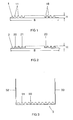
- FIG. 1 shows a first exemplary embodiment of the insertion mat according to the invention shown schematically.
- This insert mat 1 is made of silicone and has a Width B of 80 mm and a thickness H of 5 mm.
- the bottom of the insert mat 1 is flat, while its upper side with a plurality of longitudinal grooves 10th is provided, which have a depth of 4 mm.
- the longitudinal grooves 10 are laterally bounded by fins 11.
- the insert mat 1 is flexible and flexible.
- FIG. 2 shows a second embodiment of the insert mat according to the invention in a schematic representation.
- This insert mat 2 is made of silicone and has a width B of 80 mm and a thickness H of 5 mm.
- the bottom of the Lying mat 2 is flat, while its top with a variety of Longitudinal channels 20 is provided, which have a depth of 4 mm.
- the longitudinal channels 20 are bounded laterally by hollow blades 21.
- the insert mat 2 is flexible and flexible.
- FIG. 3 shows a third exemplary embodiment of the insert mat according to the invention shown schematically.
- This insert mat 3 is also made of silicone.
- the bottom of the insert mat 3 is flat, while its top with a plurality of longitudinal grooves 30 having a depth of 4 mm.
- the longitudinal grooves 30 are bounded laterally by fins 31.
- the thickness of the mat 3 is 5 mm.
- the insert mat 3 respectively a longitudinally extending, integrally formed side wall 32 and 33, respectively.
- the Lying mat 3 is flexible and flexible. This insert mat 3 allows a thermal Coupling to the ground and two side walls of the housing of an electric Device as well as an electrical insulation of the components.
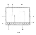
- FIG 4 is a cross section through an operating device for electric lamps shown schematically.
- the operating device has a substantially cuboidal Housing with a bottom 40, two side walls 41, 42, a cover 43rd and two end-side sidewalls (not shown). Inside the case are arranged on a mounting board 44, electronic components 45 arranged to the Operation of one or more electric lamps serve.
- the mounting board 44 is arranged at a distance of about 5 mm above the bottom 40.
- Figure 1 illustrated insert mat 1 In the space between the bottom 40 and the mounting board 44 is located in Figure 1 illustrated insert mat 1.
- the flat bottom of the insert mat 1 lies on the bottom 40, while provided with the longitudinal grooves 10 and fins 11 Top is in contact with the mounting board.
Abstract
Description
Die Erfindung betrifft ein Verfahren zur Herstellung wärmeleitender Einlegematten
für elektrische und elektronische Geräte gemäß des Oberbegriffs des Patentanspruchs
1 und wärmeleitende Einlegematten gemäß des Oberbegriffs des Patentanspruchs 3
sowie Betriebsgeräte für elektrische Lampen mit derartigen Einlegematten.The invention relates to a method for producing thermally conductive insert mats
for electrical and electronic equipment according to the preamble of the
Die Offenlegungsschrift EP 0 986 292 A2 offenbart eine wärmeleitende Einlegematte für elektrische und elektronische Geräte, die aus einem modifizierten Kohlenwasserstoffharz oder aus einer Silikonverbundfolie besteht. Diese Einlegematten sind verformbar, biegsam und weisen eine weiche sowie klebrige Konsistenz auf. Die Einlegematten werden aus einer Vergussmasse hergestellt, die in Formen gegossen wird und anschließend unter Vakuum und Zufuhr von Wärme ungefähr acht Stunden ausgehärtet wird. Die Kosten dieser Einlegematten sind aufgrund des zeitaufwändigen Herstellungsverfahrens und der großen Anzahl der benötigten Gussformen für die Einlegematten unterschiedlicher Abmessungen hoch.The published patent EP 0 986 292 A2 discloses a thermally conductive insert mat for electrical and electronic equipment consisting of a modified hydrocarbon resin or consists of a silicone composite film. These mats are deformable, flexible and have a soft and sticky consistency. The Insert mats are made from a potting compound that is poured into molds and then under vacuum and heat for about eight hours is cured. The cost of these mats are due to the time-consuming Manufacturing process and the large number of required molds for the mats of different dimensions high.
Es ist die Aufgabe der Erfindung, ein vereinfachtes Verfahren zur Herstellung wärmeleitender Einlegematten für elektrische und elektronische Geräte sowie derartige Einlegematten bereitzustellen.It is the object of the invention to provide a simplified process for producing thermally conductive Insert mats for electrical and electronic devices and such To provide mats.
Diese Aufgabe wird erfindungsgemäß durch die Merkmale des Patentanspruchs 1
bzw. 3 gelöst. Besonders vorteilhafte Ausführungen der Erfindung sind in den abhängigen
Patentansprüchen beschrieben. This object is achieved by the features of
Erfindungsgemäß werden die wärmeleitenden Einlegematten für elektrische und elektronische Geräte aus einem elektrisch isolierenden, wärmeleitenden Kunststoff durch Strangpressen mittels eines Extruders hergestellt. Dieses Verfahren erlaubt im Gegensatz zum Herstellungsverfahren gemäß des Standes der Technik eine kostengünstige Massenfertigung der Einlegematten. Die Form der Einlegematten ist durch die Gestalt der Austrittsdüsenöffnung des Extruders bestimmt und kann daher ohne großen Aufwand an die gewünschte Anwendung angepasst werden. Insbesondere werden keine Gussformen mehr benötigt wie beim Herstellungsverfahren gemäß des Standes der Technik. Zur Herstellung der wärmeleitenden Einlegematten können alle thermoplastischen, wärmeleitenden Kunststoffe verwendet werden. Besonders vorteilhaft sind allerdings solche Kunststoffe, die neben einer hohen Wärmeleitfähigkeit auch eine gute elektrische Isolierung ermöglichen. Die Einlegematten gemäß des bevorzugten Ausführungsbeispiel bestehen daher aus Silikon.According to the invention, the heat-conductive insert mats for electrical and electronic Devices made of an electrically insulating, thermally conductive plastic produced by extrusion by means of an extruder. This procedure allows in Contrary to the manufacturing method according to the prior art, a cost-effective Mass production of the mats. The shape of the mats is through determines the shape of the outlet nozzle opening of the extruder and can therefore without great effort to be adapted to the desired application. Especially No casting molds are required as in the manufacturing process according to the State of the art. For the production of thermally conductive mats all thermoplastic, thermally conductive plastics are used. Especially advantageous However, such plastics are in addition to a high thermal conductivity also allow a good electrical insulation. The mats according to the preferred embodiment therefore consist of silicone.
Entsprechend dem erfindungsgemäßen Herstellungsverfahren sind die erfindungsgemäßen wärmeleitenden Einlegematten als Kunststoff-Strangpress-Profil ausgebildet. Die erfindungsgemäßen Einlegematten weisen vorteilhaft eine ebene Unterseite und eine mit Längsrinnen versehene Oberseite auf. Die ebene Unterseite erlaubt eine gute thermische Kopplung zu einer Gehäusewand eines elektrischen Gerätes, während die Lamellen auf der Oberseite, welche die Längsrinnen begrenzen, unterschiedliche Abstände zwischen der Gehäusewand und der Wärmequelle ausgleichen können, da die Lamellen flexibel und biegsam sind. Die Lamellen können hohl ausgebildet sein, um die Flexibilität zu erhöhen.According to the production process according to the invention are the inventive thermally conductive insert mats designed as plastic extruded profile. The insert mats according to the invention advantageously have a flat underside and a longitudinal trough provided on top. The flat bottom allows one good thermal coupling to a housing wall of an electrical device while the louvers on the top, which delimit the longitudinal grooves, are different Clear the gaps between the housing wall and the heat source can, because the lamellae are flexible and flexible. The slats can be hollow to increase flexibility.
Ein bevorzugtes Anwendungsgebiet für die erfindungsgemäßen wärmeleitenden Einlegematten sind Betriebsgräte für elektrische Lampen. Diese Betriebsgerät besitzen üblicherweise ein Gehäuse und innerhalb des Gehäuses angeordnete elektronische Bauteile zum Betrieb von Lampen. Um die von den elektronischen Bauteilen generierte Wärme über das Gehäuse besser abführen zu können, ist zwischen den elektronischen Bauteilen und dem Gehäuse mindestens eine der erfindungsgemäßen Einlegematten angeordnet. Die elektronischen Bauteile des Betriebsgerätes sind vorzugsweise auf einer Montageplatine fixiert, die mit geringem Abstand zu einer Gehäusewand, beispielsweise zum Boden des Betriebsgerätes angeordnet ist. Eine erfindungsgemäße Einlegematte ist vorteilhaft zwischen der Montageplatine und der vorgenannten Gehäusewand des Betriebsgerätes angeordnet, um eine gute thermische Kopplung zwischen den elektronischen Bauteilen und dieser Gehäusewand zu erhalten. Zur weiteren Verbesserung der Wärmeabfuhr kann die mittels der Einlegematte thermisch an die Montagplatine gekoppelte Gehäusewand als Wärmesenke ausgebildet sein, indem sie beispielsweise aus einem Metallblech besteht oder mit einem Metallblech versehen ist.A preferred field of application for the thermally conductive insertable mats according to the invention are factory baton for electric lamps. Own this operating device usually a housing and disposed within the housing electronic Components for the operation of lamps. To those generated by the electronic components Heat to dissipate through the housing better is between the electronic Components and the housing at least one of the insertion mats according to the invention arranged. The electronic components of the operating device are preferably fixed on a mounting board, which is at a short distance to a housing wall, is arranged for example to the bottom of the operating device. An inventive Insert mat is advantageous between the mounting board and the aforementioned Housing wall of the control gear arranged to a good thermal To obtain coupling between the electronic components and this housing wall. To further improve the heat dissipation can by means of the insert mat thermally coupled to the mounting board housing wall formed as a heat sink be, for example, by a sheet of metal or with a metal sheet is provided.
Nachstehend wird die Erfindung anhand bevorzugter Ausführungsbeispiele näher erläutert. Es zeigen:
Figur 1- Eine Seitenansicht eines ersten Ausführungsbeispiels der erfindungsgemäßen Einlegematte
Figur 2- Eine Seitenansicht eines zweiten Ausführungsbeispiels der erfindungsgemäßen Einlegematte
Figur 3- Eine Seitenansicht eines dritten Ausführungsbeispiels der erfindungsgemäßen Einlegematte
- Figur 4
- Einen Querschnitt durch ein Betriebsgerät für elektrische Lampen
- FIG. 1
- A side view of a first embodiment of the invention insert mat
- FIG. 2
- A side view of a second embodiment of the insert mat according to the invention
- FIG. 3
- A side view of a third embodiment of the invention insert mat
- FIG. 4
- A cross section through an operating device for electric lamps
In der Figur 1 ist ein erstes Ausführungsbeispiel der erfindungsgemäßen Einlegematte
schematisch dargestellt. Diese Einlegematte 1 besteht aus Silikon und besitzt eine
Breite B von 80 mm sowie eine Dicke H von 5 mm. Die Unterseite der Einlegematte
1 ist eben ausgebildet, während ihre Oberseite mit einer Vielzahl von Längsrinnen 10
versehen ist, die eine Tiefe von 4 mm aufweisen. Die Längsrinnen 10 werden seitlich
von Lamellen 11 begrenzt. Die Einlegematte 1 ist flexibel und biegsam.FIG. 1 shows a first exemplary embodiment of the insertion mat according to the invention
shown schematically. This
Die Figur 2 zeigt ein zweites Ausführungsbeispiel der erfindungsgemäßen Einlegematte
in schematischer Darstellung. Diese Einlegematte 2 besteht aus Silikon und
besitzt eine Breite B von 80 mm sowie eine Dicke H von 5 mm. Die Unterseite der
Einlegematte 2 ist eben ausgebildet, während ihre Oberseite mit einer Vielzahl von
Längsrinnen 20 versehen ist, die eine Tiefe von 4 mm aufweisen. Die Längsrinnen
20 werden seitlich von hohlen Lamellen 21 begrenzt. Die Einlegematte 2 ist flexibel
und biegsam.FIG. 2 shows a second embodiment of the insert mat according to the invention
in a schematic representation. This
In der Figur 3 ist ein drittes Ausführungsbeispiel der erfindungsgemäßen Einlegematte
schematisch dargestellt. Diese Einlegematte 3 besteht ebenfalls aus Silikon.
Die Unterseite der Einlegematte 3 ist eben ausgebildet, während ihre Oberseite mit
einer Vielzahl von Längsrinnen 30 versehen ist, die eine Tiefe von 4 mm aufweisen.
Die Längsrinnen 30 werden seitlich von Lamellen 31 begrenzt. Die Dicke der Einlegematte
3 beträgt 5 mm. An ihren beiden Seitenkanten weist die Einlegematte 3 jeweils
eine in Längsrichtung verlaufende, angeformte Seitenwand 32 bzw. 33 auf. Die
Einlegematte 3 ist flexibel und biegsam. Diese Einlegematte 3 ermöglicht eine thermische
Kopplung an den Boden und zwei Seitenwänden des Gehäuses eines elektrischen
Gerätes sowie auch eine elektrische Isolierung der Bauelemente.FIG. 3 shows a third exemplary embodiment of the insert mat according to the invention
shown schematically. This
Zur Herstellung der oben beschriebenen Einlegematten wird Silikon, beispielsweise in Form von Pulver oder Granulat, in einen Extruder gefüllt und unter Wärmezufuhr mittels einer Schnecke homogenisiert und dabei zur formgebenden Düse im Spritzkopf des Extruders transportiert. Das Extrudieren bzw. Strangpressen an sich ist ein bekanntes Verfahren und soll daher hier nicht näher erläutert werden. Die Gestalt der Düsenöffnung im Spritzkopf entspricht jeweils den in den Figuren 1 bis 3 abgebildeten Profilen der Einlegematten.For the preparation of the above-described insertion mats silicone, for example in the form of powder or granules, filled in an extruder and under heat homogenized by means of a screw and thereby to the shaping nozzle in the spray head transported by the extruder. The extrusion or extrusion itself is a Known method and will therefore not be explained in detail here. The figure of Nozzle opening in the spray head corresponds in each case to that shown in FIGS. 1 to 3 Profiles of the mats.
In der Figur 4 ist ein Querschnitt durch ein Betriebsgerät für elektrische Lampen
schematisch dargestellt. Das Betriebsgerät besitzt ein im wesentlichen quaderförmiges
Gehäuse mit einem Boden 40, zwei Seitenwänden 41, 42, einer Abdeckung 43
und zwei stirnseitigen Seitenwänden (nicht abgebildet). Innerhalb des Gehäuses sind
auf einer Montageplatine 44 fixierte, elektronische Bauteile 45 angeordnet, die zum
Betrieb einer oder mehrerer elektrischer Lampen dienen. Die Montageplatine 44 ist
in einem Abstand von ungefähr 5 mm oberhalb des Bodens 40 angeordnet. Im Zwischenraum
zwischen dem Boden 40 und der Montageplatine 44 befindet sich die in
Figur 1 abgebildet Einlegematte 1. Die ebene Unterseite der Einlegematte 1 liegt auf
dem Boden 40 auf, während die mit den Längsrinnen 10 bzw. Lamellen 11 versehene
Oberseite sich im Kontakt mit der Montageplatine befindet.In the figure 4 is a cross section through an operating device for electric lamps
shown schematically. The operating device has a substantially cuboidal
Housing with a bottom 40, two
Claims (7)
Applications Claiming Priority (2)
| Application Number | Priority Date | Filing Date | Title |
|---|---|---|---|
| DE2003159157 DE10359157A1 (en) | 2003-12-16 | 2003-12-16 | Heat-conductive insert mat for electrical and electronic devices and method for producing such insert mats |
| DE10359157 | 2003-12-16 |
Publications (2)
| Publication Number | Publication Date |
|---|---|
| EP1545180A2 true EP1545180A2 (en) | 2005-06-22 |
| EP1545180A3 EP1545180A3 (en) | 2008-03-05 |
Family
ID=34485428
Family Applications (1)
| Application Number | Title | Priority Date | Filing Date |
|---|---|---|---|
| EP04027142A Withdrawn EP1545180A3 (en) | 2003-12-16 | 2004-11-15 | Thermal transfer mat for electrical or electronic apparatuses and process for producing it |
Country Status (2)
| Country | Link |
|---|---|
| EP (1) | EP1545180A3 (en) |
| DE (1) | DE10359157A1 (en) |
Cited By (2)
| Publication number | Priority date | Publication date | Assignee | Title |
|---|---|---|---|---|
| EP2442630A1 (en) * | 2010-10-18 | 2012-04-18 | Siemens Aktiengesellschaft | Heat conducting pad |
| WO2012080827A3 (en) * | 2010-12-17 | 2012-08-30 | Eaton Corporation | Electrical system and matrix assembly therefor |
Families Citing this family (4)
| Publication number | Priority date | Publication date | Assignee | Title |
|---|---|---|---|---|
| DE202006007475U1 (en) * | 2006-05-09 | 2007-09-13 | ICOS Gesellschaft für Industrielle Communications-Systeme mbH | Switching arrangement for communication data streams, switch module for such a switch arrangement and cooling arrangement therefor |
| DE202008012361U1 (en) | 2008-09-15 | 2012-12-14 | Gerhard Menninga | A plate and arrangement for equalizing heat in a printed circuit board and dissipating heat from the printed circuit board and elements located on the printed circuit board |
| DE102008047649B4 (en) | 2008-09-15 | 2011-03-31 | Gerhard Menninga | A plate for balancing heat in a printed circuit board and for dissipating heat from a printed circuit board and arranging such a board with a printed circuit board |
| DE102016220877A1 (en) * | 2016-10-24 | 2018-04-26 | Volkswagen Aktiengesellschaft | Wärmeleitmatte, battery assembly with such a heat-conducting mat and vehicle |
Citations (5)
| Publication number | Priority date | Publication date | Assignee | Title |
|---|---|---|---|---|
| US4654754A (en) * | 1982-11-02 | 1987-03-31 | Fairchild Weston Systems, Inc. | Thermal link |
| US6037397A (en) * | 1997-11-27 | 2000-03-14 | Denki Kagaku Kogyo Kabushiki Kaisha | Rubber molded product |
| EP0986292A2 (en) * | 1998-09-09 | 2000-03-15 | Patent-Treuhand-Gesellschaft für elektrische Glühlampen mbH | Thermal transfer mat for electrical or electronic apparatuses |
| EP1265281A2 (en) * | 2001-06-06 | 2002-12-11 | Polymatech Co., Ltd. | Thermally conductive molded article and method of making the same |
| EP1286394A2 (en) * | 2001-08-17 | 2003-02-26 | Polymatech Co., Ltd. | Thermally conductive sheet |
-
2003
- 2003-12-16 DE DE2003159157 patent/DE10359157A1/en not_active Withdrawn
-
2004
- 2004-11-15 EP EP04027142A patent/EP1545180A3/en not_active Withdrawn
Patent Citations (5)
| Publication number | Priority date | Publication date | Assignee | Title |
|---|---|---|---|---|
| US4654754A (en) * | 1982-11-02 | 1987-03-31 | Fairchild Weston Systems, Inc. | Thermal link |
| US6037397A (en) * | 1997-11-27 | 2000-03-14 | Denki Kagaku Kogyo Kabushiki Kaisha | Rubber molded product |
| EP0986292A2 (en) * | 1998-09-09 | 2000-03-15 | Patent-Treuhand-Gesellschaft für elektrische Glühlampen mbH | Thermal transfer mat for electrical or electronic apparatuses |
| EP1265281A2 (en) * | 2001-06-06 | 2002-12-11 | Polymatech Co., Ltd. | Thermally conductive molded article and method of making the same |
| EP1286394A2 (en) * | 2001-08-17 | 2003-02-26 | Polymatech Co., Ltd. | Thermally conductive sheet |
Cited By (5)
| Publication number | Priority date | Publication date | Assignee | Title |
|---|---|---|---|---|
| EP2442630A1 (en) * | 2010-10-18 | 2012-04-18 | Siemens Aktiengesellschaft | Heat conducting pad |
| WO2012080827A3 (en) * | 2010-12-17 | 2012-08-30 | Eaton Corporation | Electrical system and matrix assembly therefor |
| US8514552B2 (en) | 2010-12-17 | 2013-08-20 | Eaton Corporation | Electrical system and matrix assembly therefor |
| CN103329640A (en) * | 2010-12-17 | 2013-09-25 | 伊顿公司 | Electrical system and matrix assembly therefor |
| CN103329640B (en) * | 2010-12-17 | 2016-02-10 | 雷比诺有限责任公司 | Electrical system and matrix assemblies thereof |
Also Published As
| Publication number | Publication date |
|---|---|
| EP1545180A3 (en) | 2008-03-05 |
| DE10359157A1 (en) | 2005-07-21 |
Similar Documents
| Publication | Publication Date | Title |
|---|---|---|
| EP0654819B2 (en) | Fabrication process for a heat dissipation device | |
| DE102010016534A1 (en) | Lighting device with several, arranged in a heat sink lighting units | |
| DE102007012818A1 (en) | Semiconductor device for use in inverter controller, has fastener with multiple fixing positions, formed along edge, forms opening and connection, which is fastened to edge and is electrically connected with semiconductor assembly substrate | |
| DE102016124172A1 (en) | Connector for powerless contacting on a printed circuit board | |
| DE2726742A1 (en) | INTERMEDIATE CONNECTOR | |
| DE102016103439B4 (en) | Contact point of a flat conductor | |
| EP1884383A1 (en) | Electric heating device, in particular for a vehicle | |
| DE102005043055B3 (en) | Electronics housing cooling body with cooling fins, useful in automobiles, is produced inexpensively from extruded profiled slabs, specifically of aluminum, by cutting to length using profiled circular saw | |
| EP3668295A1 (en) | Control device for evaluating signals for a vehicle and method for producing a control device for evaluating signals for a vehicle | |
| EP1545180A2 (en) | Thermal transfer mat for electrical or electronic apparatuses and process for producing it | |
| EP0616401B1 (en) | Busbar package | |
| DE19963332A1 (en) | Conducting wire carrier for use in motor vehicle has rows of snap protrusions on surface of insulating coating at same interval as through holes and each able to be brought into engagement with a through hole | |
| DE112016002376T5 (en) | ELECTRICAL DEVICE AND METHOD FOR PRODUCING AN ELECTRICAL DEVICE | |
| DE19629688A1 (en) | Flexible ribbon cable especially suitable for motor vehicle wiring loom | |
| DE19958163C1 (en) | Profile rod system for frame construction for shelving or fencing has combined optical or electrical conductor extending along length of at least one extruded aluminum profile rod | |
| EP0271163B1 (en) | Manufacturing method of electrical circuit boards | |
| DE102018103669B3 (en) | Tapping device for transmitting electrical energy and tapping system | |
| DE4212065A1 (en) | Cable distributor cabinet with rotatively insulated current rails - has rails embedded in plastics material of distributor housing wall with projecting fixing points for fuse rail connections | |
| EP1212813A1 (en) | Cable connection between flat ribbon cable and round ribbon cable or round cable and method for producing the same | |
| DE2153580C3 (en) | Terminal strip with connecting bar for electrical circuit parts and method for producing the connecting bar | |
| EP3503671B1 (en) | Electric heating device and a method for manufacturing the same | |
| DE3211540A1 (en) | MINIATURE HIGH CAPACITY RAIL AND METHOD FOR PRODUCING THE SAME | |
| WO2017001108A1 (en) | Circuit support for an electronic circuit, and method for manufacturing a circuit support of said type | |
| DE3740025C2 (en) | ||
| EP2027948A1 (en) | Method for producing a flat section, in particular a cooling body for semiconductor elements or similar components, and section for same |
Legal Events
| Date | Code | Title | Description |
|---|---|---|---|
| PUAI | Public reference made under article 153(3) epc to a published international application that has entered the european phase |
Free format text: ORIGINAL CODE: 0009012 |
|
| AK | Designated contracting states |
Kind code of ref document: A2 Designated state(s): AT BE BG CH CY CZ DE DK EE ES FI FR GB GR HU IE IS IT LI LU MC NL PL PT RO SE SI SK TR |
|
| AX | Request for extension of the european patent |
Extension state: AL HR LT LV MK YU |
|
| PUAL | Search report despatched |
Free format text: ORIGINAL CODE: 0009013 |
|
| AK | Designated contracting states |
Kind code of ref document: A3 Designated state(s): AT BE BG CH CY CZ DE DK EE ES FI FR GB GR HU IE IS IT LI LU MC NL PL PT RO SE SI SK TR |
|
| AX | Request for extension of the european patent |
Extension state: AL HR LT LV MK YU |
|
| AKX | Designation fees paid | ||
| STAA | Information on the status of an ep patent application or granted ep patent |
Free format text: STATUS: THE APPLICATION IS DEEMED TO BE WITHDRAWN |
|
| 18D | Application deemed to be withdrawn |
Effective date: 20080906 |
|
| REG | Reference to a national code |
Ref country code: DE Ref legal event code: 8566 |