BACKGROUND OF THE INVENTION
The present invention relates to an apparatus, a method,
and a program for processing information
regarding content data.
Conventionally, in the case of imaging a subject with an
imaging apparatus such as a video camera, in order to provide
a variety of video effects, there is a method for e. g. varying
the number of obtained frames per second by varying the number
of times of outputting data per second at an imager such as a
CCD.
With this method, it is possible to perform high-speed
imaging which brings about low-speed playback (slow-motion
playback) at the time of normal playback by capturing an image
at higher speed than in the case of normal imaging (increasing
the number of times of capturing, that is, increasing the number
of times of photoelectric conversion processing per second at
the imager) , and low-speed imaging which brings about high-speed
playback (fast-forward playback) at the time of the normal
playback by decreasing the number of times of capturing the image
(i.e., decreasing the number of times of the photoelectric
conversion processing per second at the imager) , as well as the
normal imaging for capturing the image at the same rate as a
playback rate (the number of played-back frames per second) of
the normal playback (i.e., controlling the number of times of
the photoelectric conversion processing per second at the imager
to obtain a frame of image data at the same rate as the playback
rate) .
To be specific, for example, there has been a method for
varying an imaging frame rate which is the number of frames of
an image obtained with photoelectric conversion at a CCD per
second, by controlling a retrace time added to an imaging signal
obtained by imaging a subj ect, with an image signal of the imaging
frame rate being an image signal of a CDR system (Common Data
Rate: a common sampling frequency system). Further, there has
been a method for obtaining an image signal of an output frame
rate by generating an image signal of an imaging frame rate and
performing frame addition using the image signal of the imaging
frame rate. Furthermore, there has been a method for generating
an image signal of an output frame rate based on a frame rate
setting signal from an image signal of an imaging frame rate
by switching the number of additional frames at frame addition
in the case where the image signal of the output frame rate based
on the frame rate setting signal cannot be obtained even though
the imaging frame rate is varied within a specified period (see
patent document 1, for example).
Further, there are cases where, for example, an image
captured by a CCD with a progressive system is converted into
interlaced-system data, or a film image is converted into
interlaced-system data, that is, a system of the obtained image
data is converted.
Patent document 1: WO 03/063472 A1
In the case of playing back the image data obtained with
the image capture rate varied and the converted image data at
the time of imaging as described above, effects of outputted
images on which the same normal playback is performed differ
depending on processing performed on the data at the time of
imaging, and there is a problem that it is difficult for a user
who plays back the data to grasp correctly what kind of processing
has been performed on the data.
In particular, in the case where persons, places, or dates
differ between in imaging work and playback and edit work due
to large-scale production work such as production of a Tvprogram,
it is difficult for an editor who conducts the edit work to grasp
correctly what kind of setting a photographer who conducts the
imaging work has chosen to image a subject and obtain image data
to be edited.
Further, it is desirable to output image data with the
interlaced system if the image data has been captured with the
interlaced system at the time of imaging for example, but it
is possible to output image data converted into data with the
progressive system again if the image data has been captured
with the progressive system and converted into data with the
interlaced system. However, in the case of playing back and
outputting image data that has been converted from the
progressive system to the interlaced system, there is a problem
that a player which is a playback output apparatus cannot play
back image data except with the interlaced system because the
image data consists with the interlaced system.
SUMMARY OF THE INVENTION
In view of the above problems, embodiments of the
present invention can provide a user with an apparatus that
plays back data with information regarding settings at the
time of imaging and recording so that they can perform more
effective playback processing or output processing.
Embodiments of the present invention relate to an
apparatus, a method, and a program for processing information
so designed as to be effective in playback processing or
output processing.
A first aspect of the present invention resides in an
information processing apparatus which comprises a creation
device for creating a capture rate which is information regarding
a data rate at the time of inputting or generating content data,
a REC rate which is information regarding a data rate at the
time of recording the content data, and a format rate which is
a data rate at the time of normal playback of the content data.
In the first aspect, the content data can be image data.
In the first aspect, the information processing apparatus
can further comprise an imaging device for imaging a subject
and generating image data as the content data and the creation
device can create, as the capture rate, information regarding
a data rate of the content data at the time when the imaging
device generates the content data.
In the first aspect, the information processing apparatus
can further comprise a content data record device for recording
the content data onto a record medium and the creation device
can create, as the REC rate, information regarding a data rate
of the content data at the time when the content data record
device records the content data onto the record medium.
In the first aspect, the information processing apparatus
can further comprise an input reception device for receiving
a control instruction regarding input, generation, record, or
playback of the content data that a user inputs and the creation
device can create the capture rate, the REC rate, and the format
rate based on the control instruction received by the input
reception device.
In the first aspect, the information processing apparatus
can further comprise a rate information record device for
recording the capture rate, the REC rate, and the format rate
which are created by the creation device onto a record medium.
In the first aspect, the rate information record device
can record a transition point of the capture rate, the REC rate,
and the format rate onto the record medium.
In the first aspect, the rate information record device
can relate information regarding a UMID of the content data to
the capture rate, the REC rate, and the format rate and can further
record the information regarding the UMID of the content data
onto the record medium.
In the first aspect, the information processing apparatus
can further comprise a rate information transmission device for
transmitting the capture rate, the REC rate, and the format rate
which are created by the creation device to a different
information processing apparatus.
In the first aspect, the rate information transmission
device can transmit a transition point of the capture rate, the
REC rate, and the format rate to the different information
processing apparatus.
In the first aspect, the rate information transmission
device can relate information regarding a UMID of the content
data to the capture rate, the REC rate, and the format rate and
can further transmit the information regarding the UMID of the
content data to the different information processing apparatus.
A second aspect of the present invention resides in a
information processing method which comprises a creation step
of creating a capture rate which is information regarding a data
rate at the time of inputting or generating the content data,
a REC rate which is information regarding a data rate at the
time of recording the content data, and a format rate which is
a data rate at the time of normal playback of the content data.
A third aspect of the present invention resides in a program
which makes a computer perform a creation step of creating a
capture rate which is information regarding a data rate at the
time of inputting or generating the content data, a REC rate
which is information regarding a data rate at the time of recording
the content data, and a format rate which is a data rate at the
time of normal playback of the content data.
A fourth aspect of the present invention resides in a
information processing apparatus which comprises a
determinationdevice fordetermininga setting regarding at least
one of playback processing and output processing of the content
data based on a capture rate which is information regarding a
data rate at the time of inputting or generating the content
data, a REC rate which is information regarding a data rate at
the time of recording the content data, and a format rate which
is a data rate at the time of normal playback of the content
data.
In the fourth aspect, the content data can be image data.
In the fourth aspect, the information processing apparatus
can further comprise a playback device for playing back the
content data at a data rate based on the format rate.
In the fourth aspect, the information processing apparatus
can further comprise an output device for outputting the content
data played back by the playback device.
In the fourth aspect, the information processing apparatus
can further comprise a data conversion device for converting
the content data played back by the playback device based on
a determination result by the determination device and the output
device can output the content data converted by the data
conversion device.
In the fourth aspect, the information processing apparatus
can further comprise an output information creation device for
creating output information for outputting a determination
result by the determination device or the capture rate, the REC
rate, and the format rate and the output device can further output
the output inf ormat ion created by the output information creation
device.
In the fourth aspect, the information processing apparatus
can further comprise an acquisition device for reading and
acquiring the capture rate, the REC rate, and the format rate
recorded on a record medium and the determination device can
determine a setting regarding playback processing and output
processing of the content data based on the capture rate, the
REC rate, and the format rate which are read and acquired from
the record medium by the acquisition device.
In the fourth aspect, the information processing apparatus
can further comprise a receiving device for receiving the capture
rate, the REC rate, and the format rate which are transmitted
from a different information processing apparatus and the
determination device can determine a setting regarding playback
processing and output processing of the content data based on
the capture rate, the REC rate, and the format rate which are
received by the receiving device.
A fifth aspect of the present invention resides in a
information processing method which comprises a determination
step of determining a setting regarding at least one of playback
processing and output processing of the content data based on
a capture rate which is information regarding a data rate at
the time of inputting or generating the content data, a REC rate
which is information regarding a data rate at the time of recording
the content data, and a format rate which is a data rate at the
time of normal playback of the content data.
A sixth aspect of the present invention resides in a program
which makes a computer perform a determination step of
determining a setting regarding at least one of playback
processing and output processing of the content data based on
a capture rate which is information regarding a data rate at
the time of inputting or generating the content data, a REC rate
which is information regarding a data rate at the time of recording
the content data, and a format rate which is a data rate at the
time of normal playback of the content data.
According to the first to third aspects, the apparatus,
the method, and the program create a capture rate which is
information regarding a data rate at the time of inputting or
generating content data, a REC rate which is information
regarding a data rate at the time of recording the content data,
and a format rate which is a data rate at the time of normal
playback of the content data.
According to the fourth to sixth aspects, the apparatus,
the method, and the program determine a setting regarding at
least one of playback processing and output processing of the
content data based on a capture rate which is information
regarding a data rate at the time of inputting or generating
the content data, a REC rate which is information regarding a
data rate at the time of recording the content data, and a format
rate which is a data rate at the time of normal playback of the
content data.
The aspects of the present invention aims to process
information, in particular, to allow settings at the time of
imaging and recording to be obtained at the time of playing back
and outputting data so that more effective playback processing
and output processing can be performed.
Other and further objects, features and advantages of the
invention will appear more fully from the following description.
BRIEF DESCRIPTION OF THE DRAWINGS
The invention will now be described by way of example
with reference to the accompanying drawings, throughout which
like parts are referred to by like references, and in which:
DETAILED DESCRIPTION OF THE PREFERRED EMBODIMENTS
Hereinafter, embodiments of the present invention will
be described. Before describing these, a description will be
made below to exemplify corresponding relationships between
constituent features described in the claims and specific
examples in the embodiments. This description is to verify that
the specific examples which support the invention described in
the claims are described in the embodiments of the invention.
Therefore, even if there is a specific example that is described
in the embodiments of the invention but not described in this
description as a specific example corresponding to a constituent
feature, it does not mean that the specific example does not
correspond to the constituent feature. On the other hand, even
if there is a specific example that is described in this
description as a specific example corresponding to a constituent
feature, it does not mean that the specific example does not
correspond to other constituent features than the constituent
feature.
Further, this description does not mean that the invention
corresponding to the specific examples described in the
embodiments is all described in the claims. In other words,
this description does not deny existence of an invention that
corresponds to the specif ic examples described inthe embodiments
and is not described in the claims in this application, that
is, existence of an invention that is added by a divisional
application or an amendment in the future.
According to the present invention, there is provided an
information processing apparatus (e.g., an imaging record
apparatus 11 in FIG. 1) for processing information regarding
content data (e.g., image data 31 and audio data 32 in FIG. 1) .
The information processing apparatus comprises a creation device
(e. g., a rate information creation unit 24 in FIG. 1) for creating
a capture rate (e.g., a capture rate 41 in FIG. 1) which is
information regarding a data rate at the time of inputting or
generating the content data, a REC rate (e.g., a REC rate 42
in FIG. 1) which is information regarding a data rate at the
time of recording the content data, and a format rate (e.g.,
a format rate 43 in FIG. 1) which is a data rate at the time
of normal playback of the content data.
The content data can be image data (e.g., image data 31
in FIG. 1).
The information processing apparatus can further comprise
an imaging device (e.g. , an imaging unit 22 in FIG. 1) for imaging
a subject and generating image data as the content data and the
creation device can create, as the capture rate, information
regarding a data rate of the content data at the time when the
imaging device generates the content data (e.g., step S33 in
FIG. 13).
The information processing apparatus can further comprise
a content data record device (e.g., a record unit 23 in FIG.
1) for recording the content data onto a record medium and the
creation device can create, as the REC rate, information
regarding a data rate of the content data at the time when the
content data record device records the content data onto the
record medium (e.g., step S32 in FIG. 13).
The information processing apparatus can further comprise
an input reception device (e.g., an input unit 104 in FIG. 2)
for receiving a control instruction (an input imaging record
mode instruction in FIG. 1) regarding input, generation, record,
or playback of the content data that a user inputs and the creation
device can create the capture rate, the REC rate, and the format
rate based on the control instruction received by the input
reception device (e.g., steps S31 to S33 in FIG. 13).
The information processing apparatus can further comprise
a rate information record device (e.g., a record unit 23 in FIG.
1) for recording the capture rate, the REC rate, and the format
rate which are createdby the creation device onto a recordmedium.
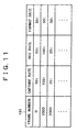
The rate information record device can record a transition
point of the capture rate, the REC rate, and the format rate
(e.g., a table 191 in FIG. 11) onto the record medium.
The rate information record device can relate information
(e.g., UMID information 242 in FIG. 12) regarding a UMID (e.g.,
a UMID 231 in FIG. 12) of the content data to the capture rate,
the REC rate, and the format rate which are created by the creation
device and can further record the information regarding the UMID
of the content data onto the record medium.
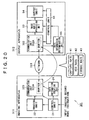
The information processing apparatus can further comprise
a rate information transmission device (e.g., a communication
unit 323 in FIG. 20) for transmitting the capture rate, the REC
rate, and the format rate which are created by the creation device
to a different information processing apparatus.
The rate information transmission device can transmit a
transition point of the capture rate, the REC rate, and the format
rate (e.g. , a table 191 in FIG. 11) to the different information
processing apparatus.
The rate information transmission device can relate
information (e.g., UMID information 242 in FIG. 12) regarding
a UMID (e.g., a UMID 231 in FIG. 12) of the content data to the
capture rate, the REC rate, and the format rate and can further
transmit the information regarding the UMID of the content data
to the different information processing apparatus.
According to the present invention, there is provided an
information processing method of an information processing
apparatus (e.g., an imaging record apparatus 11 in FIG. 1) for
processing information regarding content data (e.g., image data
31 and audio data 32 in FIG. 1). The information processing
method comprises a creation step (e.g., steps S31 to S33 in FIG.
13) of creating a capture rate (e.g. , a capture rate 41 in FIG.
1) which is information regarding a data rate at the time of
inputting or generating the content data, a REC rate (e.g., a
REC rate 42 in FIG. 1) which is information regarding a data
rate at the time of recording the content data, and a format
rate (e.g., a format rate 43 in FIG. 1) which is a data rate
at the time of normal playback of the content data.
According to the present invention, there is provided an
information processing apparatus (e.g., a playback output
apparatus 12 in FIG. 1) for processing information regarding
content data (e.g., image data 31 and audio data 32 in FIG. 1) .
The information processing apparatus comprises a determination
device (e.g., a rate information determination unit in FIG. 1) for
determining a setting regarding at least one of playback
processing and output processing of the content data based on
a capture rate which is information regarding a data rate at
the time of inputting or generating the content data, a REC rate
which is information regarding a data rate at the time of recording
the content data, and a format rate which is a data rate at the
time of normal playback of the content data.
The content data can be image data (e.g., image data 31
in FIG. 1).
The information processing apparatus can further comprise
a playback device (e.g., a playback processing unit 142 in FIG.
3) for playing back the content data at a data rate based on
the format rate.
The information processing apparatus can further comprise
an output device (e.g., an output unit 54 in FIG. 1) for outputting
the content data played back by the playback device.
The information processing apparatus can further comprise
a data conversion device (e.g., a data conversion unit 152 in
FIG. 3) for converting the content data played backby the playback
device based on a determination result by the determination
device and the output device can output the content data converted
by the data conversion device.
The information processing apparatus can further comprise
an output information creation device (e.g., an output
information creation unit 153 in FIG. 3) for creating output
information for outputting a determination result by the
determination device and the output device can further output
the output information created by the output information creation
device.
The information processing apparatus can further comprise
an acquisition device (e.g., a pickup unit 141 in FIG. 3) for
reading and acquiring the capture rate, the REC rate, and the
format rate recorded on a record medium and the determination
device can determine a setting regarding playback processing
and output processing of the content data based on the capture
rate, the REC rate, and the format rate which are read and acquired
from the record medium by the acquisition device.
The information processing apparatus can further comprise
a receiving device (e.g., a communication unit 352 in FIG. 20)
for receiving the capture rate, the REC rate, and the format
rate which are transmitted from a different information
processing apparatus and the determination device can determine
a setting regarding playback processing and output processing
of the content data based on the capture rate, the REC rate,
and the format rate which are received by the receiving device.
According to the present invention, there is provided an
information processing method of an information processing
apparatus (e.g., a playback output apparatus 12 in FIG. 1) for
processing information regarding content data (e.g., image data
31 and audio data 32 in FIG. 1). The information processing
method comprises a determination step (e.g., steps S101 to S103
in FIG. 16) of determining a setting regarding at least one of
playback processing and output processing of the content data
based on a capture rate which is information regarding a data
rate at the time of inputting or generating the content data,
a REC rate which is information regarding a data rate at the
time of recording the content data, and a format rate which is
a data rate at the time of normal playback of the content data.
Referring now to the drawings, embodiments of the present
invention will hereinafter be described.
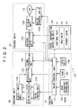
FIG. 1 shows a configuration example of a record playback
system according to the present invention. The record playback
system 1 comprises an imaging record apparatus 11 and a playback
output apparatus 12.
The imaging record apparatus 11 images a subject and
generates image data and audio data, and records it onto an optical
disc 13 as content data. The imaging record apparatus 11 also
creates rate information which is regarding data rates of the
content data, and relates it with the content data to record
it onto the optical disc 13. The playback output apparatus 12
reads out the rate information recorded on the optical disc 13,
and plays back and outputs the content data based on the rate
information.
Further, for example, in the case of image data, a rate
(data rate) refers to the number of frames (fields) per second
which constitutes the image data. Besides the number of frames
or fields, it also refers to whether the image data consists
of frame images or field images (i. e. , an image of an interlaced
system or a progressive system).
Hereunder is a description of the rate (data rate) of the
content data (image data) in various cases such as input, imaging
(generation), recording, receiving, playback, output, etc. In
any case, the rate (data rate) indicates the rate of the content
data itself, but does not indicate processing speed or the like.
For example, in the case of image data, the data rate at the
time of imaging (a capture rate) refers to the number of times
of photoelectric conversion processing per second at an imager,
but does not refer to speeder time of the photoelectric conversion
processing. Further, this also applies to the data rate at the
time of recording for example, and the data rate does not refer
to the processing speed, the processing time, or the recording
density.
The imaging record apparatus 11 is a video camera which
images subjects and records image data of the obtained moving
image and still image, audio data, etc. onto a record medium
as content data in news gathering or the like. The imaging record
apparatus 11 comprises a control unit 21 which controls each
unit, an imaging unit 22 which images a subject, a record unit
23 which records the content data (image data and audio data)
obtained at the imaging unit onto an optical disc 13, and a rate
information creation unit 24 which creates rate information of
the content data. A user of the imaging record apparatus 11
inputs a control instruction such as an imaging start instruction
and an imaging end instruction to the control unit 21.
Furthermore, the user inputs also an input imaging record mode
instruction which is a setting instruction of a mode with regard
to imaging processing and record processing, such as high-speed
imaging, low-speed imaging, etc. The control unit 21 determines
the mode with regard to imaging processing and record processing
based on the input imaging record mode instruction or the like
to control the imaging unit 22 and the record unit 23. Further,
the control unit 21 provides the rate information creation unit
24 with information regarding an input imaging record mode. The
imaging unit 22 images the subject based on the control of the
control unit 21 and acquires audio information and acquires the
content data comprising the image data and the audio data to
provide it to the record unit 23. The rate information creation
unit 24 creates rate information which is regarding rates of
the content data at imaging processing, record processing, and
the like based on the information provided from the control unit
21, and provides it to the record unit 23. The record unit 23
records the content data provided from the imaging unit 22 and
the rate information provided from the rate information creation
unit 24 onto the optical disc 13 as being controlled by the control
unit 21.
The optical disc 13 is a record medium such as a recordable
DVD (Digital Versatile Disc) like Blue-ray Disc (trademark),
a CD (Compact Disc), etc. Image data 31, audio data 32, and
metadata 33 which is related to the content data are recorded
on the optical disc 13. The metadata 33 contains a capture rate
41 which is rate information at the time of capturing an image
(photoelectric conversion) , that is, generating the content data,
a REC rate 42 which is rate information at the time of recording
the content data, and a format rate 43 which is rate information
at the time of playing back the content data, and the like. The
capture rate, the REC rate, and the format rate will be described
in detail later.
The playback output apparatus 12 is an apparatus which
plays back and outputs the image data and the audio data recorded
on the optical disc 13 at edit processing or the like. The
playback output apparatus 12 comprises a control unit 51 which
controls each unit, a playback unit 52 which reads out and plays
back the information recorded on the optical disc 13, an image
audio processing unit 53 which performs predetermined processing
on the content data (the image data and the audio data) played
back by the playback unit 52, an output unit 54 which outputs
the content data processed in the image audio processing unit
53 through a monitor, a speaker, etc., and a rate information
determination unit 55 which determines modes of playback
processing and output processing based on the rate information
provided from the playback unit 52 and provides the resulting
information to the control unit 51. The playback unit 52 reads
out the rate information (the capture rate, the REC rate, and
the format rate) recorded on the optical disc 13 and provides
the rate information to the rate information determination unit
55, as being controlled by the control unit 51. The rate
information determination unit 55 determines processing modes
of the playback unit 52, the image audio processing unit 53,
and the output unit 54 based on the rate information, and provides
the resulting information to the control unit 51. The control
unit 51 controls the playback unit 52, the image audio processing
unit 53, and the output unit 54 based on this information. The
playback unit 52 reads out andplays back the content data recorded
onthe optical disc 13 andprovides it to the image audioprocessing
unit 53, as being controlled by the control unit 51. The image
audio processing unit 53 performs predetermined signal
processing on the content data and provides the resulting data
to the output unit 54. The output unit 54 outputs the content
data provided from the image audio processing unit 53 through
the monitor, the speaker, and the like.
FIG. 2 shows a block diagram of the imaging record apparatus
11 in FIG. 1.
In FIG. 2, a main control unit 101 in the control unit
21 in the imaging record apparatus 11 performs each processing
in accordance with a program stored in a ROM (Read Only Memory)
102 or a program loaded into a RAM (Random Access Memory) 103.
Apparatus information 102A regarding the imaging record
apparatus 11 is stored in the ROM 102. The apparatus information
102A includes information regarding abroadcasting standard that
the imaging record apparatus 11 performs record processing based
on, and is read out by the main control unit 101 as necessary
and provided to the rate information creation unit 24. Further,
data that the main control unit 101 requires to perform each
processing is stored in the RAM 103 as necessary. Furthermore,
an input unit 104 comprises a variety of buttons, switches, etc.,
and receives input from a user to provide the received user input
to the main control unit 101. The main control unit 101 controls
each unit based on the user input.
The lens unit 111 comprises a plurality of lenses etc.
and adjusts an aperture for incident light and a focus. The
incident light into the lens unit 111 is provided to a CCD (Charge
Coupled Device) 112. The CCD 112 converts the incident light
provided through the lens unit 111 into an electric signal and
provides it to a preprocessing unit 113 . Further, an audio input
unit 115 comprises a microphone etc. and collects sound of the
subject and its surroundings and converts it into an electric
signal and then provides it to the preprocessing unit 113 . The
preprocessing unit 113 comprises a CDS circuit, a GCA circuit,
an A/D conversion circuit, etc. and eliminates reset noise
included in an output signal provided from the CCD 112 and
optimizes the gain. The preprocessing unit 113 also converts
the output signal of the CCD 112 into a digital signal to provide
it to a signal processing unit 114 as image data (moving image
data or still image data). Furthermore, the preprocessing unit
113 performs analog-to-digital conversion on an audio signal
provided from the audio input unit 115 to provide it to the signal
processing unit 114 as audio data. The signal processing unit
114 performs image processing such as adjusting exposure and
white balance on the image data provided from the preprocessing
unit 113, and performs audio processing such as eliminating a
noise on the audio data. Moreover, the signal processing unit
114 compresses the image data and the audio data with a
predetermined form to provide it to a record unit 23 as compressed
data for recording. Furthermore, a drive control unit 116 is
controlled by the main control unit 101 in the control unit 21
and controls driving of the lens unit 111 to adjust the aperture
and the focus, and controls electrical operation of the CCD 112,
and adjusts capture timing (timing of the photoelectric
conversion processing) of the image (stored electric charge),
and controls electrical operation of the audio input unit 115,
and adjusts audio input timing, etc.
Furthermore, the rate information creation unit 24
calculates the capture rate 41, the REC rate 42, and the format
rate 43 based on the input imaging record mode instruction from
the user and the apparatus information 102A which are provided
from the main control unit 101 in the control unit 21, and provides
them to a record processing unit 121 in the record unit 23 as
the rate information.
The recordprocessing unit 121 in the record unit 23 performs
encoding, which is required at the time of recording, on the
image data and the audio data provided from the signal processing
unit 114, the rate information provided from the rate information
creation unit 24, etc. and provides them to a pickup unit 122
as recording data. The pickup unit 122 applies laser light for
writing data to the optical disc 13 mounted on a drive (not shown)
to record the recording data provided from the record processing
unit 121 onto the optical disc 13. Furthermore, a drive control
unit 124 is controlled by the main control unit 101 in the control
unit 21 and controls rotation of a spindle motor in the drive
(not shown) and driving of the pickup unit 122 and controls
operation of recording data onto the optical disc 13.
FIG. 3 shows a block diagram of the playback output apparatus
12 in FIG. 1.
In FIG. 3, a main control unit 131 in the control unit
51 in the playback output apparatus 12 performs each processing
in accordance with a program stored in a ROM 132 or a program
loaded into a RAM 133. Further, data that the main control unit
131 requires to perform each processing is stored in the RAM
133 as necessary. Furthermore, an input unit 134 comprises a
variety of buttons, switches, etc., and receives input from a
user to provide the received user input to the main control unit
131. The main control unit 131 controls each unit based on the
user input. Further, the main control unit 131 controls each
unit in the playback unit 52, the image audio processing unit
53, and the output unit 54 based on a determination result provided
from a rate information determination unit 55, and provides a
capture rate, a REC rate, a format rate, etc. provided from the
rate information determination unit 55 to the image audio
processing unit 53.
The pickup unit 141 in the playback unit 52 applies laser
light for reading data to the optical disc 13 mounted on a drive
(not shown) to read out the image data and the audio data recorded
on the optical disc 13 and provides them to a playback processing
unit 142 . The pickup unit 141 also reads out the rate information
corresponding to the image data and the audio data fromthe optical
disc 13 and provides it to the rate information determination
unit 55. The playback processing unit 142 is controlled by the
main control unit 131 in the control unit 51 and decodes the
image data and the audio data read from the pickup unit 141 to
play back the data and provides the played-back data to the image
audio processing unit 53. The drive control unit 143 is
controlled by the main control unit 131 in the control unit 51
and controls rotation of a spindle motor in the drive (not shown)
and driving of the pickup unit 141 so that the pickup unit 141
reads out desired data from the optical disc 13 mounted on the
drive.
A signal processing unit 151 in the image audio processing
unit 53 performs signal processing on the image data, the audio
data, etc. provided from the playback processing unit 142 in
the playback unit 52 and creates outputting data to provide it
to the output unit 54. The signal processing unit 151 contains
a data conversion unit 152 and an output information creation
unit 153. The data conversion unit 152 is controlled by the
main control unit 131 in the control unit 51 and performs data
conversion processing such as scan conversion on the image data
as necessary. The output information creation unit 153 is
controlled by the main control unit 131 in the control unit 51
and creates image data for displaying the rate information
(information regarding the capture rate, the REC rate, the format
rate, etc.) and superimposes it on the image data provided from
the playback processing unit 142 and provides the resulting data
to the output unit 54.
The output unit 54 has a monitor 161 which outputs the
image and a speaker 162 which outputs the audio, and outputs
the outputting image data and audio data as being controlled
by the main control unit 131 in the control unit 51.
The rate information determination unit 55 determines a
mode of playback processing at the playback unit 52, a mode of
data conversion processing at the data conversion unit 152, and
the like based on the rate information (information regarding
the capture rate, the REC rate, the format rate, etc.) provided
from the pickup unit 141 in the playback unit 52, and provides
the determination result and the information regarding the
capture rate, the REC rate, the format rate, etc. to the main
control unit 131.
Next, the rate information will be described.
The rate information comprises the capture rate, the REC
rate, and the format rate.
The capture rate denotes frequency per second with which
a CCD 112 of the imaging record apparatus 11 captures electric
charge. That is, the CCD 112 is controlled by the drive control
unit 116 and captures electric charge (photoelectric conversion
processing) with frequency of a specified capture rate, and
generates a frame image or a field image. Therefore, the number
of frames per second (hereinafter referred to as "frame rate")
or the number of fields per second (hereinafter referred to as
"field rate") regarding the image data outputted from the CCD
112 is the value that is specified as the capture rate.
The REC rate denotes a frame rate (or field rate) of the
image data that the record processing unit 121 in the imaging
record apparatus 11 outputs. That is, the record processing
unit 121 is controlled by the main control unit 101 and, as
necessary, converts the frame rate (or field rate) of the provided
image data into a rate specified as the REC rate, and records
it onto the optical disc 13 through the pickup unit 122.
Therefore, the frame rate (or field rate) of the image data
recorded on the optical disc 13 is the value that is specified
as the REC rate.
The format rate denotes a frame rate (or field rate) of
the image data that the playback processing unit 142 in the
playback output apparatus 12 plays back normally. That is, the
playback processing unit 142 is controlled by the main control
unit 131 and, as necessary, converts the frame rate (or field
rate) of the image data provided from the pickup unit 141 into
a rate specified as the format rate, and provides it to the image
audio processing unit 53. Therefore, in the case of normal
playback, the frame rate (or field rate) of the image data
outputted from the playback processing unit 142 is the value
that is specified as the format rate. Further, in the case where
the playback output apparatus 12 plays back the image data with
fast-forward playback or rewind playback, the image data may
be played back at a different rate from the format rate. That
is, the format rate refers to the rate in the case of normal
playback which serves as a basis for unusual playback such as
fast-forward playback or rewind playback.
These rates are determined at the imaging record apparatus
11 based on the apparatus information 102A, the input imaging
record mode inputted by the user, etc. during imaging. That
is, in the record playback system 1 in FIG. 1, the capture rate,
the REC rate, and the format rate are variable, and the imaging
record apparatus 11 or the playback output apparatus 12 can image,
record, and play back the data with various modes based on the
rate information.
Next, modes of imaging and recording will be described.
FIG. 4 shows an example of an imaging record mode.
An imaging record mode 171 is determined based on the
apparatus information 102A stored in the ROM 102 in the imaging
record apparatus 11 and an input imaging record mode 172 inputted
from the input unit 104 in the imaging record apparatus 11.
The apparatus information 102A includes information
regarding the format rate such as a format rate 173 shown in
FIG. 4. The imaging record apparatus 11 specifies a rate that
the playback output apparatus 12 plays back the imaged and
recorded image data on the basis of. In the record playback
system 1, compatibility of the frame rate (or field rate) of
the image data is ensured between the imaging record apparatus
11 and the playback output apparatus 12 by the format rate. For
example, in the case where the imaging record apparatus 11
generates and records the image data with the PAL (Phase
Alternation by Line) system, the playback output apparatus 12
plays back the image data with a interlaced system of which field
rate is 50 fields. Further, for example, in the case where the
imaging record apparatus 11 generates and records the image data
with the NTSC (National Television System Committee) system,
the playback output apparatus 12 plays back the image data with
a interlaced system of which field rate is 60 fields. In
actuality, the vertical synchronization frequency of the NTSC
system is 59.94 Hz, but it is put into 60 Hz for simplicity of
the description.
Hereafter, a rate in the case where the image data is based
on the interlaced system is referred to as "field rate i" . For
example, in the case of the PAL system, since the rate is 50
fields per second, it is referred to as "50i", and in the case
of the NTSC system, since the rate is 60 fields per second, it
is referred to as "60i".
On the other hand, a rate in the case where the image data
is based on a progressive system is referred to as "frame rate
p". For example, image data according to the progressive system
of which rate is 25 frames per second is referred to as "25p" .
That is, the rate indicates a rate of the frame, in this case.
Therefore, a rate of the progressive system corresponding to
"50i" of the interlaced system is "25p".
The imaging record apparatus 11 usually corresponds to
one of broadcasting standards such as PAL, NTSL, and the like,
and records the image data obtained by imaging, based on the
standard. Therefore, since the format rate is determined by
the imaging record apparatus 11 which is used for imaging, it
is included in the apparatus information 102A in the imaging
record apparatus 11. In the case of FIG. 4, the rate "50i" of
the PAL system is set up as the format rate 173.
Further, the imaging record apparatus 11 may be configured
such that the apparatus can change the corresponding standard
after factory shipment. In this case, the ROM 102 is replaced
with a rewritable EEPROM (Electronically Erasable and
Programmable Read Only Memory) , a flash memory, or the like so
that the apparatus information 102A can be stored in it.
Furthermore, the user may determine the format rate through the
input unit 104 at the time of imaging the subj ect using the imaging
record apparatus 11.
As shown in FIG. 4, there are two modes for setting which
are a system mode 175 and a speed mode 176 in the input imaging
record mode 172 which the user inputs.
The system mode 175 includes an interlaced mode 181 for
generating and recording image data of the interlaced system,
a progressive mode 182 for generating and recording image data
of the progressive system, a PSF (Progressive Segmented Frame)
system mode 183 for generating image data of the progressive
system and converting the image data from the progressive system
to the interlaced system corresponding to the rate of the
progressive system and recording it, and a pull-down system mode
184 for generating image data of the progressive system and
changing the rate and converting the image data from the
progressive system to the interlaced system and recording it.
In the case of the interlaced mode 181, the imaging unit
22 in the imaging record apparatus 11 generates image data
consisting of field images by the interlaced system, and the
record unit 23 records the image data consisting of the field
images onto the optical disc 13. In the case of the progressive
mode 182, the imaging unit 22 in the imaging record apparatus
11 generates image data consisting of frame images by the
progressive system, and the record unit 23 records the image
data consisting of the frame images onto the optical disc 13.
In the case of the PSF system mode 183, the imaging unit
22 in the imaging record apparatus 11 generates image data
consisting of frame images by the progressive system and divides
each frame image into two fields of images (an odd field and
an even field), and the record unit 23 records the image data
consisting of the field images onto the optical disc 13. A
relationship between each frame and each field will be described
later. However, by converting the image data from the
progressive system to the interlaced system in this way,
different effect can be obtained at the time of the playback,
compared to the image data obtained by the interlaced mode 181.
In the case of the pull-down system mode 184, the imaging
unit 22 in the imaging record apparatus 11 generates image data
consisting of frame images by the progressive system and converts
the frame images into field images at a predetermined ratio (other
than a ratio 1:2), and the record unit 23 records onto the optical
disc 13 the image data consisting of the field images of which
rate is changed. A relationship between each frame and each
field will be described later. However, by converting the image
data from the progressive system to the interlaced system with
the rate changed in this way, different effect can be obtained
at the time of the playback, compared to the image data obtained
by the interlaced mode 181 or the PSF system mode 183.
The system mode 175 is determined by the relationship
between the mode that the user inputs as the input imaging record
mode 172 and the format rate. However, in the case where the
format rate is set by the apparatus information 102A, since the
user of the imaging record apparatus 11 can only set operation
of the CCD 112, actually, there may be a system mode which the
user cannot set up depending on the format rate. For example,
as shown in FIG. 4, in the case where the format rate is set
to "50i" by the apparatus information 102A, the user cannot select
the progressive mode 182 bywhich the image data of the progressive
system is recorded onto the optical disc 13. That is, the REC
rate and the format rate have a common setting regarding the
interlaced system or the progressive system.
Further, the speed mode 176 includes a normal-speed mode
185 for generating and recording image data at a rate
corresponding to the format rate, a high-speed mode 186 for
generating and recording image data at a rate higher than the
rate corresponding to the format rate, and a low-speed mode 187
for generating and recording image data at a rate lower than
the rate corresponding to the format rate.
In the case of the normal-speed mode 185, the CCD 112 in
the imaging record apparatus 11 generates image data at the same
rate as at the time of normal playback, that is, at the rate
specified as the format rate.
In the case of the high-speed mode 186, the CCD 112 in
the imaging record apparatus 11 increases frequency of capturing
electric charge (frequency of the photoelectric conversion
processing) compared to the case of the normal-speed mode 185
to generate image data of a higher rate than at the time of the
normal playback. That is, in the case of the high-speed mode
186, the imaging record apparatus 11 generates and records image
data having more frames per second than in the case of the
normal-speed mode 185. Therefore, when the playback output
apparatus 12 plays back the image data obtained at the high-speed
mode 186 normally at the rate specified as the format rate, the
outputted image is played back in slow motion which is slower
than normal.
In the case of the low-speed mode 187, the CCD 112 in the
imaging record apparatus 11 decreases frequency of capturing
electric charge (frequency of the photoelectric conversion
processing) compared to the case of the normal-speed mode 185
to generate image data of a lower rate than at the time of the
normal playback. That is, in the case of the low-speed mode
187, the imaging record apparatus 11 generates and records image
data having less frames per second than in the case of the
normal-speed mode 185. Therefore, when the playback output
apparatus 12 plays back the image data obtained at the low-speed
mode 187 normally at the rate specified as the format rate, the
outputted image is played back in fast forward which is faster
than normal.
The speed mode 176 does not set a shutter speed or a data
capture speed at the CCD 112 and sets a frame rate (or field
rate) of image data to be generated and a frame rate (or field
rate) of image data to be recorded onto the optical disc 13.
The user of the imaging record apparatus 11 selects a desired
mode from the speed mode 176 and inputs it as the input imaging
record mode 172.
Further, the frame rate (or field rate) of the image data
obtained in the case where the user of the imaging record apparatus
11 specifies the high-speed mode 186 or the low-speed mode 187
may be a predetermined value or a value that the user specifies
as the input imaging record mode instruction. Furthermore, in
the case where the user specifies it, the user may specify the
frame rate (or field rate) directly or by the ratio of it to
the rate in the case of the normal-speed mode 185. That is,
the user of the imaging record apparatus 11 may specify the speed
mode 176 as the input imaging record mode instruction, in the
form of a mode name such as "high-speed mode" or "low-speed mode" ,
or in the form of a rate such as "100i" or "25i", or in the form
of the ratio of it to the normal-speed mode 185 such as "double"
or "one-half".
Next, a description will be made of a specific relationship
between the capture rate, the REC rate, and the format rate,
and the imaging record mode 171.
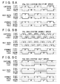
FIGs 5 to 8 is diagrams explaining examples of the capture
rate, the REC rate, and the format rate in each mode.
FIG. 5 shows examples in the case where the format rate
is "50i" (PAL system). FIG. 5A shows an example in the case
of the normal-speed mode (one-time speed). FIG. 5B shows an
example in the case of the high-speed mode (double speed). FIG.
5C shows an example in the case of the low-speedmode (half speed) .
That is, FIG. 5A shows the example of a relationship between
each value of the capture rate, the REC rate, and the format
rate, and field images at the time of generation, recording,
and playback, in the case where the imaging record apparatus
11 operates with the PAL systemand the user selects the interlaced
mode 181 as the system mode 175 and the normal-speed mode 185
as the speed mode 176. FIG. 5B shows the example of a relationship
between each value of the capture rate, the REC rate, and the
format rate, and field images at the time of generation, recording,
and playback, in the case where the imaging record apparatus
11 operates with the PAL system and the user selects the interlaced
mode 181 as the system mode 175 and the high-speed mode 186 as
the speed mode 176. FIG. 5C shows the example of a relationship
between each value of the capture rate, the REC rate, and the
format rate, and field images at the time of generation, recording,
and playback, in the case where the imaging record apparatus
11 operates with the PAL systemand the user selects the interlaced
mode 181 as the system mode 175 and the low-speed mode 187 as
the speed mode 176.
In the case of FIG. 5A, the capture rate, the REC rate,
and the format rate are set to common "50i". That is, in this
case, the CCD 112 in the imaging record apparatus 11 generates
the first field images (A, C, and E) and the second field images
(B and D) alternately with frequency of 50 fields per second.
The record processing unit 121 records each field image at the
same field rate, and the playback processing unit 142 in the
playback output apparatus 12 plays back each field image at the
same field rate.
Thus, the playback output apparatus 12 outputs each field
image of the image data generated by the imaging record apparatus
11 over the same time by the normal playback.
In the case of FIG. 5B, the capture rate and the REC rate
are set to "100i" which is double the format rate "50i". That
is, in this case, the CCD 112 in the imaging record apparatus
11 shortens a time interval for capturing electric charge to
the half compared to that of FIG. 5A, and increases the number
of times of the photoelectric conversion processing per second
to the double, and generates the first field images (A, C, E,
G and J) and the second field images (B, D, F, H, and K) alternately
with frequency of 100 fields per second. The record processing
unit 121 records each field image at the field rate (100 fields
per second) . However, since the format rate is the same as in
FIG. 5A, the playback processing unit 142 in the playback output
apparatus 12 plays back each field image at the same field rate
(50 fields per second) as in FIG. 5A.
Thus, the playback output apparatus 12 outputs each field
image of the image data generated by the imaging record apparatus
11 over double the time by the normal playback. That is, in
this case, the images by the normal playback at the playback
output apparatus 12 is played back in slow motion. This kind
of imaging way is used at the time of imaging a fast-moving subj ect
such as sport imaging, movement of water droplets, etc.
In the case of FIG. 5C, the capture rate and the REC rate
are set to "25i" which is half the format rate "50i" . That is,
in this case, the CCD 112 in the imaging record apparatus 11
extends a time interval for capturing electric charge to the
double compared to that of FIG. 5A, and decreases the number
of times of the photoelectric conversion processing per second
to the half, and generates the first field images (A and C) and
the second field image (B) alternatelywith frequency of 25 fields
per second. The record processing unit 121 records each field
image at the field rate (25 fields per second). However, since
the format rate is the same as in FIG. 5A, the playback processing
unit 142 in the playback output apparatus 12 plays back each
field image at the same field rate (50 fields per second) as
in FIG. 5A.
Thus, the playback output apparatus 12 outputs each field
image of the image data generated by the imaging record apparatus
11 over half the time by the normal playback. That is, in this
case, the images by the normal playback at the playback output
apparatus 12 is played back in fast forward. This kind of imaging
way is used at the time of imaging change of a subject over long
time such as stationary observation and the like.
FIG. 6 shows examples in the case where the format rate
is "25p". FIG. 6A shows an example in the case of the normal-speed
mode (one-time speed). FIG. 6B shows an example in the case
of the high-speed mode (double speed). FIG. 6C shows an example
in the case of the low-speed mode (half speed). That is, FIG.
6A shows the example of a relationship between each value of
the capture rate, the REC rate, and the format rate, and field
images at the time of generation, recording, and playback, in
the case where the imaging record apparatus 11 can generate and
record a progressive image (the format rate is set to "25p")
and the user selects the progressive mode 182 as the system mode
175 and the normal-speed mode 185 as the speed mode 176. FIG.
6B shows the example of a relationship between each value of
the capture rate, the REC rate, and the format rate, and field
images at the time of generation, recording, and playback, in
the case where the imaging record apparatus 11 can generate and
record a progressive image (the format rate is set to "25p")
and the user selects the progressive mode 182 as the system mode
175 and the high-speed mode 186 as the speed mode 176. FIG.
6C shows the example of a relationship between each value of
the capture rate, the REC rate, and the format rate, and field
images at the time of generation, recording, and playback, in
the case where the imaging record apparatus 11 can generate and
record a progressive image (the format rate is set to "25p")
and the user selects the progressive mode 182 as the system mode
175 and the low-speed mode 187 as the speed mode 176.
In the case of FIG. 6A, the capture rate, the REC rate,
and the format rate are set to common "25p". That is, in this
case, the CCD 112 in the imaging record apparatus 11 generates
frame images (A, B, and C) with frequency of 25 frames per second.
The record processing unit 121 records each frame image at the
same frame rate, and the playback processing unit 142 in the
playback output apparatus 12 plays back each frame image at the
same frame rate.
Thus, the playback output apparatus 12 outputs each frame
image of the image data generated by the imaging record apparatus
11 over the same time by the normal playback.
In the case of FIG. 6B, the capture rate and the REC rate
are set to "50p" which is double the format rate "25p". That
is, in this case, the CCD 112 in the imaging record apparatus
11 shortens a time interval for capturing electric charge to
the half compared to that of FIG. 6A, and increases the number
of times of the photoelectric conversion processing per second
to the double, and generates frame images (A to E) with frequency
of 50 frames per second. The record processing unit 121 records
each frame image at the frame rate (50 frames per second).
However, since the format rate is the same as in FIG. 6A, the
playback processing unit 142 in the playback output apparatus
12 plays back each frame image at the same frame rate (25 frames
per second) as in FIG. 6A.
Thus, the playback output apparatus 12 outputs each frame
image of the image data generated by the imaging record apparatus
11 over double the time by the normal playback.
In the case of FIG. 6C, the capture rate and the REC rate
are set to "12.5p" which is half the format rate "25p". That
is, in this case, the CCD 112 in the imaging record apparatus
11 extends a time interval for capturing electric charge to the
double compared to that of FIG. 6A, and decreases the number
of times of the photoelectric conversion processing per second
to the half, and generates frame images (A and B) with frequency
of 12.5 frames per second. The recordprocessingunit 121 records
each frame image at the frame rate (12.5 frames per second).
However, since the format rate is the same as in FIG. 6A, the
playback processing unit 142 in the playback output apparatus
12 plays back each frame image at the same frame rate (25 frames
per second) as in FIG. 6A.
Thus, the playback output apparatus 12 outputs each frame
image of the image data generated by the imaging record apparatus
11 over half the time by the normal playback.
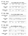
FIG. 7 shows examples in the case where the format rate
is "50i" and the image data is recorded with the PSF system.
FIG. 7A shows an example in the case of the normal-speed mode
(one-time speed) . FIG. 7B shows an example in the case of the
high-speed mode (double speed). FIG. 7C shows an example in
the case of the low-speed mode (half speed). That is, FIG. 7A
shows the example of a relationship between each value of the
capture rate, the REC rate, and the format rate, and field images
at the time of generation, recording, and playback, in the case
where the imaging record apparatus 11 can record PAL-system image
data (the format rate is set to "50i") and the user selects the
PSF system mode 183 as the system mode 175 and the normal-speed
mode 185 as the speed mode 176. FIG. 7B shows the example of
a relationship between each value of the capture rate, the REC
rate, and the format rate, and field images at the time of
generation, recording, and playback, in the case where the
imaging record apparatus 11 can record PAL-system image data
(the format rate is set to "50i") and the user selects the PSF
system mode 183 as the system mode 175 and the high-speed mode
186 as the speed mode 176. FIG. 7C shows the example of a
relationship between each value of the capture rate, the REC
rate, and the format rate, and field images at the time of
generation, recording, and playback, in the case where the
imaging record apparatus 11 can record PAL-system image data
(the format rate is set to "50i") and the user selects the PSF
system mode 183 as the system mode 175 and the low-speed mode
187 as the speed mode 176.
In the case of FIG. 7A, the capture rate is set to "25p",
and the REC rate and the format rate are set to "50i" of the
PAL system. That is, in this case, the CCD 112 in the imaging
record apparatus 11 generates frame images (A, B, and C) with
frequency of 25 frames per second. The signal processing unit
114 generates the first field images (odd fields) (A1, B1, and
C1) and the second field images (even fields) (A2, B2, and C2)
from each frame image. The record processing unit 121 records
each field image in sequence at the field rate (50 fields per
second) corresponding to the frame rate (25 frames per second)
which is set as the capture rate (i.e. , one frame makes two fields) .
The playback processing unit 142 in the playback output apparatus
12 plays back each field image at the same field rate (50 fields
per second).
In this case, as shown in FIG. 7A, one frame image generates
two field images. For example, the frame image A generates the
first field image A1 and the second field image A2. That is,
in this case, the timing when the image is generated (the timing
when electric charge is captured at the CCD 112) is the same
between the first field image and the second field image which
correspond with each other. Therefore, unlike in FIG. 5A, the
image data in this case, after the playback, can be converted
into the progressive system again (field images are combined
into a frame image).
In the case of FIG. 7B, the REC rate is set to "100i" which
is double the format rate "50i", and the capture rate is set
to "50p" corresponding to the REC rate. That is, in this case,
the CCD 112 in the imaging record apparatus 11 shortens a time
interval for capturing electric charge to the half compared to
that of FIG. 7A, and increases the number of times of the
photoelectric conversion processing per second to the double,
and generates frame images (A to E) with frequency of 50 frames
per second. The signal processing unit 114 generates the first
field images (odd fields) (A1, B1, C1, D1, and E1) and the second
field images (even fields) (A2, B2, C2, D2, and E2) from each
frame image. The record processing unit 121 records each field
image in sequence at the field rate (100 fields per second)
corresponding to the frame rate (50 frames per second) which
is set as the capture rate. The playback processing unit 142
in the playback output apparatus 12 plays back each field image
at the same field rate (50 fields per second) as in FIG. 7A.
Thus, the playback output apparatus 12 outputs each field
image of the image data recorded by the imaging record apparatus
11 over double the time by the normal playback.
In the case of FIG. 7C, the REC rate is set to "25i" which
is half the format rate "50i", and the capture rate is set to
"12.5p" corresponding to the REC rate. That is, in this case,
the CCD 112 in the imaging record apparatus 11 extends a time
interval for capturing electric charge to the double compared
to that of FIG. 7A, and decreases the number of times of the
photoelectric conversion processing per second to the half, and
generates frame images (A and B) with frequency of 12.5 frames
per second. The signal processing unit 114 generates the first
field images (odd fields) (A1 and B1) and the second field images
(even fields) (A2 and B2) from each frame image. The record
processing unit 121 records each field image in sequence at the
field rate (25 fields per second) corresponding to the frame
rate (12.5 frames per second) which is set as the capture rate.
The playback processing unit 142 in the playback output apparatus
12 plays back each field image at the same field rate (50 fields
per second) as in FIG. 7A.
Thus, the playback output apparatus 12 outputs each field
image of the image data recorded by the imaging record apparatus
11 over half the time by the normal playback.
FIG. 8 shows examples in the case where the format rate
is "60i" and the image data is recorded with a 2-3 pull-down
system. FIG. 8A shows an example in the case of the normal-speed
mode (one-time speed). FIG. 8B shows an example in the case
of the high-speed mode (double speed). FIG. 8C shows an example
in the case of the low-speed mode (half speed). That is, FIG.
8A shows the example of a relationship between each value of
the capture rate, the REC rate, and the format rate, and field
images at the time of generation, recording, and playback, in
the case where the format rate is set to "60i" and the user selects
the pull-down systemmode 184 (2-3 pull-down system) as the system
mode 175 and the normal-speed mode 185 as the speed mode 176.
FIG. 8B shows the example of a relationship between each value
of the capture rate, the REC rate, and the format rate, and field
images at the time of generation, recording, and playback, in
the case where the format rate is set to "60i" and the user selects
the pull-down systemmode 184 (2-3 pull-down system) as the system
mode 175 and the high-speed mode 186 as the speed mode 176. FIG.
8C shows the example of a relationship between each value of
the capture rate, the REC rate, and the format rate, and field
images at the time of generation, recording, and playback, in
the case where the format rate is set to "60i" and the user selects
the pull-down systemmode 184 (2-3 pull-down system) as the system
mode 175 and the low-speed mode 187 as the speed mode 176.
In the case of FIG. 8A, the capture rate is set to "24p",
and the REC rate and the format rate are set to "60i" of the
NTSC system. That is, in this case, the CCD 112 in the imaging
record apparatus 11 generates frame images (A and B) with
frequency of 24 frames per second. The signal processing unit
114 generates the first field images (odd fields) (A1 and B1)
and the second field images (even fields) (A2 and B2) in the
order shown in FIG. 8A from each frame image. The record
processing unit 121 records each field image in sequence at the
field rate (60 fields per second) corresponding to the frame
rate (24 frames per second) which is set as the capture rate
(i.e., two frames make five fields). The playback processing
unit 142 in the playback output apparatus 12 plays back each
field image at the same field rate (60 fields per second).
Thus, the image data based on a different system and rate
such as movie film can conform to a TV broadcasting standard
such as the NTSC system.
In the case of FIG. 8B, the REC rate is set to "120i" which
is double the format rate "60i", and the capture rate is set
to "48p" corresponding to the REC rate. That is, in this case,
the CCD 112 in the imaging record apparatus 11 shortens a time
interval for capturing electric charge to the half compared to
that of FIG. 8A, and increases the number of times of the
photoelectric conversion processing per second to the double,
and generates frame images (A to D) with frequency of 48 frames
per second. The signal processing unit 114 generates the first
field images (odd fields) (A1, B1, C2, and D2) and the second
field images (even fields) (A2, B2, C1, and D1) in the order
shown in FIG. 8B from each frame image. The record processing
unit 121 records each field image in sequence at the field rate
(120 fields per second) corresponding to the frame rate (48 frames
per second) which is set as the capture rate (i.e., two frames
make five fields). The playback processing unit 142 in the
playback output apparatus 12 plays back each field image at the
same field rate (60 fields per second) as in FIG. 8A.
Thus, the playback output apparatus 12 outputs each field
image of the image data recorded by the imaging record apparatus
11 over double the time by the normal playback.
In the case of FIG. 8C, the REC rate is set to "30i" which
is half the format rate "60i", and the capture rate is set to
"12p" corresponding to the REC rate. That is, in this case,
the CCD 112 in the imaging record apparatus 11 extends a time
interval for capturing electric charge to the double compared
to that of FIG. 8A, and decreases the number of times of the
photoelectric conversion processing per second to the half, and
generates frame images (A and B) with frequency of 12 frames
per second. The signal processing unit 114 generates the first
field images (odd fields) (A1 and B1 ) and the second field images
(even fields) (A2 and B2) in the order shown in FIG. 8C from
each frame image. The record processing unit 121 records each
field image in sequence at the field rate (30 fields per second)
corresponding to the frame rate (12 frames per second) which
is set as the capture rate (i.e., two frames make five fields) .
The playback processing unit 142 in the playback output apparatus
12 plays back each field image at the same field rate (60 fields
per second) as in FIG. 8A.
Thus, the playback output apparatus 12 outputs each field
image of the image data recorded by the imaging record apparatus
11 over half the time by the normal playback.
The control unit 21 in the imaging record apparatus 11
controls the imaging unit 22 and the record unit 23 as described
above, based on the inputted input imaging record mode
instruction and the apparatus information 102A stored in the
ROM 102, and also provides the input imaging record mode
instruction and the apparatus information 102A to the rate
information creation unit 24. The rate information creation
unit 24 creates the capture rate, the REC rate, and the format
rate base on the input imaging record mode instruction and the
apparatus information 102A provided from the control unit 21,
and provides them to the record unit 23. The record unit 23
relates the rate information provided from the rate information
create unit 24 to the image data and the audio data provided
from the imaging unit 22, and records it onto the optical disc
13.
Thus, in the case where the playback output apparatus 12
plays back the image data and the audio data recorded on the
optical disc 13, the playback output apparatus 12 can display
the rate information at the time of imaging and recording such
as the capture rate and the REC rate on the monitor, as well
as acquiring the rate information required for the playback
processing and the output processing. That is, the imaging
record apparatus 11 can provide the rate information to the
playback output apparatus 12 by recording the rate information
on the optical disc 13 as described above.
Next, specific flows of the above processing will be
described.
For example, when the imaging record apparatus 11 is turned
on, the main control unit 101 performs imaging record control
processing to control each unit in the imaging record apparatus
11. Referring to flowcharts in FIG. 9 and FIG. 10, the imaging
record control processing will be described.
First, the main control unit 101 performs initialization
processing to initialize a state of each unit at step S1, and
initializes an imaging record control setting which is stored
in, for example, the RAM 103 or the like, at step S2. The imaging
record control setting is setting information for the main
control unit 101 to control the imaging unit 22 and the record
unit 23, and includes, for example, the apparatus information
102A stored in the ROM 102 and the input imaging record mode
instruction inputted by the user. That is, the main control
unit 101 controls the imaging unit 22 and the record unit 23
with the capture rate and the REC rate determined based on the
imaging record control setting.
After completing step S2, the main control unit 101 controls
the input unit 104 at step S3 to determine whether or not the
input unit 104 has received the input imaging record mode 172.
If the main control unit 101 determines that the input unit 104
has received the input imaging record mode 172, the process moves
to step S4 where the main control unit 101 reads out the apparatus
information 102A stored in the ROM 102 and determines the capture
rate and the REC rate according to the apparatus information
102A and the input imaging record mode inputted from the input
unit 104 and updates the imaging record control setting.
After completing step S4, the main control unit 101
determines at step S5 whether the imaging unit 22 and the record
unit 23 are currently performing the imaging processing and the
record processing. That is, the main control unit 101 determines
whether the subject is in the process of being imaged. If the
main control unit 101 determines that the subj ect is in the process
of being imaged (the imaging processing and the record processing
are being performed), the process moves to step S6 where the
main control unit 101 applies the updated data of the imaging
record control setting to the control of the imaging unit 22
and the record unit 23. Further, at step S7, the main control
unit 101 provides the apparatus information 102A read from the
ROM 102 and the inputted input imaging record mode to the rate
information creation unit 24 and makes the rate information
creation unit 24 create the rate information (the capture rate,
the REC rate, and the format rate) andprovide the rate information
to the record unit 23. At step S8, the main control unit 101
controls the record unit 23 to make the record unit 23 relate
the rate information to the image data and the audio data and
record it onto the optical disc 13. After completing step S8,
the main control unit 101 moves the process to step S11 in FIG.
10.
Further, at step S5 in FIG. 9, if the main control unit
101 determines that the imaging processing and the record
processing are not being performed, the main control unit 101
omits steps 6 to 8 and moves the process to step S11 in FIG.
10. Furthermore, at step S3 in FIG. 9, if the main control unit
101 determines that the input unit 104 has not received the input
imaging record mode, the main control 101 omits steps 4 to 8
and moves the process to step S11 in FIG. 10. That is, only
during imaging, the main control unit 101 applies the inputted
input imaging record mode 172 to the control of the imaging unit
22 and the record unit 23 and makes the rate information creation
unit 24 create the new rate information and makes the record
unit 23 relate the rate information to the image data and the
audio data and record it onto the optical disc 13. If not during
imaging, the main control unit 101 does not perform the update
to the control of the imaging unit 22 and the record unit 23
or the creation of the new rate information, etc., which respond
to the input imaging record mode 172. Further, if the input
imaging record mode 172 is not inputted, the main control unit
101 does not update the imaging record control setting either.
At step S11 in FIG. 10, the main control unit 101 controls
the input unit 104 to determine whether the input unit 104 has
received an imaging record start instruction. If the main
control unit 101 determines that the input unit 104 has received
the imaging record start instruction, the main control unit 101
controls the imaging unit 22 and the record unit 23 to make the
imaging unit 22 and the record unit 23 initiate the imaging
processing and the record processing at step S12 based on the
imaging record control setting stored in the RAM 103. Further,
at step S13, the main control unit 101 provides the input imaging
record mode 172 and the apparatus information 102A to the rate
information creation unit 24 and makes the rate information
creation unit 24 create the rate information (the capture rate,
the REC rate, and the format rate) andprovide the rate information
to the record unit 23. At step S14, the main control unit 101
controls the record unit 23 to make the record unit 23 relate
the rate information to the image data and the audio data and
record it onto the optical disc 13.
After completing step S14, the main control unit 101 moves
the process to step S15 . Further, at step S11, if the main control
unit 101 determines that the input unit 104 has not received
the imaging record start instruction, the main control unit 101
omits steps 12 to 14 and moves the process to step S15.
At step S15, the main control unit 101 determines whether
the input unit 104 has receivedan imaging record end instruction.
If the main control unit 101 determines that the input unit 104
has received the imaging record end instruction, the main control
unit 101 controls the imaging unit 22 and the record unit 23
to make the imaging unit 22 and the record unit 23 end the imaging
processing and the record processing at step S16 and moves the
process to step S17. Further, at step S15, if the main control
unit 101 determines that the input unit 104 has not received
the imaging record end instruction, the main control unit 101
omits steps 16 and moves the process to step S17.
At step S17, the main control unit 101 determines whether
to end the imaging record control processing. If the main control
unit 101 determines that it does not end the imaging record control
processing, the process returns to step S3 in FIG. 9 and repeats
from step S3. Further, at step S17 in FIG. 10, if the main control
unit 101 determines that it ends the imaging record control
processing, the main control unit 101 moves the process to step
S18 and performs end processing to end the imaging record control
processing.
That is, when the imaging processing and the record
processing are initiated or the input imaging record mode is
changed by the user, the main control unit 101 makes the rate
information creation unit 24 create the updated new rate
information (the capture rate, the REC rate, and the format rate)
and makes the record unit 23 relate the rate information to the
image data and the audio data and record it onto the optical
disc 13.
By this control of the main control unit 101, as shown
in FIG. 11, a transition point table 191 which shows a transition
point (frame) of the capture rate, the REC rate, and the format
rate is recorded on the optical disc 13.
In the case of FIG. 11, a transition point of each rate
information of the capture rate, the REC rate, and the format
rate is related to a frame number in the transition point table
191. For example, the capture rate, the REC rate, and the format
rate that correspond to the frame number "0" (i.e., a start frame)
are all "50i" . The capture rate and the REC rate that correspond
to the frame number "1000" are "100i" and a format rate is "50i" .
The capture rate and the REC rate that correspond to the frame
number "2000" are "25i" and the format rate is "50i".
That is, the transition point table 191 shows that the
imaging record apparatus 11 generates the image data
corresponding to the PAL system and the user specifies the
interlaced mode 181 and the normal-speed mode 185 as the input
imaging recordmode 172 at the start of imaging, and the interlaced
mode 181 and the high-speed mode 186 (double speed) as the input
imaging record mode 172 at the 1000th frame, and the interlaced
mode 181 and the low-speed mode 187 (half speed) as the input
imaging record mode 172 at the 2000th frame.
In FIG. 11, the transition point of each rate information
is related to the frame number; however, this is not limited
to the frame number, but it may be related to a field number
or a time code.
Further, in the optical disc 13, the rate information may
be recorded as metadata corresponding to the audio data and the
image data in a predetermined unit as shown in FIG. 12A, or may
be recorded as metadata corresponding to the audio data the and
image data obtained by one-time imaging processing (processing
from imaging start through imaging end) (hereinafter referred
toas "clip") as shown in FIG. 12B, or maybe recorded in a dif ferent
area from that of the audio data and the image data as shown
in FIG. 12C.
In the case of FIG. 12A, as metadata 203 corresponding
to the audio data 201 and the image data 202 in units of frames
for example, the capture rate 41, the REC rate 42, and the format
rate 43 are recorded. That is, in this case, in the optical
disc 13, the audio data and the image data are divided in units
of frames, and a frame of audio data 201, a frame of image data
202, their metadata 203, a subsequent frame of audio data 204,
a subsequent frame of audio data 205, and their metadata 206
are recorded in the above order. Each metadata corresponds to
the preceding image data and audio data, and the capture rate
41, the REC rate 42, and the format rate 43 also corresponds
to the preceding image data and audio data.
In the case of FIG. 12B, as the metadata corresponding
to the audio data and the image data in units of clips, the capture
rate, the REC rate, and the format rate are recorded. That is,
in this case, in the optical disc 13, audio data and image data
in units of frames are arranged in a predetermined order such
as the audio data 211, the image data 212, the audio data 213,
the image data 214, the audio data 215, and the image data 216,
and a clip of audio data and image data is collected. As the
metadata 217 corresponding to a clip of audio data and image
data, the capture rate 41, the REC rate 42, and the format rate
43 are recorded. After the metadata 217, another clip data such
as the audio data 218 and the image data 219 is recorded
subsequently.
In the case of FIG. 12C, the capture rate, the REC rate,
and the format rate are recorded in a different area from that
of the audio data and the image data. That is, in this case,
in the optical disc 13, the audio data and the image data are
recorded in a first area of a predetermined memory area as the
audio data 211 to the image data 216, and the metadata 241 including
the capture rate 41, the REC rate 42, and the format rate 43
of the corresponding rate information is recorded in a second
area which is a different memory area from the first area. In
this case, a UMID (Unique Material IDentifier) 231 is assigned
to the audio data and the image data in a predetermined unit,
and the metadata 241 includes UMID information 242 which
specifies the UMID. That is, in this case, each rate information
is related by the UMID, and the metadata 241 is related to the
audio data and the image data by the UMID 231 described in the
UMID information 242.
Further, the rate information (the capture rate, the REC
rate, and the format rate) may be recorded on a different record
medium than the image data and the audio data are recorded on.
In this case, in the same way as in FIG. 12C, the rate information
is related to the image data and the audio data using an identifier
such as the UMID or the like.
Next, referring to FIG. 13, rate information creation
processing which is performed by the rate information creation
unit 24 controlled by the main control unit 101 will be described.
The rate information creation unit 24, which is provided
with the apparatus information 102A and the input imaging record
mode and instructed to create the rate information by the main
control unit 101, finds the format rate at step 31 based on the
provided apparatus information. The rate information creation
unit 24 finds the REC rate at step S32 based on the apparatus
information and the input imaging record mode and the capture
rate at step S33 based on the apparatus information and the input
imaging record mode.
Further, at step S34, the rate information creation unit
24 provides the record unit 23 with the capture rate, the REC
rate, and the format rate obtained through steps 31 to 33 as
the rate information, and the rate information creation
processing ends.
For example, in the case of FIG. 5A, since the format rate
is set to "50i" in the apparatus information 102A, the rate
information creation unit 24 determines that the format rate
is "50i". Further, in the case of FIG. 5A, since the interlace
mode and the normal-speed mode are specified as the input imaging
record mode, the rate information creation unit 24 determines
that the capture rate and the REC rate is the same "50i" as the
format rate. Thus, the rate information creation unit 24 can
determine the rate informationbasedon the apparatus information
and the input imaging record mode and can make the optical disc
13 record it. That is, the imaging record apparatus 11 can
provide the rate information created based on the user input
and the like to the playback output apparatus 12.
Next, operation of the playback output apparatus will be
described.
The main control unit 131 in the playback output apparatus
12 performs playback output control processing when, for example,
the power is turned on or the optical disc 13 on which the rate
information along with the image data and the audio data is
recorded is mounted onto a drive (not shown).
Referring to FIG. 14 and FIG. 15, the playback output control
processing will be described.
First, the main control unit 131 in the playback output
apparatus 12 performs initialization processing to initialize
a state of each unit at step S51, and initializes a playback
output control setting which is information regarding operation
setting of each unit controlled by the main control unit 131,
at step 552. At step S53, the main control unit 131 initializes
a display setting of the rate information (for example,
no-display setting).
At step S54, the main control unit 131 determines whether
the playback processing, the image audio processing, and the
output processing are being performed. If the main control unit
131 determines that they are not being performed, the main control
unit 131 controls the input unit 134 at step S55 to determine
whether it has received a rate information display instruction
inputted by the user. If the main control unit 131 determines
that the input unit 134 has received the rate information display
instruction (the instruction of display or no display) from the
user, the main control unit 131 moves the process to step S56
where the main control unit 131 updates the display setting of
the rate information based on the inputted instruction and moves
the process to step S57. Further, at step S55, if the main control
unit 131 determines that the input unit 134 has not received
the rate information display instruction, the main control unit
131 omits step S56 and moves the process to step S57.
At step S57, the main control unit 131 controls the input
unit 134 to determine whether it has received a playback output
start instruction inputted by the user. If the main control
unit 131 determines that the input unit 134 has received the
playback output start instruction, the process moves to step
S58 where the main control unit 131 controls the drive control
unit 143 in the playback unit 52 to make it read out the rate
information. The pickup unit 141 is controlled by the drive
control unit 143 to read the rate information corresponding to
desired image data (and audio data) from the optical disc 13
mounted on the drive (not shown) and provide the rate information
to the rate information determination unit 55.
At step S59, the main control unit 131 controls the rate
information determination unit 55 to make the rate information
determination unit 55 determine necessity of data conversion
processing of the image data at the data conversion unit 152
based on the rate information provided from the pickup unit 141,
and acquires the determination result and the rate information.
Further, at step S60, the main control unit 131 updates the
playback output control setting based on the determination result
and the format rate. At step 61, the main control unit 131
controls operation of the playback processing unit 142 and the
drive control unit 143 in the playback unit 52, the signal
processing unit 151 in the image audio processing unit 53, and
the monitor 161 and the speaker 162 in the output unit 54 to
make them initiate the playback processing, the image audio
processing, and the output processing based on the playback
output control setting and the display setting of the rate
information.
By this processing, the playback processing unit 142 in
the playback unit 52 can initiate the playback processing based
on the rate information. That is, the playback processing unit
142 can initiate the normal playback at the format rate specified
by the imaging record apparatus 11.
Further, the data conversion unit 152 in the signal
processing unit 151 can initiate the data conversion processing
as necessary by this control of the main control unit 131. For
example, as described later, in the case where the image data
recorded on the optical disc 13 is the image data according to
the PSF system, if the rate information determination unit 55
determines that the data conversion is required, the data
conversion unit 152 acquires the determination result by the
playback output control setting and can initiate processing of
converting the image data from the interlaced system to the
progressive system. Further, if the data conversion unit 152
acquires the determination result that indicates no data
conversion, the data conversion unit 152 can also initiate
processing of outputting the provided image data without
conversion.
Further, the output information creation unit 153
determines whether to output the provided rate information
through the monitor 161 based on the display setting of the rate
information provided from the main control unit 131. If the
output information creation unit 153 determines that it outputs
the rate information, the output information creation unit 153
creates an image for displaying the rate information and can
initiate processing of superimposing it on the image data read
from the optical disc 13.
Further, the monitor 161 and the speaker 162 in the output
unit 54 can initiate processing of outputting the image and the
audio provided from the image audio processing unit 53 by the
control of the main control unit 131.
As described above, the main control unit 131 which has
made each unit initiate each processing moves the process to
step 80 in FIG. 15. Further, at step S57 in FIG. 14, if the
main control unit 131 determines that the input unit 134 has
not received the playback output start instruction, the main
control unit 131 omits steps S58 to S61 and moves the process
to step S80 in FIG. 15.
At step S80 in FIG. 15, the main control unit 131 determines
whether to end the playback output control processing. If the
main control unit 131 determines that it does not end the playback
output control processing, the process returns to step S54 in
FIG. 14 and repeats from step S54. At step S80 in FIG. 15, if
the main control unit 131 determines that it ends the playback
output control processing, the main control unit 131 performs
end processing at step S81 to end the playback output control
processing.
Further, at step S54 in FIG. 14, if the main control unit
131 determines that the playback processing, the image audio
processing, and the output processing are being performed, the
main control unit 131 moves the process to step S71 in FIG. 15
and then controls input unit 134 to determine whether it has
received a rate information display instruction. If the main
control unit 131 determines that the input unit 134 has received
the rate information display instruction, the main control unit
131 updates the display setting of the rate information at step
S72 based on the received instruction. At step S73, the main
control unit 131 controls each unit such that the playback
processing, theimageaudioprocessing, andtheoutputprocessing
are performed, and the rate information is displayed or not
displayed, based on the updated display setting of the rate
information.
After completing step S73, the main control unit 131 moves
the process to step S74 . Further, at step S71, if the main control
unit 131 determines that the input unit 134 has not received
the rate information display instruction, the main control unit
131 omits steps S72 and S73 and moves the process to step S74.
At step S74 , if the main control unit 131 determines whether
or not the image data read from the optical disc 13 corresponds
to the transition point of the rate information and the rate
information corresponding to the image data has changed. If
the main control unit 131 determines that the rate information
has changed, the main control unit 131 moves the process to step
S75 and then controls the rate information determination unit
55 to determine whether the data conversion is required. At
step 76, based on the determination result and the format rate,
the main control unit 131 updates the playback output control
setting. At step S77, based on the updated playback output
control setting, the playback processing, the image audio
processing, and the output processing are performed.
By this control of the main control unit 131, the playback
processing unit 142 can perform the normal playback at the format
rate specified by the imaging record apparatus 11 based on the
rate information, and the data conversion unit 152 can perform
the data conversion processing of the image data as necessary,
and the output unit 54 can perform the processing of outputting
the image and the audio provided from the image audio processing
unit 53.
After completing step S77, the main control unit 131 moves
the process to step S78. Further, at step S74, if the main control
unit 131 determines that the rate information corresponding to
the read image data has not changed, the main control unit 131
omits steps 75 to 77 and moves the process to step S78.
At step S78, the main control unit 131 controls the input
unit 134 to determine whether it has received a playback output
end instruction inputted by the user. If the main control unit
131 determines that the input unit 134 has received the playback
output end instruction, the process moves to step S79 where the
main control unit 131controls each unit such that the playback
processing, theimageaudioprocessing, andtheoutputprocessing
are ended, and moves the process to step S80. Further, at step
S78, if the main control unit 131 determines that the input unit
134 has not received the playback output end instruction, the
main control unit 131 omits step S79 and moves the process to
step S80.
Description of steps S80 and S81 is omitted here since
it is the same as the above-mentioned.
As described above, by the playback output control
processing of the main control unit 131, each unit in the playback
output apparatus 12 can perform more effective playback
processing, image audio processing, output processing, and the
like based on the rate information recorded on the optical disc
13.
Next, determination processing performed by the rate
information determination unit 55 will be described with
reference to a flowchart in FIG. 16.
When the rate information determination unit 55 is provided
with the rate information from the pickup unit 141 and instructed
to initiate the determination processing by the main control
unit 131, the rate information determination unit 55 initiates
the determination processing and, at step S101, refers to the
rate information to determine the format rate. At step S102,
the rate information determination unit 55 refers to the rate
information to determine the system mode and the speed mode,
and at step S103, determines the necessity of the data conversion
at the data conversion unit 152 based on the determination result
of the system mode.
Further, at step S104, the rate information determination
unit 55 outputs the determination results along with the rate
information to the main control unit 131 and ends the
determination processing.
By the determination processing, the playback output
apparatus 12 can display the rate information recorded on the
optical disc 13 to the user and can perform the normal playback
at the format rate specified by the imaging record apparatus
11 and can convert the playback data as necessary. That is,
the playback output apparatus 12 can perform more effective
playback processing, image audio processing, output processing,
and the like based on the rate information recorded on the optical
disc 13.
A specific example of the determination processing in steps
S102 and S103 will be described with reference to relationship
between the rate information and the imaging record mode shown
in FIG. 17.
A table 215 shown in FIG. 17 shows a list of imaging record
modes corresponding to the settings of the format rate, the REC
rate, and the capture rate.
The rate information determination unit 55 can determine
the system mode in FIG. 4 by comparing the system mode of the
format rate with that of the capture rate. For example, in the
case where the format rate is set to the interlaced system such
as "50i" and the capture rate is set to the interlaced system
(e.g., an example from the first line to the fourth line in the
table 251) , the rate information determination unit 55 determines
that the interlaced mode is specified as the system mode in FIG.
4 since the interlaced image data obtained by imaging is recorded
with the same system. Further, for example, in the case where
the format rate is set to the interlaced system such as "50i"
or "60i" and the capture rate is set to the progressive system
(e.g., examples from the fifth line to the eighth line and from
thirteenth line to sixteenth line in the table 251), the rate
information determination unit 55 determines that the PSF system
mode or the pull-down system mode is specified as the system
mode in FIG. 4 since the progressive image data obtainedby imaging
is converted into the interlaced image data to be recorded.
Furthermore, for example, in the case where the format rate is
set to the progressive system such as "25p" and the capture rate
is also set to the progressive system (e.g., an example from
the ninth line to the twelfth line in the table 251), the rate
information determination unit 55 determines that the
progressive mode is specified as the system mode in FIG. 4 since
the progressive image data obtained by imaging is recorded with
the same system.
Further, in the case of the interlaced mode, the rate
information determination unit 55 can determine the speed mode
in Fig. 4 by comparing the field rate of the format rate with
that of the REC rate. For example, in the case where the format
rate and the REC rate are set to "50i" (e.g., an example of the
first line in the table 251), the rate information determination
unit 55 determines that the normal-speed mode is specified as
the speed mode since the format rate and the REC rate are the
same. Further, for example, in the case where the format rate
is set to "50i" and the REC rate is set to "100i" (e.g., an example
of the second line in the table 251), the rate information
determination unit 55 determines that the high-speed mode is
specified as the speed mode since the REC rate is higher than
the format rate. Furthermore, for example, in the case where
the format rate is set to "50i" and the REC rate is set to "25i"
(e.g. , an example of the third line in the table 251), the rate
information determination unit 55 determines that the low-speed
mode is specified as the speed mode since the REC rate is lower
than the format rate. Moreover, in the case where the speed
mode is specified with the rate, if the format rate is set to
"50i" and the REC rate is "Ni" (e.g., an example of the fourth
line in the table 251), the speed mode is an "N/50" times speed
since the REC rate is "N/50" times the format rate.
In the case of the progressive mode, the rate information
determination unit 55 can determine the speed mode in Fig. 4
in the same way as in the interlaced mode by comparing the frame
rate of the format rate with that of the REC rate. For example,
in the case where the format rate and the REC rate are set to
"25p" (e.g., an example of the ninth line in the table 251),
the rate information determination unit 55 determines that the
normal-speed mode is specified as the speed mode. Further, in
the case where the format rate is set to "25p" and the REC rate
is set to "50p" (e.g., an example of the tenth line in the table
251) , the rate information determination unit 55 determines that
the high-speed mode is specified as the speed mode . Furthermore,
in the case where the format rate is set to "25p" and the REC
rate is set to "12.5p" (e.g., an example of the eleventh line
in the table 251), the rate information determination unit 55
determines that the low-speed mode is specified as the speed
mode. Moreover, in the case where the speed mode is specified
with the rate, if the format rate is set to "25p" and the REC
rate is "Np", the speed mode is an "N/25" times speed.
Further, the rate information determination unit 55 can
determine whether the PSF system mode or the pull-down system
mode is specified as the system mode in FIG. 4 by comparing the
field rate of the REC rate with the frame rate of the capture
rate. For example, in the case where the REC rate is set to
"50i" and the capture rate is "25p" (e.g., an example of the
fifth line in the table 251) , the rate information determination
unit 55 determines that the PSF system mode is specified as the
system mode since the field rate of the REC rate corresponds
with the frame rate of the capture rate (the rate ratio of 2:1) .
Further, in the case where the REC rate is set to "100i" and
the capture rate is "50p", and the REC rate is set to "25i" and
the capture rate is "12.5p" (e.g., examples of the sixth line
and the seventh line in the table 251), the rate information
determination unit 55 determines that the PSF system mode is
also specified as the system mode. Moreover, in the case where
the speed mode is specified with the rate, if the field rate
of the REC rate is set to "2Ni" and the frame rate of the capture
rate is "Np" (e.g., an example of the eighth line in the table
251) , that is, the field rate of the REC rate is twice the frame
rate of the capture rate, the rate information determination
unit 55 determines that the PSF system mode is specified as the
system mode.
On the other hand, in the case where the field rate of
the REC rate does not correspond with the frame rate of the capture
rate (the rate ratio is not 2:1) (e.g., examples from the
thirteenth line to the sixteenth line in the table 251), the
rate information determination unit 55 determines that the
pull-down system mode is specified as the system mode. Further,
a pull-down ratio can be calculated from the ratio of the REC
rate and the capture rate.
Further, in the case of the PSF system mode or the pull-down
system mode, the rate information determination unit 55 can
determine the speed mode in Fig. 4 in the same way as in the
interlaced mode and the progressive mode by comparing the format
rate with the REC rate. Furthermore, in the case where the speed
mode is specifiedwith the rate, if the PSF systemmode is specified
as the system mode and the format rate is set to "50i" and the
REC rate is "2Ni" (e.g., an example of the eighth line in the
table 251) , the speed mode is an "N/25" times speed. Moreover,
in the case where the speed mode is specified with the rate,
if the pull-down system mode is specified as the system mode
and the format rate is set to "60i" and the REC rate is "Ri"
(e.g., an example of the sixteenth line in the table 251), the
speed mode is a "R/60" times speed.
The rate information determination unit 55 determines the
system mode and the speed mode in the above way at step S102
in FIG. 16. Further, in the case where the system mode determined
in the above way is the PSF system mode, the rate information
determination unit 55 determines that the data conversion unit
152 performs the data conversion processing.
According to the above description, the rate information
determination unit 55 determines the system mode and the speed
mode fromtherate information based on predetermined conditions .
However, for simplicity of the processing, the rate information
determination unit 55 may retain the table 251 shown in FIG.
17 beforehand and determine the imaging record mode to which
the rate information applies, referring to the table 251.
Further, the determination processing is performed under
the control of the main control unit 131 with each transition
point of the rate information.
Next, a description will be made of rate information display
control processing by the output information creation unit 153
in the signal processing unit 151 with reference to a flowchart
in FIG. 18.
When the output information creation unit 153 is provided
with the rate information and the display setting of the rate
information and instructed to initiate the rate information
display control processing by the main control unit 131, the
output information creation unit 153 determines at step S121
whether to display the rate information based on the provided
display setting of the rate information. If the output
information creation unit 153 determines that it displays the
rate information, the output information creation unit 153 moves
the process to step S122 and determines whether the image for
displaying the rate information already exists. If the output
information creation unit 153 determines that the image for
displaying the rate information does not exist, the output
information creation unit 153 moves the process to step S123
where the output information creation unit 153 creates the image
for displaying the rate information based on the provided rate
information and moves the process to step S126. At step S122,
if the output information creation unit 153 determines that the
image for displaying the rate information already exists since
the output information creation unit 153 has created the image
for displaying the rate information before and retains it, the
output information creation unit 153 omits step S123 and moves
the process to step S126.
Further, at step S121, if the output information creation
unit 153 determines that it does not display the rate information,
the output information creation unit 153 moves the process to
step S124 and determines whether the image for displaying the
rate information already exists. If the output information
creation unit 153 determines that the image for displaying the
rate information already exists since the output information
creation unit 153 has created the image for displaying the rate
information before and retains it, the output information
creation unit 153 moves the process to step S125 where the output
information creation unit 153 erases the retained image for
displaying the rate information and moves the process to step
S126. Further, at step 5124, if the output information creation
unit 153 determines that the image for displaying the rate
information does not exist, the output information creation unit
153 omits step S125 and moves the process to step S126.
At step S126, the output information creation unit 153
determines whether it has acquired the image data read from the
optical disc 13. If the output information creation unit 153
determines that it has acquired the image data read from the
optical disc 13, the output information creation unit 153
determines at step S127 whether the image for displaying the
rate information exists. If the output information creation
unit 153 determines that the image for displaying the rate
information exists, the output information creation unit 153
superimposes the image for displaying the rate information on
the image data at step S128 and moves the process to step S129.
At step S127, if the output information creation unit 153
determines that the image for displaying the rate information
does not exist, the output information creation unit 153 omits
step S128 and moves the process to step S129.
At step S129, the output information creation unit 153
outputs the image data and moves the process to step S130.
Further, at step S126, if the output information creation unit
153 determines that it has not acquired the image data read from
the optical disc 13, the output information creation unit 153
omits steps S127 to S129 and moves the process to step S130.
At step 130, the output information creation unit 153 determines
whether to end the rate information display control processing.
If the output information creation unit 153 determines that it
does not end the rate information display control processing,
the process returns to step S121 and repeats from step S121.
Further, if the output information creation unit 153 determines
that it ends the rate information display control processing,
the output information creation unit 153 moves the process to
step S131 where the output information creation unit 153 performs
end processing to end the rate information display control
processing.
The output information creation unit 153 performs the rate
information display control processing, in the above way. Thus,
the playback output apparatus 12 can display the rate information
recorded on the optical disc 13 to the user. That is, the playback
output apparatus 12 can perform more effective playback
processing, image audio processing, output processing, and the
like based on the rate information recorded on the optical disc
13.
Further, the imaging record mode determined at the rate
information determination unit 55 may be displayed instead of
the rate information. In this case as well, the same processing
as in the case of displaying the rate information is performed.
Thus, for example, in the table 251 in FIG. 17, the imaging record
mode corresponding to the rate information of the format rate,
the REC rate, and the capture rate is displayed on the monitor.
That is, the rate information and the imaging record mode are
the same meaning. It is desirable to display information that
is easier for the user to understand, or both of them may be
displayed, or the user may select which to display.
Next, the data conversion processing by the data conversion
unit 152 in the signal processing unit 151 will be described
with reference to a flowchart in FIG. 19.
The data conversion unit 152 determines at step S151 whether
it has acquired information regarding a data conversion setting.
If the data conversion unit 152 determines that it has acquired
the information regarding the data conversion setting, the data
conversion unit 152 moves the process to step S152 where the
data conversion unit 152 updates the retained data conversion
setting and moves the process to step S153. Further, at step
S151, if the data conversion unit 152 determines that it has
not acquired the information regarding the data conversion
setting, the data conversion unit 152 omits step S152 and moves
the process to step S153.
At step S153, the data conversion unit 152 determines
whether it has acquired the image dataplayedback from the optical
disc 13. If the data conversion unit 152 determines that it
has acquired the image data, the data conversion unit 152 moves
the process to step S154 and determines whether it converts the
acquired image data based on the data conversion setting. If
the data conversion unit 152 determines that it converts the
image data, the data conversion unit 152 converts the image data
at step S155 based on the data conversion setting and moves the
process to step S156. Further, at step S154, if the data
conversion unit 152 determines that it does not convert the image
data, the data conversion unit 152 omits step S155 and moves
the process to step S156.
At step 156, the data conversion unit 152 outputs the image
data. After outputting the image data, the data conversion unit
152 moves the process to step S157. Further, at step S153, if
the data conversion unit 152 determines that it has not acquired
the image data, the data conversion unit 152 omits steps S154
to S156 and moves the process to step S157.
At step S157, the data conversion unit 152 determines
whether to end the data conversion processing. If the data
conversion unit 152 determines that it does not end the data
conversion processing, the process returns to step S151 and
repeats from step S151. Further, if the data conversion unit
152 determines that it ends the data conversion processing, the
data conversion unit 152 performs end processing at step S158
to end the data conversion processing.
The data conversion unit 152 performs the data conversion
processing in the above way. Thus, the playback output apparatus
12 can play back the image data recorded on the optical disc
13 and change the system of the image data as necessary to output
it. That is, the playback output apparatus 12 can perform more
effective playback processing, image audio processing, output
processing, and the like based on the rate information recorded
on the optical disc 13.
Further, in the record playback system 1 in FIG. 1, the
image data and the audio data are provided from the imaging record
apparatus 11 to the playback output apparatus 12 through the
optical disc 13 which is a record medium; however, the record
medium is not limited to the optical disc, but any kind of medium
that is, for example, a magnetic record medium such as a magnetic
disk or a magnetic tape, a magneto-optical disk, or a
semiconductor memory suchas a flash memory or a RAM may be utilized.
Further, the image data and the audio data may be transmitted
to another apparatus without being recorded. In this case, as
shown below (for example, in FIG. 20), by configuring a
transmissionmediumbetweenatransmittingbufferandareceiving
buffer such that it is equivalent to the record medium, the REC
rate can be defined as in the case of the above explanation.
FIG. 2 0 shows an example of a communication system according
to the present invention.
A communication system 301 comprises an imaging apparatus
311 and an output apparatus 312 as shown in FIG. 20. The imaging
apparatus 311 is equipped with a communication unit 323 instead
of the record unit 23 in the imaging record apparatus 11 in FIG.
1 and connected with the output apparatus 312 through a network
313. The output apparatus 312 is equipped with a communication
unit 352 instead of the playback unit 52 in the playback output
apparatus 12 in FIG. 1 and connected with the imaging apparatus
311 through the network 313.
The communication unit 323 in the imaging apparatus 311
and the communication unit 352 in the output apparatus 312 include
a buffer 323A and a buffer 352A such as RAM respectively. The
communication unit 323 in the imaging apparatus 311 stores the
image data and the audio data provided from the imaging unit
22 and the rate information etc. provided from the rate
information creation unit in the buffer 323A temporarily, and
transmits these items of data to the output apparatus 312 at
a predetermined communication rate. The data transmitted from
the imaging apparatus 311 is provided to the output apparatus
312 through the network 313. The communication unit 352 in the
output apparatus 312 receives the provided data and stores it
in the buffer 352A temporarily. Further, the communication unit
352 reads out the data andprovides it to the image audioprocessing
unit 53 and the rate information determination unit 55 at a
predetermined rate as being controlled by the control unit 51.
That is, in a communication system 301, by regarding the
transmission medium between the buffer 323A in the communication
unit 323 in the imaging apparatus 311 and the buffer 352A in
the communication unit 352 in the output apparatus 312 as an
equivalent to the record medium in the record playback system
in FIG.. 1 (the optical disc 13), the same processing as in the
record playback system in FIG. 1 can be performed. That is,
in the case of the communication system 301 in FIG. 20, the capture
rate 41 refers to the data rate at the time of capturing the
image (generating the content data) at the imaging unit 22 in
the imaging apparatus 311 as in the case of FIG. 1(i.e., the
frame rate or the field rate of the image data obtained by the
photoelectric conversion processing). The REC rate 42 refers
to the data rate of the image data at the time of storing the
image data in the buffer 323A in the communication unit 323 (the
data rate at the time of transmitting the content data) (not
the transmission rate that indicates the communication speed) .
The format rate 43 refers to the data rate of the image data
at time when the communication unit 352 in the output apparatus
312 reads the image data stored in the buffer 352A and provides
it to the image audio processing unit 53 (the frame rate or the
field rate, that is, the data rate at the time of the normal
playback of the content data) . This also applies to the audio
data.
Therefore, in the communication system 301 as well, the
imaging apparatus 311 provides the output apparatus 312 with
the image data and the audio data and also the capture rate,
the REC rate, and the format rate which are related to the image
data and the audio data. Thus, in the communication system 301,
the imaging apparatus 311 can make the output apparatus 312
perform more effective playback processing, image audio
processing, output processing, and the like. The output
apparatus 312 can perform more effective playback processing,
image audio processing, output processing, and the like based
on the rate information transmitted from the imaging apparatus
311.
FIG. 21 shows a specific example of a system according
to the present invention.
In FIG. 21, a picture program production support system
401 is a system that is set up, for example, in a TV station
which broadcasts TV signals, a production company of picture
contents such as a video, a movie, etc., and is a system for
producing a picture program which is a picture work for a TV
program, a movie, etc. The picture program production support
system 401 is a system for utilizing metadata that is configured
in the form of an electronic file and added to the picture program
consistently among a plurality of departments that share the
production of the picture program and creating the picture
program effectively.
As shown in FIG. 21, the picture programproduction support
system 401 comprises a planning terminal apparatus 411 which
plans the picture program; a network 412 which the planning
terminal apparatus 411 is connected to; a news-gathering terminal
apparatus 413 which is connected to the network 412; an imaging
apparatus 414 and a field PC/PDA (Personal Computer / Personal
DigitalAssistants) 415 (hereinafter referred to as PC415) which
constitute the news-gathering terminal apparatus 413; an editing
terminal apparatus 416 which is connected to the network 412;
and an optical disc 417 which is a record medium.
The planning terminal apparatus 411 comprises, for example,
an information processing apparatus such as a personal computer
and its peripheral apparatus, and is set up at a planning
structuring department or the like which plans the picture
program. The planning structuring department is a department
that controls the whole production of the picture program and
instructs other departments such as a news-gathering department
and an editorial department (later described) on the production
work, as well as planning the picture program to be produced
to write a scenario for the picture program. The planning
terminal apparatus 411 performs processing such as creating
structure-list metadata of each picture program which includes
policy instruction information corresponding to the scenario
for the picture program and is formed in an electronic file.
The planning terminal apparatus 411 provides the created
structure-list metadata to the news-gathering terminal
apparatus 413 and the like through the network 412. By this
processing, the planning structuring department instructs the
news-gathering department etc. on scenes and contents to be
collected or imaged.
The news-gathering terminal apparatus 413 is a group of
terminal apparatuses used by the news-gathering department which
collectsnewsmaterials. The news-gathering terminal apparatus
413 comprises the imaging apparatus 414 and the PC 415 for example.
The news-gathering department is a department which actually
collects news materials at the scene according to a production
instruction or a scenario from the planning structuring
department for example and collects imaging situations as well
as imaging each scene picture constituting the picture program.
The imaging apparatus 414 is a video camera such as a
camcorder (registered trademark) and is used for news gathering
forbroadcastingnewsprograms, imaging sports games, andimaging
picture contents such as movies. The imaging apparatus 414 is
connected to the network 412 and acquires structure-list metadata
from, for example, the planning terminal apparatus 411 through
the network 412. Further, the imaging apparatus 414 displays
the acquired structure-list metadata on a predetermined display
unit tomake imaging staff such as cameramen recognize the details
tobe imaged. Furthermore, the imaging apparatus 414 is operated
by the imaging staff and images respective scenes that constitute
the picture program based on the production instruction
informationof the acquiredstructure-list metadata. Moreover,
the imaging apparatus 414 records the image data and the audio
data obtained by the imaging onto a record medium such as the
optical disc 417.
Further, the imaging apparatus 414 can record not only
the original image data obtained by the imaging for example but
also low resolution image data onto the optical disc 417. Since
the original image data is a large amount of data but high-quality
image data, it is used for a finished product of the picture
program. On the other hand, the low resolution image data is
image data that is generated with pixels of each frame thinned
out from the original image data and corresponds to an image
of frames of fewer pixels. Further, the low resolution image
data may be encoded in MPEG4 format for example. The low
resolution image data is a low quality image compared to the
original image data. However, since the data amount is small,
the load of processing such as transmission andplayback is light,
so that the low resolution image data is mainly used for rough
edit processing and the like.
Further, the imaging apparatus 414 records the rate
information such as the capture rate, the REC rate, and the format
rate onto the optical disc 417, as in the case of the imaging
record apparatus 11 in FIG. 1.
The optical disc 417 on which the image data, the audio
data, and the like are recorded is conveyed to the editorial
department, the field PC 415, etc. to be utilized. However,
since it takes some time to convey the optical disc 417, the
imaging apparatus 414 may provide the picture content to the
planning terminal apparatus 411, the field PC 415, the editing
terminal apparatus 416, etc. through the network 412. In this
case, it is desirable for the imaging apparatus 414 to provide
the low resolution image data which has a small data amount and
corresponds to the original image data, instead of the image
data obtained by the imaging in order to reduce the transfer
time (reduce the load of transfer processing).
As in the case of the imaging apparatus 311 in FIG. 20,
the imaging apparatus 414 may transmit the rate information such
as the capture rate, the REC rate, and the format rate through
the network 412 to the planning terminal apparatus 411, the field
PC415, the editing terminal apparatus 416, etc. which the picture
content etc are sent to.
Further, the transfer processing of the low resolution
image data by the imaging apparatus 414 may be performed with
any timing. It may be performed in parallel with the imaging
processing or may be performed by one operation after the
completion of the imaging processing. Furthermore, the
transfer processing of the rate information such as the capture
rate, the REC rate, and the format rate may also be performed
with any timing. However, it is desirable for the rate
information to be transmitted along with the image data
corresponding to the rate information or ahead of it.
Thus, by transferring the low resolution image data before
conveying the optical disc 417, the editorial department can
edit it at a comparatively early stage (for example, at the same
time as the imaging processing) before the optical disc 417
arrives, so that production efficiency of the picture program
can be improved. Further, in the case where the low resolution
image data is transmitted through the network 412 as described
above, for example, the imaging apparatus 414 may record only
the original image data and audio data onto the optical disc
417 (the imaging apparatus 414 may not record the low resolution
image data onto the optical disc 417).
Further, the record medium on which the imaging apparatus
414 records the picture content and the like is not limited to
the optical disc 417, but any kind of medium may be utilized.
For example, a magneto-optical disk such as an MD (Mini-Disc)
(registered trademark) and an MO (Magneto Optical disk), a
magnetic disk such as a flexible disk, a magnetic tape used for
a DV (Digital Video) and VHS (Video Home System), and a
semiconductor memory such as a flash memory may be utilized.
The field PC 415 comprises a portable information
processing apparatus such as a notebook personal computer and
a PDA, and the peripheral apparatus, etc. The field PC 415 is
connected with the imaging apparatus 414 through various kinds
of wire or wireless lines, and can share, for example, the
structure-list metadata and the picture content with the imaging
apparatus 414.
The field PC 415 acquires, for example, the structure-list
metadata from the planning terminal apparatus 411 through the
network 412 and acquires the structure-list metadata from the
imaging apparatus 414. The field PC 415 displays the acquired
structure-list metadata on a predetermined display unit to make
a person in the news-gathering department
recognize the details to be collected or imaged.
Further, the field PC 415 creates imaging state information
which is information regarding news gathering and imaging state
based on input by the person in the news-gathering department
who is a user of the PC415, and adds the created imaging state
information to the relevant space in the structure-list metadata.
The imaging state information is text data that is, for example,
described from various viewpoints for each take and for each
news-gathering spot, and it is useful information at the time
of the edit processing. Thus, the field PC 415 edits the
structure-listmetadatabywritingthe imaging state information.
Further, the field PC 415 provides the imaging state information
to the imaging apparatus 414 as the metadata to add it to the
image data and the audio data obtained at the imaging apparatus
414.
The editing terminal apparatus 416 comprises an information
processing apparatus such as a personal computer and the
peripheral apparatus and is set up in the editorial department
which edits the picture content. The editorial department is
a department which edits the image data and the audio data obtained
from the imaging apparatus 414 on the basis of the structure-list
metadata which reflects the production instruction and the
scenario by the planning structuring department and the
new-gathering state in the news-gathering department and
completes the picture program.
The editing terminal apparatus 416 acquires, for example,
the structure-list metadata and the low resolution image data
from the imaging apparatus 414 through the network 412. Further,
the editing terminal apparatus 416 acquires the original image
data and audio data from the optical disc 417 on which the image
data and the audio data are recorded at the imaging apparatus
414. Furthermore, the editing terminal apparatus 416 can
acquire also a direct production instruction (an instruction
regarding the edit) from the planning terminal apparatus 411,
the field PC 415, or the like through the network 412.
Furthermore, the editing terminal apparatus 416 acquires the
rate information as well as the above data and utilizes these
items of information at the time of playing back the image data
and the audio data in the same way as in the playback output
apparatus 12 to perform more effective playback processing and
output processing. For example, the editing terminal apparatus
416 displays the image for displaying the rate information as
well as the image displayed on the monitor to present it to the
user, and thereby can offer information that supports the edit
processing by the user. Moreover, for example, in the case where
the image data is the PSF-system data, by converting the image
data from the interlaced mode to the progressive mode and then
outputting it, the editing terminal apparatus 416 can offer an
optimum output image to the user.
The editing terminal apparatus 416 appropriately plays
back the acquired picture content to display it based on the
acquired structure-list metadata. For example, the editing
terminal apparatus 416 is operated by the user to display the
acquired low resolution image data through the network 412 and
the original image data and audio data recorded on the optical
disc 417 continuously in the order according to the scenario
and to display only the image data of the desired clip. Further,
in the case of playing back the original image data recorded
on the optical disc 417, the editing terminal apparatus 416
utilizes a disk apparatus or the like which is a record playback
apparatus that reads out data recorded on the optical disc 417
and writes data onto the optical disc 417.
Further, for example, the editing terminal apparatus 416
performs the edit processing of the image data etc. obtained
by the news gathering as well as playing back and displaying,
based on the structure-list metadata, the required image data
etc. in the appropriate order. The edit processing includes
rough edit processing and main edit processing.
The rough edit processing is simple edit processing for
the image data and the audio data. For example, in the rough
edit processing, in the case where the editing terminal apparatus
416 acquires multiple pieces of data regarding the picture
content including the image data, the audio data, etc. which
data corresponds to a clip which is a unit representing one imaging
processing (which data is hereinafter referred to as clip data) ,
the editing terminal apparatus 416 selects clip data to be used
in the main edit processing out of these multiple pieces of clip
data and further selects a required picture portion (Logging)
and sets an edit start point (In point) and an edit end point
(Out point) corresponding to the selected picture portion using
e.g. a time code and extracts the corresponding portion out of
the above clip data (Ingesting).
Further, the clip is a unit that refers to time from imaging
start to imaging end of the imaging processing as well as one
imaging processing and refers to also length of each data obtained
by the image processing and refers to also data amount of each
data obtained by the image processing. Furthermore, the clip
may refer to an aggregate itself of each data.
The main edit processing is processing for connecting each
clip data which the rough edit processing is performed for and
performing a final image quality adjustment etc. for the image
data to create complete package data for broadcasting it in a
TV program.
Further, each apparatus such as the planning terminal
apparatus 411, the imaging apparatus 414, the field PC 415, the
editing terminal apparatus 416, etc. may be configured in a
plurality of pieces. For example, one editing terminal
apparatus 416 may acquire the image data etc. obtained by a
plurality of imaging apparatuses 414, through the optical disc
417 or the network 412, and may perform the edit processing for
the data. A plurality of editing terminal apparatuses 416 may
edit the data provided from one imaging apparatus 414.
Furthermore, it is explained that each apparatus such as
the planning terminal apparatus 411, the imaging apparatus 414,
the field PC 415, the editing terminal apparatus 416, etc. is
configured as a separate unit; however, it is not limited to
this configuration, but a part or whole of functions of each
apparatus may be integrated with each other.
Furthermore, for example, the picture program production
support system 401 may be configured as a client server system
in which a center server (not shown) which is different from
the planning terminal apparatus 411, the imaging apparatus 414,
the field PC 415, and the editing terminal apparatus 416 and
is connected to the network 412 is set up and the planning terminal
apparatus 411, the imaging apparatus 414, the field PC 415, the
editing terminal apparatus 416, etc. are utilized as clients.
As described above, the present invention can also apply
to a support system for producing a picture program such as a
TV program.
Furthermore, each unit in the imaging record apparatus
11 and in the playback output apparatus 12 in FIG. 1 may be
configured as a separate unit, so that the imaging record
apparatus 11 may be an imaging record system which comprises
a plurality of apparatuses, and the playback output apparatus
12 may be a playback output system which comprises a plurality
of apparatuses.
FIG. 22 shows another example of a record playback system
according to the present invention.
As shown in FIG. 22, the recordplayback system 501 comprises
two systems that are an imaging record system 511 which records
the image data, the audio data, and the like on the record medium
and a playback output system 512 which plays back and outputs
the image data, the audio data, and the like recorded on the
record medium.
The imaging record system 511 corresponds to the imaging
record apparatus 11 in FIG. 1. The imaging record system 511
comprises an imaging apparatus 521 which images the subject;
a record apparatus 522 which records the image data, the audio
data, and the like obtained at the imaging apparatus 521 onto
the optical disc 13; and a rate information creation apparatus
523 which creates the rate information at the imaging apparatus
521 and the record apparatus 522.
The imaging apparatus 521 has a main control unit 531 which
controls each unit of the imaging apparatus 521 and an imaging
unit 532 which images the subj ect, and corresponds to the imaging
unit 22 in the imaging record apparatus 11 shown in FIG. 2. The
imaging apparatus 521 has the configuration similar to that of
the imaging unit 22 basically except having the main control
unit 531 in order to be independent as an apparatus, and performs
the same processing as in the imaging unit 22. The record
apparatus 522 has a main control unit 533 which controls each
unit of the record apparatus 522 and a record unit 534 which
records the image data, the audio data, and the like obtained
at the imaging unit onto the optical disc 13, and corresponds
to the record unit 23 in the imaging record apparatus 11 shown
inFIG.2. Therecordapparatus522hastheconfigurationsimilar
to that of the record unit 23 basically except having the main
control unit 533 in order to be independent as an apparatus,
and performs the same processing as in the record unit 23. The
rate information creation apparatus 523 has a rate information
creation unit 535whichcreatesrate information, andcorresponds
to the rate information creation unit 24 in the imaging record
apparatus 11 shown in FIG. 2.
In the imaging record system 511, the user who operates
the imaging apparatus 521 inputs an input imaging record mode
instruction to the imaging apparatus 521, and the imaging
apparatus 521 determines an imaging record mode based on the
input imaging record mode instruction and the retained apparatus
information. The information regarding the imaging record mode
is provided to the rate information creation apparatus 523 as
well as being used for operation control of the imaging apparatus
521 and the record apparatus 522. The rate information creation
apparatus 523 creates the rate information based on the
information and provides it to the record apparatus 522. The
record apparatus 522 records the provided rate information onto
the optical disc 13 as rate information 513.
The playback output system 512 corresponds to the playback
output apparatus 12 in FIG. 1. The playback output system 512
comprises a playback apparatus 571 which reads out and plays
back the image data, the audio data, and the like recorded on
the optical disc 13; an image audio processing apparatus 572
which performs predetermined processing on the image data, the
audio data, and the like played back by the playback apparatus
571; an output apparatus 573 which outputs the image data and
the audio data processed in the image audio processing apparatus
572; and a rate information determination apparatus 574 which
determines each determination processing based on the rate
information 513 which is recorded on the optical disc 13 and
read out by the playback apparatus 571.
The playback apparatus 571 has a main control unit 581
which controls each unit of the playback apparatus 571 and a
playback unit 582 which performs playback processing, and
corresponds to the playback unit 52 in the playback output
apparatus 12 shown in FIG. 3. The playback apparatus 571 has
the configuration similar to that of the playback unit 52
basically except having the main control unit 581 in order to
be independent as an apparatus, and performs the same processing
as in the playback unit 52. The image audio processing apparatus
572 has signal processing unit 583 which performs image audio
processing, and corresponds to the image audio processing unit
53 in the playback output apparatus 12 shown in FIG. 3. The
image audio processing apparatus 572 has the configuration
similar to that of the image audio processing unit 53 basically,
and performs the same processing as in the image audio processing
unit 53. Further, the signal processing unit 583 has a data
conversion unit 584 and an output information creation unit 585
as in the signal processing unit 151 in FIG. 3. The output
apparatus 573 has a main control unit 586 which controls each
unit of the output apparatus 573 and an output unit 587 which
performs output processing, and corresponds to the output unit
54 in the playback output apparatus 12 shown in FIG. 3. The
output apparatus 573 has the configuration similar to that of
the output unit 54 basically, and performs the same processing
as in the output unit 54. The rate information determination
apparatus 574 has a rate information determination unit 588 which
determines each mode based on the rate information read by the
playback apparatus 571 and provides the image audio processing
apparatus 572 with the determination result, the rate information,
and the like.
In the playback output system 512, the playback apparatus
571 in which the optical disc 13 is mounted on a drive (not shown)
reads out the rate information 513 recorded on the record medium
and provides it to the rate information determination apparatus
574. The rate information determination apparatus 574
determines modes of the playback processing and the output
processing based on the rate information and provides setting
information regarding the playback and the output to the image
audio processing apparatus 572. The image audio processing
apparatus 572 performs processing on the image data and the audio
data based on the setting information, and the output apparatus
573 outputs the image data and the audio data.
FIG. 23 is a block diagram showing a detailed configuration
example of the rate information creation apparatus 523 in the
imaging record system 511.
In FIG. 23, a CPU (Central Processing Unit) 601 in the
rate information creation apparatus 523 performs each processing
according to a program stored in a ROM 602. Data and a program
that are required for the CPU 601 to perform each processing
are stored in a RAM 603 as necessary.
The CPU 601, the ROM 602, and the RAM 603 are interconnected
via a bus 604. Further, the rate information creation unit 535
is connected to the bus 604. The rate information creation unit
535 has the configuration similar to that of the rate information
creation unit 24 in the imaging record apparatus 11 as described
with reference to FIG. 1 and FIG . 2 andperforms the same processing
to create the rate information such as the capture rate, the
REC rate, the format rate, and the like.
Further, an input/output interface 610 is connected to
the bus 604.
An input unit 611 comprising a keyboard and a mouse is
connected to the input/output interface 610, and outputs a signal
inputted into the input unit 611 to the CPU 601. Further, an
output unit 612 comprising a display, a speaker, etc. is connected
to the input/output interface 610.
Further, a storage unit 613 comprising a hard disk etc.
and a communication unit 614 which performs data communication
of the rate information etc. with the imaging apparatus 521 and
the record apparatus 522 are connected to the input/output
interface 610. A drive 615 reads data from and writes data to
a removable medium 616 comprising a record medium such as a
magnetic disk, an optical disc, a magneto-optical disk, a
semiconductor memory, or the like.
When the information such as the apparatus information,
the input imaging record mode instruction, etc. is provided from
the imaging apparatus 521 through the communication unit 614,
the CPU 601 controls each unit to provide the information to
the rate information creation unit 535. The rate information
creation unit 535 performs the rate information creation
processing as described with reference to the flowchart in FIG.
13 and obtains the capture rate, the REC rate, and the format
rate based on the provided information, and provides the rate
information to the record apparatus 522 through the communication
unit 614.
FIG. 24 is a block diagram showing a detailed configuration
example of the rate information determination apparatus 574 in
the playback output system 512 in FIG. 22.
In FIG. 24, a CPU (Central Processing Unit) 631 in the
rate information determination apparatus 574 performs each
processing according to a program stored in a ROM 632. Data
and a program that are required for the CPU 631 to perform each
processing are stored in a RAM 633 as necessary.
The CPU 631, the ROM 632, and the RAM 633 are interconnected
via a bus 634. Further, the rate information determination unit
588 is connected to the bus 634. The rate information
determination unit 588 has the configuration similar to that
of the rate information determination unit 55 in the playback
output apparatus 12 as described with reference to FIG. 1 and
FIG. 3 and performs the same processing to determine a mode such
as the systemmode and the speedmode based on the rate information
read from the optical disc 13 at the playback apparatus 571 and
also determine whether to make the image audio processing
apparatus 572 perform data conversion on the image data.
Further, an input/output interface 640 is connected to
the bus 634.
An input unit 641 comprising a keyboard and a mouse is
connected to the input/output interface 640, and outputs a signal
inputted into the input unit 641 to the CPU 631. Further, an
output unit 642 comprising a display, a speaker, etc. is connected
to the input/output interface 640.
Further, a storage unit 643 comprising a hard disk etc.
and a communication unit 644 which performs data communication
of the rate information, the playback output control setting,
etc. with the playback apparatus 571 and the image audio
processing apparatus 572 are connected to the input/output
interface 640. A drive 645 reads data from and writes data to
a removable medium 646 comprising a record medium such as a
magnetic disk, an optical disc, a magneto-optical disk, a
semiconductor memory, or the like.
When the playback apparatus 571 reads out the rate
information 513 recorded on the optical disc 13 and provides
it to the communication unit 644 in the rate information
determination apparatus 574, the CPU 631 controls each unit to
provide the provided information to the rate information
determination unit 588. The rate information determination
unit 588 determines modes of the playback processing and the
output processing and determines whether to perform data
conversion on the played-back image data, based on the provided
rate information. Further, the rate information determination
unit 588 provides the determination result to the playback
apparatus 571 and the image audio processing apparatus 572
through the communication unit 644. The playback apparatus 571
and the image audio processing apparatus 572 perform the playback
processing and the signal processing based on the information.
Next, a flow of imaging record processing at the imaging
record system 511 in the record playback system 501 in FIG. 22
will be described with reference to a flowchart in FIG. 25.
Basically, the processing is similar to that of the record
playback system 1 in FIG. 1. In FIG. 25, only processing
performed by main processing units in each apparatus will be
described. For example, the communication unit in each
apparatus actually sends and receives data between apparatuses;
however, the communication unit only performs processing of
sending and receiving data and is not so related to the point
of the present invention; therefore, a description of this kind
of processing is omitted here.
When the user who operates the imaging apparatus 521 inputs
a mode setting instruction, the main control unit 531 in the
imaging apparatus 521 accepts the instruction at step S171 and
provides the inputted mode setting instruction and the apparatus
information stored in the ROM beforehand to the rate information
creation unit 535 in the rate information creation apparatus
523 at step S172. Upon acquiring these items of information
at S191, the rate information creation unit 535 performs rate
information creation processing at step S192 as described with
reference to the flowchart in FIG. 13 to create the capture rate,
the REC rate, and the format rate based on the provided information.
At step 193, the rate information creation unit 535 provides
the created rate information to the main control unit 533 in
the record apparatus 522. At step S201, the main control unit
533 in the record apparatus 522 acquires the rate information.
Further, when the user who operates the imaging apparatus
521 inputs an imaging record control instruction, the main
control unit 531 in the imaging apparatus 521 receives the
instruction at step S173, and provides the inputted imaging
record control instruction to the imaging unit 532 at step S174.
Upon acquiring the imaging record control instruction at step
S181, the imaging unit 532 initiates imaging processing at step
S182. Further, the imaging unit 532 provides a record control
instruction to the main control unit 533 in the record apparatus
522 at step S183. Upon acquiring the record control instruction
at step S202, the main control unit 533 in the record apparatus
522 provides the record control instruction and the rate
information to the record unit 534 at step S203. Upon acquiring
these items of information at step S211, the record unit 534
initiates record processing according to the record control at
step S212 and records the image data and the audio data provided
from the imaging unit 532 as shown by an arrow 651 onto the optical
disc 13 and also records information regarding the rate
information corresponding to these items of data onto the optical
disc 13.
In the imaging record system 511, besides the image data
and the audio data, the rate information corresponding to these
items of data is recorded on the optical disc 13 in the above
way.
As described above, the imaging record system 511 records
the image data and the audio data onto the optical disc 13, and
records also the capture rate, the REC rate, and the format rate
corresponding to these items of data. By this processing, the
imaging record system 511 can provide the rate information to
the playback output system 512. That is, the playback output
system512 canperformmoreeffectiveplaybackprocessing, signal
processing, and output processing.
Next, a flow of playback output processing at the playback
output system 512 in the record playback system 501 will be
described with reference to a flowchart in FIG. 26. Basically,
the processing is similar to that of the record playback system
1 in FIG. 1. In FIG. 26, as in the case of FIG. 25, onlyprocessing
performed by main processing units in each apparatus will be
described.
When the user who operates the playback apparatus 571 inputs
a playback output control instruction, the main control unit
581 in the playback apparatus 571 accepts the instruction at
step S231 and requests the playback unit 582 at step S232 to
read out the rate information based on the instruction. Upon
acquiring the request at step S241, the playback unit 582 reads
the rate information from the optical disc 13 and provides the
read rate information to the rate information determination unit
588 in the rate information determination apparatus 574 at step
S242. Upon acquiring the rate information at step S251, the
rate information determination unit 588 performs rate
information determination processing at step S252 based on the
acquired rate information. Further, the rate information
determination unit 588 provides aplaybackoutput control setting
which is set based on the determination result to the main control
unit 581 in the playback apparatus 571 at step S253 and also
to the main control unit 586 in the output apparatus 573 at step
S254. The main control unit 581 in the playback apparatus 571
acquires the playback output control setting at step S233 . The
main control unit 586 in the output apparatus 573 acquires the
playback output control setting at step S271. Further, at step
S255, the rate information determination unit 588 provides the
rate information, the playback output control setting, a rate
information display setting, etc. to the signal processing unit
583 in the image audio processing apparatus 572. The signal
processing unit 583 acquires these items of information at step
S261.
Further, at step S234, the main control unit 581 in the
playback apparatus 571 provides playback output control to the
playback unit 582, the signal processing unit 583 in the image
audio processing apparatus 572, and the main control unit 586
in the output apparatus 573, and instructs each unit to initiate
each processing. Upon acquiring the instruction at step 5243,
the playback unit 582 initiates playback processing at step S244
and provides the image data and the audio data recorded on the
optical disc 13 to the signal processing unit 583 in the image
audio processing apparatus 572 as shown by an arrow 652.
Upon acquiring the playback output control from the
playback apparatus 571 at step S262, the signal processing unit
583 in the image audio processing apparatus 572 initiates signal
processing at step S263 based on the playback output control.
Further, at step S264, the signal processing unit 583 performs
data conversion processing as necessary based on the rate
information and the playback output control setting acquired
at step S261. Furthermore, the signal processing unit 583 moves
the process to step S265 where the signal processing unit 583
performs output information creation processing based on the
rate information display setting acquired at step S261 and
creates an image for displaying the rate information as necessary
and superimposes it on an outputting image. After the above
processing, the signal processing unit 583 provides the
outputting image data and audio data to the output unit 587 in
the output apparatus 573 as shown by an arrow 653.
Upon acquiring at step 272 the playback output control
provided from the main control unit 581 in the playback apparatus
571, the main control unit 586 in the output apparatus 573 provides
the output control to the output unit 587 at step S273. Upon
acquiring the output control at step S281, the output unit 587
initiates output control processing based on the output control
and, as shown by the arrow 653, outputs the outputting image
data and audio data provided from the signal processing unit
583.
Thus, the playback output system 512 can control the
playback processing, the signal processing, and the output
processing based on the capture rate, the REC rate, and the format
rate which are recorded on the optical disc 13 along with the
image data and the audio data. By this processing, the playback
output system 512 can display the rate information, and can
convert the image data from the interlace system to the
progressive system to out put it in the case where the played-back
image data is the PSF-system data. That is, the playback output
system 512 canperformmoreeffectiveplaybackprocessing, signal
processing, and output processing.
As described above, each unit in the imaging record
apparatus 11 and in the playback output apparatus 12 in FIG.
1 can be configured as a separate unit; however, the configuration
is not limited to the example of FIG. 22, but other configurations
may be applied.
For example, as shown in FIG. 27A, the imaging record system
511 may comprise a rate information creation apparatus 661 which
receives the user input, an imaging apparatus 662 which images
the subject, a record apparatus 663 which records the image data
and the audio data obtained at the imaging apparatus 662 onto
the optical disc 13 . In this case, the rate information creation
apparatus 661 creates the rate information based on the user
input regarding the imaging record mode and provides the rate
information to the imaging apparatus 662 and the record apparatus
663. The imaging apparatus 662 and the record apparatus 663
performs the imaging processing and the record processing
respectively based on the provided rate information.
Further, for example, as shown in FIG. 27B, the imaging
apparatus may include the rate information creation unit. In
FIG. 27B, an imaging apparatus 671 has a rate information creation
unit 535. That is, in this case, the rate information is created
in the imaging apparatus 671 and provided to a record apparatus
672.
Furthermore, for example, as shown in FIG. 27C, the record
apparatus may include the rate information creation unit. In
FIG. 27C, a record apparatus 682 has the rate information creation
unit 535. That is, in this case, the rate information is created
in the record apparatus 682 and provided to an imaging apparatus
681.
In the same way, the configuration of the playback output
system 512 also is not limited to the example of FIG. 22, but
other configurations may be applied.
For example, as shown in FIG. 28A, the playback output
system 512 may include a playback output control apparatus 705
which controls a playback apparatus 701, an image audio
processing apparatus 702, and an output apparatus 703 based on
a determination result of a rate information determination
apparatus 704. In this case, the rate information determination
apparatus 704 determines a variety of settings and operation
modes based on the rate information which is read out by the
playback apparatus 701 and provides the determination result
to the playback output control apparatus 705. The playback
output control apparatus 705 provides control information to
the playback apparatus 701, the image audio processing apparatus
702, and the output apparatus 703 based on the determination
result. The playback apparatus 701, the image audio processing
apparatus 702, and the output apparatus 703 perform each
processing based on the control information.
Further, for example, as shown in FIG. 28B, the playback
apparatus may include the rate information determination unit.
In FIG. 28B, a playback apparatus 711 has a rate information
determination unit 588. That is, in this case, determination
is made based on the rate information in the playback apparatus
711, and control information created based on the determination
result is provided to an image audio processing apparatus 712
and an output apparatus 713.
Furthermore, for example, as shown in FIG. 28C, the image
audio processing apparatus may include the rate information
determination unit. In FIG. 28C, an image audio processing
apparatus 722 has a rate information determination unit 588.
That is, in this case, determination is made based on the rate
information in the image audio processing apparatus 722, and
control information created based on the determination result
is provided to a playback apparatus 721 and an output apparatus
723.
As described above, the system and the apparatus according
to the present invention can provide information regarding
settings at the time of imaging and recording to the user or
the apparatus that plays back the data and enables them to perform
more effective playback processing and output processing.
In the foregoing, the description of the rate information
has been made on the image data; however, the above description
may apply to, for example, the rate information of the audio
data, etc.
Further, the description in the case where the imaging
apparatus images the subject and thereby the image data which
is the content data is generated has been made. However, the
present invention can apply to any system that sends the content
data from a first apparatus to a second apparatus through the
record medium or the transmission medium. That is, the first
apparatus may generate the content data or receive it from the
outside. That is, the capture rate refers to the data rate at
the time of generating or receiving the content data at the first
apparatus. Further, the first apparatus may record the content
data onto the record medium or transmit it to the second apparatus
through a wire or wireless network. That is, the REC rate refers
to the data rate at the time of recording or transmitting the
content data at the first apparatus. Furthermore, the second
apparatus may read and play back the content data from the record
medium on which the first apparatus records it, or receive and
play back the content data transmitted from the first apparatus.
That is, the format rate refers to the data rate at the time
of playing back the content data (normal playback) at the second
apparatus.
A series of processes described above is performed in
hardware or software. In the case of performing the processes
in software, a program that constitutes the software is installed
from the network or the record medium.
As shown in FIG. 23 for example, the record medium comprises
not only the removable medium 616 comprising the magnetic disk
(including a floppy disk) , the optical disc (including a CD-ROM
(Compact Disk-Read Only Memory) and a DVD (Digital Versatile
Disk)) , the magneto-optical disk (including an MD (Mini-Disk)) ,
a semiconductor memory, etc. which the recorded program is
distributed to the user from, besides from the body of the
apparatus, but also the ROM 602, a hard disk in the storage unit
613, etc. which are incorporated in the apparatus beforehand
and contains the program.
Furthermore, in this specification, steps for describing
the program recorded on the record medium may be performed not
only in the time series described but also in parallel or
individually.
Furthermore, in this specification, the system represents
the whole apparatus comprising a plurality of apparatuses.
The foregoing invention has been described in terms of
preferred embodiments. However, those skilled, in the art will
recognize that many variations of such embodiments exist. Such
variations are intended to be within the scope of the present
invention and the appended claims.