EP1544801A2 - Dynamic registration device for mailing system - Google Patents
Dynamic registration device for mailing system Download PDFInfo
- Publication number
- EP1544801A2 EP1544801A2 EP04030025A EP04030025A EP1544801A2 EP 1544801 A2 EP1544801 A2 EP 1544801A2 EP 04030025 A EP04030025 A EP 04030025A EP 04030025 A EP04030025 A EP 04030025A EP 1544801 A2 EP1544801 A2 EP 1544801A2
- Authority
- EP
- European Patent Office
- Prior art keywords
- mail piece
- ski
- printing
- biasing force
- print head
- Prior art date
- Legal status (The legal status is an assumption and is not a legal conclusion. Google has not performed a legal analysis and makes no representation as to the accuracy of the status listed.)
- Granted
Links
Images


Classifications
-
- B—PERFORMING OPERATIONS; TRANSPORTING
- B41—PRINTING; LINING MACHINES; TYPEWRITERS; STAMPS
- B41J—TYPEWRITERS; SELECTIVE PRINTING MECHANISMS, i.e. MECHANISMS PRINTING OTHERWISE THAN FROM A FORME; CORRECTION OF TYPOGRAPHICAL ERRORS
- B41J13/00—Devices or arrangements of selective printing mechanisms, e.g. ink-jet printers or thermal printers, specially adapted for supporting or handling copy material in short lengths, e.g. sheets
- B41J13/10—Sheet holders, retainers, movable guides, or stationary guides
- B41J13/12—Sheet holders, retainers, movable guides, or stationary guides specially adapted for small cards, envelopes, or the like, e.g. credit cards, cut visiting cards
-
- G—PHYSICS
- G07—CHECKING-DEVICES
- G07B—TICKET-ISSUING APPARATUS; FARE-REGISTERING APPARATUS; FRANKING APPARATUS
- G07B17/00—Franking apparatus
- G07B17/00459—Details relating to mailpieces in a franking system
- G07B17/00508—Printing or attaching on mailpieces
-
- G—PHYSICS
- G07—CHECKING-DEVICES
- G07B—TICKET-ISSUING APPARATUS; FARE-REGISTERING APPARATUS; FRANKING APPARATUS
- G07B17/00—Franking apparatus
- G07B17/00459—Details relating to mailpieces in a franking system
- G07B17/00467—Transporting mailpieces
- G07B2017/00483—Batch processing of mailpieces
-
- G—PHYSICS
- G07—CHECKING-DEVICES
- G07B—TICKET-ISSUING APPARATUS; FARE-REGISTERING APPARATUS; FRANKING APPARATUS
- G07B17/00—Franking apparatus
- G07B17/00459—Details relating to mailpieces in a franking system
- G07B17/00508—Printing or attaching on mailpieces
- G07B2017/00516—Details of printing apparatus
- G07B2017/00556—Ensuring quality of print
Definitions
- the invention disclosed herein relates generally to mailing systems, and more particularly to a dynamic registration device for a mailing system.
- Mailing systems such as, for example, a mailing machine, inserter, and the like, often include different modules that automate the processes of producing mail pieces.
- a typical mailing system includes a variety of different modules or subsystems each of which performs a different task on the mail piece.
- the mail piece is conveyed downstream utilizing a transport mechanism, such as rollers or a belt, to each of the modules.
- such modules could include, for example, a singulating module, i.e., separating a stack of mail pieces such that the mail pieces are conveyed one at a time along the transport path, a moistening/sealing module, i.e., wetting and closing the glued flap of an envelope, a weighing module, and a metering/printing module, i.e., applying evidence of postage to the mail piece.
- a singulating module i.e., separating a stack of mail pieces such that the mail pieces are conveyed one at a time along the transport path
- a moistening/sealing module i.e., wetting and closing the glued flap of an envelope
- a weighing module e., weighing module
- a metering/printing module i.e., applying evidence of postage to the mail piece.
- such modules could include one or more feeders and collators, an envelope stuffing module, a moistening/sealing module, i.e., wetting and closing the glued flap of an envelope, a weighing module, and a metering/printing module, i.e., applying evidence of postage to the mail piece.
- a moistening/sealing module i.e., wetting and closing the glued flap of an envelope
- a weighing module e., a metering/printing module
- Some high speed mailing systems may utilize more than one printing module in series.
- some high speed inserter systems can process up to 22,000 mail pieces per hour.
- the printing modules in such high speed systems require maintenance at periodic intervals to clean the print heads, replace ink cartridges, etc.
- Such maintenance requires the print module to be inactive, i.e., not perform any print operations, for a certain period of time.
- even very short periods of down-time for maintenance can significantly impact the throughput of the system. For example, halting a system that typically process 22,000 pieces per hour for only two minutes will reduce the throughput by 733 pieces per hour.
- the throughput of the machine will be decreased by almost 6,000 pieces.
- print or printing modules two print heads or modules (collectively referred to hereinafter as print or printing modules) in series along the transport path, where only one of the printing modules is activated at a time.
- print or printing modules two print heads or modules
- the first printing module requires maintenance, the first printing module is inactivated and the second printing module is activated.
- Mail pieces will pass through the first printing module, without being imprinted upon, to the second printing module, where printing will occur.
- the second printing module requires maintenance, the second printing module is inactivated and the first printing module is activated. Mail pieces will be imprinted upon by the first printing module and will pass through the second printing module without being imprinted with any information.
- Modern mailing systems utilize digital printing techniques for producing images on a mail piece.
- Conventional digital printing techniques include bubble jet and ink jet, each of which produces an image in a dot matrix pattern.
- individual print head elements such as resistors or piezoelectric elements
- a dot matrix pattern is produced in the visual form of the desired image.
- the image may be, for example, an indicium that evidences payment of postage.
- Digital printing technology has significant advantages when used in a mail handling apparatus as compared to older technology that utilized either a flat platen or a rotary drum to imprint information, such as, for example, address information or an indicium, on mail pieces. For example, if some variable image data needs to be changed, it can easily be done through the installation of new or upgraded software versus having to replace the entire printing module, since the flat platen and drum are typically not separately removable. Moreover, greater printing speeds can be obtained as compared to conventional mechanical printing systems. However, the use of a digital print head in a mailing system presents other issues that must be taken into consideration.
- the ink jet nozzles of an ink jet printer to properly deposit ink on the surface of the receiving medium, it is critical that a small predetermined gap be maintained between the exit plane of the nozzles and the surface of the receiving medium, typically in the order of one sixteenth to one thirty-second of an inch.
- This gap is necessary to achieve acceptable image quality, since too small a gap causes scuffing of the print head and to large a gap results in inaccurate dot placement, with either situation resulting in a deteriorated print image.
- the mail pieces such as, for example, envelopes, postcards, flats, and the like, must be conveyed with the front panels on which the information is printed lying in a fixed registration plane, which is disposed beneath the exit plane of the nozzles a distance equal to the aforementioned gap.
- This arrangement is referred to hereinafter as top registration.
- a biasing force is applied to the back panel of the mail piece such that the front panel maintains contact with a registration plate.
- An opening is provided in the registration plate, above which the print head is located such that the print head can print on the mail piece as it passes the opening in the registration plate.
- Another problem with multiple printing modules is the smearing of ink printed on a mail piece by the first print module as the mail piece passes through the second print module. There is insufficient time for the ink deposited on a mail piece by the first print module to dry before the mail piece reaches the second print module. As such, the wet ink can smear when the mail piece makes contact with the registration plate of the second print module.
- the smearing of the ink can result in unreadable information. This is especially critical in the case of an indicium that includes a bar code that must be scanned for verification purposes. If the bar code is unreadable, the indicium cannot be verified and the mail piece may not be delivered.
- the present invention alleviates the problems associated with the prior art and provides a top registration device for a mailing system that reduces the problems of dust generation, ink smearing, and contact of the print head by the trailing edge of a mail piece.
- the biasing force normally applied to the back panel of the mail piece, such that the front panel maintains contact with the top registration plate is controlled by an actuator such that the force can be selectively applied and removed.
- the biasing force can be applied only when the print head is actually printing and removed once printing has been completed. Since the biasing force will not be present along the entire length of the mail piece, the amount of paper dust generated can be reduced, and the risk of the trailing edge of the mail piece contacting the print head is significantly reduced.
- the biasing force when one of the printing modules is inactivated, the biasing force can be removed, and the mail pieces pass through the inactive printing module without being registered against the top registration plate. Thus, if a first printing module imprints upon the mail pieces, the ink will not be smeared as the mail pieces pass through the inactive second printing module.
- a rotary actuator is provided that is controlled to selectively apply the biasing force to register a mail piece with the top registration plate.
- the actuator can selectively apply the biasing force for one of the printing modules. The biasing force can be removed when printing has been completed, thereby reducing the generation of paper dust and the risk of the print head being contacted by the trailing edge of a mail piece.
- FIG. 1 illustrates in block diagram form portions of a mailing system according to an embodiment of the present invention
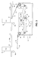
- FIG. 2 illustrates a side view of a dynamic registration device, that can be used in the mailing system of Fig. 1, in a first position;
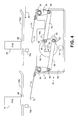
- FIG. 3 illustrates the dynamic registration device in a second position
- FIG. 4 illustrates the dynamic registration device in a third position.
- Fig. 1 in block diagram form portions of a mailing system 10 that includes a dynamic registration device according to embodiments of the invention.
- Mailing system 10 includes a main controller 12 that controls one or more operations of the mailing system 10.
- Main controller 12 may be implemented as hardware, firmware, as a general or special purpose processor that executes commands in response to software, or any combination thereof.
- a transport 14 is utilized to move articles, such as, for example, mail pieces, including envelopes, flats, postcards, and the like, through the mailing system 10.
- Transport 14 can be implemented in any conventional manner, such as, for example, a combination of rollers and belts as is well known.
- One or more sensors 16, located along the transport 14, provide the main controller 12 with status signals as to the location of an article along the transport 14.
- Sensors 16 can be implemented as optical sensors that are triggered by an article passing through a beam.
- the Mailing system 10 is provided with two print modules.
- the first print module includes a print head controller 18, coupled to the main controller 12, that drives a first print head, Print Head 1 (PH1), 20.
- the second print module is similar to the first and includes a print head controller 22, coupled to the main controller 12, that drives a second print head, Print Head 2 (PH2), 24.
- PH1 20 and PH2 24 are located in series along the transport 14, with PH1 20 being upstream of PH2 24.
- the print heads 20, 24 utilize digital printing technology. Accordingly, as transport 14 moves the articles past the print heads 20, 24, the articles are top registered to maintain the necessary gap between the nozzles of the print heads 20, 24 and the printing surface.
- Mailing system 10 is further provided with an actuator 30 that dynamically positions the articles in a top registration position based on which of the print heads 20, 24 is activated, i.e., actually printing, according to an embodiment of the present invention. Additionally, in other embodiments, the top registration positioning can be based on the actual print cycle timing.
- FIG. 2 there is illustrated a more detailed view of portions of the mailing system 10, and more specifically a dynamic registration device according to an embodiment of the invention.
- an article upon which information will be imprinted is transported (by transport 14, not shown in Figs. 2-4) in the direction of arrow 40 past the print heads PH1 20 and PH2 24.
- a registration plate which may comprise one or more portions such as 42a, 42b as illustrated, is utilized to top register the articles such that a small predetermined gap is maintained between the exit plane of the nozzles of the print heads 20, 24 and the surface of the article.
- the print heads 20, 24 can print on the article through a respective slot 44, 46 in the registration plates 42a, 42b as the article passes.
- Slots 44, 46 can extend from the beginning of the print heads 20, 24 through the downstream ends of the registration plate 42a, 42b, respectively.
- Sensors such as, for example, sensors 16a and 16b, which can be located at any point from slightly upstream to slightly downstream of the print heads 20, 24, provide signals to the main controller 12 (Fig. 1) to indicate the position of articles within the mailing system 10.
- Actuator 30 includes a pair of moveable skis 50, 70 that are utilized to apply pressure to the underside of an article such that it is top registered against a registration plate 42a, 42b.
- Ski 50 includes a contact portion 52 that will contact the underside of an article when the ski 50 is in the appropriate position, as described below, thereby top registering the article when being imprinted upon by print head PH2 24.
- Ski 50 is secured to a linking arm 54 that rotates about a fixed axis 56, which can be secured to a support bracket 96.
- Linking arm 54 is coupled to a linking arm 58 such that the linking arms 54, 58 can rotate with respect to each other about axis 60.
- the linking arm 58 is secured to a mounting bracket 88 such that it can rotate with respect to the mounting bracket 88 about an axis 62.
- the mounting bracket 88 includes a tab 90.
- Mounting bracket 88 is secured to the shaft 92 of a motor 94 such that when the motor 94 is energized and rotates the shaft 92, the mounting bracket 88 can also rotate until the tab 90 contacts one of the stops 100, 102 (depending upon which direction the shaft 92 is rotating) mounted to the support bracket 96.
- the motor 94 can also be mounted to the support bracket 96.
- Ski 70 includes a contact portion 72 that will contact the underside of an article when the ski 70 is in the appropriate position, as described below, thereby top registering the article when being imprinted upon by print head PH1 20.
- Ski 70 is secured to a linking arm 74 that rotates about a fixed axis 76, which can be secured to the support bracket 96.
- Linking arm 74 is coupled to a linking arm 78 such that the linking arms 74, 78 can rotate with respect to each other about axis 80.
- the linking arm 78 is secured to the mounting bracket 90 such that it can rotate with respect to the mounting bracket 90 about an axis 82.
- the operation of the dynamic registration device is as follows.
- the position of the skis 50, 70 is controlled by selectively energizing the motor 94.
- one of the print heads 20, 24 will be designated as the active print head, i.e., the print head that will be printing, and the other will be designated as the inactive print head.
- the print head PH2 24 is designated as the active print head. It is therefore necessary to top register the articles as they are passing beneath the print head PH2 24 to ensure proper printing thereon.
- the main controller 12 will provide a signal to the actuator 30 to place the ski 50 into a registration position as illustrated in Fig. 2.
- the registration position is defined as the position in which a contact point of a ski contacts the registration plate or is within a very small distance from the registration plate, such as, for example, one or two millimeters.
- the contact point 52 of ski 50 is in contact with or very close to the registration plate 42b.
- the positioning of the ski 50 is performed by energizing the motor 94 to rotate the shaft 92 into a position in which the ski 50 is in the registration position. As illustrated in Fig. 2, shaft 92 can be rotated in a clockwise direction until the tab 90 of the mounting bracket 88 contacts the stop 102.
- Skis 50, 70 are preferably formed of a rigid yet flexible material, such as, for example, sheet metal, thereby providing a biasing force but still capable of being flexed.
- ski 50 provides a biasing force against the bottom of the registration plate 42b for articles passing between the contact point 52 and the registration plate 42b. If a thicker article is being processed by the mailing system 10, the ski 50 can flex such that the thicker article can pass between the contact portion 52 and the registration plate 42b while still being biased against the bottom of the registration plate 42b.
- the motor 94 can allow for some rotational movement due to the force applied by the article on the ski 50, thereby allowing the very thick articles to pass between the contact point 52 and the registration plate 42b.
- the ski 70 when ski 50 is moved into the registration position, the ski 70 is preferably concurrently moved into a non-registration position, i.e., a position in which the contact portion 72 of the ski 70 is not near the registration plate 42a.
- a non-registration position i.e., a position in which the contact portion 72 of the ski 70 is not near the registration plate 42a.
- print head PH1 20 will be designated as the active print head and print head PH2 24 will be designated as the inactive print head.
- print head PH2 24 requiring scheduled maintenance, e.g., wiping, purging, etc. It is therefore necessary to top register the articles as they are passing beneath the print head PH1 20 to ensure proper printing thereon.
- the main controller 12 will provide a signal to the actuator 30 to place the ski 70 into a registration position as illustrated in Fig. 3. To move the ski 70 from the non-registration position as illustrated in Fig. 2 to the registration position as illustrated in Fig.
- the motor 94 is energized to rotate the shaft 92 in a counter-clockwise direction until the tab 90 of the mounting bracket 88 contacts the stop 100.
- the stops 100, 102 can be positioned between 50 and 60 degrees apart, such that the shaft 92 can be rotated between 50 and 60 degrees.
- the rotation of the shaft 92 from the position illustrated in Fig. 2 to the position illustrated in Fig. 3 is approximately 56 degrees. Rotation of the shaft 92 in a counter-clockwise direction will cause the linking arm 78 to pull the linking arm 74 such that the linking arm 74 rotates about the axis 76 in a clockwise direction, thereby causing the ski 70 to lift upward into the registration position.
- the contact portion 72 of the ski 70 contacts or is in very close proximity to the bottom of the registration plate 42a such that an article passing between the bottom of the registration plate 42a and the contact portion 72 of the ski 70 will be biased against the bottom of the registration plate 42a by the ski 70.
- print head PH2 24 is designated as the active print head and print head PH1 20 is designated as the inactive print head
- the main controller 12 will send a signal to actuator 30 to place the ski 50 into the registration position as previously described above.
- the biasing force to top register articles being passed under the print heads 20, 24 is applied only under the selected one of the print heads that is actually printing.
- the amount of paper dust generated can be reduced as compared with the amount generated if the articles were top registered under both print heads.
- the first print head PH1 20 is the active print head, i.e., performing the print operation, there is no risk that the ink printed on the articles by print head PH1 20 will be smeared by contact with the registration plate 42b since the articles are not top registered as they pass under the print head PH2 24.
- the actuator 30 can additionally place both skis 50, 70 in an intermediate position between the registered and non-registered positions. In the intermediate position, neither ski 50 nor ski 70 will apply a biasing force to top register an article. This position is illustrated in Fig. 4, wherein the tab 90 of the mounting bracket 88 is located approximately halfway between the stops 100, 102. This intermediate position can be utilized between printing of different articles by the same print head to further reduce the generation of paper dust and prevent the trailing edge of the article from contacting the print head as it passes. For example, suppose print head PH2 24 is the designated active print head. The main controller 12 will have sent a signal to actuator 30 to move the ski 50 into the registration position as illustrated in Fig. 2.
- the print head controller 22 will provide a signal to the print head PH2 24 to cause the print head PH2 24 to print. Once the print cycle has been completed, it is no longer necessary to maintain the article in a top registered position. Upon completion of the print cycle for the article, the print head controller 22 sends a signal to the main controller 12, which in response sends a signal to the actuator 30 to position the ski 50 in the intermediate position. The motor 94 will be energized to rotate the shaft 92 in a counter-clockwise direction a predetermined distance, thereby lowering the ski 50 from the registration position to the intermediate position.
- the location of an indicium evidencing payment of postage must be located in a specified location, e.g., the upper right hand corner of the face of the mail piece.
- the indicium occupies only a small portion of the length of the envelope.
- the main controller 12 When the trailing edge of the article is detected by sensor 16b, the main controller 12 will send a signal to the actuator 30 to place the ski 50 back into the registration position, as described above and illustrated in Fig. 2, such that the next article to arrive will be top registered. Thus, the trailing edge of the article will have passed by the print head PH2 24 before the ski 50 is placed back into the registration position. Since the gap between articles may be very small, especially in high speed systems with large throughputs, the use of the intermediate position, in which the distance the skis 50, 70 must travel is minimized, assures that the ski 50 will be back in the top registration position before the next article arrives for printing.
- the operation of the actuator 30 when the print head PH1 20 is the active printer is similar.
- the print head controller 18 sends a signal to the main controller 12, which in response sends a signal to the actuator 30 to position the ski 70 in the intermediate position.
- the motor 94 will be energized to rotate the shaft 92 in a clockwise direction a predetermined distance, thereby lowering the ski 70 from the registration position to the intermediate position.
- the main controller 12 will send a signal to the actuator 30 to place the ski 70 back into the registration position, as described above and illustrated in Fig. 3, such that the next article to arrive will be top registered.
- the actuator 30 need only be provided with a single ski that can be moved between the registration position and the intermediate position, thereby reducing the amount of paper dust generated by the mailing system and the risk of the trailing edge of the article contacting the print head as it passes beneath.
- the position of the shaft 92 can be controlled utilizing any conventional means, including rotary solenoids, torque actuators and the like.
- the skis 50, 70 can also be formed of any type of material that is rigid enough to provide a biasing force, yet flexible enough to accommodate articles of various thickness.
Abstract
Description
- The invention disclosed herein relates generally to mailing systems, and more particularly to a dynamic registration device for a mailing system.
- Mailing systems, such as, for example, a mailing machine, inserter, and the like, often include different modules that automate the processes of producing mail pieces. A typical mailing system includes a variety of different modules or subsystems each of which performs a different task on the mail piece. The mail piece is conveyed downstream utilizing a transport mechanism, such as rollers or a belt, to each of the modules. In a mailing machine, such modules could include, for example, a singulating module, i.e., separating a stack of mail pieces such that the mail pieces are conveyed one at a time along the transport path, a moistening/sealing module, i.e., wetting and closing the glued flap of an envelope, a weighing module, and a metering/printing module, i.e., applying evidence of postage to the mail piece. In an inserter, such modules could include one or more feeders and collators, an envelope stuffing module, a moistening/sealing module, i.e., wetting and closing the glued flap of an envelope, a weighing module, and a metering/printing module, i.e., applying evidence of postage to the mail piece. The exact configuration of the mailing system is, of course, particular to the needs of the user.
- Some high speed mailing systems may utilize more than one printing module in series. For example, some high speed inserter systems can process up to 22,000 mail pieces per hour. The printing modules in such high speed systems require maintenance at periodic intervals to clean the print heads, replace ink cartridges, etc. Such maintenance requires the print module to be inactive, i.e., not perform any print operations, for a certain period of time. In high speed systems, it would be required to stop the system completely to allow this maintenance period to occur. Because of the high volume of mail pieces processed, even very short periods of down-time for maintenance can significantly impact the throughput of the system. For example, halting a system that typically process 22,000 pieces per hour for only two minutes will reduce the throughput by 733 pieces per hour. If the maintenance is required to be performed at least once per hour, in an eight hour day the throughput of the machine will be decreased by almost 6,000 pieces. To minimize any down-time of the system, it is known to place two print heads or modules (collectively referred to hereinafter as print or printing modules) in series along the transport path, where only one of the printing modules is activated at a time. Thus, when one of the printing modules requires maintenance operations, it can be inactivated and the other printing module activated to print on the mail pieces. For example, if the first printing module requires maintenance, the first printing module is inactivated and the second printing module is activated. Mail pieces will pass through the first printing module, without being imprinted upon, to the second printing module, where printing will occur. When the second printing module requires maintenance, the second printing module is inactivated and the first printing module is activated. Mail pieces will be imprinted upon by the first printing module and will pass through the second printing module without being imprinted with any information.
- Modern mailing systems utilize digital printing techniques for producing images on a mail piece. Conventional digital printing techniques include bubble jet and ink jet, each of which produces an image in a dot matrix pattern. With digital printing, individual print head elements (such as resistors or piezoelectric elements) are selectively electronically stimulated to expel drops of ink from a reservoir onto a substrate, e.g., a mail piece. In either case, by controlling the timing of energizing of the individual print head elements in conjunction with the relative movement between the print head and the mail piece, a dot matrix pattern is produced in the visual form of the desired image. In the case of mailing systems, the image may be, for example, an indicium that evidences payment of postage.
- Digital printing technology has significant advantages when used in a mail handling apparatus as compared to older technology that utilized either a flat platen or a rotary drum to imprint information, such as, for example, address information or an indicium, on mail pieces. For example, if some variable image data needs to be changed, it can easily be done through the installation of new or upgraded software versus having to replace the entire printing module, since the flat platen and drum are typically not separately removable. Moreover, greater printing speeds can be obtained as compared to conventional mechanical printing systems. However, the use of a digital print head in a mailing system presents other issues that must be taken into consideration. For example, for the ink jet nozzles of an ink jet printer to properly deposit ink on the surface of the receiving medium, it is critical that a small predetermined gap be maintained between the exit plane of the nozzles and the surface of the receiving medium, typically in the order of one sixteenth to one thirty-second of an inch. This gap is necessary to achieve acceptable image quality, since too small a gap causes scuffing of the print head and to large a gap results in inaccurate dot placement, with either situation resulting in a deteriorated print image. Thus, in the mail handling environment, it becomes necessary to maintain this critical gap between the exit plane of the ink jet nozzles and the upper surface of the mail pieces being conveyed through the mailing machine.
- To accomplish this, the mail pieces, such as, for example, envelopes, postcards, flats, and the like, must be conveyed with the front panels on which the information is printed lying in a fixed registration plane, which is disposed beneath the exit plane of the nozzles a distance equal to the aforementioned gap. This arrangement is referred to hereinafter as top registration. To accomplish this top registration, a biasing force is applied to the back panel of the mail piece such that the front panel maintains contact with a registration plate. An opening is provided in the registration plate, above which the print head is located such that the print head can print on the mail piece as it passes the opening in the registration plate.
- There are problems, however, with the conventional top registration transports in mailing systems. For example, friction between the mail piece and registration plate results in the generation of paper dust. The presence of dust within a mailing system can cause several problems, including, for example, clogging the nozzles of the print head. Dust accumulation can also interfere with maintenance operations performed by the mailing system on the print head, including, for example, wiping and capping of the print head. Another problem with top registration is the potential for the trailing edge of a mail piece to hit the print head as it is transported past the print head, thereby potentially damaging the print head. Systems with multiple printing modules present additional problems with conventional top registration. For example, even though one of the printing modules is inactivated, i.e., not printing, the mail pieces still must pass through both print modules. Although printing is not occurring in one of the modules, the mail pieces are still transported through the inactive printing module in a top registration position. Thus, the front panel of the mail piece is still in contact with registration plate, resulting in the generation of additional paper dust. Having to pass each mail piece through two printing modules will double the amount of paper dust generated, thereby increasing the risk of associated problems. Another problem with multiple printing modules is the smearing of ink printed on a mail piece by the first print module as the mail piece passes through the second print module. There is insufficient time for the ink deposited on a mail piece by the first print module to dry before the mail piece reaches the second print module. As such, the wet ink can smear when the mail piece makes contact with the registration plate of the second print module. The smearing of the ink can result in unreadable information. This is especially critical in the case of an indicium that includes a bar code that must be scanned for verification purposes. If the bar code is unreadable, the indicium cannot be verified and the mail piece may not be delivered.
- Thus, there exists a need for a top registration device for a mailing system that reduces the problems of dust generation, ink smearing, and contact of the print head by the trail end of a mail piece.
- The present invention alleviates the problems associated with the prior art and provides a top registration device for a mailing system that reduces the problems of dust generation, ink smearing, and contact of the print head by the trailing edge of a mail piece.
- In accordance with an embodiment of the present invention, the biasing force normally applied to the back panel of the mail piece, such that the front panel maintains contact with the top registration plate, is controlled by an actuator such that the force can be selectively applied and removed. In some embodiments, the biasing force can be applied only when the print head is actually printing and removed once printing has been completed. Since the biasing force will not be present along the entire length of the mail piece, the amount of paper dust generated can be reduced, and the risk of the trailing edge of the mail piece contacting the print head is significantly reduced. In other embodiments utilizing multiple printing modules, when one of the printing modules is inactivated, the biasing force can be removed, and the mail pieces pass through the inactive printing module without being registered against the top registration plate. Thus, if a first printing module imprints upon the mail pieces, the ink will not be smeared as the mail pieces pass through the inactive second printing module.
- In an embodiment of the invention, a rotary actuator is provided that is controlled to selectively apply the biasing force to register a mail piece with the top registration plate. In embodiments with multiple printing modules, the actuator can selectively apply the biasing force for one of the printing modules. The biasing force can be removed when printing has been completed, thereby reducing the generation of paper dust and the risk of the print head being contacted by the trailing edge of a mail piece.
- Therefore, it should now be apparent that the invention substantially achieves all the above aspects and advantages. Additional aspects and advantages of the invention will be set forth in the description that follows, and in part will be obvious from the description, or may be learned by practice of the invention. Moreover, the aspects and advantages of the invention may be realized and obtained by means of the instrumentalities and combinations particularly pointed out in the appended claims.
- The accompanying drawings illustrate presently preferred embodiments of the invention, and together with the general description given above and the detailed description given below, by way of example serve to explain the invention in more detail. As shown throughout the drawings, like reference numerals designate like or corresponding parts.
- FIG. 1 illustrates in block diagram form portions of a mailing system according to an embodiment of the present invention;
- FIG. 2 illustrates a side view of a dynamic registration device, that can be used in the mailing system of Fig. 1, in a first position;
- FIG. 3 illustrates the dynamic registration device in a second position; and
- FIG. 4 illustrates the dynamic registration device in a third position.
- In describing the present invention, reference is made to the drawings, wherein there is seen in Fig. 1 in block diagram form portions of a
mailing system 10 that includes a dynamic registration device according to embodiments of the invention.Mailing system 10 includes amain controller 12 that controls one or more operations of themailing system 10.Main controller 12 may be implemented as hardware, firmware, as a general or special purpose processor that executes commands in response to software, or any combination thereof. Atransport 14 is utilized to move articles, such as, for example, mail pieces, including envelopes, flats, postcards, and the like, through themailing system 10.Transport 14 can be implemented in any conventional manner, such as, for example, a combination of rollers and belts as is well known. One ormore sensors 16, located along thetransport 14, provide themain controller 12 with status signals as to the location of an article along thetransport 14.Sensors 16 can be implemented as optical sensors that are triggered by an article passing through a beam. -
Mailing system 10 is provided with two print modules. The first print module includes aprint head controller 18, coupled to themain controller 12, that drives a first print head, Print Head 1 (PH1), 20. The second print module is similar to the first and includes aprint head controller 22, coupled to themain controller 12, that drives a second print head, Print Head 2 (PH2), 24.PH1 20 andPH2 24 are located in series along thetransport 14, withPH1 20 being upstream ofPH2 24. The print heads 20, 24 utilize digital printing technology. Accordingly, astransport 14 moves the articles past the print heads 20, 24, the articles are top registered to maintain the necessary gap between the nozzles of the print heads 20, 24 and the printing surface.Mailing system 10 is further provided with anactuator 30 that dynamically positions the articles in a top registration position based on which of the print heads 20, 24 is activated, i.e., actually printing, according to an embodiment of the present invention. Additionally, in other embodiments, the top registration positioning can be based on the actual print cycle timing. - Referring now to Figs. 2-4, there is illustrated a more detailed view of portions of the
mailing system 10, and more specifically a dynamic registration device according to an embodiment of the invention. As illustrated in Fig. 2, an article (not shown) upon which information will be imprinted is transported (bytransport 14, not shown in Figs. 2-4) in the direction ofarrow 40 past the print headsPH1 20 andPH2 24. A registration plate, which may comprise one or more portions such as 42a, 42b as illustrated, is utilized to top register the articles such that a small predetermined gap is maintained between the exit plane of the nozzles of the print heads 20, 24 and the surface of the article. The print heads 20, 24 can print on the article through arespective slot registration plates Slots registration plate sensors mailing system 10. - The articles are selectively registered against the one of the
registration plates actuator 30.Actuator 30 includes a pair ofmoveable skis registration plate Ski 50 includes acontact portion 52 that will contact the underside of an article when theski 50 is in the appropriate position, as described below, thereby top registering the article when being imprinted upon byprint head PH2 24.Ski 50 is secured to alinking arm 54 that rotates about a fixedaxis 56, which can be secured to asupport bracket 96. Linkingarm 54 is coupled to alinking arm 58 such that the linkingarms axis 60. The linkingarm 58 is secured to a mountingbracket 88 such that it can rotate with respect to the mountingbracket 88 about anaxis 62. The mountingbracket 88 includes atab 90. Mountingbracket 88 is secured to theshaft 92 of amotor 94 such that when themotor 94 is energized and rotates theshaft 92, the mountingbracket 88 can also rotate until thetab 90 contacts one of thestops 100, 102 (depending upon which direction theshaft 92 is rotating) mounted to thesupport bracket 96. Themotor 94 can also be mounted to thesupport bracket 96. -
Ski 70 includes acontact portion 72 that will contact the underside of an article when theski 70 is in the appropriate position, as described below, thereby top registering the article when being imprinted upon byprint head PH1 20.Ski 70 is secured to alinking arm 74 that rotates about a fixedaxis 76, which can be secured to thesupport bracket 96. Linkingarm 74 is coupled to alinking arm 78 such that the linkingarms axis 80. The linkingarm 78 is secured to the mountingbracket 90 such that it can rotate with respect to the mountingbracket 90 about anaxis 82. - The operation of the dynamic registration device according to an embodiment of the invention is as follows. The position of the
skis motor 94. When themailing system 10 is powered for operation, one of the print heads 20, 24 will be designated as the active print head, i.e., the print head that will be printing, and the other will be designated as the inactive print head. Suppose, for example, theprint head PH2 24 is designated as the active print head. It is therefore necessary to top register the articles as they are passing beneath theprint head PH2 24 to ensure proper printing thereon. Themain controller 12 will provide a signal to theactuator 30 to place theski 50 into a registration position as illustrated in Fig. 2. The registration position is defined as the position in which a contact point of a ski contacts the registration plate or is within a very small distance from the registration plate, such as, for example, one or two millimeters. Thus, whenski 50 is in the registration position, thecontact point 52 ofski 50 is in contact with or very close to theregistration plate 42b. The positioning of theski 50 is performed by energizing themotor 94 to rotate theshaft 92 into a position in which theski 50 is in the registration position. As illustrated in Fig. 2,shaft 92 can be rotated in a clockwise direction until thetab 90 of the mountingbracket 88 contacts thestop 102. Rotation of theshaft 92 in the clockwise direction will cause the linkingarm 58 to push thelinking arm 54 such that the linkingarm 54 rotates about theaxis 56 in a clockwise direction, thereby causing theski 50 to lift upward into the registration position. Thus, thecontact portion 52 of theski 50 contacts or is in very close proximity to the bottom of theregistration plate 42b such that an article passing between the bottom of theregistration plate 42b and thecontact portion 52 of theski 50 will be biased against the bottom of theregistration plate 42b by theski 50.Skis ski 50 provides a biasing force against the bottom of theregistration plate 42b for articles passing between thecontact point 52 and theregistration plate 42b. If a thicker article is being processed by themailing system 10, theski 50 can flex such that the thicker article can pass between thecontact portion 52 and theregistration plate 42b while still being biased against the bottom of theregistration plate 42b. Optionally, if theski 50 is not flexible enough to accommodate very thick articles, themotor 94 can allow for some rotational movement due to the force applied by the article on theski 50, thereby allowing the very thick articles to pass between thecontact point 52 and theregistration plate 42b. - As illustrated in Fig. 2, when
ski 50 is moved into the registration position, theski 70 is preferably concurrently moved into a non-registration position, i.e., a position in which thecontact portion 72 of theski 70 is not near theregistration plate 42a. Thus, as articles of any thickness are transported past theprint head PH1 20, there is no biasing force applied to the article, i.e., the articles are not top registered. This provides several advantages. For example, the amount of paper dust generated by friction of the article being top registered is reduced, as the article is only top registered when actually being printed upon instead of when passing under both the active and inactive print head. - Now suppose, for example, that
print head PH1 20 will be designated as the active print head andprint head PH2 24 will be designated as the inactive print head. This could be caused, for example, byprint head PH2 24 requiring scheduled maintenance, e.g., wiping, purging, etc. It is therefore necessary to top register the articles as they are passing beneath theprint head PH1 20 to ensure proper printing thereon. Themain controller 12 will provide a signal to theactuator 30 to place theski 70 into a registration position as illustrated in Fig. 3. To move theski 70 from the non-registration position as illustrated in Fig. 2 to the registration position as illustrated in Fig. 3, themotor 94 is energized to rotate theshaft 92 in a counter-clockwise direction until thetab 90 of the mountingbracket 88 contacts thestop 100. For example, thestops shaft 92 can be rotated between 50 and 60 degrees. Preferably, the rotation of theshaft 92 from the position illustrated in Fig. 2 to the position illustrated in Fig. 3 is approximately 56 degrees. Rotation of theshaft 92 in a counter-clockwise direction will cause the linkingarm 78 to pull the linkingarm 74 such that the linkingarm 74 rotates about theaxis 76 in a clockwise direction, thereby causing theski 70 to lift upward into the registration position. Thus, thecontact portion 72 of theski 70 contacts or is in very close proximity to the bottom of theregistration plate 42a such that an article passing between the bottom of theregistration plate 42a and thecontact portion 72 of theski 70 will be biased against the bottom of theregistration plate 42a by theski 70. - Movement of the
ski 70 into the registration position will also concurrently cause theski 50 to be moved into the non-registration position. The rotation of theshaft 92 in the counter-clockwise direction will cause the linkingarm 58 to pull the linkingarm 54 such that the linkingarm 54 rotates about theaxis 56 in a counter-clockwise direction, thereby causing theski 50 to lower into the non-registration position. Thus, as articles of any thickness are transported by theprint head PH2 24, there is no biasing force applied to the article, i.e., the articles are not top registered. This provides several advantages. For example, there is no risk that the ink printed on the articles byprint head PH1 20 will be smeared due to contact with theregistration plate 42b as the article passes under theprint head PH2 24. Additionally, the amount of paper dust generated by friction of the article being top registered is reduced, as the article is only top registered when actually being printed upon instead of when passing under both the active and inactive print head. If the designation of the print heads again changes, i.e.,print head PH2 24 is designated as the active print head andprint head PH1 20 is designated as the inactive print head, themain controller 12 will send a signal toactuator 30 to place theski 50 into the registration position as previously described above. - As illustrated in Figs. 2 and 3, the biasing force to top register articles being passed under the print heads 20, 24 is applied only under the selected one of the print heads that is actually printing. Thus, the amount of paper dust generated can be reduced as compared with the amount generated if the articles were top registered under both print heads. In addition, if the first
print head PH1 20 is the active print head, i.e., performing the print operation, there is no risk that the ink printed on the articles byprint head PH1 20 will be smeared by contact with theregistration plate 42b since the articles are not top registered as they pass under theprint head PH2 24. - In other embodiments, the
actuator 30 can additionally place bothskis ski 50 norski 70 will apply a biasing force to top register an article. This position is illustrated in Fig. 4, wherein thetab 90 of the mountingbracket 88 is located approximately halfway between thestops print head PH2 24 is the designated active print head. Themain controller 12 will have sent a signal toactuator 30 to move theski 50 into the registration position as illustrated in Fig. 2. As the article passes under theprint head PH2 24, theprint head controller 22 will provide a signal to theprint head PH2 24 to cause theprint head PH2 24 to print. Once the print cycle has been completed, it is no longer necessary to maintain the article in a top registered position. Upon completion of the print cycle for the article, theprint head controller 22 sends a signal to themain controller 12, which in response sends a signal to theactuator 30 to position theski 50 in the intermediate position. Themotor 94 will be energized to rotate theshaft 92 in a counter-clockwise direction a predetermined distance, thereby lowering theski 50 from the registration position to the intermediate position. Thus, as the remaining portion of the article passes under theprint head PH2 24, it will not be top registered, thereby reducing the generation of paper dust and the risk of the trailing edge of the article contacting theprint head PH2 24 through theslot 46. For example, if the article is a mail piece, the location of an indicium evidencing payment of postage must be located in a specified location, e.g., the upper right hand corner of the face of the mail piece. For a standard size envelope, the indicium occupies only a small portion of the length of the envelope. Thus, when the indicium is finished being printed, the biasing force on the envelope can be removed, thereby allowing the remaining length of the envelope to pass under theprint head PH2 24 without being top registered. - When the trailing edge of the article is detected by
sensor 16b, themain controller 12 will send a signal to theactuator 30 to place theski 50 back into the registration position, as described above and illustrated in Fig. 2, such that the next article to arrive will be top registered. Thus, the trailing edge of the article will have passed by theprint head PH2 24 before theski 50 is placed back into the registration position. Since the gap between articles may be very small, especially in high speed systems with large throughputs, the use of the intermediate position, in which the distance theskis ski 50 will be back in the top registration position before the next article arrives for printing. - The operation of the
actuator 30 when theprint head PH1 20 is the active printer is similar. Upon completion of the print cycle for the article, theprint head controller 18 sends a signal to themain controller 12, which in response sends a signal to theactuator 30 to position theski 70 in the intermediate position. Themotor 94 will be energized to rotate theshaft 92 in a clockwise direction a predetermined distance, thereby lowering theski 70 from the registration position to the intermediate position. Thus, as the remaining portion of the article passes under theprint head PH1 20, it will not be top registered, thereby reducing the generation of paper dust and the risk of the trailing edge of the article contacting theprint head PH1 20 through theslot 44. When the trailing edge of the article is detected bysensor 16a, themain controller 12 will send a signal to theactuator 30 to place theski 70 back into the registration position, as described above and illustrated in Fig. 3, such that the next article to arrive will be top registered. - It should be understood that while the above description was with respect to a
mailing system 10 having multiple print modules, other embodiments can also be utilized with only a single print module. For example, theactuator 30 need only be provided with a single ski that can be moved between the registration position and the intermediate position, thereby reducing the amount of paper dust generated by the mailing system and the risk of the trailing edge of the article contacting the print head as it passes beneath. - Those skilled in the art will also recognize that various modifications to the above embodiments can be made. For example, the position of the
shaft 92 can be controlled utilizing any conventional means, including rotary solenoids, torque actuators and the like. Theskis
Claims (11)
- A mailing system for processing mail pieces, said processing including printing on an upper surface of a mail piece passing through the mailing system, the mailing system comprising:a first printing device including a first print head having a plurality of nozzles disposed in a predetermined plane to deposit ink on the upper surface of a mail piece;a registration plate arranged to register the upper surface of a mail piece at a predetermined distance beneath the plurality of nozzles of the first print head;a transport device to transport a mail piece under the plurality of nozzles;a first biasing means to apply a biasing force to a lower surface of the mail piece to register the upper surface of the mail piece against the registration plate beneath the first printing device; andan actuator device coupled to the first biasing means, the actuator device controlling a position of the first biasing means to selectively apply the biasing force when the first printing device is printing on the mail piece and to remove the biasing force when the printing has been completed by the first printing device.
- The mailing system of claim 1, wherein the actuator device includes a motor having a shaft, the shaft being coupled to the first biasing means by a linking mechanism,
wherein rotation of the shaft by the motor in a first direction causes the first biasing means to move into a first position to apply the biasing force, and rotation of the shaft by the motor in a second direction opposite the first direction causes the first biasing means to move into a second position to remove the biasing force. - The mailing system of claim 1, further comprising:wherein only one of the first and second printing device is active at a time, and the actuator device controls a position of the first and second biasing means to selectively apply the biasing force only beneath the active print device when the active print device is printing.a second printing device including a second print head having a plurality of nozzles disposed in a predetermined plane to deposit ink on the upper surface of a mail piece, the registration plate additionally arranged to register the upper surface of a mail piece at a predetermined distance beneath the plurality of nozzles of the second print head: anda second biasing means to apply a biasing force to a lower surface of the mail piece to register the upper surface of the mail piece against the registration plate beneath the second printing device, the second biasing means being coupled to the actuator device,
- The mailing system of claim 3, wherein the first and second biasing means are skis.
- The mailing system of claim 1, further comprising:wherein the actuator device in response to the trailing edge being detected positions the first biasing means to apply the biasing force for a next mail piece.a sensor to detect when a trailing edge of the mail piece is passing the first printing device,
- In a mailing machine having a first and second print module, a method for registering a surface of a mail piece against a registration plate comprising:selecting one of the first print module and second print module as an active print module and the other as an inactive print module;moving a first ski to a first position, the first ski when in the first position applying a biasing force to the mail piece to register a top surface of the mail piece against the registration plate as the mail piece passes beneath the active print module; andmoving a second ski to a second position, the second ski when in the second position not applying the biasing force to the mail piece as the mail piece passes beneath the inactive print module such that the top surface of the mail piece is not registered against the registration plate.
- The method of claim 6, wherein moving a first ski and moving a second ski further comprise:wherein rotation of the shaft of the motor in the first direction causes the first ski to move into the first position to apply the biasing force and the second ski to move into the second position to not apply the biasing force.rotating a shaft of a motor in a first direction,
- The method of claim 7, further comprising:wherein rotation of the shaft of the motor in the second direction causes the first ski to move into the second position to not apply the biasing force and the second ski to move into the first position to apply the biasing force.changing the active module to the inactive module and the inactive module to the active module; androtating the shaft of the motor in a second direction opposite the first direction,
- The method of claim 6, wherein moving the first ski further comprises:moving the first ski to the first position only when the active print module is printing on the mail piece; andmoving the first ski and the second ski to a third position when the active print module has completed printing on the mail piece, the first and second skis when in the third position not applying a biasing force to the mail piece.
- The method of claim 9, wherein the third position is located between the first and second positions.
- The method of claim 9, further comprising:detecting a trailing edge of the mail piece; andmoving the first ski back to the first position in response to detection of the trailing edge of the mail piece.
Applications Claiming Priority (2)
| Application Number | Priority Date | Filing Date | Title |
|---|---|---|---|
| US742305 | 2003-12-18 | ||
| US10/742,305 US6966711B2 (en) | 2003-12-18 | 2003-12-18 | Dynamic registration device for mailing system |
Publications (3)
| Publication Number | Publication Date |
|---|---|
| EP1544801A2 true EP1544801A2 (en) | 2005-06-22 |
| EP1544801A3 EP1544801A3 (en) | 2006-09-20 |
| EP1544801B1 EP1544801B1 (en) | 2008-09-10 |
Family
ID=34523246
Family Applications (1)
| Application Number | Title | Priority Date | Filing Date |
|---|---|---|---|
| EP04030025A Expired - Fee Related EP1544801B1 (en) | 2003-12-18 | 2004-12-17 | Dynamic registration device for mailing system |
Country Status (3)
| Country | Link |
|---|---|
| US (2) | US6966711B2 (en) |
| EP (1) | EP1544801B1 (en) |
| DE (1) | DE602004016449D1 (en) |
Cited By (1)
| Publication number | Priority date | Publication date | Assignee | Title |
|---|---|---|---|---|
| EP2043053A1 (en) * | 2007-09-28 | 2009-04-01 | Böwe Bell + Howell GmbH | Letter processing device with printer |
Families Citing this family (5)
| Publication number | Priority date | Publication date | Assignee | Title |
|---|---|---|---|---|
| US7810803B2 (en) * | 2007-05-24 | 2010-10-12 | Hewlett-Packard Development Company, L.P. | Sheet constraint |
| US8162468B2 (en) * | 2008-12-15 | 2012-04-24 | Pitney Bowes Inc. | System and method for registering color ink jet printing in a mailing machine |
| US8353510B2 (en) * | 2010-05-17 | 2013-01-15 | Lindsay Brett A | Variable media feed system and printhead apparatus |
| DE102012103712B4 (en) * | 2012-04-27 | 2015-10-15 | Böwe Systec Gmbh | Apparatus and method for serial printing of print media |
| TWI615267B (en) * | 2017-09-20 | 2018-02-21 | 東友科技股份有限公司 | Dual printhead assembly and 3d printing apparatus using the same |
Citations (3)
| Publication number | Priority date | Publication date | Assignee | Title |
|---|---|---|---|---|
| JPS63173655A (en) * | 1987-01-13 | 1988-07-18 | Canon Inc | Thermal recorder |
| US4821049A (en) * | 1987-12-02 | 1989-04-11 | Pitney Bowes Inc. | Substrate transport apparatus, especially for mail handling |
| EP0891870A2 (en) * | 1997-07-18 | 1999-01-20 | Star Micronics Co., Ltd. | Printer |
Family Cites Families (15)
| Publication number | Priority date | Publication date | Assignee | Title |
|---|---|---|---|---|
| US533980A (en) * | 1895-02-12 | Paper weight and clip | ||
| US4879566A (en) | 1987-01-13 | 1989-11-07 | Canon Kabushiki Kaisha | Thermal recording apparatus |
| US5339280A (en) * | 1992-09-24 | 1994-08-16 | Pitney Bowes Inc. | Platen roller and pressure roller assemblies for thermal postage meter |
| US5325114A (en) * | 1992-09-24 | 1994-06-28 | Pitney Bowes Inc. | Thermal printing postage meter system |
| US5611629A (en) * | 1993-03-30 | 1997-03-18 | Paranjpe; Suresh C. | Multiple print head nonimpact printing apparatus |
| US5465662A (en) * | 1994-11-04 | 1995-11-14 | Pitney Bowes Inc. | Envelope positioning assembly |
| GB9601898D0 (en) * | 1996-01-31 | 1996-04-03 | Neopost Ltd | Printing apparatus |
| US5683187A (en) * | 1996-06-18 | 1997-11-04 | Scitex Digital Printing, Inc. | Digital color press platen assembly with pivoting platen frame |
| FR2758762B1 (en) * | 1997-01-24 | 1999-04-16 | Neopost Ind | POSTAL PRINTHEAD WITH AN ALIGNMENT ADJUSTMENT DEVICE |
| US5806994A (en) * | 1997-10-15 | 1998-09-15 | Pitney Bowes Inc. | Mailing machine having ink jet printing and maintenance system |
| US6024429A (en) * | 1997-10-30 | 2000-02-15 | Pitney Bowes Inc. | Mailing machine including ink jet printing having ink availability checking |
| US6179419B1 (en) * | 1998-09-29 | 2001-01-30 | Hewlett-Packard | Belt driven media handling system with feedback control for improving media advance accuracy |
| FR2790997B1 (en) * | 1999-03-16 | 2001-06-01 | Secap | DEVICE FOR PRINTING A SIGN AND MACHINE FOR POSTAGE THE BEARING |
| DE10114530A1 (en) * | 2001-03-21 | 2002-10-02 | Francotyp Postalia Ag | Franking machine with clamping device for a mail piece |
| US6938894B2 (en) * | 2002-12-19 | 2005-09-06 | Pitney Bowes Inc. | Transport mechanism and method for a mailing machine |
-
2003
- 2003-12-18 US US10/742,305 patent/US6966711B2/en not_active Expired - Lifetime
-
2004
- 2004-12-17 EP EP04030025A patent/EP1544801B1/en not_active Expired - Fee Related
- 2004-12-17 DE DE602004016449T patent/DE602004016449D1/en active Active
-
2005
- 2005-07-14 US US11/181,558 patent/US7475979B2/en active Active
Patent Citations (3)
| Publication number | Priority date | Publication date | Assignee | Title |
|---|---|---|---|---|
| JPS63173655A (en) * | 1987-01-13 | 1988-07-18 | Canon Inc | Thermal recorder |
| US4821049A (en) * | 1987-12-02 | 1989-04-11 | Pitney Bowes Inc. | Substrate transport apparatus, especially for mail handling |
| EP0891870A2 (en) * | 1997-07-18 | 1999-01-20 | Star Micronics Co., Ltd. | Printer |
Non-Patent Citations (1)
| Title |
|---|
| PATENT ABSTRACTS OF JAPAN vol. 012, no. 442 (M-766), 21 November 1988 (1988-11-21) & JP 63 173655 A (CANON INC), 18 July 1988 (1988-07-18) * |
Cited By (1)
| Publication number | Priority date | Publication date | Assignee | Title |
|---|---|---|---|---|
| EP2043053A1 (en) * | 2007-09-28 | 2009-04-01 | Böwe Bell + Howell GmbH | Letter processing device with printer |
Also Published As
| Publication number | Publication date |
|---|---|
| US7475979B2 (en) | 2009-01-13 |
| US6966711B2 (en) | 2005-11-22 |
| US20050135859A1 (en) | 2005-06-23 |
| US20050251493A1 (en) | 2005-11-10 |
| EP1544801B1 (en) | 2008-09-10 |
| DE602004016449D1 (en) | 2008-10-23 |
| EP1544801A3 (en) | 2006-09-20 |
Similar Documents
| Publication | Publication Date | Title |
|---|---|---|
| US7475979B2 (en) | Dynamic registration device for mailing system | |
| EP0718799B1 (en) | Mailing machine utilizing ink jet printer | |
| US8186787B2 (en) | Method and apparatus for printing on variable thickness print media | |
| US6910766B2 (en) | Franking machine | |
| EP1901237B1 (en) | Method and system for high speed digital metering using low velocity print technology | |
| US7040616B2 (en) | Method and system for high speed digital metering using overlapping envelopes | |
| US5094554A (en) | Addressing machine | |
| US6182566B1 (en) | Printer device and method for printing on a print medium | |
| EP0480719A2 (en) | Addressing machine | |
| EP0647922A2 (en) | Apparatus for sensing mail piece surface contour | |
| US6988842B2 (en) | Method and apparatus for continuous high speed digital metering using multiple print heads | |
| EP1431925B1 (en) | Transport mechanism for a mailing machine and method to register a mail piece in a mailing machine | |
| EP1391849B1 (en) | Parallel processing high speed printing system for an inserting system | |
| US5623876A (en) | Apparatus and method for positioning a printing mechanism between stations in a mail handling apparatus | |
| US6893175B2 (en) | Method and system for high speed digital metering | |
| US5717165A (en) | Apparatus and method for positioning and isolating a printing mechanism in a mail handling machine | |
| US8576264B2 (en) | Registration device for mail processing system having wide print nozzle arrays | |
| US7059694B2 (en) | Method and system for securing printing process in mailing systems with multiple print heads | |
| US7494201B2 (en) | System and method for reducing printing errors by limiting the firing frequency of a print head | |
| EP1550560B1 (en) | Postage meter for printing near the top edge of an envelope | |
| EP1521218B1 (en) | Method and system for high speed digital metering |
Legal Events
| Date | Code | Title | Description |
|---|---|---|---|
| PUAI | Public reference made under article 153(3) epc to a published international application that has entered the european phase |
Free format text: ORIGINAL CODE: 0009012 |
|
| AK | Designated contracting states |
Kind code of ref document: A2 Designated state(s): AT BE BG CH CY CZ DE DK EE ES FI FR GB GR HU IE IS IT LI LT LU MC NL PL PT RO SE SI SK TR |
|
| AX | Request for extension of the european patent |
Extension state: AL BA HR LV MK YU |
|
| PUAL | Search report despatched |
Free format text: ORIGINAL CODE: 0009013 |
|
| AK | Designated contracting states |
Kind code of ref document: A3 Designated state(s): AT BE BG CH CY CZ DE DK EE ES FI FR GB GR HU IE IS IT LI LT LU MC NL PL PT RO SE SI SK TR |
|
| AX | Request for extension of the european patent |
Extension state: AL BA HR LV MK YU |
|
| 17P | Request for examination filed |
Effective date: 20070215 |
|
| AKX | Designation fees paid |
Designated state(s): DE FR GB |
|
| GRAP | Despatch of communication of intention to grant a patent |
Free format text: ORIGINAL CODE: EPIDOSNIGR1 |
|
| GRAS | Grant fee paid |
Free format text: ORIGINAL CODE: EPIDOSNIGR3 |
|
| GRAA | (expected) grant |
Free format text: ORIGINAL CODE: 0009210 |
|
| AK | Designated contracting states |
Kind code of ref document: B1 Designated state(s): DE FR GB |
|
| REG | Reference to a national code |
Ref country code: GB Ref legal event code: FG4D |
|
| REF | Corresponds to: |
Ref document number: 602004016449 Country of ref document: DE Date of ref document: 20081023 Kind code of ref document: P |
|
| PLBE | No opposition filed within time limit |
Free format text: ORIGINAL CODE: 0009261 |
|
| STAA | Information on the status of an ep patent application or granted ep patent |
Free format text: STATUS: NO OPPOSITION FILED WITHIN TIME LIMIT |
|
| 26N | No opposition filed |
Effective date: 20090611 |
|
| PGFP | Annual fee paid to national office [announced via postgrant information from national office to epo] |
Ref country code: FR Payment date: 20100106 Year of fee payment: 6 |
|
| REG | Reference to a national code |
Ref country code: FR Ref legal event code: ST Effective date: 20110831 |
|
| PG25 | Lapsed in a contracting state [announced via postgrant information from national office to epo] |
Ref country code: FR Free format text: LAPSE BECAUSE OF NON-PAYMENT OF DUE FEES Effective date: 20110103 |
|
| PGFP | Annual fee paid to national office [announced via postgrant information from national office to epo] |
Ref country code: GB Payment date: 20181227 Year of fee payment: 15 |
|
| PGFP | Annual fee paid to national office [announced via postgrant information from national office to epo] |
Ref country code: DE Payment date: 20181231 Year of fee payment: 15 |
|
| REG | Reference to a national code |
Ref country code: DE Ref legal event code: R119 Ref document number: 602004016449 Country of ref document: DE |
|
| GBPC | Gb: european patent ceased through non-payment of renewal fee |
Effective date: 20191217 |
|
| PG25 | Lapsed in a contracting state [announced via postgrant information from national office to epo] |
Ref country code: GB Free format text: LAPSE BECAUSE OF NON-PAYMENT OF DUE FEES Effective date: 20191217 Ref country code: DE Free format text: LAPSE BECAUSE OF NON-PAYMENT OF DUE FEES Effective date: 20200701 |