EP1543800A1 - Apparatus and method for cutting spinal implants - Google Patents
Apparatus and method for cutting spinal implants Download PDFInfo
- Publication number
- EP1543800A1 EP1543800A1 EP03293189A EP03293189A EP1543800A1 EP 1543800 A1 EP1543800 A1 EP 1543800A1 EP 03293189 A EP03293189 A EP 03293189A EP 03293189 A EP03293189 A EP 03293189A EP 1543800 A1 EP1543800 A1 EP 1543800A1
- Authority
- EP
- European Patent Office
- Prior art keywords
- spinal implant
- cutting
- mandrel
- cutting blade
- spinal
- Prior art date
- Legal status (The legal status is an assumption and is not a legal conclusion. Google has not performed a legal analysis and makes no representation as to the accuracy of the status listed.)
- Granted
Links
- 238000005520 cutting process Methods 0.000 title claims abstract description 157
- 239000007943 implant Substances 0.000 title claims abstract description 155
- 238000000034 method Methods 0.000 title claims abstract description 29
- 238000005259 measurement Methods 0.000 claims description 17
- 230000033001 locomotion Effects 0.000 claims description 6
- 230000007246 mechanism Effects 0.000 claims description 6
- 238000004513 sizing Methods 0.000 claims description 5
- 239000000463 material Substances 0.000 claims description 4
- 230000004927 fusion Effects 0.000 description 11
- 210000000988 bone and bone Anatomy 0.000 description 7
- 230000008859 change Effects 0.000 description 2
- 238000002513 implantation Methods 0.000 description 2
- 238000007373 indentation Methods 0.000 description 2
- 210000000278 spinal cord Anatomy 0.000 description 2
- 210000001032 spinal nerve Anatomy 0.000 description 2
- 238000012546 transfer Methods 0.000 description 2
- 229910001200 Ferrotitanium Inorganic materials 0.000 description 1
- 239000004696 Poly ether ether ketone Substances 0.000 description 1
- RTAQQCXQSZGOHL-UHFFFAOYSA-N Titanium Chemical compound [Ti] RTAQQCXQSZGOHL-UHFFFAOYSA-N 0.000 description 1
- JUPQTSLXMOCDHR-UHFFFAOYSA-N benzene-1,4-diol;bis(4-fluorophenyl)methanone Chemical compound OC1=CC=C(O)C=C1.C1=CC(F)=CC=C1C(=O)C1=CC=C(F)C=C1 JUPQTSLXMOCDHR-UHFFFAOYSA-N 0.000 description 1
- 230000008468 bone growth Effects 0.000 description 1
- 210000002808 connective tissue Anatomy 0.000 description 1
- 238000010276 construction Methods 0.000 description 1
- 230000001054 cortical effect Effects 0.000 description 1
- 230000003100 immobilizing effect Effects 0.000 description 1
- 230000001939 inductive effect Effects 0.000 description 1
- 238000003780 insertion Methods 0.000 description 1
- 230000037431 insertion Effects 0.000 description 1
- 229910052751 metal Inorganic materials 0.000 description 1
- 239000002184 metal Substances 0.000 description 1
- 238000012986 modification Methods 0.000 description 1
- 230000004048 modification Effects 0.000 description 1
- 230000000399 orthopedic effect Effects 0.000 description 1
- 239000004033 plastic Substances 0.000 description 1
- 229920002530 polyetherether ketone Polymers 0.000 description 1
- 239000004810 polytetrafluoroethylene Substances 0.000 description 1
- 229920001343 polytetrafluoroethylene Polymers 0.000 description 1
- 239000007787 solid Substances 0.000 description 1
- 229910001220 stainless steel Inorganic materials 0.000 description 1
- 239000010935 stainless steel Substances 0.000 description 1
- 239000000126 substance Substances 0.000 description 1
- 238000001356 surgical procedure Methods 0.000 description 1
- 239000010936 titanium Substances 0.000 description 1
Images


Classifications
-
- A—HUMAN NECESSITIES
- A61—MEDICAL OR VETERINARY SCIENCE; HYGIENE
- A61F—FILTERS IMPLANTABLE INTO BLOOD VESSELS; PROSTHESES; DEVICES PROVIDING PATENCY TO, OR PREVENTING COLLAPSING OF, TUBULAR STRUCTURES OF THE BODY, e.g. STENTS; ORTHOPAEDIC, NURSING OR CONTRACEPTIVE DEVICES; FOMENTATION; TREATMENT OR PROTECTION OF EYES OR EARS; BANDAGES, DRESSINGS OR ABSORBENT PADS; FIRST-AID KITS
- A61F2/00—Filters implantable into blood vessels; Prostheses, i.e. artificial substitutes or replacements for parts of the body; Appliances for connecting them with the body; Devices providing patency to, or preventing collapsing of, tubular structures of the body, e.g. stents
- A61F2/02—Prostheses implantable into the body
- A61F2/30—Joints
- A61F2/44—Joints for the spine, e.g. vertebrae, spinal discs
- A61F2/4455—Joints for the spine, e.g. vertebrae, spinal discs for the fusion of spinal bodies, e.g. intervertebral fusion of adjacent spinal bodies, e.g. fusion cages
- A61F2/4465—Joints for the spine, e.g. vertebrae, spinal discs for the fusion of spinal bodies, e.g. intervertebral fusion of adjacent spinal bodies, e.g. fusion cages having a circular or kidney shaped cross-section substantially perpendicular to the axis of the spine
-
- Y—GENERAL TAGGING OF NEW TECHNOLOGICAL DEVELOPMENTS; GENERAL TAGGING OF CROSS-SECTIONAL TECHNOLOGIES SPANNING OVER SEVERAL SECTIONS OF THE IPC; TECHNICAL SUBJECTS COVERED BY FORMER USPC CROSS-REFERENCE ART COLLECTIONS [XRACs] AND DIGESTS
- Y10—TECHNICAL SUBJECTS COVERED BY FORMER USPC
- Y10T—TECHNICAL SUBJECTS COVERED BY FORMER US CLASSIFICATION
- Y10T29/00—Metal working
- Y10T29/49—Method of mechanical manufacture
- Y10T29/49995—Shaping one-piece blank by removing material
-
- Y—GENERAL TAGGING OF NEW TECHNOLOGICAL DEVELOPMENTS; GENERAL TAGGING OF CROSS-SECTIONAL TECHNOLOGIES SPANNING OVER SEVERAL SECTIONS OF THE IPC; TECHNICAL SUBJECTS COVERED BY FORMER USPC CROSS-REFERENCE ART COLLECTIONS [XRACs] AND DIGESTS
- Y10—TECHNICAL SUBJECTS COVERED BY FORMER USPC
- Y10T—TECHNICAL SUBJECTS COVERED BY FORMER US CLASSIFICATION
- Y10T82/00—Turning
- Y10T82/16—Severing or cut-off
- Y10T82/16426—Infeed means
- Y10T82/16967—Infeed means with means to support and/or rotate work
-
- Y—GENERAL TAGGING OF NEW TECHNOLOGICAL DEVELOPMENTS; GENERAL TAGGING OF CROSS-SECTIONAL TECHNOLOGIES SPANNING OVER SEVERAL SECTIONS OF THE IPC; TECHNICAL SUBJECTS COVERED BY FORMER USPC CROSS-REFERENCE ART COLLECTIONS [XRACs] AND DIGESTS
- Y10—TECHNICAL SUBJECTS COVERED BY FORMER USPC
- Y10T—TECHNICAL SUBJECTS COVERED BY FORMER US CLASSIFICATION
- Y10T82/00—Turning
- Y10T82/20—Lathe for screw cutting
Definitions
- the invention relates to spinal implants, and in particular, methods and apparatus for cutting spinal implants.
- the spinal column is a highly complex system of bones and connective tissues that provides support for the body and protects the delicate spinal cord and nerves.
- the spinal column includes a series of stacked vertebral bodies, each vertebral body including an inner or central portion of relatively weak cancellous bone and an outer portion of relatively strong cortical bone. Situated between each vertebral body is an intervertebral disc that cushions and dampens compressive forces exerted upon the spinal column. A vertebral canal containing the spinal cord and nerves is located behind the vertebral bodies.
- a surgical technique commonly referred to as spinal fixation uses surgical implants for fusing together and/or mechanically immobilizing two or more vertebral bodies of the spinal column.
- Spinal fixation may also be used to alter the alignment of adjacent vertebral bodies relative to one another to change the overall alignment of the spinal column.
- Such techniques have been used effectively to treat a wide variety of conditions and, in most cases, to relieve pain.
- One spinal fixation technique involves the fusion of adjacent bone structures.
- Conventional procedures for a fusion procedure include partial or total excision of an injured disc portion, e.g., discectomy, and replacement of the excised disc with biologically acceptable plugs or bone wedges.
- the plugs are placed between adjacent vertebrae to maintain normal intervertebral spacing and to achieve, over a period of time, bony ingrowth or "fusion" with the plug and opposed vertebrae.
- a fusion cage may be inserted within a tapped bore or channel formed in the intervertebral space to stabilize the vertebrae and maintain a pre-defined intervertebral space.
- a pair of fusion cages may also be implanted within the intervertebral space. After a period of time, the soft cancellous bone of the surrounding vertebral bone structures infiltrates the cage through a series of apertures in the cage wall and unites with bone growth inducing substances disposed within an internal cavity of the cage wall to eventually form a solid fusion of the adjacent vertebrae.
- fusion cages are sized to fit between adjacent vertebrae by cutting the cage to adjust the length of the cage.
- the length of the cage may also be adjusted by providing end caps, the position of which can be adjusted to alter the overall length of the cage.
- United States patent number 6,344,057 describes a cylindrical fusion implant that has an adjustable length in that threaded end caps can be adjusted telescopically with respect to the cage.
- a surgeon will use a caliper or other measuring device to determine the appropriate length of the spinal implant to fit in an intervertebral space, but there is no convenient way to transfer this measurement to a cutting device to make an accurate cut based on the intervertebral spacing measured by the caliper. It would be desirable to provide improved apparatus and methods for measuring and cutting spinal implants such as fusion cages to a desired length.
- a spinal implant cutting apparatus comprising a first mandrel configured to support a moveable blade from a first position at which it is spaced from the spinal implant supported on the first mandrel and a second position at which it is in cutting engagement with the spinal implant.
- the spinal implant is configured to be rotated with respect to the cutting blade.
- the first mandrel is configured to support a hollow spinal implant such that the spinal implant is slidably mounted on the first mandrel.
- the term mandrel is not limited to mandrels that are cylindrical, and any shaped mandrel can be used to support the hollow spinal implant during cutting of the implant.
- the first mandrel is detachable from the apparatus to permit loading and removal of the spinal implant on the first mandrel.
- the mandrel is preferably rotatable about an axis, and means are provided for rotating the mandrel. Rotation of the mandrel can be accomplished by providing a handle associated with the first mandrel configured to rotate the first mandrel. According to certain embodiments, the handle may further include a ratchet mechanism to facilitate rotation of the first mandrel.
- the apparatus comprises a frame, and the cutting blade is part of a cutting fixture that is slidably mounted on the frame.
- a first reference point is associated with the frame and a second reference point is associated with the cutting fixture.
- the reference points are preferably configured to permit placement of the cutting blade such that the spinal implant can be cut to a desired length.
- the reference points may comprise any convenient shape such as a pair of notches, slots, holes, indentation or the like configured to receive ends of an intervertebral caliper measurement device.
- a plurality of reference points such as notches may be associated with the cutting fixture referenced to a plurality of different sized spinal implants.
- the cutting blade is readily removable from the cutting fixture.
- the cutting blade is held in place by a locking spring.
- the cutting blade is configured to be positioned at a plurality of positions along the length of the spinal implant.
- the cutting fixture is mounted on a frame configured to permit the cutting blade to move in increments with respect to the spinal fixture.
- the increments may be matched to marked spacings associated with the spinal implant.
- the cutting blade fixture is movable in a direction substantially transverse to the longitudinal axis of the spinal implant.
- an adjustment knob can be provided for this purpose, and rotation of the adjustment knob causes movement of the cutting blade substantially transverse to the longitudinal axis of the spinal implant.
- a spinal implant cutting apparatus comprising a frame including a rotatable first mandrel for supporting a substantially cylindrical spinal implant and a cutting fixture including a cutting blade, the cutting fixture slidably mounted to the frame such that the cutting fixture can be moved to a plurality of positions along the length of the spinal implant and cut the spinal implant to a preselected length.
- the apparatus may further comprise indicia associated with the apparatus for receiving an intervertebral space measurement to accurately determine the length of the spinal implant.
- the spinal implant includes a substantially tubular cage.
- a spinal implant cutting apparatus which comprises a first mandrel removably attached to a frame, the removable mandrel adapted to receive a substantially tubular spinal implant, a cutting blade configured to be placed in cutting engagement with the spinal implant, and reference marks associated with the cutting blade and the apparatus are adapted to receive an intervertebral spacing measurement from a caliper.
- Still other embodiments of the invention relate to a method of sizing a spinal implant comprising using a measurement device to obtain the distance between two vertebrae to obtain a desired length for the spinal implant, mounting the spinal implant on a mandrel associated with a cutting apparatus including a cutting fixture mounted to a frame, the cutting fixture including a cutting blade, securing the mandrel to the cutting apparatus, positioning the cutting blade with respect to the spinal implant with reference to the distance obtained by the measurement device, and cutting the spinal implant to the desired length.
- positioning the cutting blade includes sliding the cutting fixture with respect to the spinal implant.
- the method may further comprise locking the cutting fixture in place.
- the measurement device includes a caliper having a pair of arms.
- the apparatus includes a pair of reference marks associated with the ends of the spinal implant after it has been cut.
- the spacing between the arms of the caliper corresponds to the desired length of the spinal implant.
- the method may further include placing the arms adjacent the reference marks to position the cutting blade for cutting the spinal implant to the desired length.
- the cutting blade is advanced towards the spinal implant so that the cutting blade and the spinal implant are in contact, and the mandrel is rotated until the blade cuts through the spinal implant. After the spinal implant has been cut, the cutting blade is moved away from the spinal implant. Thereafter, according to certain embodiments, the first mandrel can be removed from the apparatus after the spinal implant has been cut, and the cut spinal implant is removed from the first mandrel.
- a method of sizing a substantially cylindrical hollow spinal implant comprising sliding the spinal implant on to a mandrel, measuring the size of the implant needed using a caliper having a pair of arms, the size of the implant corresponding to the distance between the arms, positioning a caliper with respect to the spinal implant and the cutting blade to determine the length of the implant to be cut, fixing the position of the cutting blade in relation to the spinal implant, and rotating the mandrel while the blade is in contact with the spinal implant until the cutting blade has cut through the spinal implant.
- the spinal implant includes a spinal cage.
- the spinal cage includes circumferential grooves formed on the exterior surface of the cage and spaced along the length of the cage.
- the cutting blade is associated with a track and the blade can be moved in increments corresponding to the spacing between the circumferential grooves on the cage.
- the length of the cage will be adjusted to include the height of the end pieces.
- the size of the total implant will include the length of the cage plus the height of the cage.
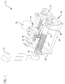
- Figure 1 is a perspective view of an assembled spinal implant cutting apparatus according to one or more embodiments of the present invention showing the spine implant holding a mandrel removed from the apparatus;
- Figure 2 is a perspective view showing a spinal implant being loaded onto a mandrel of a cutting apparatus according to one ore more embodiments of the present invention
- Figure 3 is a perspective view showing a spinal implant mounted on a mandrel of a cutting apparatus according to one or more embodiments of the present invention
- Figure 4 is a side perspective view showing a mandrel being mounted to a cutting apparatus according to one or more embodiments of the present invention
- Figure 5 is a side perspective view showing the mandrel mounted to the cutting apparatus according to one or more embodiments of the present invention.
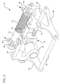
- Figure 6 is a rear perspective view showing the cutting blade being positioned using a caliper measurement according to one or more embodiments of the present invention
- Figure 7 is an enlarged perspective view showing indicia on a cutting fixture of the cutting apparatus according to one or more embodiments of the present invention.
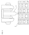
- Figure 8 is an enlarged partial perspective view showing a cutting blade in contact with a spinal implant according to one or more embodiments of the present invention.
- Figure 9 is a perspective view showing the operation of the cutting apparatus according to one or more embodiments.
- Figure 10 is a perspective view showing the cutting apparatus after the spinal implant has been cut and prior to removal of the mandrel according to one or more embodiments;
- Figure 11 is a perspective view showing removal of the spinal implant from the mandrel after the spinal implant has been cut according to one or more embodiments;
- Figure 12 is a perspective view showing the cut spinal implant being processed after cutting and prior to implantation according to one or more embodiments.
- Figure 13 is a bottom view of a blade used with a cutting apparatus according to one or more embodiments.
- the apparatus includes at least a first mandrel 12 configured to support a substantially cylindrical spinal implant 14.
- a cutting blade fixture 16 is mounted to the apparatus and configured to maintain a cutting blade 18 in a spaced apart relationship from the first mandrel 12.
- the cutting blade 18 can be positioned with respect to the first mandrel 12 to be in cutting engagement with the spinal implant 14 and to accurately cut the spinal implant 14 to a desired length.
- the spinal implant 14 mounted to the mandrel 12 is configured to be rotated with respect to the cutting blade 18.
- the mandrel 12 is shown in the Figures as being cylindrical in shape, it will be understood that the mandrel could have other shapes to support hollow spinal implants during cutting operations.
- the cross-sectional shape of the mandrel 12 could be triangular, square, hexagonal, or other shapes.
- mandrel 12 does not have to be a continuous mandrel as shown in the Figures.
- a pair of mandrels could be used to support the end portions of the spinal implant 14.
- the first mandrel 12 is configured to support a hollow spinal implant 14 such that the spinal implant 14 is slidably mounted on the first mandrel 12.
- a pin 20 or other suitable holding element is provided to hold the spinal implant 14 on the mandrel 12 when the implant is being cut.
- Figure 3 shows the spinal implant 14 mounted on the mandrel 12 and the pin 20 as it is being placed to secure the implant 14 to the first mandrel 12.
- the apparatus 10 includes means for rotating the first mandrel 12.
- a handle 22 is provided for rotating the first mandrel 12.
- the handle 22 has a ratchet mechanism (not shown) associated with the handle for rotating the first mandrel 12. Ratchet mechanisms are known in the art, and a person skilled in the art can select an appropriate ratchet mechanism for rotating the first mandrel 12.
- the handle 22 can be moved in a back and forth (e.g., forward and backward or up and down) motion to cause the first mandrel 12 and the spinal implant 14 mounted thereon during the cutting operation, which will be described in more detail below.
- a back and forth motion e.g., forward and backward or up and down
- the first mandrel 12 and the spinal implant 14 mounted thereon can be moved in a back and forth (e.g., forward and backward or up and down) motion to cause the first mandrel 12 and the spinal implant 14 mounted thereon during the cutting operation, which will be described in more detail below.
- other devices can be used to rotate the first mandrel 12.
- the first mandrel 12 could be driven by a knob or crank attached to the end of the first mandrel 12, or alternatively, the first mandrel 12 could be rotated by a motor or other drive mechanism attached to the first mandrel 12.
- the cutting apparatus 10 includes a frame 24, which may include one or more mandrels including the first mandrel 12.
- the cutting fixture 16 is slidably mounted to the frame 24.
- the frame 24 may include a pair of support rods 26, 28.
- the apparatus 10 may further include a pair of mounting rods 30, 32 for mounting the cutting fixture 16 to the frame 24.
- the frame 24 may further include a pair of end members 34, 36, and the mandrel 12, and rods 26, 28, 30, 32 extend between the end members 34, 36.
- the apparatus 10 may further comprise a first reference point 38 associated with the frame 24, and in particular end member 36 and a second reference point 40 associated with the cutting fixture 16.
- the reference points 38, 40 are configured to permit placement of the cutting blade 18 such that the spinal implant 14 can be cut to a desired length.
- the reference points 38, 40 can be in any form suitable for the purpose of accurately referencing the length of the spinal implant 14 to be cut, and may be in the form of indicia, indentations, markings, holes, or notches.
- the reference points 38, 40 comprise a pair of notches configured to receive ends of an intervertebral caliper measurement device 42.
- the caliper 42 includes a pair of arms 44, 46, which can be used to obtain the distance between two vertebrae into which the spinal implant 14 is inserted after it has been cut to the desired size.
- a plurality of notches 40a, 40b, 40c are provided on the cutting fixture 16, each of the notches 40a, 40b, 40c may be referenced to a different sized spinal implant or spinal implant accessory such as an end cap for a spinal cage implant.
- the cutting blade 18 is readily removable from the cutting blade fixture 16.
- the cutting blade 18 may be held in place by a locking spring 50, which can be quickly moved between a locked and unlocked position to change the blade.
- the cutting blade fixture 16 and cutting blade 18 are configured to be positioned at a plurality of positions along the length of the spinal implant.
- the cutting blade fixture 16 can be mounted to the frame, and in particular it is slidably mounted on the parallel mounting mandrels 30, 32.
- the mounting mandrel 32 may include indicia, for example, grooves 52 providing cutting increments 54 thereon.
- the increments 54 on the mandrel 32 are matched to marked spacings or increments associated with the spinal implant.
- a locking knob 55 is provided on the cutting blade fixture 16 to lock and to release the cutting blade fixture on the mounting mandrel 30.
- the cutting blade fixture 16 and cutting blade 18 are movable in a direction substantially transverse to the longitudinal axis of the spinal implant 14, as indicated by arrow 56.
- the cutting blade fixture 16 may include an adjustment knob 58 or other suitable device that causes movement of the cutting blade 18 in the direction 56 substantially transverse to the longitudinal axis of the spinal implant.
- the adjustment knob 58 may be attached to a first end of threaded shaft (not shown), and the cutting blade 18 can be attached to the other end of the threaded shaft, and rotation of the knob 58 causes movement of the cutting blade fixture.
- One or more embodiments of the invention relates to a method of sizing a spinal implant.
- a practitioner for example, an orthopedic surgeon can conveniently use the cutting apparatus 10 described herein during a procedure involving the insertion of a spinal implant such as a spinal cage between two vertebrae.
- the apparatus of the present invention is particularly well-suited for cutting corpectomy cages, but the apparatus could also be adapted for cutting other types of substantially cylindrical spinal implants.
- Corpectomy cages are known in the art, and they typically comprise a central, substantially cylindrical body having a hollow interior.
- the apparatus 10 of the present invention is particularly useful for cutting corpectomy cages having an array of grooves spaced along the length of the cage that each circumscribe the outer circumference of the substantially cylindrical body.
- Corpectomy cages typically are used with end caps that are attached to each end of the substantially cylindrical body.
- the end plates are relatively flat structures with a central opening.
- the end plates can have different sizes to and angulations.
- Spinal implants are typically made of a biologically inert material, for example, any metal customarily used for surgical devices such as titanium or stainless steel. The invention is not limited to any particular material.
- mandrel 12 can be removably mounted to the apparatus 10, different diameter mandrels can be used to support different diameter cages.
- mandrels can be provided adapted to support 10 mm, 12 mm, 14 mm, 16 mm, 20 mm and 25 mm diameter cages having lengths between 10 mm and 120 mm. It will be understood, however, that the invention is not limited to cutting a spinal implant of any specific diameter or length.
- the apparatus 10 allows a practitioner to rapidly and easily transfer the measurement of the space between two vertebrae taken by the caliper to the cutting apparatus 10 so that the apparatus can quickly and easily cut the spinal implant.
- a practitioner uses a measurement device such as a caliper to obtain the distance between two vertebrae to obtain a desired length for the spinal implant.
- a measurement device such as a caliper to obtain the distance between two vertebrae to obtain a desired length for the spinal implant.
- an uncut spinal implant 14 is then mounted on a mandrel 12 associated with a cutting apparatus 10 including a cutting fixture 16 mounted to a frame 24, the cutting fixture including a cutting blade 18.
- the spinal implant 14 is in the form of a substantially cylindrical and hollow corpectomy cage, and the hollow cage is mounted to the mandrel 12 by sliding the cage over the mandrel 12.
- a pin 20 or other suitable holding device can be used to hold the spinal implant 14 on the mandrel 12.
- the holding structure or pin 20 can be inserted in one of a plurality of openings or holes contained in the spinal implant.
- the end members 34, 36 may include channels 60, 62 formed therein or separate brackets including channels for receiving the mandrel 12.
- the channels may be made from, or include inserts made from a friction reducing material such as plastic, for example PTFE or PEEK.
- a pair of thumbscrews 64, 66 or other suitable holding devices secure the mandrel 12 to the cutting apparatus 10.
- Other suitable holding devices include, but are not limited to, clips and holding pins.
- the calipers which have obtained the desired length of the spinal implant are inserted into the reference points 38, 40, while the cutting blade fixture 16 is released by loosening the locking knob 55, and the cutting fixture is moved along the mounting mandrels 30, 32 until the spacing between the cutting blade 18 and end of the spinal implant 14 approximately equals the distance between the arms 44, 46 of the caliper 42.
- the caliper arm 46 is placed on reference point 38, and the cutting fixture 16 is adjusted until spacing between the caliper arms and the reference marks is equal.
- the locking knob 55 is then tightened to lock the cutting fixture 16 and cutting blade 18 in place to cut the spinal implant 14 to the desired length.
- a plurality of different reference points 40a, 40b, and 40c may be associated with the cutting fixture 16 to accommodate for different sized and shaped end caps for a spinal implant such as a corpectomy cage.
- the adjustment knob 58 is rotated to move the blade towards the spinal implant until the cutting blade 18 is in contact with the spinal implant 14 as shown in Figure 8.
- the first mandrel 12 is then rotated by moving the handle 22 in a back and forth motion until the cutting blade 18 cuts through the spinal implant.
- the thumbscrews 64, 66 are loosened, and the mandrel 12 is removed from the apparatus.
- the cut spinal implant 14 is then separated, and as shown in Figure 12, the cut end of the implant 14 is processed with a burr removing device 68 to remove any burrs at the end of the spinal implant 14.
- the implant 14 that has now been accurately cut to size is then inserted in between two vertebrae using procedures known in the art. End caps (not shown) are typically attached to the ends of the corpectomy cage to assist implantation of the cage in between two vertebral bodies.
Abstract
Description
- The invention relates to spinal implants, and in particular, methods and apparatus for cutting spinal implants.
- The spinal column is a highly complex system of bones and connective tissues that provides support for the body and protects the delicate spinal cord and nerves. The spinal column includes a series of stacked vertebral bodies, each vertebral body including an inner or central portion of relatively weak cancellous bone and an outer portion of relatively strong cortical bone. Situated between each vertebral body is an intervertebral disc that cushions and dampens compressive forces exerted upon the spinal column. A vertebral canal containing the spinal cord and nerves is located behind the vertebral bodies.
- A surgical technique commonly referred to as spinal fixation uses surgical implants for fusing together and/or mechanically immobilizing two or more vertebral bodies of the spinal column. Spinal fixation may also be used to alter the alignment of adjacent vertebral bodies relative to one another to change the overall alignment of the spinal column. Such techniques have been used effectively to treat a wide variety of conditions and, in most cases, to relieve pain.
- One spinal fixation technique involves the fusion of adjacent bone structures. Conventional procedures for a fusion procedure include partial or total excision of an injured disc portion, e.g., discectomy, and replacement of the excised disc with biologically acceptable plugs or bone wedges. The plugs are placed between adjacent vertebrae to maintain normal intervertebral spacing and to achieve, over a period of time, bony ingrowth or "fusion" with the plug and opposed vertebrae.
- Alternatively, a fusion cage may be inserted within a tapped bore or channel formed in the intervertebral space to stabilize the vertebrae and maintain a pre-defined intervertebral space. A pair of fusion cages may also be implanted within the intervertebral space. After a period of time, the soft cancellous bone of the surrounding vertebral bone structures infiltrates the cage through a series of apertures in the cage wall and unites with bone growth inducing substances disposed within an internal cavity of the cage wall to eventually form a solid fusion of the adjacent vertebrae.
- Presently existing fusion cages are sized to fit between adjacent vertebrae by cutting the cage to adjust the length of the cage. The length of the cage may also be adjusted by providing end caps, the position of which can be adjusted to alter the overall length of the cage. For example, United States patent number 6,344,057 describes a cylindrical fusion implant that has an adjustable length in that threaded end caps can be adjusted telescopically with respect to the cage. With regards to cutting fusion cages, there does not appear to be any convenient method and apparatus for quickly and accurately measuring and cutting the length of a fusion cage. Typically, a surgeon will use a caliper or other measuring device to determine the appropriate length of the spinal implant to fit in an intervertebral space, but there is no convenient way to transfer this measurement to a cutting device to make an accurate cut based on the intervertebral spacing measured by the caliper. It would be desirable to provide improved apparatus and methods for measuring and cutting spinal implants such as fusion cages to a desired length.
- In accordance with one or more embodiments of the present invention, a spinal implant cutting apparatus is provided. According to one embodiment, the apparatus comprises a first mandrel configured to support a moveable blade from a first position at which it is spaced from the spinal implant supported on the first mandrel and a second position at which it is in cutting engagement with the spinal implant. In one embodiment, the spinal implant is configured to be rotated with respect to the cutting blade. The first mandrel is configured to support a hollow spinal implant such that the spinal implant is slidably mounted on the first mandrel. As used herein, the term mandrel is not limited to mandrels that are cylindrical, and any shaped mandrel can be used to support the hollow spinal implant during cutting of the implant. In certain embodiments, the first mandrel is detachable from the apparatus to permit loading and removal of the spinal implant on the first mandrel.
- According to one or more embodiments, the mandrel is preferably rotatable about an axis, and means are provided for rotating the mandrel. Rotation of the mandrel can be accomplished by providing a handle associated with the first mandrel configured to rotate the first mandrel. According to certain embodiments, the handle may further include a ratchet mechanism to facilitate rotation of the first mandrel.
- In certain embodiments, the apparatus comprises a frame, and the cutting blade is part of a cutting fixture that is slidably mounted on the frame. In some embodiments, a first reference point is associated with the frame and a second reference point is associated with the cutting fixture. The reference points are preferably configured to permit placement of the cutting blade such that the spinal implant can be cut to a desired length. The reference points may comprise any convenient shape such as a pair of notches, slots, holes, indentation or the like configured to receive ends of an intervertebral caliper measurement device. In some embodiments, a plurality of reference points such as notches may be associated with the cutting fixture referenced to a plurality of different sized spinal implants.
- According to certain embodiments, the cutting blade is readily removable from the cutting fixture. In such embodiments, the cutting blade is held in place by a locking spring. In one or more embodiments, the cutting blade is configured to be positioned at a plurality of positions along the length of the spinal implant. In certain embodiments, the cutting fixture is mounted on a frame configured to permit the cutting blade to move in increments with respect to the spinal fixture. In such embodiments, the increments may be matched to marked spacings associated with the spinal implant. In certain preferred embodiments, the cutting blade fixture is movable in a direction substantially transverse to the longitudinal axis of the spinal implant. In these embodiments, an adjustment knob can be provided for this purpose, and rotation of the adjustment knob causes movement of the cutting blade substantially transverse to the longitudinal axis of the spinal implant.
- Another embodiment relates to a spinal implant cutting apparatus comprising a frame including a rotatable first mandrel for supporting a substantially cylindrical spinal implant and a cutting fixture including a cutting blade, the cutting fixture slidably mounted to the frame such that the cutting fixture can be moved to a plurality of positions along the length of the spinal implant and cut the spinal implant to a preselected length. In certain embodiments, the apparatus may further comprise indicia associated with the apparatus for receiving an intervertebral space measurement to accurately determine the length of the spinal implant. According to one or more embodiments, the spinal implant includes a substantially tubular cage.
- In other embodiments of the invention, a spinal implant cutting apparatus is provided which comprises a first mandrel removably attached to a frame, the removable mandrel adapted to receive a substantially tubular spinal implant, a cutting blade configured to be placed in cutting engagement with the spinal implant, and reference marks associated with the cutting blade and the apparatus are adapted to receive an intervertebral spacing measurement from a caliper.
- Still other embodiments of the invention relate to a method of sizing a spinal implant comprising using a measurement device to obtain the distance between two vertebrae to obtain a desired length for the spinal implant, mounting the spinal implant on a mandrel associated with a cutting apparatus including a cutting fixture mounted to a frame, the cutting fixture including a cutting blade, securing the mandrel to the cutting apparatus, positioning the cutting blade with respect to the spinal implant with reference to the distance obtained by the measurement device, and cutting the spinal implant to the desired length. According to certain method embodiments, positioning the cutting blade includes sliding the cutting fixture with respect to the spinal implant. The method may further comprise locking the cutting fixture in place. In preferred embodiments, the measurement device includes a caliper having a pair of arms. In certain embodiments, the apparatus includes a pair of reference marks associated with the ends of the spinal implant after it has been cut. In certain embodiments in which calipers are used as the measurement device, the spacing between the arms of the caliper corresponds to the desired length of the spinal implant. According to some embodiments, the method may further include placing the arms adjacent the reference marks to position the cutting blade for cutting the spinal implant to the desired length.
- In one or more embodiments of the method of the invention, the cutting blade is advanced towards the spinal implant so that the cutting blade and the spinal implant are in contact, and the mandrel is rotated until the blade cuts through the spinal implant. After the spinal implant has been cut, the cutting blade is moved away from the spinal implant. Thereafter, according to certain embodiments, the first mandrel can be removed from the apparatus after the spinal implant has been cut, and the cut spinal implant is removed from the first mandrel.
- According to other embodiments of the invention, a method of sizing a substantially cylindrical hollow spinal implant is provided comprising sliding the spinal implant on to a mandrel, measuring the size of the implant needed using a caliper having a pair of arms, the size of the implant corresponding to the distance between the arms, positioning a caliper with respect to the spinal implant and the cutting blade to determine the length of the implant to be cut, fixing the position of the cutting blade in relation to the spinal implant, and rotating the mandrel while the blade is in contact with the spinal implant until the cutting blade has cut through the spinal implant. In some embodiments, the spinal implant includes a spinal cage. According to one or more embodiments, the spinal cage includes circumferential grooves formed on the exterior surface of the cage and spaced along the length of the cage. In certain embodiments, the cutting blade is associated with a track and the blade can be moved in increments corresponding to the spacing between the circumferential grooves on the cage. In embodiments that include end pieces or end caps as part of a spinal cage assembly, the length of the cage will be adjusted to include the height of the end pieces. Thus, when a pair of calipers is used to measure the space between two vertebras, the size of the total implant will include the length of the cage plus the height of the cage.
- A more complete appreciation of the subject matter of the present invention and the various advantages thereof can be realized by reference to the following detailed description in which reference is made to the accompanying drawings in which:
- Figure 1 is a perspective view of an assembled spinal implant cutting apparatus according to one or more embodiments of the present invention showing the spine implant holding a mandrel removed from the apparatus;
- Figure 2 is a perspective view showing a spinal implant being loaded onto a mandrel of a cutting apparatus according to one ore more embodiments of the present invention;
- Figure 3 is a perspective view showing a spinal implant mounted on a mandrel of a cutting apparatus according to one or more embodiments of the present invention;
- Figure 4 is a side perspective view showing a mandrel being mounted to a cutting apparatus according to one or more embodiments of the present invention;
- Figure 5 is a side perspective view showing the mandrel mounted to the cutting apparatus according to one or more embodiments of the present invention;
- Figure 6 is a rear perspective view showing the cutting blade being positioned using a caliper measurement according to one or more embodiments of the present invention;
- Figure 7 is an enlarged perspective view showing indicia on a cutting fixture of the cutting apparatus according to one or more embodiments of the present invention;
- Figure 8 is an enlarged partial perspective view showing a cutting blade in contact with a spinal implant according to one or more embodiments of the present invention;
- Figure 9 is a perspective view showing the operation of the cutting apparatus according to one or more embodiments;
- Figure 10 is a perspective view showing the cutting apparatus after the spinal implant has been cut and prior to removal of the mandrel according to one or more embodiments;
- Figure 11 is a perspective view showing removal of the spinal implant from the mandrel after the spinal implant has been cut according to one or more embodiments;
- Figure 12 is a perspective view showing the cut spinal implant being processed after cutting and prior to implantation according to one or more embodiments; and
- Figure 13 is a bottom view of a blade used with a cutting apparatus according to one or more embodiments.
- Before describing several exemplary embodiments of the invention, it is to be understood that the invention is not limited to the details of construction or process steps set forth in the following description. The invention is capable of other embodiments and of being practiced or carried out in various ways.
- Referring now to the drawings and particularly to Figure 1, one or more embodiments of the invention relate to a spinal
implant cutting apparatus 10. The apparatus includes at least afirst mandrel 12 configured to support a substantially cylindricalspinal implant 14. Acutting blade fixture 16 is mounted to the apparatus and configured to maintain acutting blade 18 in a spaced apart relationship from thefirst mandrel 12. As will be described in more detail below, thecutting blade 18 can be positioned with respect to thefirst mandrel 12 to be in cutting engagement with thespinal implant 14 and to accurately cut thespinal implant 14 to a desired length. - As shown in Figure 1, the
spinal implant 14 mounted to themandrel 12 is configured to be rotated with respect to thecutting blade 18. Although themandrel 12 is shown in the Figures as being cylindrical in shape, it will be understood that the mandrel could have other shapes to support hollow spinal implants during cutting operations. For example, the cross-sectional shape of themandrel 12 could be triangular, square, hexagonal, or other shapes. In addition,mandrel 12 does not have to be a continuous mandrel as shown in the Figures. A pair of mandrels could be used to support the end portions of thespinal implant 14. Referring now to Figure 2, thefirst mandrel 12 is configured to support a hollowspinal implant 14 such that thespinal implant 14 is slidably mounted on thefirst mandrel 12. Apin 20 or other suitable holding element is provided to hold thespinal implant 14 on themandrel 12 when the implant is being cut. Figure 3 shows thespinal implant 14 mounted on themandrel 12 and thepin 20 as it is being placed to secure theimplant 14 to thefirst mandrel 12. - As shown in Figure 4, the
first mandrel 12 is detachable from the apparatus to permit loading and removal of thespinal implant 14 on thefirst mandrel 12. Referring again to Figure 1, in preferred embodiments, theapparatus 10 includes means for rotating thefirst mandrel 12. In the embodiment shown in the Figures, and in particular Figure 1, ahandle 22 is provided for rotating thefirst mandrel 12. Preferably, thehandle 22 has a ratchet mechanism (not shown) associated with the handle for rotating thefirst mandrel 12. Ratchet mechanisms are known in the art, and a person skilled in the art can select an appropriate ratchet mechanism for rotating thefirst mandrel 12. In use, thehandle 22 can be moved in a back and forth (e.g., forward and backward or up and down) motion to cause thefirst mandrel 12 and thespinal implant 14 mounted thereon during the cutting operation, which will be described in more detail below. It will be understood that other devices can be used to rotate thefirst mandrel 12. For example, thefirst mandrel 12 could be driven by a knob or crank attached to the end of thefirst mandrel 12, or alternatively, thefirst mandrel 12 could be rotated by a motor or other drive mechanism attached to thefirst mandrel 12. - In the embodiment shown in the Figures, the cutting
apparatus 10 includes aframe 24, which may include one or more mandrels including thefirst mandrel 12. In one or more embodiments, the cuttingfixture 16 is slidably mounted to theframe 24. In particular, theframe 24 may include a pair ofsupport rods apparatus 10 may further include a pair of mountingrods fixture 16 to theframe 24. Theframe 24 may further include a pair ofend members mandrel 12, androds end members - According to one or more embodiments, and as best shown in Figures 6 and 7, the
apparatus 10 may further comprise afirst reference point 38 associated with theframe 24, and inparticular end member 36 and asecond reference point 40 associated with the cuttingfixture 16. As will be described in more detail below, thereference points cutting blade 18 such that thespinal implant 14 can be cut to a desired length. Thereference points spinal implant 14 to be cut, and may be in the form of indicia, indentations, markings, holes, or notches. In the embodiment shown in the Figures, thereference points caliper measurement device 42. Thecaliper 42 includes a pair ofarms spinal implant 14 is inserted after it has been cut to the desired size. In preferred embodiments, a plurality ofnotches fixture 16, each of thenotches - Referring now to Figure 13, according to one or more embodiments, the
cutting blade 18 is readily removable from thecutting blade fixture 16. Thecutting blade 18 may be held in place by a lockingspring 50, which can be quickly moved between a locked and unlocked position to change the blade. - According to one ore more embodiments, the
cutting blade fixture 16 and cuttingblade 18 are configured to be positioned at a plurality of positions along the length of the spinal implant. Thecutting blade fixture 16 can be mounted to the frame, and in particular it is slidably mounted on theparallel mounting mandrels mandrel 32 may include indicia, for example,grooves 52 providingcutting increments 54 thereon. In preferred embodiments, theincrements 54 on themandrel 32 are matched to marked spacings or increments associated with the spinal implant. - A locking
knob 55 is provided on thecutting blade fixture 16 to lock and to release the cutting blade fixture on the mountingmandrel 30. - According to one or more embodiments of the invention and with reference to Figure 9, the
cutting blade fixture 16 and cuttingblade 18 are movable in a direction substantially transverse to the longitudinal axis of thespinal implant 14, as indicated byarrow 56. Thecutting blade fixture 16 may include anadjustment knob 58 or other suitable device that causes movement of thecutting blade 18 in thedirection 56 substantially transverse to the longitudinal axis of the spinal implant. Theadjustment knob 58 may be attached to a first end of threaded shaft (not shown), and thecutting blade 18 can be attached to the other end of the threaded shaft, and rotation of theknob 58 causes movement of the cutting blade fixture. - One or more embodiments of the invention relates to a method of sizing a spinal implant. In use, a practitioner, for example, an orthopedic surgeon can conveniently use the cutting
apparatus 10 described herein during a procedure involving the insertion of a spinal implant such as a spinal cage between two vertebrae. The apparatus of the present invention is particularly well-suited for cutting corpectomy cages, but the apparatus could also be adapted for cutting other types of substantially cylindrical spinal implants. Corpectomy cages are known in the art, and they typically comprise a central, substantially cylindrical body having a hollow interior. Theapparatus 10 of the present invention is particularly useful for cutting corpectomy cages having an array of grooves spaced along the length of the cage that each circumscribe the outer circumference of the substantially cylindrical body. Corpectomy cages typically are used with end caps that are attached to each end of the substantially cylindrical body. The end plates are relatively flat structures with a central opening. The end plates can have different sizes to and angulations. Spinal implants are typically made of a biologically inert material, for example, any metal customarily used for surgical devices such as titanium or stainless steel. The invention is not limited to any particular material. - Because the
mandrel 12 can be removably mounted to theapparatus 10, different diameter mandrels can be used to support different diameter cages. As a non-limiting example, mandrels can be provided adapted to support 10 mm, 12 mm, 14 mm, 16 mm, 20 mm and 25 mm diameter cages having lengths between 10 mm and 120 mm. It will be understood, however, that the invention is not limited to cutting a spinal implant of any specific diameter or length. Theapparatus 10 allows a practitioner to rapidly and easily transfer the measurement of the space between two vertebrae taken by the caliper to the cuttingapparatus 10 so that the apparatus can quickly and easily cut the spinal implant. - Therefore, in use, a practitioner uses a measurement device such as a caliper to obtain the distance between two vertebrae to obtain a desired length for the spinal implant. Referring to Figures 1 and 2, an uncut
spinal implant 14 is then mounted on amandrel 12 associated with a cuttingapparatus 10 including a cuttingfixture 16 mounted to aframe 24, the cutting fixture including acutting blade 18. In Figure 2, thespinal implant 14 is in the form of a substantially cylindrical and hollow corpectomy cage, and the hollow cage is mounted to themandrel 12 by sliding the cage over themandrel 12. Referring to Figure 3, apin 20 or other suitable holding device can be used to hold thespinal implant 14 on themandrel 12. The holding structure or pin 20 can be inserted in one of a plurality of openings or holes contained in the spinal implant. - Referring now to Figure 4 and 5, after the
spinal implant 14 has been mounted to themandrel 12, the mandrel is secured to the cutting apparatus. Theend members channels mandrel 12. The channels may be made from, or include inserts made from a friction reducing material such as plastic, for example PTFE or PEEK. A pair ofthumbscrews mandrel 12 to the cuttingapparatus 10. Other suitable holding devices include, but are not limited to, clips and holding pins. After themandrel 12 has been secured to theapparatus 10, thecutting blade 18 is positioned with respect to thespinal implant 14 with reference to the distance obtained by the measurement device. As shown in Figures 6 and 7, the calipers which have obtained the desired length of the spinal implant are inserted into thereference points cutting blade fixture 16 is released by loosening the lockingknob 55, and the cutting fixture is moved along the mountingmandrels blade 18 and end of thespinal implant 14 approximately equals the distance between thearms caliper 42. Thecaliper arm 46 is placed onreference point 38, and the cuttingfixture 16 is adjusted until spacing between the caliper arms and the reference marks is equal. The lockingknob 55 is then tightened to lock thecutting fixture 16 and cuttingblade 18 in place to cut thespinal implant 14 to the desired length. As shown in Figure 7, a plurality ofdifferent reference points fixture 16 to accommodate for different sized and shaped end caps for a spinal implant such as a corpectomy cage. - After the
cutting blade fixture 16 and cuttingblade 18 are locked in place with respect to the length of the cage, theadjustment knob 58 is rotated to move the blade towards the spinal implant until thecutting blade 18 is in contact with thespinal implant 14 as shown in Figure 8. As shown in Figure 9, thefirst mandrel 12 is then rotated by moving thehandle 22 in a back and forth motion until thecutting blade 18 cuts through the spinal implant. Referring now to Figure 10, thethumbscrews mandrel 12 is removed from the apparatus. As shown in Figure 11, the cutspinal implant 14 is then separated, and as shown in Figure 12, the cut end of theimplant 14 is processed with aburr removing device 68 to remove any burrs at the end of thespinal implant 14. Theimplant 14 that has now been accurately cut to size is then inserted in between two vertebrae using procedures known in the art. End caps (not shown) are typically attached to the ends of the corpectomy cage to assist implantation of the cage in between two vertebral bodies. - Although the invention herein has been described with reference to particular embodiments, it is to be understood that these embodiments are merely illustrative of the principles and applications of the present invention. For example, while the cutting blade shown in the preferred embodiments discussed herein is circular, it will be understood that other types of cutting blades can be used. For example, a straight cutting blade can be placed in fixed relation to the rotating mandrel, or a reciprocating blade could be used to cut the spinal implant. It is therefore to be understood that numerous modifications may be made to the illustrative embodiments and that other arrangements may be devised without departing from the spirit and scope of the present invention as defined by the appended claims and their equivalents.
Claims (20)
- A spinal implant cutting apparatus, characterized in that it comprises:a first mandrel (12) configured to support a substantially cylindrical spinal implant (14); anda cutting blade (18) moveable from a first position at which it is spaced from a spinal implant (14) supported on the first mandrel to a second position at which it is in cutting engagement with the spinal implant.
- The apparatus of claim 1, characterized in that the spinal implant (14) is configured to be rotated with respect to the cutting blade (18).
- The apparatus of claim 2, characterized in that the first mandrel (12) is configured to support a hollow spinal implant (14) such that the spinal implant is slidably mounted on the first mandrel.
- The apparatus of claim 3, characterized in that the first mandrel (12) is detachable from the apparatus to permit loading and removal of the spinal implant (14) on the first mandrel.
- The apparatus of claim 2, characterized in that it further comprises a handle (22) associated with the first mandrel and a ratchet mechanism associated with the handle (22) for rotating the first mandrel (12).
- The apparatus of claim 2, characterized in that it comprises a frame (24), the cutting blade (18) being slidably mounted to the frame (24).
- The apparatus of claim 6, characterized in that it further comprises a first reference point (38) associated with the frame (24) and a second reference point (40) associated with the cutting blade (18), the reference points being configured to permit placement of the cutting blade (18) such that the spinal implant (14) can be cut to a desired length.
- The apparatus of claim 7, characterized in that it further comprises a plurality of notches (40a, 40b, 40c) associated with the cutting blade referenced to a plurality of different sized spinal implants.
- The apparatus of claim 2, characterized in that it further comprises a cutting fixture (16) for securing the cutting blade (18), wherein the cutting blade (18) is readily removable from the cutting fixture (16).
- The apparatus of claim 9, characterized in that the cutting fixture (16) is mounted on a frame configured to permit the cutting blade to move in increments (54) with respect to the spinal fixture and the increments (54) are matched to marked spacings associated with spinal implant.
- The apparatus of claim 10, characterized in that the rotation of an adjustment knob (58) causes movement of the cutting blade (18) substantially transverse to the longitudinal axis of the spinal implant (14).
- The apparatus of claim 11, characterized in that the mandrel (12) is mounted in a pair of channels (60, 62) formed on the apparatus, the channels being made from a friction-reducing material.
- A spinal implant cutting apparatus, characterized in that it comprises:a first mandrel (12) removably attached to a frame (24), the removable mandrel adapted to receive a substantially tubular spinal implant (14);a cutting blade (18) configured to be placed in cutting engagement with the spinal implant (14); andreference marks (38, 40) associated with the cutting blade (18) and the apparatus adapted to receive an intervertebral spacing measurement from a caliper (42).
- A method of sizing a spinal implant (14, characterized in that the method comprises :using a measurement device (42) to obtain the distance between two vertebrae to obtain a desired length for the spinal implant (14);mounting the spinal implant (14) on a mandrel (12) associated with a cutting apparatus (10) including a cutting fixture (16) mounted to a frame, the cutting fixture (16) including a cutting blade (18);securing the mandrel (12) to the cutting apparatus (10);positioning the cutting blade (18) with respect to the spinal implant (14) with reference to the distance obtained by the measurement device (42) and cutting the spinal implant (14) to the desired length.
- The method of claim 14, characterized in that positioning the cutting blade (18) includes sliding the cutting fixture (16) with respect to the spinal implant (14).
- The method of claim 15, characterized in that the measurement device includes a caliper (42) having a pair of arms (44, 46).
- The method of claim 16, characterized in that it further comprises advancing the cutting blade (18) towards the spinal implant (14) so that the cutting blade and the spinal implant are in contact.
- The method of claim 17, characterized in that it further comprises rotating the first mandrel (12) and cutting through the spinal implant (14).
- A method of sizing a substantially cylindrical hollow spinal implant, characterized in that the method comprises:sliding the spinal implant (14) on to a mandrel (12);measuring the size of the implant needed using a caliper (42) having a pair of arms (44, 46), the size of the implant corresponding to the distance between the arms (44,46);positioning the caliper (42) with respect to the spinal implant (14) and the cutting blade (18) to determine the length of the implant to be cut;fixing the position of the cutting blade (18) in relation to the spinal implant (14); androtating the mandrel (12) while the blade (18) is in contact with the spinal implant (14) until the cutting blade has cut through the spinal implant.
- The method of claim 42, characterized in that the spinal implant (14) includes a spinal cage.
Priority Applications (4)
| Application Number | Priority Date | Filing Date | Title |
|---|---|---|---|
| DE60315680T DE60315680T2 (en) | 2003-12-16 | 2003-12-16 | Apparatus and method for separating vertebral implants. |
| EP03293189A EP1543800B1 (en) | 2003-12-16 | 2003-12-16 | Apparatus and method for cutting spinal implants |
| US10/808,817 US7347130B2 (en) | 2003-12-16 | 2004-03-25 | Apparatus and method for cutting spinal implants |
| PCT/EP2004/014806 WO2005058208A2 (en) | 2003-12-16 | 2004-12-01 | Apparatus and method for cutting spinal implants |
Applications Claiming Priority (1)
| Application Number | Priority Date | Filing Date | Title |
|---|---|---|---|
| EP03293189A EP1543800B1 (en) | 2003-12-16 | 2003-12-16 | Apparatus and method for cutting spinal implants |
Publications (2)
| Publication Number | Publication Date |
|---|---|
| EP1543800A1 true EP1543800A1 (en) | 2005-06-22 |
| EP1543800B1 EP1543800B1 (en) | 2007-08-15 |
Family
ID=34486479
Family Applications (1)
| Application Number | Title | Priority Date | Filing Date |
|---|---|---|---|
| EP03293189A Expired - Fee Related EP1543800B1 (en) | 2003-12-16 | 2003-12-16 | Apparatus and method for cutting spinal implants |
Country Status (4)
| Country | Link |
|---|---|
| US (1) | US7347130B2 (en) |
| EP (1) | EP1543800B1 (en) |
| DE (1) | DE60315680T2 (en) |
| WO (1) | WO2005058208A2 (en) |
Families Citing this family (14)
| Publication number | Priority date | Publication date | Assignee | Title |
|---|---|---|---|---|
| US7371260B2 (en) * | 2005-10-26 | 2008-05-13 | Biomet Sports Medicine, Inc. | Method and instrumentation for the preparation and transplantation of osteochondral allografts |
| US7819043B2 (en) * | 2006-06-27 | 2010-10-26 | Warsaw Orthopedic, Inc. | Devices and methods for cutting a vertebral implant |
| US8322256B2 (en) * | 2007-10-05 | 2012-12-04 | Biomet Manufacturing Corp. | System for forming a tendon-bone graft |
| US8303592B2 (en) * | 2007-10-05 | 2012-11-06 | Biomet Manufacturing Corp. | System for forming a tendon-bone graft |
| FR2940760B1 (en) | 2009-01-08 | 2010-12-31 | Memometal Technologies | ORTHOPEDIC IMPLANT FOR DIGITAL ARTHROPLASTY |
| FR2940759B1 (en) * | 2009-01-08 | 2011-10-07 | Memometal Technologies | INTRA MEDULLAIRE ANCHORING ROD FOR ORTHOPEDIC IMPLANT HEAD |
| US8506603B2 (en) | 2009-10-14 | 2013-08-13 | K2M, Inc. | Surgical rod scorer and method of use of the same |
| EP2488110B8 (en) * | 2009-10-14 | 2017-10-25 | K2M, Inc. | Surgical rod scorer and method of use of the same |
| US9144447B2 (en) | 2009-10-14 | 2015-09-29 | K2M, Inc. | Surgical rod scorer and method of use of the same |
| US9119659B2 (en) | 2011-12-03 | 2015-09-01 | Ouroboros Medical, Inc. | Safe cutting heads and systems for fast removal of a target tissue |
| US9393709B2 (en) * | 2012-06-26 | 2016-07-19 | K2M, Inc. | Mesh cage scoring and cutting system |
| CN105578975A (en) | 2013-07-19 | 2016-05-11 | 欧罗波罗斯医学有限公司 | An anti-clogging device for a vacuum-assisted, tissue removal system |
| CN111070262B (en) * | 2019-12-31 | 2021-06-29 | 浙江创城汽车零部件有限公司 | Production process based on intelligent automatic preparation of environment-friendly rubber for vehicles |
| US11559842B2 (en) * | 2020-08-06 | 2023-01-24 | Smart Skin Technologies Inc. | Cutting device |
Citations (8)
| Publication number | Priority date | Publication date | Assignee | Title |
|---|---|---|---|---|
| DE173215C (en) * | ||||
| US3748934A (en) * | 1971-11-08 | 1973-07-31 | M Lezberg | Control for a slitter |
| EP0129531A2 (en) * | 1983-06-17 | 1984-12-27 | N.V. Stewal S.A. | Process and device for producing a prosthesis |
| JPS60120042A (en) * | 1983-12-01 | 1985-06-27 | Uchiyama Mfg Corp | Manufacture of sealing material for bearing |
| US5702449A (en) * | 1995-06-07 | 1997-12-30 | Danek Medical, Inc. | Reinforced porous spinal implants |
| US6096081A (en) * | 1996-01-16 | 2000-08-01 | University Of Florida Tissue Bank, Inc. | Diaphysial cortical dowel |
| US6344057B1 (en) * | 1994-11-22 | 2002-02-05 | Sdgi Holdings, Inc. | Adjustable vertebral body replacement |
| US6442814B1 (en) * | 1999-04-23 | 2002-09-03 | Spinal Concepts, Inc. | Apparatus for manufacturing a bone dowel |
Family Cites Families (5)
| Publication number | Priority date | Publication date | Assignee | Title |
|---|---|---|---|---|
| US2125178A (en) * | 1935-10-29 | 1938-07-26 | Union Carbide & Carbon Corp | Billet surfacing process and machine |
| US3073193A (en) * | 1959-01-09 | 1963-01-15 | Reginald H Grant | Portable machine shop apparatus |
| US3363491A (en) * | 1964-05-15 | 1968-01-16 | Peter D. George | Modular lathes |
| US4057893A (en) * | 1976-04-07 | 1977-11-15 | Still-Walter Tool & Manufacturing Company | Milling table lathe |
| US6557226B1 (en) * | 1999-04-23 | 2003-05-06 | Michael E. Landry | Apparatus for manufacturing a bone dowel |
-
2003
- 2003-12-16 EP EP03293189A patent/EP1543800B1/en not_active Expired - Fee Related
- 2003-12-16 DE DE60315680T patent/DE60315680T2/en not_active Expired - Lifetime
-
2004
- 2004-03-25 US US10/808,817 patent/US7347130B2/en not_active Expired - Fee Related
- 2004-12-01 WO PCT/EP2004/014806 patent/WO2005058208A2/en active Application Filing
Patent Citations (8)
| Publication number | Priority date | Publication date | Assignee | Title |
|---|---|---|---|---|
| DE173215C (en) * | ||||
| US3748934A (en) * | 1971-11-08 | 1973-07-31 | M Lezberg | Control for a slitter |
| EP0129531A2 (en) * | 1983-06-17 | 1984-12-27 | N.V. Stewal S.A. | Process and device for producing a prosthesis |
| JPS60120042A (en) * | 1983-12-01 | 1985-06-27 | Uchiyama Mfg Corp | Manufacture of sealing material for bearing |
| US6344057B1 (en) * | 1994-11-22 | 2002-02-05 | Sdgi Holdings, Inc. | Adjustable vertebral body replacement |
| US5702449A (en) * | 1995-06-07 | 1997-12-30 | Danek Medical, Inc. | Reinforced porous spinal implants |
| US6096081A (en) * | 1996-01-16 | 2000-08-01 | University Of Florida Tissue Bank, Inc. | Diaphysial cortical dowel |
| US6442814B1 (en) * | 1999-04-23 | 2002-09-03 | Spinal Concepts, Inc. | Apparatus for manufacturing a bone dowel |
Non-Patent Citations (1)
| Title |
|---|
| PATENT ABSTRACTS OF JAPAN vol. 0092, no. 75 (M - 426) 2 November 1985 (1985-11-02) * |
Also Published As
| Publication number | Publication date |
|---|---|
| WO2005058208A2 (en) | 2005-06-30 |
| WO2005058208A3 (en) | 2005-08-25 |
| DE60315680D1 (en) | 2007-09-27 |
| US20050125986A1 (en) | 2005-06-16 |
| EP1543800B1 (en) | 2007-08-15 |
| US7347130B2 (en) | 2008-03-25 |
| DE60315680T2 (en) | 2008-06-05 |
Similar Documents
| Publication | Publication Date | Title |
|---|---|---|
| EP1543800B1 (en) | Apparatus and method for cutting spinal implants | |
| US11547443B2 (en) | Method and apparatus for minimally invasive insertion of intervertebral implants | |
| US20230157844A1 (en) | Method and apparatus for minimally invasive insertion of intervertebral implants | |
| EP0796593B1 (en) | Instrumentation for surgical implant insertion | |
| EP2268219B1 (en) | Expandable cage | |
| US8114088B2 (en) | Geared spinal implant inserter-distractor | |
| US7135024B2 (en) | Lumbar spine fixation device | |
| AU2002300898B2 (en) | Slaphammer tool | |
| US5716360A (en) | Patella recession instrument and method for anatomically-shaped patellar prostheses | |
| US7594932B2 (en) | Apparatus for anterior intervertebral spinal fixation and fusion | |
| US7625379B2 (en) | Methods and instrumentation for inserting intervertebral grafts and devices | |
| JP2003102741A (en) | Bone preparation instrument and preparation method | |
| JP2002540882A (en) | Spinal implant insertion method and instrument | |
| JPH0551304B2 (en) | ||
| US20140257489A1 (en) | Method and apparatus for minimally invasive insertion of intervertebral implants | |
| US20080011136A1 (en) | Method and apparatus for preparing bone grafts, including grafts for lumbar/thoracic interbody fusion | |
| EP1374781B1 (en) | A milling block for use in a vertebral body milling device | |
| US20060235418A1 (en) | Method and device for preparing a surface for receiving an implant | |
| JP2007528778A (en) | Techniques and instruments for intervertebral prosthesis implantation using independent positioning | |
| US9757135B1 (en) | Trephine reamer for use in removal of a femoral component of a hip replacement implant | |
| US20060276800A1 (en) | Intervertebral disc replacement and surgical instruments therefor | |
| WO2008008241A2 (en) | Method and apparatus for preparing bone grafts | |
| US11826268B2 (en) | Trial inserter and trial head | |
| US20240074876A1 (en) | Surgical cutter instrument with trial | |
| RU2751010C1 (en) | Apparatus for positioning container-type body implants |
Legal Events
| Date | Code | Title | Description |
|---|---|---|---|
| PUAI | Public reference made under article 153(3) epc to a published international application that has entered the european phase |
Free format text: ORIGINAL CODE: 0009012 |
|
| AK | Designated contracting states |
Kind code of ref document: A1 Designated state(s): AT BE BG CH CY CZ DE DK EE ES FI FR GB GR HU IE IT LI LU MC NL PT RO SE SI SK TR |
|
| AX | Request for extension of the european patent |
Extension state: AL LT LV MK |
|
| 17P | Request for examination filed |
Effective date: 20051207 |
|
| AKX | Designation fees paid |
Designated state(s): DE FR GB IT |
|
| GRAP | Despatch of communication of intention to grant a patent |
Free format text: ORIGINAL CODE: EPIDOSNIGR1 |
|
| GRAS | Grant fee paid |
Free format text: ORIGINAL CODE: EPIDOSNIGR3 |
|
| GRAA | (expected) grant |
Free format text: ORIGINAL CODE: 0009210 |
|
| AK | Designated contracting states |
Kind code of ref document: B1 Designated state(s): DE FR GB IT |
|
| REG | Reference to a national code |
Ref country code: GB Ref legal event code: FG4D |
|
| REF | Corresponds to: |
Ref document number: 60315680 Country of ref document: DE Date of ref document: 20070927 Kind code of ref document: P |
|
| PLBE | No opposition filed within time limit |
Free format text: ORIGINAL CODE: 0009261 |
|
| STAA | Information on the status of an ep patent application or granted ep patent |
Free format text: STATUS: NO OPPOSITION FILED WITHIN TIME LIMIT |
|
| 26N | No opposition filed |
Effective date: 20080516 |
|
| PG25 | Lapsed in a contracting state [announced via postgrant information from national office to epo] |
Ref country code: IT Free format text: LAPSE BECAUSE OF NON-PAYMENT OF DUE FEES Effective date: 20071231 |
|
| REG | Reference to a national code |
Ref country code: FR Ref legal event code: PLFP Year of fee payment: 13 |
|
| REG | Reference to a national code |
Ref country code: DE Ref legal event code: R082 Ref document number: 60315680 Country of ref document: DE Representative=s name: RGTH RICHTER GERBAULET THIELEMANN HOFMANN PATE, DE Ref country code: DE Ref legal event code: R081 Ref document number: 60315680 Country of ref document: DE Owner name: STRYKER EUROPEAN HOLDINGS I, LLC (N.D. GES. D., US Free format text: FORMER OWNER: STRYKER EUROPEAN HOLDINGS VI, LLC (N.D. GES. D. STAATES DELAWARE), KALAMAZOO, MICH., US Ref country code: DE Ref legal event code: R081 Ref document number: 60315680 Country of ref document: DE Owner name: STRYKER EUROPEAN HOLDINGS I, LLC (N.D. GES. D., US Free format text: FORMER OWNER: STRYKER SPINE, CESTAS, FR |
|
| REG | Reference to a national code |
Ref country code: GB Ref legal event code: 732E Free format text: REGISTERED BETWEEN 20161006 AND 20161012 |
|
| REG | Reference to a national code |
Ref country code: GB Ref legal event code: 732E Free format text: REGISTERED BETWEEN 20161013 AND 20161019 |
|
| REG | Reference to a national code |
Ref country code: FR Ref legal event code: PLFP Year of fee payment: 14 |
|
| REG | Reference to a national code |
Ref country code: FR Ref legal event code: TP Owner name: STRYKER EUROPEAN HOLDINGS I, LLC, US Effective date: 20161108 |
|
| REG | Reference to a national code |
Ref country code: FR Ref legal event code: PLFP Year of fee payment: 15 |
|
| PGFP | Annual fee paid to national office [announced via postgrant information from national office to epo] |
Ref country code: DE Payment date: 20181204 Year of fee payment: 16 |
|
| PGFP | Annual fee paid to national office [announced via postgrant information from national office to epo] |
Ref country code: FR Payment date: 20181120 Year of fee payment: 16 Ref country code: GB Payment date: 20181212 Year of fee payment: 16 |
|
| REG | Reference to a national code |
Ref country code: DE Ref legal event code: R119 Ref document number: 60315680 Country of ref document: DE |
|
| GBPC | Gb: european patent ceased through non-payment of renewal fee |
Effective date: 20191216 |
|
| PG25 | Lapsed in a contracting state [announced via postgrant information from national office to epo] |
Ref country code: FR Free format text: LAPSE BECAUSE OF NON-PAYMENT OF DUE FEES Effective date: 20191231 Ref country code: GB Free format text: LAPSE BECAUSE OF NON-PAYMENT OF DUE FEES Effective date: 20191216 Ref country code: DE Free format text: LAPSE BECAUSE OF NON-PAYMENT OF DUE FEES Effective date: 20200701 |