EP1542376A2 - MIMO receivers having one or more additional receive paths - Google Patents

MIMO receivers having one or more additional receive paths Download PDF

Info

Publication number
EP1542376A2
EP1542376A2 EP04257463A EP04257463A EP1542376A2 EP 1542376 A2 EP1542376 A2 EP 1542376A2 EP 04257463 A EP04257463 A EP 04257463A EP 04257463 A EP04257463 A EP 04257463A EP 1542376 A2 EP1542376 A2 EP 1542376A2
Authority
EP
European Patent Office
Prior art keywords
signals
signal
receive
subcarrier signals
carrier signals
Prior art date
Legal status (The legal status is an assumption and is not a legal conclusion. Google has not performed a legal analysis and makes no representation as to the accuracy of the status listed.)
Withdrawn
Application number
EP04257463A
Other languages
German (de)
French (fr)
Other versions
EP1542376A3 (en
Inventor
Adriaan Kamerman
Xiao-Jiao Tao
Isabella Modonesi
Tim Schenk
Allert Van Zelst
Current Assignee (The listed assignees may be inaccurate. Google has not performed a legal analysis and makes no representation or warranty as to the accuracy of the list.)
Agere Systems LLC
Original Assignee
Agere Systems LLC
Priority date (The priority date is an assumption and is not a legal conclusion. Google has not performed a legal analysis and makes no representation as to the accuracy of the date listed.)
Filing date
Publication date
Application filed by Agere Systems LLC filed Critical Agere Systems LLC
Publication of EP1542376A2 publication Critical patent/EP1542376A2/en
Publication of EP1542376A3 publication Critical patent/EP1542376A3/en
Withdrawn legal-status Critical Current

Links

Images

Classifications

    • HELECTRICITY
    • H04ELECTRIC COMMUNICATION TECHNIQUE
    • H04BTRANSMISSION
    • H04B7/00Radio transmission systems, i.e. using radiation field
    • H04B7/02Diversity systems; Multi-antenna system, i.e. transmission or reception using multiple antennas
    • H04B7/04Diversity systems; Multi-antenna system, i.e. transmission or reception using multiple antennas using two or more spaced independent antennas
    • H04B7/08Diversity systems; Multi-antenna system, i.e. transmission or reception using multiple antennas using two or more spaced independent antennas at the receiving station
    • H04B7/0837Diversity systems; Multi-antenna system, i.e. transmission or reception using multiple antennas using two or more spaced independent antennas at the receiving station using pre-detection combining
    • H04B7/0842Weighted combining
    • H04B7/0848Joint weighting
    • HELECTRICITY
    • H04ELECTRIC COMMUNICATION TECHNIQUE
    • H04JMULTIPLEX COMMUNICATION
    • H04J11/00Orthogonal multiplex systems, e.g. using WALSH codes
    • H04J11/0023Interference mitigation or co-ordination
    • H04J11/0026Interference mitigation or co-ordination of multi-user interference
    • H04J11/0036Interference mitigation or co-ordination of multi-user interference at the receiver
    • HELECTRICITY
    • H04ELECTRIC COMMUNICATION TECHNIQUE
    • H04BTRANSMISSION
    • H04B7/00Radio transmission systems, i.e. using radiation field
    • H04B7/02Diversity systems; Multi-antenna system, i.e. transmission or reception using multiple antennas
    • H04B7/04Diversity systems; Multi-antenna system, i.e. transmission or reception using multiple antennas using two or more spaced independent antennas
    • H04B7/0413MIMO systems
    • HELECTRICITY
    • H04ELECTRIC COMMUNICATION TECHNIQUE
    • H04LTRANSMISSION OF DIGITAL INFORMATION, e.g. TELEGRAPHIC COMMUNICATION
    • H04L27/00Modulated-carrier systems
    • H04L27/26Systems using multi-frequency codes
    • H04L27/2601Multicarrier modulation systems
    • H04L27/2647Arrangements specific to the receiver only

Abstract

In a multiple-input, multiple-output (MIMO) system, a receiver is implemented with at least one additional receive path beyond the number of transmit antennas used to transmit the signals (e.g., wireless OFDM signals) received at the receiver. In one embodiment, the additional receive path is used to reduced co-channel interference (CCI) in the recovered OFDM signals. In particular, each receive path applies recursive filtering to generate separate subcarrier signals. A processor converts the separate subcarrier signals from the different receive paths into a first set of subcarrier signals corresponding to each transmitted OFDM signal, where each first set of subcarrier signals has desired signal and possibly CCI. The processor also generates a second set of subcarrier signals corresponding to the CCI. The processor subtracts portions of the second set of subcarrier signals from each first set of subcarrier signals to generate recovered OFDM signals having reduced CCI.

Description

    Cross-Reference to Related Applications
  • This application claims the benefit of the filing date of U.S. provisional application no. 60/528,170, filed on 12/09/03, the teachings of which are incorporated herein by reference.
  • BACKGROUND OF THE INVENTION Field of the Invention
  • The present invention relates to wireless communications, and, in particular, to receivers for multiple-input, multiple-output (MIMO) systems, such as MIMO orthogonal frequency division multiplexing (OFDM) wireless local area network (WLAN) systems.
  • Description of the Related Art
  • In a conventional M×M MIMO-OFDM WLAN system, a transmitter with M transmit antennas transmits MOFDM signals (a type of multi-carrier signal) to a receiver having M receive paths that are used to generate M recovered versions of the transmitted OFDM signals.
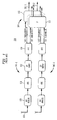
  • Fig. 1 shows a block diagram of the front end of a prior-art receiver 100 for use in a conventional 2x2 (i.e., M=2) MIMO-OFDM WLAN system. As shown in Fig. 1, 2x2 receiver 100 has two receive paths 102 and a processor 104. Each receive path 102 has a receive antenna 106, an RF/analog block 108, an analog-to-digital converter (ADC) 110, a cyclic-prefix (CP) removal block 112, and a fast Fourier transform (FFT) block 114.
  • Within each receive path 102, receive antenna 106 receives mixed versions of the M OFDM signals transmitted by a two-antenna MIMO-OFDM WLAN transmitter. In RF (radio frequency) implementations, RF/analog block 108 downconverts the analog RF OFDM signals from receive antenna 106 to an intermediate frequency (IF) or baseband, and ADC 110 digitizes the resulting downconverted analog OFDM signals to form a digital stream consisting of OFDM symbols separated by cyclic prefixes. CP removal block 112 removes the cyclic prefixes from between the OFDM symbols in the digital stream. FFT block 114 converts frames (e.g., 20 msec) of digital OFDM symbols in the time domain into frequency-domain coefficients for different OFDM subcarrier signals.
  • Processor 104 has a matrix 116 for each subcarrier in the multi-carrier OFDM signals. Each matrix 116 receives, from the different FFT blocks 114, all of the coefficients for one of the OFDM subcarriers. Note that the data from each FFT block 114 typically contains information for OFDM signals transmitted from all of the transmit antennas. Each matrix 116 is adapted to process the set of corresponding subcarrier coefficients to recover separate and equalized subcarrier coefficient streams 118, each different recovered subcarrier coefficient stream 118 corresponding to the OFDM signal transmitted from a different transmit antenna. Although not shown in Fig. 1, the recovered OFDM subcarrier coefficient streams 118 can then be processed using conventional OFDM decoding techniques, e.g., to detect the data encoded in the received OFDM signals.
  • One problem with MIMO-OFDM WLAN systems relates to co-channel interference (CCI), where a receiver simultaneously receives signals from spatial locations other than those of the transmitters of interest. CCI can occur when one or more additional transmitters operate at the same channels (e.g., using the same OFDM subcarriers) as the transmitters of interest, such that signals from the additional transmitter(s) interfere with the recovery of the desired signals from the transmitters of interest. Another scenario of CCI occurrence may be due to poor channel selectivity filtering of the receiver, where adjacent channel signals fold into the channel of the interest.
  • SUMMARY OF THE INVENTION
  • Problems in the prior art are addressed in accordance with the principles of the present invention by a MIMO-OFDM WLAN system having an M-antenna transmitter and a receiver having (M+1) receive paths. Advantageously, the additional receive path in the receiver of a MIMO-OFDM WLAN system can be used to reduce co-channel interference.
  • In one embodiment, the present invention is a receiver for receiving M multi-carrier signals transmitted from M transmit antennas, where M>1. The receiver comprises at least (M+1) receive paths and a processor. Each receive path is adapted to receive the M multi-carrier signals and separate the received signals into separate subcarrier signals, and the processor is adapted to process the separate subcarrier signals to generate a recovered version of each of the M transmitted multi-carrier signals.
  • BRIEF DESCRIPTION OF THE DRAWINGS
  • Other aspects, features, and advantages of the present invention will become more fully apparent from the following detailed description, the appended claims, and the accompanying drawings in which like reference numerals identify similar or identical elements.
  • Fig. 1 shows a block diagram of the front end of a prior-art receiver for use in a conventional 2x2 MIMO-OFDM WLAN systems;
  • Fig. 2 shows a block diagram of the front end of a receiver, according to one embodiment of the present invention; and
  • Fig. 3 shows a block diagram of a filter that can be used for each subcarrier in each filterbank of Fig. 2;
  • Fig. 4 shows the frequency response of the filter of Fig. 3; and
  • Fig. 5 shows a flow diagram of one possible successive cancellation algorithm for a 2x3 MIMO system.
  • DETAILED DESCRIPTION
  • Fig. 2 shows a block diagram of the front end of a receiver 200, according to one embodiment of the present invention. As shown in Fig. 2, receiver 200 has three receive paths 202 and a processor 204. Receiver 200 is designed to receive and process two OFDM signals transmitted from a transmitter having two transmit antennas, where the receiver generates recovered versions of those two OFDM signals. As such, in this particular embodiment, receiver 200 has one more receive path than the number of transmitted OFDM signals it is designed to recover.
  • Each receive path 202 has a receive antenna 206, an RF/analog block 208, an ADC 210, a CP removal block 212, and an FFT block 214, each of which is analogous to the corresponding element in the receive paths of prior-art receiver 100 of Fig. 1. In addition, however, each receive path 202 has a filterbank 216, which generates subcarrier coefficient streams in the frequency domain for application to processor 204.
  • Analogous to CP removal block 112 of Fig. 1, CP removal block 212 removes the cyclic prefixes from between the OFDM symbols in the digital stream received from ADC 210. In addition, however, CP removal block 212 provides these removed CP portions 218 from the guard-time intervals between consecutive OFDM symbols to filterbank 216. In alternative implementations, the entire digital stream from ADC 210 can be used by filterbank 216.
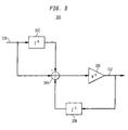
  • Fig. 3 shows a block diagram of a filter 300 that can be used for each subcarrier in each filterbank 216 of Fig. 2. Filter 300 comprises delays 302 and 308, summation node 304, and amplifier 306. Input signal 310 is applied to delay 302 and to summation node 304. Delay 302 delays input signal 310 for N cycles, where N is the size of the FFT and is typically set equal to the number of subcarriers. The output from delay 302 is inverted and applied to summation node 304. The output from summation node is output signal 312, which is also applied to amplifier 306. The output from amplifier 306 is applied to one-cycle delay 308, whose output is also applied to summation node 304.
  • The filtering of filter 300 for the kth subcarrier can be represented by the recursive relation of Equation (1) as follows:
    Figure 00030001
    where x(i + N) is input signal 310, Xk (i + 1) is output signal 312, and Xk (i) is given by Equation (2) as follows:
    Figure 00040001
    where W = e -j 2π N . Input signal 310 for filter 300 is indicated in Fig. 2 by signal 218, while filter 300 is initialized using the kth subcarrier signal 220 from FFT 214 of Fig. 2 as Xk (0) in Equation (1). Since W-k has a fixed value, amplifier 306 can be efficiently implemented using adders without requiring any multipliers.
  • Fig. 3 shows one possible filter structure for a discrete Fourier transform (DFT) filterbank. The DFT filterbank of Fig. 3 may be viewed as an (N-1)-tap finite impulse response (FIR) filter, whose frequency response sample is shown in Fig. 4. Those skilled in the art will understand that other possible implementations exist for filterbank 216. For example, filterbank 216 can be implemented using any suitable filter structure that implements a sliding-window DFT.
  • As shown in Fig. 2, the subcarrier coefficients from filterbank 216 of each receive path 202 are applied to corresponding P blocks 222 (also referred to as the master blocks) and P (pronounced "P-orthogonal") blocks 224 (also referred to as the slave blocks) of processor 204. Each P block 222 converts the three corresponding coefficient streams from the three receive paths into two (signal + CCI) coefficient streams 226, each corresponding to a different one of the two transmitted OFDM signals and each containing the corresponding desired signal as well as possibly co-channel interference. Meanwhile, each P block 224 converts the three corresponding coefficient streams from the three receive paths into a single CCI coefficient stream 228, corresponding to the possible co-channel interference. The operations of master and slave blocks P and P are estimated during the OFDM long-preamble training phase.
  • In a conventional, prior-art M×MMIMO-OFDM system, the master block (e.g., P matrix 116 of Fig. 1) performs an inverse of the estimated channel matrix H (i.e., P = H-1 ), where the channel matrix is estimated by sequentially physically placing M-1 spatial nulls to individually extract one desired signal at a time at one output port and then equalizing it.
  • In an MX(M+1) MIMO-OFDM of the present invention, H-1 does not exist, and the master block P has a slightly different meaning. If no CCI present in the long-preamble training phase, then the master block can be derived as a pseudo-inverse, generalized inverse, or Moore-Penrose inverse (i.e., P = H~) by performing additional maximum-ratio combining by adjusting the extra null available. This creates a possibility for diversity gain in a later decoding phase if CCI does not subsequently occur. If there is CCI during the long-preamble training phase, then the master block P performs interference cancellation by adjusting the extra available null. In this case, no diversity gain can be expected in the later decoding phase.
  • A single subcarrier can be modeled according to Equation (3) as follows: Y = SH + vJ + ε, where:
  • Y is the (M+1) matrix for the received symbol, where T is the number of transmitted training symbols per transmitter;
  • S is the T×M matrix for the known training symbol;
  • H is the (M+1) matrix for the unknown channel transfer function;
  • ν is the T× 1 vector for the unknown CCI;
  • J is the 1×(M+1) vector for the unknown CCI channel transfer function; and
  • ε is an T×(M+1) matrix, whose elements are identically independently distributed, complex, circularly symmetric, white Gaussian noise, ε i,j ~ N(0, σ2) .
  • Maximum likelihood estimation (MLE) may be used to solve Equation (3) because of its asymptotic optimality (in approaching the Cramer-Rao lower bound (CRLB)). Assuming white Gaussian noise, this is equivalent to least-square estimation (LSE) or a weighted version of LSE. Assuming the absence of CCI, the master block P can be represented according to Equation (4) as follows: P = H MLE ~ , where:
    Figure 00050001
    Since the training symbol S is known, the matrix S ~ = (SHS) -1SH can be calculated in advance and stored in memory , where SH is the Hermitian transpose of S.
  • Although singular value decomposition (SVD) can be used, the pseudo-inverse operation ([•]~ ) may also be calculated explicitly. Such an approach may be improved by using MLE in a general covariance case that models the unknown interference and white Gaussian noise as one multivariate, normally distributed noise. This can be shown to be equivalent to optimization of a determinant criterion.
  • Since the basic function of master blocks 222 is demultiplexing, an alterative approach may be a direct LS solution, as represented by Equation (6) as follows: P = min∥YP - S∥ = Y~S. This is referred to as partial channel inverse estimation, since the "CCI channel," a part of the channels for all received signals, is unknown. As shown in the following derivation, the result is an unbiased estimate.
  • Substituting Y = XG , where X = [S v] and G = [HH .JH ] H into Equation (6), yields Equation (7) as follows:
    Figure 00060001
    and the demultiplexed signals can be written according to Equation (8) as follows:
    Figure 00060002
    Note that Equation (8) has no bias term and no self-interference.
  • Unlike the approach of Equation (4), the solution to Equation (6) may require singular value decomposition, which may be implemented using the CORDIC-based VLSI architecture described by Y. Hu, "CORDIC-based VLSI architectures for digital signal processing," IEEE Signal Processing Magazine, vol. 9, no. 3, pp.16-35, July 1992, the teachings of which are incorporated herein by reference. The rank of Y may vary from 1 to M+1 depending on the channel condition and whether any CCI is present. If the repeated-preamble is adopted, then successive cancellation may be used.
  • Fig. 5 shows a flow diagram of one possible successive cancellation algorithm for a 2x3 MIMO system. First, at step 502, construct two signal null spaces as follows:
    Figure 00070001
    (null out TX1 when TX1 is on)
    Figure 00070002
    (null out TX2 when TX2 is on)
    where y1:2,i+1 denotes the received signals at the (i+1)th receiver when the first transmitter (TX1) is on, while y 3:4 ,i+1 denotes the received signals at the (i+1)th receiver when the second transmitter (TX2) is on.
  • Next, at step 504, obtain two spatially filtered signals as follows: X(1) = Y 1:2,1:3 Z 2 X(2) = Y3:4,1:3 Z 1
  • Next, at step 506, construct interference space as follows:
    Figure 00070003
    , (null out both TX1 and TX2)
  • Next, at step 508, construct signal combining and equalization as follows: E 1 = [e 1 e 2](e H 1 e 1 + e H 2 e 2)-1, E 2 = [e 3 e 4](e H 3 e 3 + e H 4 e 4)-1 where e 1 = S H 1:2,1 X (1) 1:2,1 S H 1:2,1 S 1:2,1 , e 2 = S H 1:2,1 X (1) 1:2,2 S H 1:2,1 S 1:2,1 , e 3 = S H 3:4,2 X (2) 1:2,1 S H 3:4,2 S 3:4,2 , e 4 = S H 3:4,2 X (2) 1:2,2 S H 3:4,2 S 3:4,2 ,
  • Next, at step 510, calculate the signal-to-noise&interference ratio (SNIR) as follows: SNIR = tr(SHS) (Y 1:2 Z 2 E 1 - S 1:2,1) H (Y 1:2 Z 2 E 1 - S 1:2,1) + (Y 3:4 Z 1 E 2 - S 3:4,2) H (Y 3:4 Z 1 E 2 - S 3:4,2)
  • Next, at step 512, if the SNIR is less than 22 (27dB), then there is CCI present, implying the following:
    Figure 00080001
  • Finally, at step 514, the master and slave blocks P and P are derived as follows: P = [Z 2 E 1 Z1E2 ] P = Z 2 Z 3
  • As shown in Fig. 2, the outputs from P blocks 222 and P1 blocks 224 are applied to corresponding CCI cancellation blocks 230, which apply a cancellation scheme to reduce the amount of CCI in the two coefficient streams 226 to generate corresponding output coefficient streams 232. In one implementation, each cancellation block 230 applies an adaptive scheme based on a typical Wiener-Hopf solution, where each pair of P blocks 222 are master blocks and the corresponding P block 224 is a slave block whose output 228 is used as a reference signal in the adaptive cancellation scheme. Information from each output coefficient stream 232 is fed back to determine how to distribute CCI coefficient stream 228 between the two (signal + CCI) coefficient streams 226.
  • In particular, each output coefficient stream 232 is fed back to a corresponding scaler 234, which applies an appropriate scale factor to CCI coefficient stream 228 based on the energy or power level of the output coefficient stream. The resulting scaled coefficient stream 236 is then subtracted from the corresponding (signal + CCI) coefficient stream 226 at a subtraction node 238 to generate the corresponding output coefficient stream 232. The scale factors can be calculated in a batch way (e.g., using direct projection) or in a recursive way (e.g., using a least mean squares (LMS) algorithm or a sign algorithm (SA)). SA is a simplified LMS, where only the sign of the error is fed back, while LMS also feeds back the magnitude of the error. See, e.g., Simon Haykin, Adaptive Filter Theory, (4th Edition), Prentice Hall, 2001 (ISBN: 0130901261), the teachings of which are incorporated herein by reference.
  • Although the present invention has been described in the context of a MIMO-OFDM WLAN system having a two-antenna transmitter and a receiver having three receive paths, the invention is not so limited. In general, the invention can be extended to any number M, where the system has an M-antenna transmitter and a receiver having (M+1) receive paths. Moreover, for a system having an M-antenna transmitter, the invention can be implemented as a receiver having more than (M+1) receive paths. These additional receive paths could be used to trade off between additional diversity gain and suppression of co-channel interference, where diversity gain refers to an increase in robustness against channel fading. Furthermore, with some minor modifications, the present invention can be implemented in the context of MIMO systems based on suitable modulation schemes other than OFDM, such as code-division multiple-access (CDMA) modulation. Similarly, the present invention can be implemented in the context of suitable systems other than WLANs, such as wireless wide area networks (WWANs). In addition to space-division multiplexing (SDM) schemes, where the M transmitter antennas are located within a single device, the present invention can also be implemented in the context of space-division multiple-access (SDMA) schemes, where the Mtransmitter antennas are not located within the same device, but rather in multiple devices corresponding to two or more different users.
  • The present invention may be implemented as circuit-based processes, including possible implementation as a single integrated circuit (such as an ASIC or an FPGA), a multi-chip module, a single card, or a multi-card circuit pack. As would be apparent to one skilled in the art, various functions of circuit elements may also be implemented as processing steps in a software program. Such software may be employed in, for example, a digital signal processor, micro-controller, or general-purpose computer.
  • The present invention can be embodied in the form of methods and apparatuses for practicing those methods. The present invention can also be embodied in the form of program code embodied in tangible media, such as floppy diskettes, CD-ROMs, hard drives, or any other machine-readable storage medium, wherein, when the program code is loaded into and executed by a machine, such as a computer, the machine becomes an apparatus for practicing the invention. The present invention can also be embodied in the form of program code, for example, whether stored in a storage medium, loaded into and/or executed by a machine, or transmitted over some transmission medium or carrier, such as over electrical wiring or cabling, through fiber optics, or via electromagnetic radiation, wherein, when the program code is loaded into and executed by a machine, such as a computer, the machine becomes an apparatus for practicing the invention. When implemented on a general-purpose processor, the program code segments combine with the processor to provide a unique device that operates analogously to specific logic circuits.
  • It will be further understood that various changes in the details, materials, and arrangements of the parts which have been described and illustrated in order to explain the nature of this invention may be made by those skilled in the art without departing from the scope of the invention as expressed in the following claims.
  • Although the steps in the following method claims, if any, are recited in a particular sequence with corresponding labeling, unless the claim recitations otherwise imply a particular sequence for implementing some or all of those steps, those steps are not necessarily intended to be limited to being implemented in that particular sequence.

Claims (10)

  1. A receiver for receiving M multi-carrier signals transmitted from M transmit antennas, M>1, the receiver comprising:
    at least (M+1) receive paths, each receive path adapted to receive the M multi-carrier signals and separate the received signals into separate subcarrier signals; and
    a processor adapted to process the separate subcarrier signals to generate a recovered version of each of the M transmitted multi-carrier signals.
  2. The invention of claim 1, wherein each receive path comprises:
    a receive antenna adapted to receive the multi-carrier signals;
    an analog-to-digital converter adapted to digitize the received multi-carrier signals; and
    a transform block adapted to convert the digitized multi-carrier signals in a time domain into the separate subcarrier signals in a frequency domain.
  3. The invention of claim 2, wherein the transform block comprises:
    a first transformer adapted to convert an initial set of the digitized multi-carrier signals into an initial set of separate subcarrier signals in the frequency domain; and
    a second transformer adapted to convert subsequent sets of the digitized multi-carrier signals into subsequent sets of separate subcarrier signals in the frequency domain based on the initial set of separate subcarrier signals.
  4. The invention of claim 3, wherein the second transformer is adapted to apply recursive filtering in converting the subsequent sets of the digitized multi-carrier signals into the subsequent sets of separate subcarrier signals.
  5. The invention of claim 4, wherein the recursive filtering of the second transformer is adapted to be initialized based on the initial set of separate subcarrier signals from the first transformer.
  6. The invention of claim 4, wherein the recursive filtering of the second transformer is based on a recursive relationship given by:
    Figure 00100001
    where x(i + N) is an input signal to the recursive filtering and Xk (i + 1) is an output signal from the recursive filtering.
  7. The invention of claim 1, wherein the processor comprises:
    a first processing block adapted to receive the separate subcarrier signals from each receive path and to generate M first signals, each first signal containing (1) desired signal corresponding to one of the transmit antennas and (2) interference;
    a second processing block adapted to receive the separate subcarrier signals from each receive path and to generate a second signal representative of the interference in the M first signals; and
    an interference cancellation block adapted to combine each first signal with a portion of the second signal to generate a recovered signal having less interference than said each first signal.
  8. The invention of claim 7, wherein:
    the first and second processing blocks are adapted to be trained using a successive cancellation algorithm; and
    the first and second processing blocks are adapted to be trained by:
    (1) constructing signal null-spaces;
    (2) obtaining spatially filtered signals;
    (3) constructing interference space;
    (4) constructing signal combining and interference;
    (5) calculating a signal-to-noise&interference ratio; and
    (6) generating relationships for the first and second processing blocks.
  9. A method for receiving M multi-carrier signals transmitted from M transmit antennas, M>1, the method comprising:
    receiving the M multi-carrier signals at at least (M+1) receive paths;
    separating, in each receive path, the received signals into separate subcarrier signals; and
    processing the separate subcarrier signals to generate a recovered version of each of the M transmitted multi-carrier signals.
  10. A wireless communications system comprising:
    a transmitter having M transmit antennas adapted to transmit M multi-carrier signals, M>1; and
    a receiver having:
    at least (M+1) receive paths, each receive path adapted to receive the M multi-carrier signals and separate the received signals into separate subcarrier signals; and
    a processor adapted to process the separate subcarrier signals to generate a recovered version of each of the Mtransmitted multi-carrier signals.
EP04257463A 2003-12-09 2004-12-01 MIMO receivers having one or more additional receive paths Withdrawn EP1542376A3 (en)

Applications Claiming Priority (4)

Application Number Priority Date Filing Date Title
US52817003P 2003-12-09 2003-12-09
US528170P 2003-12-09
US10/952,400 US7453949B2 (en) 2003-12-09 2004-09-28 MIMO receivers having one or more additional receive paths
US952400 2004-09-28

Publications (2)

Publication Number Publication Date
EP1542376A2 true EP1542376A2 (en) 2005-06-15
EP1542376A3 EP1542376A3 (en) 2009-06-24

Family

ID=34527126

Family Applications (1)

Application Number Title Priority Date Filing Date
EP04257463A Withdrawn EP1542376A3 (en) 2003-12-09 2004-12-01 MIMO receivers having one or more additional receive paths

Country Status (4)

Country Link
US (2) US7453949B2 (en)
EP (1) EP1542376A3 (en)
JP (1) JP4673616B2 (en)
KR (1) KR101114270B1 (en)

Cited By (2)

* Cited by examiner, † Cited by third party
Publication number Priority date Publication date Assignee Title
EP2129026A1 (en) * 2007-02-16 2009-12-02 NEC Corporation Radio transmission method and interference compensation method
CN103326979A (en) * 2012-03-21 2013-09-25 华为技术有限公司 Multi-carrier receiving device and method

Families Citing this family (13)

* Cited by examiner, † Cited by third party
Publication number Priority date Publication date Assignee Title
US7978759B1 (en) * 2005-03-24 2011-07-12 Marvell International Ltd. Scalable equalizer for multiple-in-multiple-out (MIMO) wireless transmission
WO2007043459A1 (en) 2005-10-07 2007-04-19 Nec Corporation Mimo radio communication system and method using a plurality of base stations and mobile stations
US20070098088A1 (en) * 2005-10-31 2007-05-03 Chih-Yuan Lin Equalizer applied in mimo-ofdm system and related method
KR101005617B1 (en) * 2005-12-08 2011-01-05 한국전자통신연구원 Receiver for ofdma system with multi-antenna, and method using the same
EP2005683A1 (en) * 2006-03-16 2008-12-24 Intel Corporation (INTEL) Method for channel estimation using recursive filtering and multicarrier receiver with interference-aware demodulation
GB2442263B (en) * 2006-09-26 2011-03-09 Iti Scotland Ltd Uwb apparatus and method
KR100873173B1 (en) * 2007-02-06 2008-12-10 인하대학교 산학협력단 System and Method for co-channel interference cancellation in cellular OFDM systems
US7675847B2 (en) * 2007-07-10 2010-03-09 Wipro Limited Hardware implementation of a programmable FFT based on a half length FFT core
US7970067B1 (en) 2007-10-31 2011-06-28 Samsung Electronics Co., Ltd. OFDM receiver and method for enhancing channel estimation performance in communication environment where high doppler frequency exists
KR101455992B1 (en) * 2007-11-14 2014-11-03 엘지전자 주식회사 Method for transmitting singnal in multiple antenna system
US8787762B2 (en) * 2011-02-22 2014-07-22 Nec Laboratories America, Inc. Optical-layer traffic grooming at an OFDM subcarrier level with photodetection conversion of an input optical OFDM to an electrical signal
JP6506919B2 (en) 2013-06-04 2019-04-24 三星電子株式会社Samsung Electronics Co.,Ltd. Interference control method in multi-hop network and relay node using the interference control method
CN106302273B (en) * 2016-08-12 2019-07-09 扬智科技股份有限公司 The processing method and its processing circuit of shared channel interference

Citations (4)

* Cited by examiner, † Cited by third party
Publication number Priority date Publication date Assignee Title
EP1043875A2 (en) * 1999-04-08 2000-10-11 NEC USA, Inc. Receiver for discrete multitone modulated signals having window function
EP1158716A2 (en) * 2000-05-22 2001-11-28 AT&T Corp. MIMO OFDM system
EP1185001A2 (en) * 2000-09-01 2002-03-06 Nortel Networks Limited Adaptive time deversity and spatial diversity for OFDM
WO2003041300A1 (en) * 2001-11-06 2003-05-15 Qualcomm Incorporated Multiple-access multiple-input multiple-output (mimo) communication system

Family Cites Families (20)

* Cited by examiner, † Cited by third party
Publication number Priority date Publication date Assignee Title
US4199660A (en) * 1977-11-07 1980-04-22 Communications Satellite Corporation FDM/TDM Transmultiplexer
US5991273A (en) * 1997-05-01 1999-11-23 Nortel Networks Corporation Determining SINR in a communications system
JP2000022838A (en) * 1998-06-30 2000-01-21 Fujitsu Ltd Delay suppressing system for subscriber's line transmission system
US6370129B1 (en) * 1999-06-28 2002-04-09 Lucent Technologies, Inc. High-speed data services using multiple transmit antennas
CN1152492C (en) * 1999-09-30 2004-06-02 富士通株式会社 Transmitter, receiver and transmitting method in multi-carrier transmission system
US6600796B1 (en) * 1999-11-12 2003-07-29 Lucent Technologies Inc. Method and apparatus for receiving wireless transmissions using multiple-antenna arrays
US6947509B1 (en) * 1999-11-30 2005-09-20 Verance Corporation Oversampled filter bank for subband processing
JP3857009B2 (en) * 2000-02-15 2006-12-13 三菱電機株式会社 Multi-carrier radio receiver and multi-carrier radio transmitter
EP1152576B8 (en) 2000-05-05 2009-12-23 Agere Systems, Inc. Joint estimation using the M-algorithm or T-algorithm in multiantenna systems
EP1152548A1 (en) 2000-05-05 2001-11-07 Lucent Technologies Inc. Increased data communication capacity of a high rate wireless network
DE60042408D1 (en) 2000-11-13 2009-07-30 Lucent Technologies Inc Channel estimation for space diversity communication systems
US8290098B2 (en) * 2001-03-30 2012-10-16 Texas Instruments Incorporated Closed loop multiple transmit, multiple receive antenna wireless communication system
US7706458B2 (en) * 2001-04-24 2010-04-27 Mody Apurva N Time and frequency synchronization in Multi-Input, Multi-Output (MIMO) systems
JP2003069529A (en) * 2001-08-28 2003-03-07 Nippon Telegr & Teleph Corp <Ntt> Device and method for ofdm signal reception and device and method for ofdm signal transmission
US7269127B2 (en) * 2001-10-04 2007-09-11 Bae Systems Information And Electronic Systems Integration Inc. Preamble structures for single-input, single-output (SISO) and multi-input, multi-output (MIMO) communication systems
US6636568B2 (en) * 2002-03-01 2003-10-21 Qualcomm Data transmission with non-uniform distribution of data rates for a multiple-input multiple-output (MIMO) system
US7197084B2 (en) * 2002-03-27 2007-03-27 Qualcomm Incorporated Precoding for a multipath channel in a MIMO system
US7327800B2 (en) * 2002-05-24 2008-02-05 Vecima Networks Inc. System and method for data detection in wireless communication systems
JP4412926B2 (en) * 2002-09-27 2010-02-10 株式会社エヌ・ティ・ティ・ドコモ Adaptive equalization apparatus and program thereof
US7317680B2 (en) * 2002-10-01 2008-01-08 Nortel Networks Limited Channel mapping for OFDM

Patent Citations (4)

* Cited by examiner, † Cited by third party
Publication number Priority date Publication date Assignee Title
EP1043875A2 (en) * 1999-04-08 2000-10-11 NEC USA, Inc. Receiver for discrete multitone modulated signals having window function
EP1158716A2 (en) * 2000-05-22 2001-11-28 AT&T Corp. MIMO OFDM system
EP1185001A2 (en) * 2000-09-01 2002-03-06 Nortel Networks Limited Adaptive time deversity and spatial diversity for OFDM
WO2003041300A1 (en) * 2001-11-06 2003-05-15 Qualcomm Incorporated Multiple-access multiple-input multiple-output (mimo) communication system

Non-Patent Citations (1)

* Cited by examiner, † Cited by third party
Title
ITO T ET AL: "Performance comparison of MF and MMSE combined iterative soft interference canceller and V-BLAST technique in MIMO/OFDM systems" VEHICULAR TECHNOLOGY CONFERENCE, 2003. VTC 2003-FALL. 2003 IEEE 58TH ORLANDO, FL, USA 6-9 OCT. 2003; [IEEE VEHICULAR TECHNOLGY CONFERENCE], PISCATAWAY, NJ, USA,IEEE, US, 6 October 2003 (2003-10-06), pages 488-492Vol.1, XP010701011 ISBN: 978-0-7803-7954-1 *

Cited By (4)

* Cited by examiner, † Cited by third party
Publication number Priority date Publication date Assignee Title
EP2129026A1 (en) * 2007-02-16 2009-12-02 NEC Corporation Radio transmission method and interference compensation method
EP2129026A4 (en) * 2007-02-16 2011-12-21 Nec Corp Radio transmission method and interference compensation method
US8805282B2 (en) 2007-02-16 2014-08-12 Nec Corporation Radio transmission system and interference compensation method
CN103326979A (en) * 2012-03-21 2013-09-25 华为技术有限公司 Multi-carrier receiving device and method

Also Published As

Publication number Publication date
EP1542376A3 (en) 2009-06-24
US7453949B2 (en) 2008-11-18
JP2005176376A (en) 2005-06-30
KR101114270B1 (en) 2012-03-05
US7672391B2 (en) 2010-03-02
JP4673616B2 (en) 2011-04-20
US20050122998A1 (en) 2005-06-09
KR20050056152A (en) 2005-06-14
US20090041153A1 (en) 2009-02-12

Similar Documents

Publication Publication Date Title
US7672391B2 (en) MIMO receivers having one or more additional receive paths
JP4847874B2 (en) Multi-user adaptive array receiver and method
Gao et al. Blind channel estimation for MIMO OFDM systems via nonredundant linear precoding
US7738607B2 (en) Method and system for cluster processing using conjugate gradient-based MMSE equalizer and multiple transmit and/or receive antennas for HSDPA, STTD, closed-loop and normal mode
US8000424B2 (en) Method and system for low complexity conjugate gradient based equalization in a wireless system
WO2011078726A1 (en) Method and apparatus for downlink multiuser mimo transmission in a wireless network
US20040142665A1 (en) Method and apparatus for diversity combining using a least squares approach
EP1530333A1 (en) Method for channel estimation in a MIMO OFDM system
JP5859913B2 (en) Wireless receiver, wireless transmitter, wireless communication system, program, and integrated circuit
Benjebbour et al. Performance of iterative successive detection algorithm with space-time transmission
US7050490B2 (en) Blind adaptive filtering method for receivers of communication systems
Gazzah et al. Blind ZF equalization with controlled delay robust to order over estimation
US8779979B2 (en) Multi-antenna signal receiving device processing multi-path interference
Seidel et al. A novel approach for combining local estimates for fully decentralized feedforward massive MIMO equalization: The multistep fusion
EP2244432A1 (en) Compensating carrier frequency offsets in OFDM systems
Moazzami et al. Application of a blind channel estimator for source separation in MIMO systems
Sarperi et al. Low-complexity ICA based blind multiple-input multiple-output OFDM receivers
Karkhanechi et al. EM-based channel estimation for space time block coded MIMO OFDM systems
Shi et al. Blind equalization of MIMO systems based on orthogonal constant modulus algorithm
Dong et al. MIMO channel estimation based on ambiguity resistant filtering and decimated feedback
Wang A recursive least-squares ASIC for broadband 8 x 8 multiple-input multiple-output wireless communications
Ma et al. Rake-based multiuser detection for quasi-synchronous SDMA systems
Singh et al. BER Comparison of MIMO Systems using Equalization Techniques in Rayleigh Flat Fading Channel
WO1999062197A1 (en) Communications receiver and method of detecting data from received signals
He et al. Blind identification of FIR channels in the presence of unknown noise

Legal Events

Date Code Title Description
PUAI Public reference made under article 153(3) epc to a published international application that has entered the european phase

Free format text: ORIGINAL CODE: 0009012

AK Designated contracting states

Kind code of ref document: A2

Designated state(s): AT BE BG CH CY CZ DE DK EE ES FI FR GB GR HU IE IS IT LI LT LU MC NL PL PT RO SE SI SK TR

AX Request for extension of the european patent

Extension state: AL BA HR LV MK YU

PUAL Search report despatched

Free format text: ORIGINAL CODE: 0009013

AK Designated contracting states

Kind code of ref document: A3

Designated state(s): AT BE BG CH CY CZ DE DK EE ES FI FR GB GR HU IE IS IT LI LT LU MC NL PL PT RO SE SI SK TR

AX Request for extension of the european patent

Extension state: AL BA HR LV MK YU

17P Request for examination filed

Effective date: 20091124

AKX Designation fees paid

Designated state(s): DE GB

17Q First examination report despatched

Effective date: 20100730

STAA Information on the status of an ep patent application or granted ep patent

Free format text: STATUS: THE APPLICATION IS DEEMED TO BE WITHDRAWN

18D Application deemed to be withdrawn

Effective date: 20101210