EP1540818B1 - Circuit arrangement and signal processing device - Google Patents
Circuit arrangement and signal processing device Download PDFInfo
- Publication number
- EP1540818B1 EP1540818B1 EP03747831A EP03747831A EP1540818B1 EP 1540818 B1 EP1540818 B1 EP 1540818B1 EP 03747831 A EP03747831 A EP 03747831A EP 03747831 A EP03747831 A EP 03747831A EP 1540818 B1 EP1540818 B1 EP 1540818B1
- Authority
- EP
- European Patent Office
- Prior art keywords
- resonator
- circuit
- circuit arrangement
- signal
- terminal
- Prior art date
- Legal status (The legal status is an assumption and is not a legal conclusion. Google has not performed a legal analysis and makes no representation as to the accuracy of the status listed.)
- Expired - Lifetime
Links
Images


Classifications
-
- H—ELECTRICITY
- H03—ELECTRONIC CIRCUITRY
- H03H—IMPEDANCE NETWORKS, e.g. RESONANT CIRCUITS; RESONATORS
- H03H7/00—Multiple-port networks comprising only passive electrical elements as network components
- H03H7/01—Frequency selective two-port networks
- H03H7/12—Bandpass or bandstop filters with adjustable bandwidth and fixed centre frequency
-
- G—PHYSICS
- G10—MUSICAL INSTRUMENTS; ACOUSTICS
- G10L—SPEECH ANALYSIS OR SYNTHESIS; SPEECH RECOGNITION; SPEECH OR VOICE PROCESSING; SPEECH OR AUDIO CODING OR DECODING
- G10L15/00—Speech recognition
- G10L15/28—Constructional details of speech recognition systems
- G10L15/285—Memory allocation or algorithm optimisation to reduce hardware requirements
Definitions
- the invention relates to a circuit arrangement and a signal processing apparatus.
- Sound signals have a high intensity range, ie a high dynamic range of up to 120dB.
- the noise of a rural area at night is about 20dB, whereas a rifle shot close to its origin has a sound level of about 140dB.
- the sound level is a physical quantity which is a measure of the intensity of the sound.
- the hearing adjusts its gain to the current sound level and is therefore able to cover a large dynamic range of sound levels between quiet and loud sound.
- a large sound level range is compressed to a small perceptible range. In this context one speaks of dynamic compression.
- the large dynamic range of the sound signals (up to 120 dB) is compressed to the limited dynamic range of the sensory cells or a neural system (about 40 dB).
- Speech recognition systems, hearing aids and audio data compression are economically interesting areas.
- the basics of automatic speech recognition can be found in [1], for example.
- Such a fast Fourier transform typically uses a time window of a given length, resulting in limited frequency and time resolution. If, as customary in speech recognition, only the magnitude spectrum is used, the time resolution is limited by the length of the time window used.
- the problem with using a time window of fixed size is that a change in the spectrum after the inverse transformation results in an error based on the finiteness of the time window.
- [3] discloses an apparatus for reducing the apparent volume of an output signal in a broadcasting system having a frequency-selective gain reduction network.
- [4] discloses circuitry for compressing the dynamic range of an input signal.
- the invention is based on the problem to provide a circuit arrangement and a signal processing apparatus, with which an improved dynamic compression is possible.
- the circuit arrangement comprises a resonator circuit for generating an output signal from an input signal.
- the resonator circuit includes a capacitance and an inductance, an input to which the input signal can be provided and an output to which the output signal can be provided.
- the circuit arrangement has a control circuit for controlling the quality of the resonator circuit, wherein the control circuit is set up such that it determines the quality of the resonator circuit as a function of the amplitude, preferably as a function of the signal waveform Signal amplitude, the input signal and / or the output signal controls or regulates.
- the quality is preferably controlled or regulated as a function of the signal amplitude of the signal amplitude, which clearly has the advantage that the time dependence of the input signal and / or the output signal itself is mapped to the time dependence of the quality, so that a quasi-instantaneous , Delay-free control of the quality is possible.
- controlling the quality is optional depending on the waveform of the signal amplitude, it is also possible to control the Q-factor depending on the amplitude.
- a signal processing device is provided with a circuit arrangement having the above-mentioned features. Furthermore, the signal processing device includes a further processing unit for processing the output signal.
- a basic idea of the invention is that the quality of the resonator circuit is adjusted based on the amplitude of the input or output signal. If one of these signals has a very high amplitude, the quality of the resonator circuit can be determined by means of the control circuit be reduced so much that the signal is greatly attenuated. On the other hand, with a signal of low amplitude, the quality can be increased so as to provide a very weakly attenuated signal at the output of the circuit arrangement.
- a resonator circuit near its resonant frequency acts as a sufficiently stable amplifier (resonance peaking) is used in accordance with the invention for carrying out dynamic compression.
- the quality of a resonator circuit is understood to mean the ratio of an amplitude of an output signal at or near the resonant frequency of the resonator circuit to the corresponding amplitude at a frequency which is greatly different from the resonant frequency.
- the quality of a resonator circuit depends on its ohmic resistance, so that the quality is adjustable, for example by means of controlling or regulating the ohmic resistance of the resonator circuit.
- control circuit In a scenario where the quality of the resonator circuit is adjusted based on the amplitude of the input signal introduced into the resonator circuit, the functionality of the control circuit may be referred to as a "control.” On the other hand, if the quality of the control circuit is set based on the amplitude of the output signal, the control circuit fulfills a "regulation" functionality, since it performs a feedback adjustment of the quality.
- a dynamically compressed output signal is generated, e.g. has significantly lower disturbing signal distortion compared to the inverse transformation of the logarithmized Fourier spectrum.
- sufficiently strong and intensity selective (e.g., non-linear) attenuation of an input signal is made possible by selectively reducing the quality of the resonator circuit.
- the circuit arrangement can be regarded as a filter circuit, wherein, based on the value of the inductance L and the capacitance C of the resonator circuit, the frequency range for which the resonator circuit is transparent is fixed.
- L, C an easy way is provided to set the frequency center of gravity of the transmissible interval of the resonator circuit.
- the width of the resonance curve of the resonator circuit is adjustable in particular by adjusting its quality.
- the resonator circuit in its interconnection according to the invention can be regarded as a filter with non-linear attenuation, with which in principle any desired high dynamic compression can be achieved. Due to a sufficiently narrowband processing, distortions that can arise due to excessive nonlinearity can be kept sufficiently low.
- the circuit arrangement as a filter may include a second order resonator circuit wherein the attenuation increases non-linearly with increasing sound level.
- a passive realization of the circuit arrangement that is to say when using passive components (coil L, capacitor C, ohmic resistor R), a stable circuit can be obtained (in contrast to systems which require an active, feedback amplifier).
- a filter bank is used according to the invention, instead of a logarithm, a nonlinear attenuation of an input signal based on the sound level of a signal is performed.
- FFT fast Fourier transform
- the resonator circuit may have a controllable (or controllable) by means of the control circuit ohmic resistance.
- a controllable or controllable ohmic resistance is a simple circuit component, by means of which the functionality of the regulation of the quality of the resonator circuit can be met with little effort and accurately and stably.
- the input signal may be provided between a first terminal of the ohmic resistor and a first terminal of the capacitance.
- the output signal may be provided between the first terminal of the capacitance and a second terminal of the capacitance.
- a second terminal of the ohmic resistance may be coupled to a first terminal of the inductance and a second terminal of the inductance may be coupled to a second terminal of the capacitance.
- the control circuit may be arranged to control the quality of the resonator circuit based on a Boltzmann function in which the amplitude of the output signal is included as a parameter.
- a Boltzmann function with a suitable choice of the parameters contained therein, is well suited to approximate the sensitivity curve of the outer hair cells in the human inner ear. A particularly good description of this biological dependence can be described by a second-order Boltzmann function. This makes it possible to approximate the sensitivity curve in the human ear, what for Applications of the circuit arrangement in the medical field (for example, for a hearing aid) is advantageous.
- the control circuit may be arranged to adjust the quality of the resonator circuit in response to the amplitude of the output signal based on a sensitivity characteristic determined for an ear of a human.
- a sensitivity characteristic of the human ear determined for example experimentally or theoretically, can be made accessible in the form of a file or table for the control circuit.
- the control circuit may control the quality of the resonator circuit to approximate the biological sensitivity characteristic stored therein.
- the control circuit may be arranged such that the higher the amplitude of the output signal, the lower the quality of the resonator circuit is set.
- the control circuit may be further configured such; that it adjusts the quality of the resonator circuit in a nonlinear dependence on the amplitude of the output signal. That is, signal portions of large amplitude are disproportionately attenuated to small amplitude signal portions. Thus, even with an extremely high range of sound levels in an input signal, compression can be achieved to a sufficiently narrow range in the output signal.
- the control circuit may be arranged to adjust the quality of the resonator circuit such that the amplitude of the output signal is within a predetermined interval. For certain applications, it may be advantageous to have the amplitude of an output signal to keep each case within a predetermined interval. This may be important in the context of data compression, for example, if a signal with a high intensity fluctuation is to be detected with as few quantization steps as possible. In this case, the control circuit may be arranged to control the quality of the resonator circuit such that the output signal is within the predetermined interval.
- the circuit arrangement may comprise a plurality of resonator circuits connected in series, wherein an output signal of a resonator circuit connected in each case can be provided as an input signal to the respectively following resonator circuit.
- a filter bank with a series-connected circuit comprising a plurality of resonator circuits is illustratively provided, whereby the dynamic compression can be extended to an even greater dynamic range.
- a sufficiently strong dynamic compression eg 60 dB
- a filter stage ie with a resonator circuit
- Q 1000
- a sufficiently strong dynamic compression eg of 60 dB
- the not too high individual quality of each of these filters has the advantageous effect that due to the resulting from the lower quality increased bandwidth of the individual filter, a larger frequency range of the filter is covered and simultaneously the impulse response of the Filter is improved, ie the input and release time of the system is much lower.
- the series-connected resonator circuits can be clearly coupled to each other directly such that the output voltage of an upstream resonator circuit is equal to the input voltage of the downstream resonator circuit and that the (usually different from zero in operation) output current of an upstream resonator Circuit is equal to the input current of the downstream resonator circuit.
- the circuit arrangement is usually free of an intermediate element between upstream and downstream resonator circuits. This can be realized by means of a circuit arrangement in which the second terminal of the coil of an upstream resonator circuit is coupled to the first terminal of the ohmic resistance of the resonator circuit connected downstream of the resonator circuit connected upstream.
- the series-connected resonator circuits can be clearly clear of an immediate coupling, ie decoupled from each other in a certain way, in particular with interposition of an intermediate element between the output of an upstream and input of a downstream resonator circuit.
- This is preferably realized in such a way that the output voltage of an upstream resonator circuit is equal to the input voltage of the resonator circuit connected downstream thereof and that the output current of an upstream resonator circuit is equal to zero.
- the input current of the downstream resonator circuit results essentially only from the impedance of this resonator circuit.
- an operational amplifier (as an impedance converter) between an upstream resonator circuit and the him provided downstream resonator circuit.
- a first input of the operational amplifier is coupled to the second terminal of the coil of the upstream resonator circuit.
- a second input of the operational amplifier is fed back to an output of the operational amplifier and is coupled to the first terminal of the ohmic resistance of the resonator circuit connected downstream of the preceding resonator circuit.
- the quality of all series-connected resonator circuits can be set identically.
- the computing power demanded by the control circuit is kept particularly low, since a common quality is determined and set for all resonator circuits, i. all filter parameters are identical.
- the quality of different series-connected resonator circuits can be set differently for the purpose of optimization. With such a circuit arrangement, the quality of each of the resonator circuits connected in series is thus individually set.
- the circuit arrangement preferably comprises a plurality of branches connected in parallel, each branch having a resonator circuit or a plurality of resonator circuits connected in series.
- the quality of a respective resonator circuit is controllable by means of the control circuit.
- a plurality of parallel-connected branches of resonator circuits are illustratively provided, wherein in each branch a plurality of resonator circuits can be connected in series.
- the at least one resonator circuit of each branch is arranged to be transparent to a respective frequency range of the input signal such that the branches are common for a contiguous frequency interval.
- the frequency range for which the human ear is sensitive is approximately between 20Hz and 20kHz.
- the frequency ranges of transmissible signals are generally different.
- the frequency range of transmissible signals in a resonator circuit is a distribution curve around the resonant frequency with a certain half width.
- the resonant frequency is clearly possible by adjusting the values L, C of the resonator circuit, the half-width is adjustable by adjusting the respective quality.
- the result is a preferably coherent frequency interval, by means of which the sensitivity range of the human ear or another frequency range of interest can be detected.
- the frequency ranges for which different branches are transmissive are at least partially overlapping each other. In this case, it is ensured that all frequencies are detected, and it is possible to assemble the signal components of individual branches.
- the frequency range for which a respective branch is permeable, by means of setting the value of the capacitance and / or the inductance of the at least one resonator circuit of the branch is predetermined. This is because the resonant frequency of a resonator circuit depends on the values of inductance and capacitance.
- the circuit arrangement of the invention is arranged to process an acoustic signal as an input signal.
- the circuit arrangement of the invention is suitable for use in a speech processing system. This can be based, for example, on pulsed neural networks, which rely on a reduction of the dynamic range. Further fields of application are systems for sound processing and (audio) data compression, if signals with high amplitudes are to be detected with as few quantization steps as possible. In addition, there are applications in the medical field, especially as hearing aid in patients with noise-deafness.
- the circuit arrangement according to the invention can be realized in digital or analog circuit technology.
- At least part of the circuit arrangement in particular the filters, the control or regulating functionality of the control circuit, can be realized as a computer program.
- the invention can be implemented both by means of a computer program, i. software, as well as by means of one or more special electrical circuits, i. in hardware or in any hybrid form, i. using software components and hardware components.
- a software implementation, in particular of the control circuit can be done for example in "C ++".
- a realization can take place on any processor or DSP (digital signal processor), as well as on an FPGA module.
- a FPGA Field Programmable Gate Array
- a FPGA is an integrated programmable circuit that typically has a plurality of programmable cells on a chip.
- the further processing unit may be a voice recognition device or a hearing device.
- the further processing unit as a hearing aid, in particular an application in question, in which a dynamic compression to compensate for disturbances in the volume perception of the hard of hearing is carried out.
- the outer hair cells may be affected, whereby the increase in sensitivity at low noise levels fails.
- the ear then clearly always works with the sensitivity provided for high sound levels. This results in the usable range of sound levels between the hearing threshold (very quiet) and the discomfort threshold (very loud) becoming smaller (recruitment).
- a dynamic compression can be performed by means of the circuit arrangement of the signal processing device according to the invention, which compresses the large sound level range of the acoustic environment on the perceived area of the patient clearly.
- the signal processing device may also form the input for a speech recognition system, particularly in pulsed neural network architecture.
- the signal processing device can be set up as an analogue or digital filter bank.
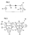
- Fig.1 a circuit arrangement 100 according to a preferred embodiment of the invention described.
- the circuit arrangement 100 includes a plurality of resonator circuits' 101, each having a capacitance and an inductance (not shown in FIG Fig.1 ), and an input at which an input signal can be provided and an output at which an output signal can be provided.
- Each three of the resonator circuits 101 are connected in series along a respective row of the matrix-shaped arrangement, so that a respective output of an upstream resonator circuit 101 is coupled to a respective input of a downstream resonator circuit 101.
- the values of the inductance and the capacitance of the resonator circuits 101 of one row are respectively selected such that the respective row can transmit a signal of a corresponding frequency interval in a surrounding area of the resonant frequency of the resonator circuits 101 of the row.
- Resonator circuits 101 of different rows each have different values for L, C, so that taken together, the individual rows or branches of resonator circuits 101 cover a continuous frequency interval corresponding to the sensitivity range of the human ear (approximately 20Hz to 20kHz).
- a control circuit 111 is in communication with all of the resonator circuits 101, that is, the control circuit 111 is coupled to all the resonator circuits.
- the quality of each of the resonator circuits 101 is adjustable by means of the control circuit 111 for controlling the quality of the resonator circuits 101, the control circuit 111 being arranged to depend on the quality of the resonator circuits 101 of the amplitude of an output signal of the last resonator circuit 101 of a respective line.
- the quality of the resonator circuits is R 11, R 12, R 13 set by the control circuit 111 based on the amplitude of a signal at the output of resonator circuit R. 13
- a sound source 103 which emits an acoustic signal as a global input signal 102. This is provided to the inputs of the resonator circuits 101 (R 11 , R 21, ..., R k1 , ..., R n1 ) of the first column of resonator circuits 101.
- the resonator circuit 101 R 11 arranged in the first row and the first column of resonator circuits is considered. This is provided at an input the global input signal 102 of the sound source 103.
- Resonator circuit 101 R 11 passes a frequency component of global input signal 102, which is dependent on its associated values L and C, and which is provided at an output of resonator circuit R 11 as first local output signal 104. Further, due to the functionality of the resonator circuit 101 R 11, the global input signal 102 is changed in amplitude depending on its (current) Q quality.
- the quality Q of the resonator circuit 101 R 11 is determined by means of an ohmic resistor (not shown in FIG Fig.1 ) of the resonator circuit 101 R 11 , wherein the control circuit 111 this controllable ohmic resistance provides a corresponding control signal, whereby the resistance is set to a predetermined value.
- the quality of the resonator circuit 101 is adjusted so that an input signal is more or less attenuated in a subsequent processing cycle according to this value of the quality.
- the circuit arrangement 100 is arranged for dynamic compression of the global input signal 102, signal regions of high amplitude are clearly weakened more than signal regions of a small amplitude.
- the first local output signal 104 is the R R provided to the resonator circuit 101 11 downstream resonator circuit 101 as a first local input signal 12 105th
- the first local input signal 105 passes through the resonator circuit 101 R 12 , wherein at an output the second local output signal 106 is provided.
- the second local output signal 106 serves as a second local input signal 107 of the resonator circuit 101 R 13 connected downstream of the resonator circuit 101 R 12 .
- a third local output signal 108 is provided.
- each of the resonator circuits 101 of a respective row of resonator circuits (R k1 , R k2 , R k3 )
- the quality of all the resonator circuits 101 of the row is determined based on the amplitude of the output signal at the output of the last resonator circuit ( in the k-th row resonator circuit R k3 ) is controlled by means of the control circuit 111.
- the composite global output signal 109 is thus subjected to dynamic compression relative to the global input signal 102.
- an input signal 200 is symbolized as voltage source U. Furthermore, an output signal 204 is symbolized as voltage U c .
- the input signal 200 is provided between a first terminal of an ohmic resistor 203 and a first terminal of a capacitor 201.
- the output signal 204 is provided between the first terminal of the capacitor 201 and a second terminal of the capacitor 201.
- a second terminal of the controllable ohmic resistor 203 is coupled to a first terminal of an inductor 202, and a second terminal Terminal of the inductance 202 is coupled to the second terminal of the capacitor 201.
- the value of the ohmic resistor R 203 is adjustable by means of the control circuit 111.
- the resonator circuit 101 off Fig.2 thus clearly represents a filter with adjustable damping.
- three (or generally N) resonator circuits 101 are connected in series behind each other as filter elements in each row.
- the time-dependent output signal U c (t), where t is the time, of an upstream filter defines in each case the input signal U 200 of the filter downstream of the upstream filter.
- the resistor R 203 can be changed in nonlinear dependence on the output voltage U c (t) (control), as a function of U c (t) of the respective upstream filter (control), or in all filters simultaneously as a function of U c (t) the last filter level of a row.
- Q (t) is the dependence of quality Q on time t.
- the Boltzmann function (1) approximates the sensitivity curve of the outer hair cells in the inner ear. If required, the function can be replaced by a second-order Boltzmann function, which, with the introduction of a further parameter, allows an even more exact adaptation. Equation (1) uses a simple first-order Boltzmann function because it has only one free parameter (namely SAT) and thus can be processed with little numerical effort.
- the time-dependent value of the ohmic resistance R (t) depends on the value of the inductance L and the capacitance C and the time-dependent quality Q (t).
- equations (1) and (2) form the regulation for setting the value R of the ohmic resistor 203 by means of the control circuit 111.
- the one of the in Fig.2 shown resonator circuit 101 is linear at very low amplitudes U c (t) (with Q ⁇ Q 0 for U c (t) ⁇ 0). Similarly, for very large amplitudes U c (t), it is approximately linear (Q ⁇ Q min for U c (t) ⁇ ⁇ ).
- the nonlinear Q is calculated independently for each filter frequency f 0 , ie for each row of resonator circuits 101. Referring to Fig.1 this means that each row of oscillator circuits 101 is assigned a corresponding filter frequency f 0 , for which the value of the quality Q (t) is calculated.
- a wave digital filter represents a class of digital filters with particularly favorable properties. They are modeled on traditional filters from the classical components of telecommunications engineering and are operated with the help of modern integrated digital circuits. According to the technology of a wave digital filter can vividly a analog model can be realized digitally (for example, using a computer).
- a first block 301 of the wave digital filter 300 contains a reflection-free serial coupler with the impedances R11 and R13.
- R11 represents the variable ohmic resistance R 203, based on a reference resistor.
- R12 represents a corrected resistance (impedance) of the coil L 202 with respect to a base frequency.
- a second block 302 includes a parallel coupler representing the parallel connection of the capacitance 201, the conductance values G21, G22, G23 being shown in the second block.
- G23 is an output conductance of the second block 302.
- the resistance of the capacitance C 201 is modeled.
- a third block 303 represents a memory or filter register for the capacitor 201 and a fourth block 304 represents a memory or a filter register for the coil 202.
- R ⁇ 11 R / R_B
- R ⁇ 12 2 ⁇ ⁇ F_B L / R_B tan ⁇ F_B / f_s
- R ⁇ 13 R ⁇ 11 + R ⁇ 12
- G ⁇ 21 R ⁇ 13 - 1
- G ⁇ 22 2 ⁇ ⁇ F_B C
- G ⁇ 23 G ⁇ 21 + G ⁇ 22
- R is the ohmic resistance 203 and R_B a predeterminable reference resistance.
- F_B is a predefinable reference frequency.
- the values R_B and F_B serve for scaling. Since the realization according to the described embodiment is realized with double precision float variables, this normalization is not relevant, but it is true if integer arithmetic is used.
- L is the inductance of the coil 202.
- the value f_s is a sampling frequency of the sampled time signal.
- the quantities R11, R12, R13 are ohmic resistances, whereas the magnitudes G21, G22 and G23 are conductances, that is to say inverse ohmic resistances.
- the initial values of the filter registers Z1 (fourth block 304) and Z2 (third block 303) are initialized to zero.
- the quantity U in equation (12) is the input signal 200.
- the output signal U c 204 is transferred as an input signal U 200 to the filtering stage 101 downstream of the filter stage 101 under consideration. Based on the output signal U c 204 of the last filter stage 101 of a row of filter stages 101, the quality to be set of the filters 101 connected in series is newly determined according to equation (1). From the value of the quality Q thus determined, the value of the damping determining resistor R is calculated according to equation (2). With the changed value of the ohmic resistor R 203, the filter resistances (R11, R12, R13, G21, G22, G23) and filter coefficients (gl, g2) according to equations (4) to (11). After this step, the output signal for a next time slice is calculated. In other words, the time spectrum can be broken down into several time slices, which are calculated successively numerically.
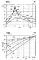
- Diagram 400 illustrates in which the functionality of the circuit arrangement according to the invention is shown according to a preferred embodiment of the invention.
- First to eighth curves 403 to 410 represent the frequency response (ie the respective value of the maximum amplitude of the filter output) of the inventive circuit arrangement for different signal amplitudes (relative to a reference amplitude).
- the first curve 403 corresponds to an amplitude of 1x10 -9
- the second curve 404 corresponds to an amplitude of 1 ⁇ 10 -4
- the third curve 405 corresponds to an amplitude of 1 ⁇ 10 -3
- the fourth curve 406 corresponds to an amplitude of 1 ⁇ 10 -2
- the fifth curve 407 corresponds to an amplitude of 1 ⁇ 10 -1
- the sixth curve 408 corresponds to an amplitude of 1 ⁇ 10 0
- the seventh curve 409 corresponds to an amplitude of 1 ⁇ 10 1
- the eighth curve 410 corresponds to an amplitude of 1 ⁇ 10 6 .
- Figure 5 describes the relationship between amplitudes of the input signal and the output signal of a circuit arrangement according to the invention.
- a sound pressure level A in in dB is plotted along an abscissa in logarithmic representation, based on a sound pressure of the reference variable 20 ⁇ Pa.
- the intensity of an output signal A OUT in dB is plotted in arbitrary units.
- a first curve 503 shows a linear growth function.
- a second curve 504 shows a growth function of the inner ear, ie the velocity of the basilar membrane relative to the sound pressure measured in front of the eardrum. The data of the second curve 504 is taken from [2].
- circuit arrangement 600 according to another preferred embodiment of the invention described.
- the circuit arrangement 600 is formed by a first resonator circuit 601 and a second resonator circuit 602, each of which is constructed as in FIG Fig.2 shown resonator circuit 101.
- the second resonator circuit 602 is connected downstream of the first resonator circuit 601.
- FIG. 6A the second terminal of the coil 202 of the upstream resonator circuit 601 is shown with the first terminal of the ohmic resistor 203 of FIG connected downstream resonator circuit 602 coupled.
- the output voltage U C1 of the upstream resonator circuit 601 is equal to the input voltage of the following resonator circuit 602. Further, the output current of the first resonator circuit 601 is equal to the input current of the second resonator circuit 602nd
- the values of the resistors R1 and R2, the inductors L1 and L2, and the capacitances C1 and C2, respectively, of the resonator circuits 601, 602 may be different from each other and / or regulated differently.
- 6B a realization of in 6A shown resonator circuits 601, 602 described as a wave digital filter 650.
- the wave digital filter 650 is formed by a first component 651, which represents the first resonator circuit 601, and a second component 652, which represents the second resonator circuit 602.
- a first component 651 which represents the first resonator circuit 601
- a second component 652 which represents the second resonator circuit 602.
- the two components 651, 652 in the 6B shown directly coupled together.
- the internal structure of each of the components 651, 652 is substantially the same as that of the wave digital filter 300 Figure 3 ,
- circuit arrangement 700 according to yet another embodiment of the invention described.
- the circuit arrangement 700 is formed by a first resonator circuit 701 and a second resonator circuit 702, which are connected in series.
- the resonator circuits 701, 702 are connected in series in a configuration that is decoupled from one another, that is to say that an intermediate element is connected between the resonator circuits 701 and 702.
- Each of the resonator circuits 701, 702 is basically constructed like that in FIG Fig.2
- a resonator circuit 101 is further provided between the first resonator circuit 701 and the second resonator circuit 702, wherein a noninverting input 703a of the operational amplifier 703 is coupled to the second terminal of the coil 202 of the upstream resonator circuit 701 is.
- an inverting input 703b of the operational amplifier 703 is fed back to its output 703c and coupled to the first terminal of the ohmic resistor 203 of the second resonator circuit 702 connected downstream of the first resonator circuit 701.
- the output voltage of the upstream resonator circuit 701 U C1 204 is equal to the input voltage of the second resonator circuit 702 connected downstream of the first resonator circuit 701.
- the output current of each resonator circuit is zero.
- the input current of the second resonator circuit 702 connected downstream of the upstream first resonator circuit 701 is based solely on the impedance of the downstream second resonator circuit 702 7A A realization of these circumstances by means of an impedance converter can be realized, which impresses the output voltage of the upstream resonator circuit 701 to the input of the downstream resonator circuit 702.
- the wave digital filter 750 is divided into a first component 751 and a second component 752, wherein the first component 751 represents the first resonator circuit 701, and wherein the second component 752 represents the second resonator circuit 702. Due to the functionality of the operational amplifier 703, the two components 751, 752 are clearly coupled to one another.
- the internal structure of each of the components 751, 752 substantially corresponds to that in FIG Figure 3 shown configuration.
- the input signal of the first component 751 is U
- the input signal of the second component 752 is U C1 .
Description
Die Erfindung betrifft eine Schaltkreis-Anordnung und eine Signalverarbeitungs-Vorrichtung.The invention relates to a circuit arrangement and a signal processing apparatus.
Schallsignale weisen einen hohen Intensitätsbereich auf, das heißt eine hohe Dynamik von bis zu 120dB. Die Geräuschkulisse einer ländlichen Gegend bei Nacht entspricht ungefähr 20dB, wohingegen ein Gewehrschuss in der Nähe des Entstehens einen Schallpegel von ungefähr 140dB aufweist.Sound signals have a high intensity range, ie a high dynamic range of up to 120dB. The noise of a rural area at night is about 20dB, whereas a rifle shot close to its origin has a sound level of about 140dB.
Aufgrund von Adaptionsprozessen im menschlichen Innenohr, bei denen die sogenannten äußeren Haarzellen eine wichtige Rolle spielen, erreicht das normale Gehör sowohl eine hohe Empfindlichkeit bei niedrigen Schallpegeln als auch eine hohe Toleranz bei hohen Schallpegeln. Der Schallpegel ist eine physikalische Größe, welche ein Maß ist für die Intensität des Schalls. Das Gehör passt seine Verstärkung dem aktuellen Schallpegel an und ist daher in der Lage, einen großen Dynamikbereich an Schallpegeln zwischen als leise empfundenem Schall und als laut empfundenem Schall abzudecken. Anschaulich wird ein großer Schallpegelbereich auf einen kleinen wahrnehmbaren Bereich zusammengedrückt. In diesem Zusammenhang spricht man von Dynamikkompression.Due to adaptation processes in the human inner ear, in which the so-called outer hair cells play an important role, normal hearing achieves both high sensitivity at low sound levels and high tolerance at high sound levels. The sound level is a physical quantity which is a measure of the intensity of the sound. The hearing adjusts its gain to the current sound level and is therefore able to cover a large dynamic range of sound levels between quiet and loud sound. Clearly, a large sound level range is compressed to a small perceptible range. In this context one speaks of dynamic compression.
Bei der Kodierung von Sprache in Aktionspotentiale des Hörnerven wird der große Dynamikbereich der Schallsignale (bis zu 120dB) auf den begrenzten dynamischen Bereich der Sinneszellen bzw. eines neuronalen Systems (etwa 40dB) komprimiert.When encoding speech into action potentials of the auditory nerve, the large dynamic range of the sound signals (up to 120 dB) is compressed to the limited dynamic range of the sensory cells or a neural system (about 40 dB).
Spracherkennungs-Systeme, Hörgeräte und Audio-Datenkomprimierung sind wirtschaftlich interessante Gebiete. Grundlagen der automatischen Spracherkennung sind beispielsweise [1] zu entnehmen.Speech recognition systems, hearing aids and audio data compression are economically interesting areas. The basics of automatic speech recognition can be found in [1], for example.
In einem bekannten Spracherkennungs-System wird eine schnelle Fourier-Transformation ("Fast Fourier Transformation", FFT) zur spektralen Analyse von Schallsignalen verwendet. Anschließend wird das erhaltene Amplitudenspektrum logarithmiert. Dies entspricht anschaulich einer Dynamikkompression mit logarithmischer Kennlinie.In a known speech recognition system, a fast Fourier transform (FFT) is used for the spectral analysis of sound signals. Subsequently, the obtained amplitude spectrum is logarithmized. This clearly corresponds to a dynamic compression with logarithmic characteristic.
Bei einer solchen schnellen Fourier-Transformation wird typischerweise ein Zeitfenster einer vorgegebenen Länge verwendet, was zu einer beschränkten Frequenz- und Zeitauflösung führt. Wird, wie in der Spracherkennung üblich, nur das Betragsspektrum verwendet, ist die Zeitauflösung durch die Länge des verwendeten Zeitfensters limitiert. Problematisch bei der Verwendung eines Zeitfensters fest vorgegebener Größe ist, dass bei einer Veränderung des Spektrums nach der Rücktransformation ein Fehler erhalten wird, der auf der Endlichkeit des Zeitfensters beruht.Such a fast Fourier transform typically uses a time window of a given length, resulting in limited frequency and time resolution. If, as customary in speech recognition, only the magnitude spectrum is used, the time resolution is limited by the length of the time window used. The problem with using a time window of fixed size is that a change in the spectrum after the inverse transformation results in an error based on the finiteness of the time window.
[3] offenbart eine Vorrichtung zum Verringern der scheinbaren Lautstärke eines Ausgabesignals in einem Rundfunksystem, die ein Frequenz-selektives Verstärkungsverringerungs-Netwerk aufweist.[3] discloses an apparatus for reducing the apparent volume of an output signal in a broadcasting system having a frequency-selective gain reduction network.
[4] offenbart eine Schaltungsanordnung zur Kompression des dynamischen Bereichs eines Eingabesignals.[4] discloses circuitry for compressing the dynamic range of an input signal.
Der Erfindung liegt das Problem zugrunde, eine Schaltkreis-Anordnung und eine Signalverarbeitungs-Vorrichtung bereitzustellen, mit denen eine verbesserte Dynamikkompression ermöglicht ist.The invention is based on the problem to provide a circuit arrangement and a signal processing apparatus, with which an improved dynamic compression is possible.
Das Problem wird gelöst durch eine Schaltkreis-Anordnung und durch eine Signalverarbeitungs-Vorrichtung mit den Merkmalen gemäß den unabhängigen Patentansprüchen.The problem is solved by a circuit arrangement and by a signal processing apparatus having the features according to the independent patent claims.
Die Schaltkreis-Anordnung weist einen Resonator-Schaltkreis zum Generieren eines Ausgabesignals aus einem Eingabesignal auf. Der Resonator-Schaltkreis enthält eine Kapazität und eine Induktivität, einen Eingang, an dem das Eingabesignal bereitstellbar ist und einen Ausgang, an dem das Ausgabesignal bereitstellbar ist. Ferner weist die Schaltkreis-Anordnung einen Steuer-Schaltkreis zum Steuern oder Regeln der Güte des Resonator-Schaltkreises auf, wobei der Steuer-Schaltkreis derart eingerichtet ist, dass er die Güte des Resonator-Schaltkreises abhängig von der Amplitude, vorzugsweise abhängig von dem Signalverlauf der Signalamplitude, des Eingabesignals und/oder des Ausgabesignals steuert oder regelt.The circuit arrangement comprises a resonator circuit for generating an output signal from an input signal. The resonator circuit includes a capacitance and an inductance, an input to which the input signal can be provided and an output to which the output signal can be provided. Furthermore, the circuit arrangement has a control circuit for controlling the quality of the resonator circuit, wherein the control circuit is set up such that it determines the quality of the resonator circuit as a function of the amplitude, preferably as a function of the signal waveform Signal amplitude, the input signal and / or the output signal controls or regulates.
Mit anderen Worten wird vorzugsweise die Güte abhängig von dem Signalverlauf der Signalamplitude gesteuert oder geregelt, was anschaulich den Vorteil mit sich bringt, dass die Zeitabhängigkeit des Eingabesignals und/oder des Ausgabesignals selbst auf die Zeitabhängigkeit der Güte abgebildet wird, so dass ein quasi-instantanes, verzögerungsfreies Steuern der Güte ermöglicht wird. Jedoch ist zu betonen, dass das Steuern der Güte abhängig von dem Signalverlauf der Signalamplitude optional ist, es ist auch möglich, die Güte abhängig von der Amplitude zu steuern oder zu regeln.In other words, the quality is preferably controlled or regulated as a function of the signal amplitude of the signal amplitude, which clearly has the advantage that the time dependence of the input signal and / or the output signal itself is mapped to the time dependence of the quality, so that a quasi-instantaneous , Delay-free control of the quality is possible. However, it should be emphasized that controlling the quality is optional depending on the waveform of the signal amplitude, it is also possible to control the Q-factor depending on the amplitude.
Darüber hinaus ist erfindungsgemäß eine Signalverarbeitungs-Vorrichtung mit einer Schaltkreis-Anordnung mit den oben genannten Merkmalen bereitgestellt. Ferner enthält die Signalverarbeitungs-Vorrichtung eine Weiterverarbeitungs-Einheit zum Weiterverarbeiten des Ausgabesignals.In addition, according to the invention a signal processing device is provided with a circuit arrangement having the above-mentioned features. Furthermore, the signal processing device includes a further processing unit for processing the output signal.
Eine Grundidee der Erfindung ist darin zu sehen, dass die Güte des Resonator-Schaltkreises basierend auf der Amplitude des Eingabe- oder Ausgabesignals eingestellt wird. Weist eines dieser Signale eine sehr hohe Amplitude auf, so kann mittels des Steuer-Schaltkreises die Güte des Resonator-Schaltkreises derart stark verringert werden, dass das Signal stark gedämpft wird. Dagegen kann bei einem Signal einer geringen Amplitude die Güte derart erhöht werden, dass ein nur sehr schwach gedämpftes Signal an dem Ausgang der Schaltkreis-Anordnung bereitgestellt wird.A basic idea of the invention is that the quality of the resonator circuit is adjusted based on the amplitude of the input or output signal. If one of these signals has a very high amplitude, the quality of the resonator circuit can be determined by means of the control circuit be reduced so much that the signal is greatly attenuated. On the other hand, with a signal of low amplitude, the quality can be increased so as to provide a very weakly attenuated signal at the output of the circuit arrangement.
Anschaulich wird erfindungsgemäß zum Durchführen einer Dynamikkompression die Tatsache verwendet, dass ein Resonator-Schaltkreis nahe seiner Resonanzfrequenz als ausreichend stabiler Verstärker wirkt (Resonanzüberhöhung).Illustratively, the fact that a resonator circuit near its resonant frequency acts as a sufficiently stable amplifier (resonance peaking) is used in accordance with the invention for carrying out dynamic compression.
Unter der Güte eines Resonator-Schaltkreises wird insbesondere das Verhältnis einer Amplitude eines Ausgabesignals bei oder nahe der Resonanzfrequenz des Resonator-Schaltkreises zu der entsprechenden Amplitude bei einer von der Resonanzfrequenz stark unterschiedlichen Frequenz verstanden. Die Güte eines Resonator-Schaltkreises hängt von dessen ohmschen Widerstand ab, so dass die Güte beispielsweise mittels Steuerns oder Regelns des ohmschen Widerstands des Resonator-Schaltkreises einstellbar ist.In particular, the quality of a resonator circuit is understood to mean the ratio of an amplitude of an output signal at or near the resonant frequency of the resonator circuit to the corresponding amplitude at a frequency which is greatly different from the resonant frequency. The quality of a resonator circuit depends on its ohmic resistance, so that the quality is adjustable, for example by means of controlling or regulating the ohmic resistance of the resonator circuit.
In einem Szenario, in dem die Güte des Resonator-Schaltkreises basierend auf der Amplitude des in den Resonator-Schaltkreis eingeführten Eingabesignals eingestellt wird, kann die Funktionalität des Steuer-Schaltkreises als ein "Steuern" bezeichnet werden. Wird dagegen die Güte des Steuer-Schaltkreises basierend auf der Amplitude des Ausgabesignals eingestellt, so erfüllt der Steuer-Schaltkreis eine "Regelungs"-Funktionalität, da er ein rückgekoppeltes Anpassen der Güte durchführt.In a scenario where the quality of the resonator circuit is adjusted based on the amplitude of the input signal introduced into the resonator circuit, the functionality of the control circuit may be referred to as a "control." On the other hand, if the quality of the control circuit is set based on the amplitude of the output signal, the control circuit fulfills a "regulation" functionality, since it performs a feedback adjustment of the quality.
Mit der erfindungsgemäßen Schaltkreis-Anordnung ist eine sichere und effektive Dynamikkompression eines Eingabesignals im Zeitbereich ermöglicht, ohne dass die Nachteile einer Fourier-Transformation auftreten. Insbesondere entfallen die bei einer Fourier-Transformation gemäß dem Stand der Technik auftretenden Probleme mit einem endlichen Zeitfenster.With the circuit arrangement according to the invention, a reliable and effective dynamic compression of an input signal in the time domain is made possible without the disadvantages of a Fourier transformation occurring. In particular, the problems with a finite time window occurring in a Fourier transformation according to the prior art are eliminated.
Darüber hinaus wird erfindungsgemäß ein dynamik komprimiertes Ausgangssignal generiert, das z.B. im Vergleich zu der Rücktransformation des logarithmierten Fourierspektrums deutlich geringere störende Signalverzerrung aufweist.Moreover, according to the invention, a dynamically compressed output signal is generated, e.g. has significantly lower disturbing signal distortion compared to the inverse transformation of the logarithmized Fourier spectrum.
Gemäß der Erfindung ist eine ausreichend starke und intensitätsselektive (z.B. nichtlineare) Dämpfung eines Eingabesignals mittels selektiven Verringerns der Güte des Resonator-Schaltkreises ermöglicht.According to the invention, sufficiently strong and intensity selective (e.g., non-linear) attenuation of an input signal is made possible by selectively reducing the quality of the resonator circuit.
Anschaulich kann die Schaltkreis-Anordnung als Filter-Schaltkreis aufgefasst werden, wobei basierend auf dem Wert der Induktivität L und der Kapazität C des Resonator-Schaltkreises der Frequenzbereich festgelegt ist, für welchen der Resonator-Schaltkreis durchlässig ist. Somit ist mittels Einstellens der Werte L, C eine einfache Möglichkeit geschaffen, den Frequenz-Schwerpunkt des transmittierbaren Intervalls des Resonator-Schaltkreises einzustellen. Die Breite der Resonanzkurve des Resonator-Schaltkreises ist insbesondere mittels Einstellens seiner Güte justierbar. Der Resonator-Schaltkreis in seiner erfindungsgemäßen Verschaltung kann als Filter mit nichtlinearer Dämpfung angesehen werden, mit dem eine im Prinzip beliebig hohe Dynamikkompression erreicht werden kann. Aufgrund einer ausreichend schmalbandigen Verarbeitung können auch Verzerrungen, die durch eine zu starke Nichtlinearität entstehen können, ausreichend gering gehalten werden.Illustratively, the circuit arrangement can be regarded as a filter circuit, wherein, based on the value of the inductance L and the capacitance C of the resonator circuit, the frequency range for which the resonator circuit is transparent is fixed. Thus, by setting the values L, C, an easy way is provided to set the frequency center of gravity of the transmissible interval of the resonator circuit. The width of the resonance curve of the resonator circuit is adjustable in particular by adjusting its quality. The resonator circuit in its interconnection according to the invention can be regarded as a filter with non-linear attenuation, with which in principle any desired high dynamic compression can be achieved. Due to a sufficiently narrowband processing, distortions that can arise due to excessive nonlinearity can be kept sufficiently low.
Die Schaltkreis-Anordnung als Filter kann einen Resonator-Schaltkreis zweiter Ordnung enthalten, wobei die Dämpfung nichtlinear mit steigendem Schallpegel ansteigt. Bei einer passiven Realisierung der Schaltkreis-Anordnung, das heißt bei einer Verwendung passiver Bauelemente (Spule L, Kondensator C, ohmscher Widerstand R) kann eine stabile Schaltung erhalten werden (im Gegensatz zu Systemen, die einen aktiven, rückgekoppelten Verstärker benötigen).The circuit arrangement as a filter may include a second order resonator circuit wherein the attenuation increases non-linearly with increasing sound level. In a passive realization of the circuit arrangement, that is to say when using passive components (coil L, capacitor C, ohmic resistor R), a stable circuit can be obtained (in contrast to systems which require an active, feedback amplifier).
Anstelle einer schnellen Fourier-Transformation (FFT) wird erfindungsgemäß eine, beispielsweise analoger, Filterbank verwendet, anstelle einer Logarithmierung wird eine nichtlineare Dämpfung eines Eingabesignals basierend auf dem Schallpegel eines Signals durchgeführt.Instead of a fast Fourier transform (FFT), a, for example analog, filter bank is used according to the invention, instead of a logarithm, a nonlinear attenuation of an input signal based on the sound level of a signal is performed.
Bevorzugte Weiterbildungen der Erfindung ergeben sich aus den abhängigen Ansprüchen.Preferred developments of the invention will become apparent from the dependent claims.
Der Resonator-Schaltkreis kann einen mittels des Steuer-Schaltkreises steuerbaren (bzw. regelbaren) ohmschen Widerstand aufweisen. Ein solcher steuerbarer oder regelbarer ohmscher Widerstand ist eine einfache Schaltkreis-Komponente, mittels welcher die Funktionalität des Regelns der Güte des Resonator-Schaltkreises mit geringem Aufwand und genau und stabil erfüllt werden kann.The resonator circuit may have a controllable (or controllable) by means of the control circuit ohmic resistance. Such a controllable or controllable ohmic resistance is a simple circuit component, by means of which the functionality of the regulation of the quality of the resonator circuit can be met with little effort and accurately and stably.
Das Eingabesignal kann zwischen einem ersten Anschluss des ohmschen Widerstands und einem ersten Anschluss der Kapazität bereitgestellt sein. Das Ausgabesignal kann zwischen dem ersten Anschluss der Kapazität und einem zweiten Anschluss der Kapazität bereitgestellt sein. Ein zweiter Anschluss des ohmschen Widerstands kann mit einem ersten Anschluss der Induktivität und ein zweiter Anschluss der Induktivität kann mit einem zweiten Anschluss der Kapazität gekoppelt sein.The input signal may be provided between a first terminal of the ohmic resistor and a first terminal of the capacitance. The output signal may be provided between the first terminal of the capacitance and a second terminal of the capacitance. A second terminal of the ohmic resistance may be coupled to a first terminal of the inductance and a second terminal of the inductance may be coupled to a second terminal of the capacitance.
Der Steuer-Schaltkreis kann derart eingerichtet sein, dass er die Güte des Resonator-Schaltkreises basierend auf einer Boltzmann-Funktion steuert, in welcher die Amplitude des Ausgabesignals als Parameter enthalten ist. Eine Boltzmann-Funktion ist bei geeigneter Wahl der darin enthaltenen Parameter gut geeignet, die Empfindlichkeitskurve der äußeren Haarsinneszellen im menschlichen Innenohr anzunähern. Eine besonders gute Beschreibung dieser biologischen Abhängigkeit kann durch eine Boltzmann-Funktion zweiter Ordnung beschrieben werden. Dadurch ist es möglich, die Empfindlichkeitskurve im menschlichen Ohr anzunähern, was für Anwendungen der Schaltkreis-Anordnung im medizinischen Bereich (beispielsweise für ein Hörgerät) vorteilhaft ist.The control circuit may be arranged to control the quality of the resonator circuit based on a Boltzmann function in which the amplitude of the output signal is included as a parameter. A Boltzmann function, with a suitable choice of the parameters contained therein, is well suited to approximate the sensitivity curve of the outer hair cells in the human inner ear. A particularly good description of this biological dependence can be described by a second-order Boltzmann function. This makes it possible to approximate the sensitivity curve in the human ear, what for Applications of the circuit arrangement in the medical field (for example, for a hearing aid) is advantageous.
Der Steuer-Schaltkreis kann derart eingerichtet sein, dass er die Güte des Resonator-Schaltkreises in Abhängigkeit von der Amplitude des Ausgabesignals basierend auf einer für ein Ohr eines Menschen ermittelten Empfindlichkeitscharakteristik einstellt. Um die Empfindlichkeitscharakteristik im Innenohr eines Menschen besonders gut mittels einer erfindungsgemäßen Schaltkreis-Anordnung nachzubilden, kann eine beispielsweise experimentell oder theoretisch ermittelte Empfindlichkeitscharakteristik des menschlichen Ohrs in der Form einer Datei oder Tabelle für den Steuer-Schaltkreis zugänglich abgelegt sein. In diesem Fall kann der Steuer-Schaltkreis die Güte des Resonator-Schaltkreises derart steuern oder regeln, dass die darin abgelegte biologische Empfindlichkeitscharakteristik angenähert wird.The control circuit may be arranged to adjust the quality of the resonator circuit in response to the amplitude of the output signal based on a sensitivity characteristic determined for an ear of a human. In order to simulate the sensitivity characteristic in the inner ear of a human being particularly well by means of a circuit arrangement according to the invention, a sensitivity characteristic of the human ear determined, for example experimentally or theoretically, can be made accessible in the form of a file or table for the control circuit. In this case, the control circuit may control the quality of the resonator circuit to approximate the biological sensitivity characteristic stored therein.
Der Steuer-Schaltkreis kann derart eingerichtet sein, dass er die Güte des Resonator-Schaltkreises umso geringer einstellt, je höher die Amplitude des Ausgabesignals ist.The control circuit may be arranged such that the higher the amplitude of the output signal, the lower the quality of the resonator circuit is set.
Der Steuer-Schaltkreis kann ferner derart eingerichtet sein; dass er die Güte des Resonator-Schaltkreises in einer nichtlinearen Abhängigkeit von der Amplitude des Ausgabesignals einstellt. D.h., dass Signalbereiche großer Amplitude überproportional stark gegenüber Signalbereichen kleiner Amplitude gedämpft werden. Somit kann auch bei einem extrem hohen Bereich von Schallpegeln in einem Eingabesignal eine Komprimierung auf einen ausreichend schmalen Bereich bei dem Ausgabesignal erreicht werden.The control circuit may be further configured such; that it adjusts the quality of the resonator circuit in a nonlinear dependence on the amplitude of the output signal. That is, signal portions of large amplitude are disproportionately attenuated to small amplitude signal portions. Thus, even with an extremely high range of sound levels in an input signal, compression can be achieved to a sufficiently narrow range in the output signal.
Der Steuer-Schaltkreis kann derart eingerichtet sein, dass er die Güte des Resonator-Schaltkreises derart einstellt, dass die Amplitude des Ausgabesignals innerhalb eines vorbestimmten Intervalls ist. Für bestimmte Anwendungen kann es vorteilhaft sein, die Amplitude eines Ausgabesignals auf jeden Fall innerhalb eines vorbestimmten Intervalls zu halten. Dies kann beispielsweise im Rahmen der Datenkomprimierung wichtig sein, wenn ein Signal mit einer hohen Intensitätsschwankung mit möglichst wenig Quantisierungsstufen erfasst werden soll. In diesem Fall kann der Steuer-Schaltkreis derart eingerichtet sein, dass er die Güte des Resonator-Schaltkreises derart steuert oder regelt, dass das Ausgabesignal innerhalb des vorbestimmten Intervalls liegt.The control circuit may be arranged to adjust the quality of the resonator circuit such that the amplitude of the output signal is within a predetermined interval. For certain applications, it may be advantageous to have the amplitude of an output signal to keep each case within a predetermined interval. This may be important in the context of data compression, for example, if a signal with a high intensity fluctuation is to be detected with as few quantization steps as possible. In this case, the control circuit may be arranged to control the quality of the resonator circuit such that the output signal is within the predetermined interval.
Die Schaltkreis-Anordnung kann eine Mehrzahl von in Serie geschalteten Resonator-Schaltkreisen aufweisen, wobei ein Ausgabesignal eines jeweils vorgeschalteten Resonator-Schaltkreises den ihm jeweils nachgeschalteten Resonator-Schaltkreis als Eingabesignal bereitstellbar ist.The circuit arrangement may comprise a plurality of resonator circuits connected in series, wherein an output signal of a resonator circuit connected in each case can be provided as an input signal to the respectively following resonator circuit.
Gemäß dieser besonders vorteilhaften Ausgestaltung ist anschaulich eine Filterbank mit einer Hintereinander-Schaltung aus mehreren Resonator-Schaltkreisen geschaffen, wodurch die Dynamikkompression auf einen noch größeren Dynamikbereich ausgeweitet werden kann. Im Prinzip kann eine ausreichend starke Dynamikkompression (z.B. 60dB) bereits mit einer Filterstufe (d.h. mit einem Resonator-Schaltkreis) mit einer sehr hohen Güte Q (z.B. Q=1000, die bei hohen Pegeln auf eine Güte von Q=1 reduziert wird) erfolgen. Eine solche Schaltkreis-Anordnung ist allerdings sehr schmalbandig (beispielsweise 0.1% der Resonanzfrequenz des Resonator-Schaltkreises). Mittels Kaskadierens mehrerer Filter (z.B. drei hintereinander geschaltete Filter) mit einer relativ geringen Güte Q (z.B. Q=10, so dass Q3=1000) lässt sich gemäß der Erfindung ebenfalls eine ausreichend starke Dynamikkompression (z.B. von 60dB) realisieren. Die nicht zu hohe Einzel-Güte von jedem dieser Filter bringt den vorteilhaften Effekt mit sich, dass aufgrund der aus der geringeren Güte resultierenden erhöhten Bandbreite der einzelnen Filter ein größerer Frequenzbereich der Filter abgedeckt wird und gleichzeitig das Impulsverhalten der Filter verbessert wird, d.h. die Ein- und Ausschwingzeit des Systems ist wesentlich geringer.In accordance with this particularly advantageous embodiment, a filter bank with a series-connected circuit comprising a plurality of resonator circuits is illustratively provided, whereby the dynamic compression can be extended to an even greater dynamic range. In principle, a sufficiently strong dynamic compression (eg 60 dB) can already be achieved with a filter stage (ie with a resonator circuit) with a very high quality Q (eg Q = 1000, which is reduced to a quality of Q = 1 at high levels) , However, such a circuit arrangement is very narrow band (for example, 0.1% of the resonant frequency of the resonator circuit). By means of cascading several filters (eg three filters connected in series) with a relatively low quality Q (eg Q = 10, so that Q 3 = 1000), a sufficiently strong dynamic compression (eg of 60 dB) can also be realized according to the invention. The not too high individual quality of each of these filters has the advantageous effect that due to the resulting from the lower quality increased bandwidth of the individual filter, a larger frequency range of the filter is covered and simultaneously the impulse response of the Filter is improved, ie the input and release time of the system is much lower.
Die hintereinander geschalteten Resonator-Schaltkreise können anschaulich miteinander direkt verkoppelt sein derart, dass die Ausgabespannung eines vorgeschalteten Resonator-Schaltkreises gleich der Eingabespannung des ihm nachgeschalteten Resonator-Schaltkreises ist und dass der (im Betrieb in der Regel von Null verschiedene) Ausgabestrom eines vorgeschalteten Resonator-Schaltkreises gleich dem Eingabestrom des ihm nachgeschalteten Resonator-Schaltkreises ist. Hierfür ist die Schaltkreis-Anordnung in der Regel von einem Zwischenelement zwischen vor- und nachgeschaltetem Resonator-Schaltkreisen frei. Dies ist mittels einer Schaltkreis-Anordnung realisierbar, bei welcher der zweite Anschluss der Spule eines vorgeschalteten Resonator-Schaltkreises mit dem ersten Anschluss des ohmschen Widerstands des dem vorgeschalteten Resonator-Schaltkreis nachgeschalteten Resonator-Schaltkreises gekoppelt ist.The series-connected resonator circuits can be clearly coupled to each other directly such that the output voltage of an upstream resonator circuit is equal to the input voltage of the downstream resonator circuit and that the (usually different from zero in operation) output current of an upstream resonator Circuit is equal to the input current of the downstream resonator circuit. For this purpose, the circuit arrangement is usually free of an intermediate element between upstream and downstream resonator circuits. This can be realized by means of a circuit arrangement in which the second terminal of the coil of an upstream resonator circuit is coupled to the first terminal of the ohmic resistance of the resonator circuit connected downstream of the resonator circuit connected upstream.
Alternativ können die hintereinander geschalteten Resonator-Schaltkreise anschaulich von einer unmittelbaren Kopplung frei sein, d.h. voneinander in gewisser Weise entkoppelt sein, insbesondere unter Zwischenschalten eines Zwischenelements zwischen Ausgabe eines vorgeschalteten und Eingabe eines nachgeschalteten Resonator-Schaltkreises. Dies ist vorzugsweise derart realisiert, dass die Ausgabespannung eines vorgeschalteten Resonator-Schaltkreises gleich der Eingabespannung des ihm nachgeschalteten Resonator-Schaltkreises ist und dass der Ausgabestrom eines vorgeschalteten Resonator-Schaltkreises gleich Null ist. Der Eingabestrom des nachgeschalteten Resonator-Schaltkreises ergibt sich im Wesentlichen nur aus der Impedanz des dieses Resonator-Schaltkreises. Bei einer derartigen Schaltkreis-Anordnung ist als Zwischenelement vorzugsweise ein Operationsverstärker (als Impedanzwandler) zwischen einem vorgeschalteten Resonator-Schaltkreis und dem ihm nachgeschalteten Resonator-Schaltkreis vorgesehen. Ein erster Eingang des Operationsverstärkers ist mit dem zweiten Anschluss der Spule des vorgeschalteten Resonator-Schaltkreises gekoppelt. Ein zweiter Eingang des Operationsverstärkers ist mit einem Ausgang des Operationsverstärkers rückgekoppelt und ist mit dem ersten Anschluss des ohmschen Widerstands des dem vorgeschalteten Resonator-Schaltkreis nachgeschalteten Resonator-Schaltkreises gekoppelt.Alternatively, the series-connected resonator circuits can be clearly clear of an immediate coupling, ie decoupled from each other in a certain way, in particular with interposition of an intermediate element between the output of an upstream and input of a downstream resonator circuit. This is preferably realized in such a way that the output voltage of an upstream resonator circuit is equal to the input voltage of the resonator circuit connected downstream thereof and that the output current of an upstream resonator circuit is equal to zero. The input current of the downstream resonator circuit results essentially only from the impedance of this resonator circuit. In such a circuit arrangement is preferably as an intermediate element, an operational amplifier (as an impedance converter) between an upstream resonator circuit and the him provided downstream resonator circuit. A first input of the operational amplifier is coupled to the second terminal of the coil of the upstream resonator circuit. A second input of the operational amplifier is fed back to an output of the operational amplifier and is coupled to the first terminal of the ohmic resistance of the resonator circuit connected downstream of the preceding resonator circuit.
Zur Reduktion der Rechenleistung kann die Güte aller in Serie geschalteter Resonator-Schaltkreise identisch eingestellt sein. In diesem Fall ist die von dem Steuer-Schaltkreis beanspruchte Rechenleistung besonders gering gehalten, da für alle Resonator-Schaltkreise eine gemeinsame Güte ermittelt und eingestellt wird, d.h. alle Filterparameter identisch sind. Wird eine Schaltkreis-Anordnung mit einer besonders hohen Qualitätsanforderung benötigt, so kann alternativ die Güte von unterschiedlichen in Serie geschalteten Resonator-Schaltkreisen zum Zwecke einer Optimierung unterschiedlich eingestellt werden. Bei einer solchen Schaltkreis-Anordnung ist somit die Güte von jedem der in Serie geschalteten Resonator-Schaltkreise individuell eingestellt.To reduce the computing power, the quality of all series-connected resonator circuits can be set identically. In this case, the computing power demanded by the control circuit is kept particularly low, since a common quality is determined and set for all resonator circuits, i. all filter parameters are identical. If a circuit arrangement with a particularly high quality requirement is required, alternatively the quality of different series-connected resonator circuits can be set differently for the purpose of optimization. With such a circuit arrangement, the quality of each of the resonator circuits connected in series is thus individually set.
Die Schaltkreis-Anordnung weist vorzugsweise eine Mehrzahl von parallel geschalteten Zweigen auf, wobei jeder Zweig einen Resonator-Schaltkreis oder mehrere in Serie geschaltete Resonator-Schaltkreise aufweist. In diesem Fall ist die Güte eines jeweiligen Resonator-Schaltkreises mittels des Steuer-Schaltkreises steuerbar bzw. regelbar.The circuit arrangement preferably comprises a plurality of branches connected in parallel, each branch having a resonator circuit or a plurality of resonator circuits connected in series. In this case, the quality of a respective resonator circuit is controllable by means of the control circuit.
Gemäß dieser besonders vorteilhaften Weiterbildung der Erfindung sind anschaulich mehrere parallel geschaltete Zweige von Resonator-Schaltkreisen vorgesehen, wobei in jedem Zweig eine Mehrzahl von Resonator-Schaltkreisen hintereinandergeschaltet sein kann.According to this particularly advantageous embodiment of the invention, a plurality of parallel-connected branches of resonator circuits are illustratively provided, wherein in each branch a plurality of resonator circuits can be connected in series.
Vorzugsweise ist der mindestens eine Resonator-Schaltkreis eines jeweiligen Zweigs derart eingerichtet, dass er für einen jeweiligen Frequenzbereich des Eingabesignals durchlässig ist derart, dass die Zweige gemeinsam für ein zusammenhängendes Frequenzintervall durchlässig sind. Der Frequenzbereich, für den das menschliche Gehör sensitiv ist, liegt ungefähr zwischen 20Hz und 20kHz. Um diesen Hörfrequenzbereich abzudecken, sind in der parallelen Anordnung von Resonator-Schaltkreisen in unterschiedlichen Kanälen die Frequenzbereiche transmittierbarer Signale in der Regel unterschiedlich. Der Frequenzbereich transmittierbarer Signale in einem Resonator-Schaltkreis ist eine Verteilungskurve um die Resonanzfrequenz herum mit einer gewissen Halbwertsbreite. Die Resonanzfrequenz ist anschaulich mittels Einstellens der Werte L, C des Resonator-Schaltkreises möglich, die Halbwertsbreite ist mittels Einstellens der jeweiligen Güte justierbar. Setzt man die unterschiedlichen Frequenz-Durchlassbereiche der unterschiedlichen Zweige von Resonator-Schaltkreisen zusammen, so ergibt sich ein vorzugsweise zusammenhängendes Frequenzintervall, mittels welchem der Sensitivitätsbereich des menschlichen Gehörs oder ein sonstiger Frequenzbereich von Interesse erfassbar ist.Preferably, the at least one resonator circuit of each branch is arranged to be transparent to a respective frequency range of the input signal such that the branches are common for a contiguous frequency interval. The frequency range for which the human ear is sensitive is approximately between 20Hz and 20kHz. In order to cover this audible frequency range, in the parallel arrangement of resonator circuits in different channels, the frequency ranges of transmissible signals are generally different. The frequency range of transmissible signals in a resonator circuit is a distribution curve around the resonant frequency with a certain half width. The resonant frequency is clearly possible by adjusting the values L, C of the resonator circuit, the half-width is adjustable by adjusting the respective quality. Substituting the different frequency passbands of the different branches of resonator circuits, the result is a preferably coherent frequency interval, by means of which the sensitivity range of the human ear or another frequency range of interest can be detected.
Vorzugsweise sind die Frequenzbereiche, für die unterschiedliche Zweige durchlässig sind, zumindest teilweise einander überlappend. In diesem Fall ist sichergestellt, dass alle Frequenzen erfasst werden, und es ist ein Zusammensetzen der Signalkomponenten einzelner Zweige möglich.Preferably, the frequency ranges for which different branches are transmissive are at least partially overlapping each other. In this case, it is ensured that all frequencies are detected, and it is possible to assemble the signal components of individual branches.
Vorzugsweise ist der Frequenzbereich, für den ein jeweiliger Zweig durchlässig ist, mittels Einstellens des Werts der Kapazität und/oder der Induktivität des mindestens einen Resonator-Schaltkreises des Zweigs vorgebbar. Dies beruht darauf, dass die Resonanzfrequenz eines Resonator-Schaltkreises von den Werten der Induktivität und der Kapazität abhängt.Preferably, the frequency range for which a respective branch is permeable, by means of setting the value of the capacitance and / or the inductance of the at least one resonator circuit of the branch is predetermined. This is because the resonant frequency of a resonator circuit depends on the values of inductance and capacitance.
Vorzugsweise ist die Schaltkreis-Anordnung der Erfindung zum Verarbeiten eines akustischen Signals als Eingabesignal eingerichtet. In diesem Fall eignet sich die Schaltkreis-Anordnung der Erfindung für einen Einsatz in einem Sprachverarbeitungs-System. Ein solches kann beispielsweise auf pulsenden neuronalen Netzwerken beruhen, welche auf eine Reduktion des Dynamikbereichs angewiesen sind. Weitere Anwendungsgebiete sind Systeme zur Schallverarbeitung und (Audio-)Datenkomprimierung, wenn Signale mit hohen Amplituden mit möglichst wenig Quantisierungsstufen erfasst werden sollen. Darüber hinaus gibt es Anwendungen im medizinischen Bereich, insbesondere als Hörhilfe bei Patienten mit Lärm-Schwerhörigkeit.Preferably, the circuit arrangement of the invention is arranged to process an acoustic signal as an input signal. In this case, the circuit arrangement of the invention is suitable for use in a speech processing system. This can be based, for example, on pulsed neural networks, which rely on a reduction of the dynamic range. Further fields of application are systems for sound processing and (audio) data compression, if signals with high amplitudes are to be detected with as few quantization steps as possible. In addition, there are applications in the medical field, especially as hearing aid in patients with noise-deafness.
Die erfindungsgemäße Schaltkreis-Anordnung kann in digitaler oder analoger Schaltungstechnik realisiert sein.The circuit arrangement according to the invention can be realized in digital or analog circuit technology.
Zumindest ein Teil der Schaltkreis-Anordnung, insbesondere die Filter, die Steuer- oder Regelungs-Funktionalität des Steuer-Schaltkreises, kann als Computerprogramm realisiert sein. Die Erfindung kann sowohl mittels eines Computerprogramms, d.h. einer Software, als auch mittels einer oder mehrerer spezieller elektrischer Schaltungen, d.h. in Hardware oder in beliebig hybrider Form, d.h. mittels Software-Komponenten und Hardware-Komponenten, realisiert werden.At least part of the circuit arrangement, in particular the filters, the control or regulating functionality of the control circuit, can be realized as a computer program. The invention can be implemented both by means of a computer program, i. software, as well as by means of one or more special electrical circuits, i. in hardware or in any hybrid form, i. using software components and hardware components.
Eine Software-Realisierung insbesondere des Steuer-Schaltkreises kann beispielsweise in "C++" erfolgen. Eine Realisierung kann auf einem beliebigen Prozessor oder DSP (digitaler Signalprozessor) erfolgen, ebenso auf einem FPGA-Baustein. Ein FPGA ("Field Programmable Gate Array") ist ein integrierter programmierbarer Schaltkreis, der in der Regel eine Vielzahl programmierbarer Zellen auf einem Chip aufweist.A software implementation, in particular of the control circuit can be done for example in "C ++". A realization can take place on any processor or DSP (digital signal processor), as well as on an FPGA module. A FPGA (Field Programmable Gate Array) is an integrated programmable circuit that typically has a plurality of programmable cells on a chip.
Im Weiteren wird die erfindungsgemäße Signalverarbeitungs-Vorrichtung, die eine erfindungsgemäße Schaltkreis-Anordnung aufweist, näher beschrieben. Ausgestaltungen der Signalverarbeitungs-Vorrichtung gelten auch für die Schaltkreis-Anordnung und umgekehrt.In the following, the signal processing device according to the invention, which has a circuit arrangement according to the invention, will be described in more detail. Embodiments of the signal processing device also apply to the circuit arrangement and vice versa.
Bei der Signalverarbeitungs-Vorrichtung kann die Weiterverarbeitungs-Einheit eine Spracherkennungs-Einrichtung oder ein Hörgerät sein.In the signal processing device, the further processing unit may be a voice recognition device or a hearing device.
Bei einer Realisierung der Weiterverarbeitungs-Einheit als Hörgerät kommt insbesondere eine Anwendung in Frage, bei der eine Dynamikkompression zum Ausgleich von Störungen der Lautstärke-Wahrnehmung von Schwerhörigen durchgeführt wird. Im gestörten Gehör können die äußeren Haarzellen in Mitleidenschaft gezogen sein, wodurch die Erhöhung der Empfindlichkeit bei niedrigen Schallpegeln ausfällt. Das Gehör arbeitet dann anschaulich stets mit der für hohe Schallpegel vorgesehenen Empfindlichkeit. Dieses führt dazu, dass der nutzbare Bereich an Schallpegeln zwischen der Hörschwelle (sehr leise) und der Unannehmlichkeits-Schwelle (sehr laut) kleiner wird (Recruitment). Zum Ausgleich dieses Phänomens kann mittels der erfindungsgemäßen Schaltkreis-Anordnung der Signalverarbeitungs-Vorrichtung eine Dynamikkompression durchgeführt werden, die den großen Schallpegelbereich der akustischen Umwelt auf den wahrzunehmenden Bereich des Patienten anschaulich zusammendrückt.In an implementation of the further processing unit as a hearing aid, in particular an application in question, in which a dynamic compression to compensate for disturbances in the volume perception of the hard of hearing is carried out. In disturbed hearing, the outer hair cells may be affected, whereby the increase in sensitivity at low noise levels fails. The ear then clearly always works with the sensitivity provided for high sound levels. This results in the usable range of sound levels between the hearing threshold (very quiet) and the discomfort threshold (very loud) becoming smaller (recruitment). To compensate for this phenomenon, a dynamic compression can be performed by means of the circuit arrangement of the signal processing device according to the invention, which compresses the large sound level range of the acoustic environment on the perceived area of the patient clearly.
Die Signalverarbeitungs-Vorrichtung kann auch den Eingang für ein Spracherkennungssystem bilden, insbesondere in pulsender neuronaler Netzwerk Architektur.The signal processing device may also form the input for a speech recognition system, particularly in pulsed neural network architecture.
Die Signalverarbeitungs-Vorrichtung kann als analoge- oder digitale Filterbank eingerichtet sein.The signal processing device can be set up as an analogue or digital filter bank.
Ausführungsbeispiele der Erfindung sind in den Figuren dargestellt und werden im Weiteren näher erläutert.Embodiments of the invention are illustrated in the figures and are explained in more detail below.
Es zeigen:
Figur 1- eine Schaltkreis-Anordnung gemäß einem bevorzugten Ausführungsbeispiel der Erfindung,
Figur 2- einen Resonator-Schaltkreis gemäß einem Ausführungsbeispiel der Erfindung,
Figur 3- eine Realisierung des in
Figur 2 Figuren 4 und 5- Diagramme zum Veranschaulichen der Funktionalität der erfindungsgemäßen Schaltkreis- Anordnung,
- Figur 6A
- eine Schaltkreis-Anordnung gemäß einem anderen bevorzugten Ausführungsbeispiel der Erfindung,
- Figur 6B
- eine Realisierung der in
Figur 6A gezeigten Resonator-Schaltkreise als Wellendigitalfilter, - Figur 7A
- eine Schaltkreis-Anordnung gemäß einem weiteren bevorzugten Ausführungsbeispiel der Erfindung,
- Figur 7B
- eine Realisierung der in
Figur 7A gezeigten Resonator-Schaltkreise als Wellendigitalfilter.
- FIG. 1
- a circuit arrangement according to a preferred embodiment of the invention,
- FIG. 2
- a resonator circuit according to an embodiment of the invention,
- FIG. 3
- a realization of in
FIG. 2 shown resonator circuit as a wave digital filter, - FIGS. 4 and 5
- Diagrams for illustrating the functionality of the circuit arrangement according to the invention,
- FIG. 6A
- a circuit arrangement according to another preferred embodiment of the invention,
- FIG. 6B
- a realization of in
FIG. 6A shown resonator circuits as a wave digital filter, - FIG. 7A
- a circuit arrangement according to a further preferred embodiment of the invention,
- FIG. 7B
- a realization of in
FIG. 7A shown resonator circuits as a wave digital filter.
Gleiche oder ähnliche Komponente in unterschiedlichen Figuren sind mit gleichen Bezugsziffern versehen.The same or similar component in different figures are provided with the same reference numerals.
Im Weiteren wird bezugnehmend auf
Die Schaltkreis-Anordnung 100 enthält eine Vielzahl von Resonator-Schaltkreisen'101, von denen jeder eine Kapazität und eine Induktivität aufweist (nicht gezeigt in
Ein Steuer-Schaltkreis 111 steht mit allen Resonator-Schaltkreisen 101 in einer Kommunikationsverbindung, d.h. der Steuer-Schaltkreis 111 ist mit allen Resonator-Schaltkreisen gekoppelt. Die Güte von jedem einzelnen der Resonator-Schaltkreise 101 ist mittels des Steuer-Schaltkreises 111 zum Steuern oder Regeln der Güte der Resonator-Schaltkreise 101 einstellbar, wobei der Steuer-Schaltkreis 111 derart eingerichtet ist, dass er die Güte der Resonator-Schaltkreise 101 abhängig von der Amplitude eines Ausgabesignals des letzten Resonator-Schaltkreises 101 einer jeweiligen Zeile einstellt. Beispielsweise wird die Güte der Resonator-Schaltkreise R11, R12, R13 mittels des Steuer-Schaltkreises 111 basierend auf der Amplitude eines Signals am Ausgang des Resonator-Schaltkreises R13 eingestellt.A
In
Im Weiteren wird der in der ersten Zeile und der ersten Spalte von Resonator-Schaltkreisen angeordnete Resonator-Schaltkreis 101 R11 betrachtet. Diesem wird an einem Eingang das globale Eingabesignal 102 der Schallquelle 103 bereitgestellt. Der Resonator-Schaltkreis 101 R11 lässt eine von den ihm zugeordneten Werten L und C abhängige Frequenzkomponente des globalen Eingabesignals 102 hindurch, welche an einem Ausgang des Resonator-Schaltkreises R11 als erstes lokales Ausgabesignal 104 bereitgestellt ist. Ferner wird aufgrund der Funktionalität des Resonator-Schaltkreises 101 R11 abhängig von seiner (gegenwärtigen) Güte Q das globale Eingabesignal 102 in seiner Amplitude verändert. Die Güte Q des Resonator-Schaltkreises 101 R11 wird mittels eines ohmschen Widerstands (nicht gezeigt in
Das erste lokale Ausgabesignal 104 wird dem dem Resonator-Schaltkreis 101 R11 nachgeschalteten Resonator-Schaltkreis 101 R12 als erstes lokales Eingabesignal 105 bereitgestellt. Das erste lokale Eingabesignal 105 durchläuft den Resonator-Schaltkreis 101 R12, wobei an einem Ausgang das zweite lokale Ausgabesignal 106 bereitgestellt wird. Das zweite lokale Ausgabesignal 106 dient als zweites lokales Eingabesignal 107 des dem Resonator-Schaltkreis 101 R12 nachgeschalteten Resonator-Schaltkreises 101 R13. An dessen Ausgang 108 ist ein drittes lokales Ausgabesignal 108 bereitgestellt. Dieses wird gemeinsam mit den jeweils auf ein separates Frequenzintervall bezogenen Ausgabesignalen der jeweils letzten in einer Zeile angeordneten Resonator-Schaltkreisen 101 (R13, R23, ..., Rk3, ..., Rn3) zu einem globalen Ausgabesignal 109 zusammengesetzt (addiert).The first
Bei jedem der Resonator-Schaltkreise 101 einer jeweiligen Zeile von Resonator-Schaltkreisen (Rk1, Rk2, Rk3) wird die Güte aller Resonator-Schaltkreise 101 der Zeile basierend auf der Amplitude des Ausgabesignals an dem Ausgang des jeweils letzten Resonator-Schaltkreises (in der k-ten Zeile Resonator-Schaltkreis Rk3) mittels des Steuer-Schaltkreises 111 geregelt.In each of the
Das zusammengesetzte globale Ausgabesignal 109 ist somit gegenüber dem globalen Eingabesignal 102 einer Dynamikkompression unterzogen.The composite
Im Weiteren wird bezugnehmend auf
In
Der Wert des ohmschen Widerstands R 203 ist mittels des Steuer-Schaltkreises 111 einstellbar. Der Resonator-Schaltkreis 101 aus
Bei der erfindungsgemäßen Schaltkreis-Anordnung 100 sind in jeder Zeile drei (oder allgemein N) Resonator-Schaltkreise 101 als Filterelemente rückkopplungsfrei hintereinander geschaltet. Das zeitabhängige Ausgabesignal Uc(t), wobei t die Zeit ist, eines vorgeschalteten Filters definiert jeweils das Eingabesignal U 200 des dem vorgeschalteten Filter nachgeschalteten Filters.In the
Der Widerstand R 203 kann in nichtlinearer Abhängigkeit von der Ausgangsspannung Uc(t) verändert werden (Regelung), in Abhängigkeit von Uc(t) des jeweils vorangeschalteten Filters (Steuerung), oder auch in für alle Filter gleichzeitig in Abhängigkeit von Uc(t) der letzten Filterstufe einer Reihe.The
Im Weiteren wird beschrieben, auf Basis welcher Rechenvorschrift gemäß dem beschriebenen Ausführungsbeispiel der Wert R eines jeweiligen ohmschen Widerstands R 203 eingestellt wird.In the following, it will be described on the basis of which calculation rule the value R of a respective
Hierfür wird zunächst eine einzustellende Güte Q berechnet.For this purpose, first a quality Q to be set is calculated.
Gemäß dem beschriebenen Ausführungsbeispiel wird die Güte Q des Filters gemäß einer Boltzmann-Funktion gedämpft: 
In Gleichung (1) ist Q(t) die Abhängigkeit der Güte Q von der Zeit t. Q0 ist eine vorgebbare Maximalgüte des Resonator-Schaltkreises 101 (z.B. Q0=10). Qmin ist eine vorgebbare minimale Güte des Resonator-Schaltkreises (z.B. Qmin=1). SAT ist eine vorgebbare Sättigungsschwelle, das heißt ein Parameter, mit dem anschaulich die Zeitabhängigkeit der Güte eingestellt werden kann (z.B. SAT=1).In equation (1), Q (t) is the dependence of quality Q on time t. Q 0 is a predefinable maximum quality of the resonator circuit 101 (eg Q 0 = 10). Q min is a predeterminable minimum quality of the resonator circuit (eg Q min = 1). SAT is a predefinable saturation threshold, that is to say a parameter with which the time dependence of the quality can clearly be set (eg SAT = 1).
Die Boltzmann-Funktion (1) nähert die Empfindlichkeitskurve der äußeren Haarsinneszellen im Innenohr an. Die Funktion kann bei Bedarf durch eine Boltzmann-Funktion zweiter Ordnung ersetzt werden, die unter Einführung eines weiteren Parameters eine noch genauere Anpassung ermöglicht. In Gleichung (1) ist eine einfache Boltzmann-Funktion erster Ordnung verwendet, da sie nur einen freien Parameter (nämlich SAT) aufweist und somit mit geringem numerischen Aufwand verarbeitet werden kann.The Boltzmann function (1) approximates the sensitivity curve of the outer hair cells in the inner ear. If required, the function can be replaced by a second-order Boltzmann function, which, with the introduction of a further parameter, allows an even more exact adaptation. Equation (1) uses a simple first-order Boltzmann function because it has only one free parameter (namely SAT) and thus can be processed with little numerical effort.
Aus der Güte Q des Filters berechnet sich der einzustellende Wert des nichtlinearen Widerstands R zu: 
Somit hängt der zeitabhängige Wert des ohmschen Widerstands R(t) von dem Wert der Induktivität L und der Kapazität C sowie der zeitabhängigen Güte Q(t) ab.Thus, the time-dependent value of the ohmic resistance R (t) depends on the value of the inductance L and the capacitance C and the time-dependent quality Q (t).
Anschaulich bilden Gleichungen (1) und (2) die Regelungsvorschrift für das Einstellen des Werts R des ohmschen Widerstands 203 mittels des Steuer-Schaltkreises 111.Illustratively, equations (1) and (2) form the regulation for setting the value R of the
Der von dem in
Um den gesamten Hörbereich des Menschen abzudecken, wird eine Filterbank mit Resonanzfrequenzen im Bereich von ungefähr 20Hz bis ungefähr 20kHz realisiert, was durch typischerweise fünfzig bis hundert Zeilen von Resonator-Schaltkreisen 101 (d.h. n=50 bis n=100) realisiert wird. Gemäß dem beschriebenen Ausführungsbeispiel wird der Wert der Induktivität auf L=1H festgelegt. Der jeweilige Wert C wird dann für jede Zeile von Resonator-Schaltkreisen 101 gemäß der von dieser Zeile abgedeckten Filterfrequenz f0 aus der Resonanzfrequenz des entsprechenden LC-Glieds berechnet: ![]()
![]()
Es ist anzumerken, dass die nichtlineare Güte Q für jede Filterfrequenz f0, d.h. für jede Zeile von Resonator-Schaltkreisen 101, unabhängig berechnet wird. Bezugnehmend auf
Im Weiteren wird bezugnehmend auf
Ein Wellendigitalfilter stellt eine Klasse von Digitalfiltern mit besonders günstigen Eigenschaften dar. Sie sind traditionellen Filtern aus den klassischen Bauelementen der Nachrichtentechnik nachgebildet und werden mit Hilfe moderner integrierter Digitalschaltungen betrieben. Gemäß der Technologie eines Wellendigitalfilters kann anschaulich ein analoges Modell digital realisiert werden (beispielsweise unter Verwendung eines Computers).A wave digital filter represents a class of digital filters with particularly favorable properties. They are modeled on traditional filters from the classical components of telecommunications engineering and are operated with the help of modern integrated digital circuits. According to the technology of a wave digital filter can vividly a analog model can be realized digitally (for example, using a computer).
Im Weiteren werden anschaulich die Komponenten des Wellendigitalfilters 300 aus
Ein erster Block 301 des Wellendigitalfilters 300 enthält einen reflexionsfreien seriellen Koppler mit den Impedanzen R11 und R13. Anschaulich repräsentiert R11 den regelbaren ohmschen Widerstand R 203, bezogen auf einen Referenzwiderstand. R12 repräsentiert einen korrigierten Widerstand (Impedanz) der Spule L 202 bezogen auf eine Basisfrequenz. Ein zweiter Block 302 enthält einen parallelen Koppler, der die parallele Verschaltung der Kapazität 201 wiedergibt, wobei in dem zweiten Block die Leitwerte G21, G22, G23 dargestellt sind. G21 ist ein Eingangs-Leitwert des zweiten Blocks (G12=1/R13) 302, G23 ist ein Ausgangs-Leitwert des zweiten Blocks 302. Mittels des Leitwerts G22 wird der Widerstand der Kapazität C 201 modelliert. Ein dritter Block 303 repräsentiert einen Speicher bzw. ein Filterregister für die Kapazität 201 und ein vierter Block 304 repräsentiert einen Speicher bzw. ein Filterregister für die Spule 202.A
Im Weiteren werden die in ![]()
![]()
![]()
![]()
![]()
![]()
![]()
![]()
![]()
![]()
![]()
![]()
Hierbei ist R der ohmsche Widerstand 203 und R_B ein vorgebbarer Bezugswiderstand. F_B ist eine vorgebbare Bezugsfrequenz. Die Werte R_B und F_B dienen zum Skalieren. Da die Realisation gemäß dem beschriebenen Ausführungsbeispiel mit Double Precision Float-Variablen realisiert ist, ist diese Normierung nicht relevant, wohl aber, wenn Integer-Arithmetik verwendet wird. L ist die Induktivität der Spule 202. Der Wert f_s ist eine Sampling-Frequenz des abgetasteten Zeitsignals. Die Größen R11, R12, R13 sind ohmsche Widerstände, wohingegen die Größen G21, G22 und G23 Leitwerte, das heißt inverse ohmsche Widerstände sind.Here, R is the
Filter-Koeffizienten g1, g2 ergeben sich zu: ![]()
![]()
![]()
![]()
Die Anfangswerte der Filterregister Z1 (vierter Block 304) und Z2 (dritter Block 303) werden zu Null initialisiert.The initial values of the filter registers Z1 (fourth block 304) and Z2 (third block 303) are initialized to zero.
Die Signale an den einzelnen Ports lassen sich sukzessive berechnen. Für die "Vorwärtswelle" des Signals, das heißt anschaulich die Koeffizienten an den gemäß ![]()

![]()
![]()
![]()
Die Größe U in Gleichung (12) ist das Eingabesignal 200.The quantity U in equation (12) is the
Für die "Rückwärtswelle", das heißt anschaulich die gemäß ![]()
![]()
![]()
![]()
![]()
![]()
![]()
![]()
![]()
![]()
Das Ausgabesignal Uc 204 berechnet sich dann zu: ![]()
![]()
Die Filterregister (Blöcke 303, 304) werden wie folgt aktualisiert: ![]()
![]()
![]()
![]()
Das Ausgabesignal Uc 204 wird als Eingabesignal U 200 an die der betrachteten Filterstufe 101 nachgeschaltete Filterstufe 101 übergeben. Basierend auf dem Ausgabesignal Uc 204 der letzten Filterstufe 101 einer Zeile von Filterstufen 101 wird die einzustellende Güte der hintereinander geschalteten Filter 101 gemäß Gleichung (1) neu ermittelt. Aus dem so ermittelten Wert für die Güte Q wird der Wert des die Dämpfung bestimmenden Widerstands R gemäß Gleichung (2) berechnet. Mit dem veränderten Wert des ohmschen Widerstands R 203 werden die Filterwiderstände (R11, R12, R13, G21, G22, G23) und Filterkoeffizienten (gl, g2) gemäß Gleichungen (4) bis (11) neu berechnet. Nach diesem Schritt wird das Ausgabesignal für eine nächste Zeitscheibe berechnet. Mit anderen Worten kann das Zeitspektrum in mehrere Zeitscheiben zergliedert werden, die sukzessive numerisch berechnet werden.The
Im Weiteren wird bezugnehmend auf
Entlang einer Abszisse 401 des Diagramms 400 ist in einer logarithmischen Darstellung die auf eine Referenzfrequenz f0 normierte Frequenz eines Signals aufgetragen. Entlang einer Ordinate 402 ist in einer logarithmischen Darstellung die Reaktion des Systems auf ein Eingabesignal einer bestimmten Intensität gezeigt. Erste bis achte Kurven 403 bis 410 stellen die Frequenzgang (d.h. hier den jeweiligen Wert der Maximalamplitude des Filterausgangs) der erfindungsgemäßen Schaltkreis-Anordnung für unterschiedliche Signal-Amplituden (bezogen auf eine Referenzamplitude) dar. Die erste Kurve 403 entspricht einer Amplitude von 1x10⁻⁹, die zweite Kurve 404 entspricht einer Amplitude von 1x10⁻⁴, die dritte Kurve 405 entspricht einer Amplitude von 1x10⁻³, die vierte Kurve 406 entspricht einer Amplitude von 1x10⁻², die fünfte Kurve 407 entspricht einer Amplitude von 1x10⁻¹, die sechste Kurve 408 entspricht einer Amplitude von 1x100, die siebte Kurve 409 entspricht einer Amplitude von 1x101 und die achte Kurve 410 entspricht einer Amplitude von 1x10⁶. Ferner ist als Eingabesignal eine Sinusschwingung angenommen, die mit einem cos2-Fenster gefenstert ist. Kurven 403 bis 410 ergeben sich für eine gesamte Filterbank aus N=4 rückkopplungsfrei hintereinander geschalteten Resonator-Schaltkreisen.Along an
Zunächst ist aus dem Diagramm 400 ersichtlich, dass die Dämpfung des Eingabesignals umso stärker ist, je höher die Signalintensität bzw. Signalamplitude ist. Bei sehr kleinen Amplituden sind die Filter linear und die Resonanzüberhöhung beträgt ungefähr 80dB. Die Antwort der Filterbank nimmt zu hohen tiefen Frequenzen sehr steil ab, da die Filter als Tiefpass realisiert sind (vgl.
Im Weiteren wird bezugnehmend auf
In dem Diagramm 500 ist entlang einer Abszisse in logarithmischer Darstellung ein Schalldruckpegel Ain in dB aufgetragen, bezogen auf einen Schalldruck der Bezugsgröße 20µPa. Entlang einer Ordinate 502 ist in willkürlichen Einheiten die Stärke eines Ausgabesignals AOUT in dB aufgetragen. Kurven 503 bis 507 zeigen für unterschiedliche Szenarien die Wachstumsfunktion einer Filterkaskade aus vier Resonator-Schaltkreisen (Hintereinanderschaltung von N=4 Filtern) bei der Resonanzfrequenz f0. Als minimale Güte ist Qmin=1 angenommen.In the diagram 500, a sound pressure level A in in dB is plotted along an abscissa in logarithmic representation, based on a sound pressure of the
Eine erste Kurve 503 zeigt eine lineare Wachstumsfunktion. Eine zweite Kurve 504 zeigt eine Wachstumsfunktion des Innenohrs, d.h. die Geschwindigkeit der Basilarmembran bezogen auf den Schalldruck gemessen vor dem Trommelfell. Die Daten der zweiten Kurve 504 sind aus [2] entnommen. Eine dritte Kurve 505 zeigt den Kurvenverlauf für eine Güte Q=2, eine vierte Kurve 506 zeigt den Verlauf für Q=4 und eine fünfte Kurve 507 zeigt den Verlauf für Q=10.A
Anschaulich ist in
Im Weiteren wird bezugnehmend auf
Die Schaltkreis-Anordnung 600 ist gebildet aus einem ersten Resonator-Schaltkreis 601 und einem zweiten Resonator-Schaltkreis 602, von denen jeder aufgebaut ist wie der in
Anschaulich kann die Schaltkreis-Anordnung 600 als direkt gekoppelte Realisierung von zwei (N=2) hintereinander geschalteten Resonator-Schaltkreisen 601, 602 angesehen werden.Illustratively, the
Wie in
Gemäß dem in
Es ist anzumerken, dass die Werte der Widerstände R1 bzw. R2, der Induktivitäten L1 bzw. L2 sowie der Kapazitäten C1 bzw. C2 der Resonator-Schaltkreise 601, 602 voneinander unterschiedlich sein können bzw. unterschiedlich eingestellt/geregelt werden können.It should be noted that the values of the resistors R1 and R2, the inductors L1 and L2, and the capacitances C1 and C2, respectively, of the
Im Weiteren wird bezugnehmend auf
Anschaulich ist das Wellendigitalfilter 650 gebildet aus einer ersten Komponente 651, welche den ersten Resonator-Schaltkreis 601 repräsentiert, und aus einer zweiten Komponente 652, welche den zweiten Resonator-Schaltkreis 602 repräsentiert. Entsprechend der verkoppelten Konfiguration der Resonator-Schaltkreise 601, 602 gemäß
Im Weiteren wird bezugnehmend auf
Die Schaltkreis-Anordnung 700 ist gebildet aus einem ersten Resonator-Schaltkreis 701 und einem zweiten Resonator-Schaltkreis 702, welche in Serie geschaltet sind. Anschaulich sind die Resonator-Schaltkreise 701, 702 in einer voneinander entkoppelten Konfiguration hintereinander geschaltet, d.h., dass zwischen die Resonator-Schaltkreise 701 und 702 ein Zwischenelement geschaltet ist.The
Jeder der Resonator-Schaltkreise 701, 702 ist im Wesentlichen aufgebaut wie der in
Gemäß dieser Konfiguration ist die Ausgabespannung des vorgeschalteten Resonator-Schaltkreises 701 UC1 204 gleich der Eingabespannung des dem ersten Resonator-Schaltkreis 701 nachgeschalteten zweiten Resonator-Schaltkreises 702. Der Ausgabestrom eines jeweiligen Resonator-Schaltkreises ist Null. Der Eingabestrom des dem vorgeschalteten ersten Resonator-Schaltkreis 701 nachgeschalteten zweiten Resonator-Schaltkreises 702 beruht lediglich auf der Impedanz des nachgeschalteten zweiten Resonator-Schaltkreises 702. Wie in
Im Weiteren wird bezugnehmend auf
Das Wellendigitalfilter 750 ist in eine erste Komponente 751 und in eine zweite Komponente 752 aufgeteilt, wobei die erste Komponente 751 den ersten Resonator-Schaltkreis 701 repräsentiert, und wobei die zweite Komponente 752 den zweiten Resonator-Schaltkreis 702 repräsentiert. Aufgrund der Funktionalität des Operationsverstärkers 703 sind die beiden Komponenten 751, 752 voneinander anschaulich gekoppelt. Der interne Aufbau jeder der Komponenten 751, 752 entspricht im Wesentlichen der in
In diesem Dokument sind folgende Veröffentlichungen zitiert:
- [1]
Schukat-Talamazzini, EG (1995) "Automatische Spracherkennung", Friedrich Vieweg & Sohn Verlagsgesellschaft, Braunschweig/Wiesbaden, ISBN 3-528-05492-1, Kapitel 1bis 3 - [2]
Ruggero, MA et al. (2000) "Mechanical bases of frequency tuning and neural excitation at the base of the cochlea: comparison of basilar-membrane vibrations and auditory nerve-fiber responses in chinchilla", Proc.Natl.Acad. Sci. USA 97(22):11744-11750 - [3]
US 3,808,540 - [4]
DE 24 01 816 C2
- [1]
Schukat-Talamazzini, EG (1995) "Automatic Speech Recognition", Friedrich Vieweg & Sohn Verlagsgesellschaft, Braunschweig / Wiesbaden, ISBN 3-528-05492-1, chapters 1 to 3 - [2]
Ruggero, MA et al. (2000) "Mechanical bases of frequency tuning and neuronal excitation at the base of the cochlea: comparison of basilar-membrane vibrations and auditory nerve-fiber responses in chinchilla", Proc. Natl. Acad. Sci. USA 97 (22): 11744-11750 - [3]
US 3,808,540 - [4]
DE 24 01 816 C2
- 100100
- Schaltkreis-AnordnungCircuit arrangement
- 101101
- Resonator-SchaltkreiseResonator circuits
- 102102
- globales Eingabesignalglobal input signal
- 103103
- (Schall-)Signalquelle(Sound) signal source
- 104104
- erstes lokales Ausgabesignalfirst local output signal
- 105105
- erstes lokales Eingabesignalfirst local input signal
- 106106
- zweites lokales Ausgabesignalsecond local output signal
- 107107
- zweites lokales Eingabesignalsecond local input signal
- 108108
- drittes lokales Ausgabesignalthird local output signal
- 109109
- globales Ausgabesignalglobal output signal
- 111111
- Steuer-SchaltkreisControl circuit
- 200200
- Eingabesignalinput signal
- 201201
- Kapazitätcapacity
- 202202
- Induktivitätinductance
- 203203
- regelbarer ohmscher Widerstandadjustable ohmic resistance
- 204204
- Ausgabesignaloutput signal
- 300300
- WellendigitalfilterWave digital filters
- 301301
- erster Block (serieller Koppler)first block (serial coupler)
- 302302
- zweiter Block (paralleler Koppler)second block (parallel coupler)
- 303303
- dritter Block (Speicherelement für Kapazität)third block (storage element for capacity)
- 304304
- vierter Block (Speicherelement für Induktivität)fourth block (inductor storage element)
- 400400
- Diagrammdiagram
- 401401
- Abszisseabscissa
- 402402
- Ordinateordinate
- 403403
- erste Kurvefirst turn
- 404404
- zweite Kurvesecond bend
- 405405
- dritte Kurvethird turn
- 406406
- vierte Kurvefourth bend
- 407407
- fünfte Kurvefifth bend
- 408408
- sechste Kurvesixth turn
- 409409
- siebte Kurveseventh turn
- 410410
- achte KurveEighth curve
- 500500
- Diagrammdiagram
- 501501
- Abszisseabscissa
- 502502
- Ordinateordinate
- 503503
- erste Kurvefirst turn
- 504504
- zweite Kurvesecond bend
- 505505
- dritte Kurvethird turn
- 506506
- vierte Kurvefourth bend
- 507507
- fünfte Kurvefifth bend
- 600600
- Schaltkreis-AnordnungCircuit arrangement
- 601601
- erster Resonator-Schaltkreisfirst resonator circuit
- 602602
- zweiter Resonator-Schaltkreissecond resonator circuit
- 650650
- WellendigitalfilterWave digital filters
- 651651
- erste Komponentefirst component
- 652652
- zweite Komponentesecond component
- 700700
- Schaltkreis-AnordnungCircuit arrangement
- 701701
- erster Resonator-Schaltkreisfirst resonator circuit
- 702702
- zweiter Resonator-Schaltkreissecond resonator circuit
- 703703
- Operationsverstärkeroperational amplifiers
- 703a703a
- nichtinvertierender Eingangnon-inverting entrance
- 703b703b
- invertierender Einganginverting input
- 703c703c
- Ausgangoutput
- 750750
- WellendigitalfilterWave digital filters
- 751751
- erste Komponentefirst component
- 752752
- zweite Komponentesecond component
Claims (20)
- A circuit arrangement, comprising:- a plurality of series-connected resonator circuits, it being possible for an output signal of a resonator circuit that is respectively connected upstream to be provided as an input signal to the resonator circuit that is respectively connected downstream thereof, each resonator circuit being set up to generate an output signal from an input signal and comprising:-- a capacitance and an inductance,-- an input at which the input signal can be provided,-- an output at which the output signal can be provided;- a control circuit for the open-loop or closed-loop control of the quality factor of the resonator circuits, the control circuit being set up in such a way that it controls the quality factor of the resonator circuits in an open-loop manner or in a closed-loop manner depending on the signal profile of the signal amplitude of the input signal and/or of the output signal.
- The circuit arrangement as claimed in claim 1,
in which the resonator circuits have a nonreactive resistance that can be controlled by means of the control circuit. - The circuit arrangement as claimed in claim 2,
in which- the input signal can be provided between a first terminal of the nonreactive resistance and a first terminal of the capacitance;- the output signal can be provided between the first terminal of the capacitance and a second terminal of the capacitance;- a second terminal of the nonreactive resistance is coupled to a first terminal of the inductance and a second terminal of the inductance is coupled to the second terminal of the capacitance. - The circuit arrangement as claimed in one of claims 1 to 3,
in which the control circuit is set up in such a way that it controls the quality factor of the resonator circuits based on a Boltzmann function and/or the derivative thereof, the Boltzmann function containing the amplitude of the output signal as a parameter. - The circuit arrangement as claimed in one of claims 1 to 4,
in which the control circuit is set up in such a way that it sets the quality factor of the resonator circuits in a manner dependent on the amplitude of the output signal based on a sensitivity characteristic determined for an ear of a human being. - The circuit arrangement as claimed in one of claims 1 to 5,
in which the control circuit is set up in such a way that it sets the quality factor of the resonator circuits to be lower, the higher the amplitude of the output signal. - The circuit arrangement as claimed in claim 6,
in which the control circuit is set up in such a way that it sets the quality factor of the resonator circuits in a nonlinear dependence on the amplitude of the output signal. - The circuit arrangement as claimed in one of claims 1 to 7,
in which the control circuit is set up in such a way that it sets the quality factor of the resonator circuits in such a way that the amplitude of the output signal is within a predetermined interval. - The circuit arrangement as claimed in one of claims 1 to 8,
in which the second terminal of the coil of a resonator circuit connected upstream is coupled to the first terminal of the nonreactive resistance of the resonator circuit connected downstream of the resonator circuit connected upstream. - The circuit arrangement as claimed in one of claims 1 to 8,
comprising an operational amplifier between a resonator circuit connected upstream and the resonator circuit connected downstream thereof,- a first input of the operational amplifier being coupled to the second terminal of the coil of the resonator circuit connected upstream;- a second input of the operational amplifier being feedback-coupled to the output thereof and being coupled to the first terminal of the nonreactive resistance of the resonator circuit connected downstream of the resonator circuit connected upstream. - The circuit arrangement as claimed in one of claims 1 to 10,
in which the quality factor of all the series-connected resonator circuits is set in identical fashion. - The circuit arrangement as claimed in one of claims 1 to 10,
in which the quality factor of each of the series-connected resonator circuits is set in individual fashion. - The circuit arrangement as claimed in one of claims 1 to 12,
comprising a plurality of parallel-connected branches, each of which has a plurality of series-connected resonator circuits, it being possible for the quality factor of a respective resonator circuit to be controlled by means of the control circuit. - The circuit arrangement as claimed in claim 13,
in which the resonator circuits of a respective branch are set up in such a way that they are transmissive for a respective frequency range of the input signal in such a way that the branches are jointly transmissive for a contiguous frequency interval. - The circuit arrangement as claimed in claim 14,
in which the frequency ranges for which the different branches are transmissive overlap one another at least partially. - The circuit arrangement as claimed in claim 14 or 15,
in which the frequency range for which a respective branch is transmissive can be predefined by means of setting the value of the capacitance and/or the inductance of the resonator circuits of the branch. - The circuit arrangement as claimed in one of claims 1 to 16,
which is set up for processing an acoustic signal as input signal. - A signal processing device- comprising a circuit arrangement as claimed in one of claims 1 to 17;- comprising a further processing unit for further processing of the output signal.
- The signal processing device as claimed in claim 18, in which the further processing unit is- a speech recognition device; or- a hearing aid.
- The signal processing device as claimed in claim 15 or 16,
set up as an analog filter bank or as a digital filter bank.
Applications Claiming Priority (3)
| Application Number | Priority Date | Filing Date | Title |
|---|---|---|---|
| DE10243869A DE10243869A1 (en) | 2002-09-20 | 2002-09-20 | Circuit arrangement and signal processing device |
| DE10243869 | 2002-09-20 | ||
| PCT/DE2003/002956 WO2004030209A1 (en) | 2002-09-20 | 2003-09-05 | Circuit arrangement and signal processing device |
Publications (2)
| Publication Number | Publication Date |
|---|---|
| EP1540818A1 EP1540818A1 (en) | 2005-06-15 |
| EP1540818B1 true EP1540818B1 (en) | 2009-11-04 |
Family
ID=31969344
Family Applications (1)
| Application Number | Title | Priority Date | Filing Date |
|---|---|---|---|
| EP03747831A Expired - Lifetime EP1540818B1 (en) | 2002-09-20 | 2003-09-05 | Circuit arrangement and signal processing device |
Country Status (5)
| Country | Link |
|---|---|
| US (1) | US7808335B2 (en) |
| EP (1) | EP1540818B1 (en) |
| JP (1) | JP2006501708A (en) |
| DE (2) | DE10243869A1 (en) |
| WO (1) | WO2004030209A1 (en) |
Families Citing this family (3)
| Publication number | Priority date | Publication date | Assignee | Title |
|---|---|---|---|---|
| WO2007010869A1 (en) * | 2005-07-15 | 2007-01-25 | Tohoku University | Sensor tag, sensor tag device, power receiving circuit, sensor tag device power supply method |
| US8009864B2 (en) * | 2007-08-31 | 2011-08-30 | Accenture Global Services Limited | Determination of inventory conditions based on image processing |
| US20210314064A1 (en) * | 2016-07-20 | 2021-10-07 | Heathkit Company, Inc. | Internet-of-Things Methods and Systems |
Family Cites Families (13)
| Publication number | Priority date | Publication date | Assignee | Title |
|---|---|---|---|---|
| US2606969A (en) * | 1946-01-17 | 1952-08-12 | Myron T Smith | Method and system for reducing noise in the transmission of electric signals |
| US2808540A (en) | 1954-04-01 | 1957-10-01 | Philips Corp | Gas or vapor discharge tube device |
| US3808540A (en) * | 1967-10-16 | 1974-04-30 | Gates Radio Co | Loudness control |
| US3903485A (en) | 1968-01-10 | 1975-09-02 | Ray Milton Dolby | Compressors, expanders and noise reduction systems |
| GB1438711A (en) * | 1973-01-23 | 1976-06-09 | Dolby Laboratories Inc | Calibration oscillators for noise reduction systems |
| JPS57135595A (en) | 1981-02-17 | 1982-08-21 | Sansui Electric Co | Diaphragm for electroacoustic converter |
| US4490843A (en) | 1982-06-14 | 1984-12-25 | Bose Corporation | Dynamic equalizing |
| JPS5939529A (en) | 1982-08-31 | 1984-03-03 | Toshiyuki Kato | Injection molding method and apparatus thereof |
| NO169689C (en) * | 1989-11-30 | 1992-07-22 | Nha As | PROGRAMMABLE HYBRID HEARING DEVICE WITH DIGITAL SIGNAL TREATMENT AND PROCEDURE FOR DETECTION AND SIGNAL TREATMENT AT THE SAME. |
| KR940001436B1 (en) * | 1991-08-20 | 1994-02-23 | 삼성전자 주식회사 | Tint adjusting circuit |
| JP2001217973A (en) | 2000-01-31 | 2001-08-10 | Matsushita Electric Ind Co Ltd | Handy scanner with display device |
| US6606007B1 (en) * | 2001-07-31 | 2003-08-12 | Lsi Logic Corporation | Crystal oscillator with minimized Q reduction |
| US6838951B1 (en) * | 2002-06-12 | 2005-01-04 | Rf Micro Devices, Inc. | Frequency synthesizer having VCO bias current compensation |
-
2002
- 2002-09-20 DE DE10243869A patent/DE10243869A1/en not_active Ceased
-
2003
- 2003-09-05 JP JP2004538702A patent/JP2006501708A/en active Pending
- 2003-09-05 DE DE50312094T patent/DE50312094D1/en not_active Expired - Lifetime
- 2003-09-05 WO PCT/DE2003/002956 patent/WO2004030209A1/en active Application Filing
- 2003-09-05 US US10/527,938 patent/US7808335B2/en not_active Expired - Fee Related
- 2003-09-05 EP EP03747831A patent/EP1540818B1/en not_active Expired - Lifetime
Also Published As
| Publication number | Publication date |
|---|---|
| JP2006501708A (en) | 2006-01-12 |
| US7808335B2 (en) | 2010-10-05 |
| EP1540818A1 (en) | 2005-06-15 |
| DE10243869A1 (en) | 2004-04-01 |
| DE50312094D1 (en) | 2009-12-17 |
| US20060149530A1 (en) | 2006-07-06 |
| WO2004030209A1 (en) | 2004-04-08 |
Similar Documents
| Publication | Publication Date | Title |
|---|---|---|
| EP0661905B1 (en) | Method for the fitting of hearing aids, device therefor and hearing aid | |
| DE3131193C2 (en) | ||
| DE2658301C2 (en) | Hearing aid | |
| EP3520441B1 (en) | Active suppression of the occlusion effect in hearing aids | |
| DE2716336B1 (en) | Procedure and hearing aid for the compensation of hearing defects | |
| DE102006051071A1 (en) | Level-dependent noise reduction | |
| EP0820212A2 (en) | Acoustic signal processing based on volume control | |
| WO2005093950A1 (en) | Circuit arrangement and signal processing device | |
| EP3818727B1 (en) | Apparatus and methods for modifzing a loudspeaker signal for avoiding excessive membrane displacement | |
| EP1517583A2 (en) | Hearing aid for determination of the volume of the auditory canal and related adaptation method | |
| EP1406469B1 (en) | Feedback compensator in acoustic amplifying systems, hearing-aid, method for feedback compensation and use of said method in hearing-aids | |
| EP1540818B1 (en) | Circuit arrangement and signal processing device | |
| DE19624092B4 (en) | Amplification circuit, preferably for analog or digital hearing aids and hearing aids using a corresponding amplification circuit or a corresponding signal processing algorithm | |
| DE102016104742A1 (en) | Method for calibrating a microphone and microphone | |
| AT398669B (en) | METHOD FOR PROCESSING SIGNALS | |
| DE60310084T2 (en) | DEVICE AND METHOD FOR THE DISTRIBUTED GAIN CONTROL FOR SPECTRAL IMPROVEMENT | |
| EP0485357B1 (en) | Hearing aid with filter circuit | |
| EP1078615A1 (en) | Hearing protector | |
| DE102009055889A1 (en) | Signal processing circuit for creation of speaker signal in mobile radio terminal, has adaptation block using new coefficients in set of coefficients so that resulting transfer functions of filters are provided inverse to each other | |
| DE10310580A1 (en) | Device and method for adapting hearing aid microphones | |
| DE102006007779B4 (en) | Filter bank arrangement and signal processing device | |
| DE2608984C2 (en) | Electronic hearing aid | |
| EP1309225B1 (en) | Method for determining the feedback threshold in a hearing aid | |
| DE2417146A1 (en) | DEVICE FOR COMPENSATORY REINFORCEMENT FOR Hearing Impaired PERSONS AND PROCEDURE FOR ADAPTING IT TO PATIENTS | |
| DE102021103769B4 (en) | Methods for signal processing |
Legal Events
| Date | Code | Title | Description |
|---|---|---|---|
| PUAI | Public reference made under article 153(3) epc to a published international application that has entered the european phase |
Free format text: ORIGINAL CODE: 0009012 |
|
| 17P | Request for examination filed |
Effective date: 20050317 |
|
| AK | Designated contracting states |
Kind code of ref document: A1 Designated state(s): AT BE BG CH CY CZ DE DK EE ES FI FR GB GR HU IE IT LI LU MC NL PT RO SE SI SK TR |
|
| RBV | Designated contracting states (corrected) |
Designated state(s): DE FR GB |
|
| GRAP | Despatch of communication of intention to grant a patent |
Free format text: ORIGINAL CODE: EPIDOSNIGR1 |
|
| GRAS | Grant fee paid |
Free format text: ORIGINAL CODE: EPIDOSNIGR3 |
|
| GRAA | (expected) grant |
Free format text: ORIGINAL CODE: 0009210 |
|
| AK | Designated contracting states |
Kind code of ref document: B1 Designated state(s): DE FR GB |
|
| REG | Reference to a national code |
Ref country code: GB Ref legal event code: FG4D Free format text: NOT ENGLISH |
|
| REF | Corresponds to: |
Ref document number: 50312094 Country of ref document: DE Date of ref document: 20091217 Kind code of ref document: P |
|
| RAP2 | Party data changed (patent owner data changed or rights of a patent transferred) |
Owner name: INFINEON TECHNOLOGIES AG |
|
| PLBE | No opposition filed within time limit |
Free format text: ORIGINAL CODE: 0009261 |
|
| STAA | Information on the status of an ep patent application or granted ep patent |
Free format text: STATUS: NO OPPOSITION FILED WITHIN TIME LIMIT |
|
| 26N | No opposition filed |
Effective date: 20100805 |
|
| REG | Reference to a national code |
Ref country code: FR Ref legal event code: PLFP Year of fee payment: 14 |
|
| REG | Reference to a national code |
Ref country code: FR Ref legal event code: PLFP Year of fee payment: 15 |
|
| REG | Reference to a national code |
Ref country code: FR Ref legal event code: PLFP Year of fee payment: 16 |
|
| PGFP | Annual fee paid to national office [announced via postgrant information from national office to epo] |
Ref country code: DE Payment date: 20201124 Year of fee payment: 18 |
|
| PGFP | Annual fee paid to national office [announced via postgrant information from national office to epo] |
Ref country code: FR Payment date: 20210921 Year of fee payment: 19 |
|
| PGFP | Annual fee paid to national office [announced via postgrant information from national office to epo] |
Ref country code: GB Payment date: 20210920 Year of fee payment: 19 |
|
| REG | Reference to a national code |
Ref country code: DE Ref legal event code: R119 Ref document number: 50312094 Country of ref document: DE |
|
| PG25 | Lapsed in a contracting state [announced via postgrant information from national office to epo] |
Ref country code: DE Free format text: LAPSE BECAUSE OF NON-PAYMENT OF DUE FEES Effective date: 20220401 |
|
| GBPC | Gb: european patent ceased through non-payment of renewal fee |
Effective date: 20220905 |
|
| PG25 | Lapsed in a contracting state [announced via postgrant information from national office to epo] |
Ref country code: FR Free format text: LAPSE BECAUSE OF NON-PAYMENT OF DUE FEES Effective date: 20220930 |
|
| PG25 | Lapsed in a contracting state [announced via postgrant information from national office to epo] |
Ref country code: GB Free format text: LAPSE BECAUSE OF NON-PAYMENT OF DUE FEES Effective date: 20220905 |