EP1533414A2 - Clothes drying apparatus - Google Patents
Clothes drying apparatus Download PDFInfo
- Publication number
- EP1533414A2 EP1533414A2 EP04018418A EP04018418A EP1533414A2 EP 1533414 A2 EP1533414 A2 EP 1533414A2 EP 04018418 A EP04018418 A EP 04018418A EP 04018418 A EP04018418 A EP 04018418A EP 1533414 A2 EP1533414 A2 EP 1533414A2
- Authority
- EP
- European Patent Office
- Prior art keywords
- lifter
- drying apparatus
- clothes
- clothes drying
- rotating drum
- Prior art date
- Legal status (The legal status is an assumption and is not a legal conclusion. Google has not performed a legal analysis and makes no representation as to the accuracy of the status listed.)
- Granted
Links
- 238000001035 drying Methods 0.000 title claims abstract description 44
- 230000002093 peripheral effect Effects 0.000 claims abstract description 14
- 230000008878 coupling Effects 0.000 claims description 2
- 238000010168 coupling process Methods 0.000 claims description 2
- 238000005859 coupling reaction Methods 0.000 claims description 2
- 239000003570 air Substances 0.000 description 16
- 238000000034 method Methods 0.000 description 6
- 239000012080 ambient air Substances 0.000 description 4
- 238000010521 absorption reaction Methods 0.000 description 2
- 238000010981 drying operation Methods 0.000 description 1
- 238000007689 inspection Methods 0.000 description 1
- 230000002035 prolonged effect Effects 0.000 description 1
- 238000013022 venting Methods 0.000 description 1
Images

Classifications
-
- D—TEXTILES; PAPER
- D06—TREATMENT OF TEXTILES OR THE LIKE; LAUNDERING; FLEXIBLE MATERIALS NOT OTHERWISE PROVIDED FOR
- D06F—LAUNDERING, DRYING, IRONING, PRESSING OR FOLDING TEXTILE ARTICLES
- D06F58/00—Domestic laundry dryers
- D06F58/02—Domestic laundry dryers having dryer drums rotating about a horizontal axis
- D06F58/04—Details
-
- D—TEXTILES; PAPER
- D06—TREATMENT OF TEXTILES OR THE LIKE; LAUNDERING; FLEXIBLE MATERIALS NOT OTHERWISE PROVIDED FOR
- D06F—LAUNDERING, DRYING, IRONING, PRESSING OR FOLDING TEXTILE ARTICLES
- D06F37/00—Details specific to washing machines covered by groups D06F21/00 - D06F25/00
- D06F37/02—Rotary receptacles, e.g. drums
- D06F37/04—Rotary receptacles, e.g. drums adapted for rotation or oscillation about a horizontal or inclined axis
- D06F37/06—Ribs, lifters, or rubbing means forming part of the receptacle
Definitions
- the present invention relates to clothes drying apparatus, and more particularly, but not exclusively, to clothes drying apparatus in which lifters, arranged on an inner peripheral surface of a rotating drum while extending axially along the rotating drum, have an improved structure to achieve an enhancement in drying performance.
- clothes drying machines are adapted to dry clothes contained in a rotating drum, horizontally arranged in a housing, by a flow of hot air passing through the rotating drum during rotation of the rotating drum at low speed in one direction.
- Such a clothes drying machine includes a rotating drum receiving clothes to be dried, an intake duct supplying hot air into the rotating drum, an exhaust duct venting the hot air exhausted after circulating the rotating drum, and a driving unit rotating the rotating drum to rapidly dry the clothes.
- a heater is installed in the intake duct to increase the temperature of the air introduced into the intake duct.
- An exhaust fan is installed in the exhaust duct to forcibly vent hot air introduced into the rotating drum through the intake duct.
- the driving unit includes a drive motor generating a rotating force, and a belt connected to a rotating shaft of the drive motor while being wound on an outer peripheral surface of the rotating drum.
- the drive motor When the drive motor operates, the belt is rotated, thereby rotating the rotating drum.
- a plurality of lifters are arranged on an inner peripheral surface of the rotating drum while extending axially along the rotating drum. To more rapidly and effectively dry clothes contained in the rotating drum, the lifters raise the clothes to the top of the rotating drum, and then release the clothes to cause the clothes to be dropped to the bottom of the rotating drum, in accordance with the rotation of the rotating drum.
- the rotating drum is rotated at low speed, and hot air is introduced into the rotating drum through the intake duct. Accordingly, the clothes contained the rotating drum come into contact with the introduced hot air while being downwardly dropped by the lifters, so that they are dried.
- the air which has increased humidity due to its absorption of humidity from the clothes coming into contact therewith, is forcibly vented from the clothes drying machine through the exhaust duct.
- the clothes may be continuously rotated in a state of being held on the lifters during rotation of the rotating drum, without being dropped after being raised to the top of the rotating drum by the lifters in accordance with the rotation of the rotating drum, because each lifter has an axial structure, with respect to the rotating drum, throughout the length thereof.
- the clothes come into insufficient contact with hot air, so that they may be ineffectively dried.
- there is a drawback in that a prolonged drying operation is required.
- An aim of preferred embodiments of the present invention is to provide a clothes drying apparatus in which lifters arranged on the inner peripheral surface of a rotating drum, while extending axially along the rotating drum, have an improved structure to achieve an enhancement in drying performance.
- a clothes drying apparatus having: a rotating drum to contain clothes to be dried; and a plurality of lifters arranged on an inner peripheral surface of the rotating drum, wherein each lifter has a stepped structure causing the clothes to be easily released from the lifter after being raised by the lifter.
- each lifter has at least one first step surface, and a second step surface, the first and second step surfaces being arranged at different levels to form the stepped structure.
- the at least one first step surface is a pair of first step surfaces respectively arranged at opposite end portions of the lifter, and the second step surface is arranged between the first step surfaces at a level lower than that of the first step surfaces.
- the at least one first step surface is a pair of first step surfaces respectively arranged at opposite end portions of the lifter, and the second step surface is arranged between the first step surfaces at a level higher than that of the first step surfaces.
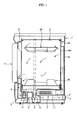
- FIG. 1 is a sectional view schematically illustrating a clothes drying apparatus according to an embodiment of the present invention.
- the clothes drying apparatus includes: a housing 1 having an approximately box shape to define an appearance of the clothes drying apparatus; a rotating drum 2 installed in the housing 1 and adapted to receive clothes to be dried; a driving unit 3 rotating the rotating drum 2 to rapidly dry the clothes, and intake and exhaust ducts 7 and 8 circulating ambient air through the rotating drum 2.
- the rotating drum 2 is opened at front and rear ends thereof.
- Front and rear panels 9 and 10 are mounted to the front and rear ends of the rotating drum 2, respectively, to close the rotating drum 2 while allowing the rotating drum 2 to rotate with respect therewith.
- the driving unit 3 includes a drive motor 4 generating a rotating force, a pulley 5 coupled to a rotating shaft of the drive motor 4, and a belt 6 wound on an outer peripheral surface of the rotating drum 2 and the pulley 5.
- the intake duct 7 is opened at its inlet portion while being connected, at its outlet portion, to the rear panel 10.
- a heater 11 is arranged in the intake duct 7 to heat air introduced into the intake duct 7.
- intake holes are positioned at a rear wall plate 1a of the housing 1.
- Through holes 10a are also positioned at the rear panel 10 to introduce hot air from the intake duct 7 into the rotating drum 2.
- the exhaust duct 8 is connected, at its inlet portion, to the front panel 9 while being opened at its outlet portion.
- the outlet portion of the exhaust duct 8 extends externally beyond the housing 1. Accordingly, ambient air around the housing 1 can be introduced into the rotating drum 2 via the intake duct 7, and then forcibly vented out of the housing 1 via the exhaust duct 8.
- a door 13 is hingably coupled to a front wall of the housing 1, so that clothes to be driedmay be placed in the rotating drum 2 through an opening of the front panel 9, and dried clothes may be removed from the rotating drum 2.
- a plurality of lifters 20 are arranged on the inner peripheral surface of the rotating drum 2 while being uniformly circumferentially spaced apart from one another.
- the lifters 20 serve to raise the clothes to the top of the rotating drum 2, and then release the clothes at a desired level to cause the clothes to be dropped to the bottom of the rotating drum 2, in accordance with rotation of the rotating drum, to cause the clothes to be uniformly dried.
- FIG. 2 is a perspective view illustrating the lifters 20 of FIG. 1.
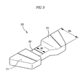
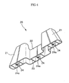
- FIGS. 3 and 4 are front and rear perspective views of one of the lifters 20, respectively.
- the rotating drum 2 is opened at its front and rear ends.
- the rotating drum 2 is rotated at low speed in one direction (indicated by an arrow in FIG. 2) by the belt 6 (FIG. 1).
- the lifters 20 are arranged on the inner peripheral surface of the rotating drum 2 such that they are uniformly circumferentially spaced apart from one another, while extending axially along the rotating drum 2.
- the clothes contained in the rotating drum 2 are raised from the bottom of the rotating drum 2 by the lifters 20, and then released from the lifters 20 at the top of the rotating drum 2, so that they are dropped onto the bottom of the rotating drum 2.
- the clothes can come into uniform contact with hot air passing through the rotating drum 2, so that they can be rapidly and uniformly dried.
- each lifter 20 has a stepped structure to prevent the clothes from remaining attached to the surface of the lifter 20 without being released from the lifter 20 at the top of the rotating drum 2. That is, the lifter 20 has step surfaces of different levels.
- the lifter 20 has a pair of first step surfaces 21 arranged at front and rear end portions of the lifter 20 while being flush with each other, and a second step surface 22 arranged between the first step surfaces 21 at a level lower than that of the first step surfaces 21.
- the lifter 20 which is adapted to raise clothes contained in the rotating drum 2, has a stepped structure at its surface.
- the second step surface 22 arranged at a lower level has a width W1 smaller than a width W2 of the first step surfaces 21 arranged at a higher level.
- additional first and second step surfaces 21 and 22 are arranged on the lifter 20, such that the first step surfaces 21 are arranged at a level higher than those of the step surfaces 22.
- the lifter 20 has, at its upper surface contacting the clothes to raise it, higher-level portions defined by respective first step surfaces 21, and a lower-level portion defined by the second step surface 22.
- the second step surface 22 is arranged at a level higher than that of the first step surfaces 21, while being interposed between the first step surfaces 21.
- the lifter 20 has a stepped structure in which the intermediate portion of the lifter 20 is arranged at a level higher than that of the front and rear end portions of the lifter 20.
- additional first and second step surfaces 21 and 22 are arranged on the lifter 20, such that the second step surfaces 22 are arranged at levels higher than those of the first step surfaces 21.
- clothes or laundry L (FIG. 2), which is arranged just over the lifter 20, is raised by the lifter 20 without coming into contact with the upper surface portion of the lifter 20 corresponding to the second step surface 22, so that it can be easily released from the lifter 20 when the lifter 20 is moved to the top of the rotating drum 2.
- the lifter 20 is opened at a fixing end thereof to fix the lifter 20 in a state of being in contact with the inner peripheral surface of the rotating drum 2.
- a plurality of ribs 23 and bosses 24 are provided at the lifter 20 such that they extend from the opened fixing end of the lifter 20 into an interior of the lifter 20.
- Each boss 24 has a threaded coupling hole 24a, to which a screw 25 (FIG. 2) will be threadedly coupled at the outside of the rotating drum 2, in order to fix the lifter 20 to the inner peripheral surface of the rotating drum 2.
- the lifters 20 are integrally formed with the rotating drum 2.
- the user puts the clothes to be dried into the rotating drum 2, and then closes the door 13.
- the rotating drum 2 is rotated at low speed in the direction indicated by the arrow in FIG. 2.
- ambient air around the housing 1 is introduced into the intake duct 7.
- the clothes are sequentially upwardly raised from the bottom of the rotating drum by the lifters 20, and then dropped from the top of the rotating drum 2 onto the bottom thereof.
- the air introduced into the intake duct 7 is heated by the heater 11, and then fed to the rotating drum 2 through the through holes 10a of the rear panel 10.
- the hot air introduced into the rotating drum 2 rapidly and uniformly dries the clothes periodically tumbled by the lifters 20, while passing through the rotating drum 2.
- the clothes are upwardly raised from the bottom of the rotating drum 2 by the lifters 20 in a sequential fashion without coming into contact with the second step surface 22 of each lifter 20. Accordingly, the clothes are easily released from the lifters 20 when each lifter 20 reaches a certain level, so that they are dropped onto the bottom of the rotating drum 2.
- the air which has increased humidity due to its absorption of humidity from the clothes coming into contact therewith, is vented out of the housing 1 through the exhaust duct 8. Simultaneously, fresh air is introduced into the intake duct 7, heated while passing through the intake duct 7, and is then introduced into the rotating drum 2. As this process is repeatedly carried out, the clothes are completely dried.
- the clothes drying apparatus uniformly dries clothes while achieving a reduction in drying time because its lifters have a stepped structure that allows the clothes to be easily released from the surface of each lifter. Accordingly, there is an enhancement in drying performance.
Abstract
Description
- The present invention relates to clothes drying apparatus, and more particularly, but not exclusively, to clothes drying apparatus in which lifters, arranged on an inner peripheral surface of a rotating drum while extending axially along the rotating drum, have an improved structure to achieve an enhancement in drying performance.
- Generally, clothes drying machines are adapted to dry clothes contained in a rotating drum, horizontally arranged in a housing, by a flow of hot air passing through the rotating drum during rotation of the rotating drum at low speed in one direction.
- Such a clothes drying machine includes a rotating drum receiving clothes to be dried, an intake duct supplying hot air into the rotating drum, an exhaust duct venting the hot air exhausted after circulating the rotating drum, and a driving unit rotating the rotating drum to rapidly dry the clothes.
- A heater is installed in the intake duct to increase the temperature of the air introduced into the intake duct. An exhaust fan is installed in the exhaust duct to forcibly vent hot air introduced into the rotating drum through the intake duct.
- The driving unit includes a drive motor generating a rotating force, and a belt connected to a rotating shaft of the drive motor while being wound on an outer peripheral surface of the rotating drum. When the drive motor operates, the belt is rotated, thereby rotating the rotating drum.
- A plurality of lifters are arranged on an inner peripheral surface of the rotating drum while extending axially along the rotating drum. To more rapidly and effectively dry clothes contained in the rotating drum, the lifters raise the clothes to the top of the rotating drum, and then release the clothes to cause the clothes to be dropped to the bottom of the rotating drum, in accordance with the rotation of the rotating drum.
- In the clothes drying machine having the above mentioned configuration, as the drive motor, exhaust fan, and heater operate, the rotating drum is rotated at low speed, and hot air is introduced into the rotating drum through the intake duct. Accordingly, the clothes contained the rotating drum come into contact with the introduced hot air while being downwardly dropped by the lifters, so that they are dried. The air, which has increased humidity due to its absorption of humidity from the clothes coming into contact therewith, is forcibly vented from the clothes drying machine through the exhaust duct.
- In this clothes drying machine, however, the clothes may be continuously rotated in a state of being held on the lifters during rotation of the rotating drum, without being dropped after being raised to the top of the rotating drum by the lifters in accordance with the rotation of the rotating drum, because each lifter has an axial structure, with respect to the rotating drum, throughout the length thereof. As a result, the clothes come into insufficient contact with hot air, so that they may be ineffectively dried. Furthermore, there is a drawback in that a prolonged drying operation is required.
- An aim of preferred embodiments of the present invention is to provide a clothes drying apparatus in which lifters arranged on the inner peripheral surface of a rotating drum, while extending axially along the rotating drum, have an improved structure to achieve an enhancement in drying performance.
- In accordance with the present invention, there is provided a clothes drying apparatus having: a rotating drum to contain clothes to be dried; and a plurality of lifters arranged on an inner peripheral surface of the rotating drum, wherein each lifter has a stepped structure causing the clothes to be easily released from the lifter after being raised by the lifter.
- Suitably, each lifter has at least one first step surface, and a second step surface, the first and second step surfaces being arranged at different levels to form the stepped structure.
- Suitably, the at least one first step surface is a pair of first step surfaces respectively arranged at opposite end portions of the lifter, and the second step surface is arranged between the first step surfaces at a level lower than that of the first step surfaces.
- Suitably, the at least one first step surface is a pair of first step surfaces respectively arranged at opposite end portions of the lifter, and the second step surface is arranged between the first step surfaces at a level higher than that of the first step surfaces.
- Further features of the present invention are set out in the appended claims.
- The present invention will become apparent and more readily appreciated from the following description of the embodiments by way of example only, taken in conjunction with the accompanying drawings, of which:
- FIG. 1 is a sectional view schematically illustrating a clothes drying apparatus according to an embodiment of the present invention;
- FIG. 2 is a perspective view illustrating lifters of FIG. 1;
- FIG. 3 is a front perspective view of one lifter of FIG. 1; and
- FIG. 4 is a rear perspective view of the lifter of FIG. 1.
-
- Reference will now be made in detail to embodiments of the present invention, examples of which are illustrated in the accompanying drawings, wherein like reference numerals refer to the like elements throughout. The embodiments are described below to explain the present invention by referring to the figures.
- FIG. 1 is a sectional view schematically illustrating a clothes drying apparatus according to an embodiment of the present invention. As is shown in FIG. 1, the clothes drying apparatus includes: a housing 1 having an approximately box shape to define an appearance of the clothes drying apparatus; a rotating
drum 2 installed in the housing 1 and adapted to receive clothes to be dried; adriving unit 3 rotating the rotatingdrum 2 to rapidly dry the clothes, and intake andexhaust ducts drum 2. - The rotating
drum 2 is opened at front and rear ends thereof. Front andrear panels drum 2, respectively, to close the rotatingdrum 2 while allowing the rotatingdrum 2 to rotate with respect therewith. - The driving
unit 3 includes adrive motor 4 generating a rotating force, apulley 5 coupled to a rotating shaft of thedrive motor 4, and abelt 6 wound on an outer peripheral surface of the rotatingdrum 2 and thepulley 5. With this structure, when thedrive motor 4 rotates at low speed, thebelt 6 is rotated along with thepulley 5, thereby causing the rotatingdrum 2 torotate. - The
intake duct 7 is opened at its inlet portion while being connected, at its outlet portion, to therear panel 10. Aheater 11 is arranged in theintake duct 7 to heat air introduced into theintake duct 7. - To introduce ambient air into the
intake duct 7, intake holes (not shown) are positioned at arear wall plate 1a of the housing 1. Throughholes 10a are also positioned at therear panel 10 to introduce hot air from theintake duct 7 into the rotatingdrum 2. - The
exhaust duct 8 is connected, at its inlet portion, to thefront panel 9 while being opened at its outlet portion. The outlet portion of theexhaust duct 8 extends externally beyond the housing 1. Accordingly, ambient air around the housing 1 can be introduced into the rotatingdrum 2 via theintake duct 7, and then forcibly vented out of the housing 1 via theexhaust duct 8. - A
door 13 is hingably coupled to a front wall of the housing 1, so that clothes to be driedmay be placed in the rotatingdrum 2 through an opening of thefront panel 9, and dried clothes may be removed from the rotatingdrum 2. - A plurality of
lifters 20 are arranged on the inner peripheral surface of the rotatingdrum 2 while being uniformly circumferentially spaced apart from one another. Thelifters 20 serve to raise the clothes to the top of the rotatingdrum 2, and then release the clothes at a desired level to cause the clothes to be dropped to the bottom of the rotatingdrum 2, in accordance with rotation of the rotating drum, to cause the clothes to be uniformly dried. - The structure of the lifters will now be described with reference to FIGS. 2 to 4.
- FIG. 2 is a perspective view illustrating the
lifters 20 of FIG. 1. FIGS. 3 and 4 are front and rear perspective views of one of thelifters 20, respectively. - Referring to FIG. 2, the
rotating drum 2 is opened at its front and rear ends. During a drying process, the rotatingdrum 2 is rotated at low speed in one direction (indicated by an arrow in FIG. 2) by the belt 6 (FIG. 1). As is shown in FIG. 2, thelifters 20 are arranged on the inner peripheral surface of the rotatingdrum 2 such that they are uniformly circumferentially spaced apart from one another, while extending axially along the rotatingdrum 2. - When the rotating
drum 2 rotates at low speed in the direction indicated by the arrow in FIG. 2, the clothes contained in the rotatingdrum 2 are raised from the bottom of the rotatingdrum 2 by thelifters 20, and then released from thelifters 20 at the top of the rotatingdrum 2, so that they are dropped onto the bottom of the rotatingdrum 2. Thus, the clothes can come into uniform contact with hot air passing through the rotatingdrum 2, so that they can be rapidly and uniformly dried. - As is shown in FIG. 3, each
lifter 20 has a stepped structure to prevent the clothes from remaining attached to the surface of thelifter 20 without being released from thelifter 20 at the top of the rotatingdrum 2. That is, thelifter 20 has step surfaces of different levels. - According to one embodiment, the
lifter 20 has a pair offirst step surfaces 21 arranged at front and rear end portions of thelifter 20 while being flush with each other, and asecond step surface 22 arranged between thefirst step surfaces 21 at a level lower than that of thefirst step surfaces 21. Thus, thelifter 20, which is adapted to raise clothes contained in the rotatingdrum 2, has a stepped structure at its surface. Thesecond step surface 22 arranged at a lower level has a width W1 smaller than a width W2 of thefirst step surfaces 21 arranged at a higher level. According to another embodiment (not shown), additional first andsecond step surfaces lifter 20, such that thefirst step surfaces 21 are arranged at a level higher than those of thestep surfaces 22. - Accordingly, the
lifter 20 has, at its upper surface contacting the clothes to raise it, higher-level portions defined by respectivefirst step surfaces 21, and a lower-level portion defined by thesecond step surface 22. According to another embodiment (not shown), thesecond step surface 22 is arranged at a level higher than that of thefirst step surfaces 21, while being interposed between thefirst step surfaces 21. In this case, thelifter 20 has a stepped structure in which the intermediate portion of thelifter 20 is arranged at a level higher than that of the front and rear end portions of thelifter 20. According to yet another embodiment (not shown), additional first andsecond step surfaces lifter 20, such that thesecond step surfaces 22 are arranged at levels higher than those of thefirst step surfaces 21. - With the above described stepped structure of the
lifter 20, clothes or laundry L (FIG. 2), which is arranged just over thelifter 20, is raised by thelifter 20 without coming into contact with the upper surface portion of thelifter 20 corresponding to thesecond step surface 22, so that it can be easily released from thelifter 20 when thelifter 20 is moved to the top of the rotatingdrum 2. - As is shown in FIG. 4, the
lifter 20 is opened at a fixing end thereof to fix thelifter 20 in a state of being in contact with the inner peripheral surface of the rotatingdrum 2. A plurality ofribs 23 andbosses 24 are provided at thelifter 20 such that they extend from the opened fixing end of thelifter 20 into an interior of thelifter 20. - Each
boss 24 has a threadedcoupling hole 24a, to which a screw 25 (FIG. 2) will be threadedly coupled at the outside of therotating drum 2, in order to fix thelifter 20 to the inner peripheral surface of therotating drum 2. - According to another embodiment (not shown), the
lifters 20 are integrally formed with therotating drum 2. - Now, the process of drying clothes by the clothes drying apparatus having the above described configuration according to the illustrated embodiment of the present invention will be described.
- First, the user puts the clothes to be dried into the
rotating drum 2, and then closes thedoor 13. When the user subsequently operates thedrive motor 4,exhaust fan 12, andheater 11, therotating drum 2 is rotated at low speed in the direction indicated by the arrow in FIG. 2. Simultaneously, ambient air around the housing 1 is introduced into theintake duct 7. - In accordance with the rotation of the
rotating drum 2, the clothes are sequentially upwardly raised from the bottom of the rotating drum by thelifters 20, and then dropped from the top of therotating drum 2 onto the bottom thereof. The air introduced into theintake duct 7 is heated by theheater 11, and then fed to therotating drum 2 through the throughholes 10a of therear panel 10. - Thus, the hot air introduced into the
rotating drum 2 rapidly and uniformly dries the clothes periodically tumbled by thelifters 20, while passing through therotating drum 2. - During this drying process, the clothes are upwardly raised from the bottom of the
rotating drum 2 by thelifters 20 in a sequential fashion without coming into contact with thesecond step surface 22 of eachlifter 20. Accordingly, the clothes are easily released from thelifters 20 when eachlifter 20 reaches a certain level, so that they are dropped onto the bottom of therotating drum 2. - Meanwhile, the air, which has increased humidity due to its absorption of humidity from the clothes coming into contact therewith, is vented out of the housing 1 through the
exhaust duct 8. Simultaneously, fresh air is introduced into theintake duct 7, heated while passing through theintake duct 7, and is then introduced into therotating drum 2. As this process is repeatedly carried out, the clothes are completely dried. - As is apparent from the above description, the clothes drying apparatus according to preferred embodiments of the present invention uniformly dries clothes while achieving a reduction in drying time because its lifters have a stepped structure that allows the clothes to be easily released from the surface of each lifter. Accordingly, there is an enhancement in drying performance.
- Although a few embodiments of the present invention have been shown and described, it would be appreciated by those skilled in the art that changes may be made in this embodiment without departing from the principles and spirit of the invention, the scope of which is defined in the claims and their equivalents.
- Attention is directed to all papers and documents which are filed concurrently with or previous to this specification in connection with this application and which are open to public inspection with this specification, and the contents of all such papers and documents are incorporated herein by reference.
- All of the features disclosed in this specification (including any accompanying claims, abstract and drawings), and/or all of the steps of any method or process so disclosed, may be combined in any combination, except combinations where at least some of such features and/or steps are mutually exclusive.
- Each feature disclosed in this specification (including any accompanying claims, abstract and drawings) may be replaced by alternative features serving the same, equivalent or similar purpose, unless expressly stated otherwise. Thus, unless expressly stated otherwise, each feature disclosed is one example only of a generic series of equivalent or similar features.
- The invention is not restricted to the details of the foregoing embodiment(s). The invention extends to any novel one, or any novel combination, of the features disclosed in this specification (including any accompanying claims, abstract and drawings), or to any novel one, or any novel combination, of the steps of any method or process so disclosed.
Claims (16)
- A clothes drying apparatus comprising:wherein each lifter (20) has a stepped structure causing the clothes to be easily released from the lifter (20) after being raised by the lifter (20).a rotating drum (2) to contain clothes to be dried; anda plurality of lifters (20) arranged on an inner peripheral surface of the rotating drum (2),
- The clothes drying apparatus according to claim 1, wherein each lifter (20) has at least one first step surface (21), and a second step surface (22), the first and second step surfaces (21, 22) being arranged at different levels to form the stepped structure.
- The clothes drying apparatus according to claim 2, wherein the at least one first step surface (21) comprises a pair of first step surfaces respectively arranged at opposite end portions of the lifter, and the second step surface is arranged between the first step surfaces at a level lower than that of the first step surfaces.
- The clothes drying apparatus according to claim 2, wherein the at least one first step surface (21) comprises a pair of first step surfaces (21) respectively arranged at opposite end portions of the lifter (20), and the second step surface (22) is arranged between the first step surfaces (21) at a level higher than that of the first step surfaces (21).
- A clothes drying apparatus including a rotating drum (2) to contain clothes to be dried, provided with a plurality of lifters (20) arranged on an inner peripheral surface thereof, wherein each lifter (20) has at least one higher-level surface portion (21) and at least one lower-level surface portion (22) at a surface thereof coming into contact with the clothes, to raise the clothes from a bottom of the rotating drum (2), whereby the clothes are easily dropped after being raised to a top of the rotating drum (2).
- The clothes drying apparatus according to claim 5, wherein the at least one higher-level surface portion (21) comprises a pair of higher-level surface portions (21) respectively arranged at opposite end surfaces of the lifter (20), and the at least one lower-level surface portion (22) comprises a lower-level surface portion (22) arranged between the higher-level surface portions (21).
- The clothes drying apparatus according to claim 5, wherein the at least one lower-level surface portion (22) comprises a pair of lower-level surface portions (22) respectively arranged at opposite end surfaces of the lifter (20), and the at least one higher-level surface portion (21) comprises a higher-level surface portion (21) arranged between the lower-level surface portions (22).
- The clothes drying apparatus according to any one of claims 5-7, wherein the at least one lower-level surface portion (22) has a radial width smaller than that of the at least one upper-level surface portion (21).
- A clothes drying apparatus including a housing (1), the clothes drying apparatus comprising:a drum (2) rotatably disposed in the housing (1); anda lifter (20) protruding from an inner circumferential surface of the drum (2) and having first (21) and second (22) leading surfaces, the first leading surface (21) passing a fixed point on the housing (1) prior to the second leading surface (22) during rotation of the drum (2).
- The clothes drying apparatus according to claim 9, wherein the first leading surface (21) protrudes farther from the inner circumferential surface of the drum (2) than the second leading surface (22).
- The clothes drying apparatus according to claim 9, wherein the second leading surface (22) protrudes farther from the inner circumferential surface of the drum (2) than the first leading surface (21).
- The clothes drying apparatus according to any one of claims 9-11, wherein the first leading surface (21) comprises a pair of first leading surfaces (21) axially disposed on opposite ends of the second leading surface (22).
- The clothes drying apparatus according to any one of claims 9-11, wherein the second leading surface (22) comprises a pair of second leading surfaces (22) axially disposed on opposite ends of the first leading surface (21).
- The clothes drying apparatus according to any one of claims 9-13, wherein an internal structure of the lifter (20) comprises:a rib (23); anda boss (24), the boss (24) having a threaded coupling hole (24a) via which the lifter (20) is attached to the drum (2).
- The clothes drying apparatus according to any one of claims 9-14, wherein the lifter (20) and the drum (2) are integrally formed.
- A clothes drying apparatus including a housing (1), the clothes drying apparatus comprising:a drum (2) rotatably disposed about an axis within the housing (1); anda lifter (20) protruding from an inner circumferential surface of the drum (2) toward the axis, and having a stepped surface with respect to a direction of rotation of the drum (2).
Applications Claiming Priority (2)
| Application Number | Priority Date | Filing Date | Title |
|---|---|---|---|
| KR2003081243 | 2003-11-17 | ||
| KR1020030081243A KR101073508B1 (en) | 2003-11-17 | 2003-11-17 | Clothes Drying Apparatus |
Publications (3)
| Publication Number | Publication Date |
|---|---|
| EP1533414A2 true EP1533414A2 (en) | 2005-05-25 |
| EP1533414A3 EP1533414A3 (en) | 2006-10-04 |
| EP1533414B1 EP1533414B1 (en) | 2016-10-05 |
Family
ID=34431784
Family Applications (1)
| Application Number | Title | Priority Date | Filing Date |
|---|---|---|---|
| EP04018418.6A Active EP1533414B1 (en) | 2003-11-17 | 2004-08-04 | Clothes drying apparatus |
Country Status (5)
| Country | Link |
|---|---|
| US (1) | US7194824B2 (en) |
| EP (1) | EP1533414B1 (en) |
| JP (1) | JP2005144151A (en) |
| KR (1) | KR101073508B1 (en) |
| CN (1) | CN1619048A (en) |
Cited By (4)
| Publication number | Priority date | Publication date | Assignee | Title |
|---|---|---|---|---|
| EP2309048A1 (en) * | 2009-10-06 | 2011-04-13 | Miele & Cie. KG | Drum for a washing machine |
| EP2339060A2 (en) * | 2008-08-28 | 2011-06-29 | Daewoo Electronics Corporation | Dryer with a hybrid lifter |
| US8042282B2 (en) | 2006-02-27 | 2011-10-25 | Lg Electronics Inc. | Drum for clothes dryer |
| CN101089277B (en) * | 2006-06-15 | 2011-12-21 | Lg电子株式会社 | Washer and method of forming drum thereof |
Families Citing this family (21)
| Publication number | Priority date | Publication date | Assignee | Title |
|---|---|---|---|---|
| US7627960B2 (en) * | 2003-06-30 | 2009-12-08 | General Electric Company | Clothes dryer drum projections |
| KR101093878B1 (en) * | 2004-06-05 | 2011-12-13 | 엘지전자 주식회사 | A drum apparatus of a dryer |
| DE102004055942A1 (en) * | 2004-11-19 | 2006-05-24 | BSH Bosch und Siemens Hausgeräte GmbH | clothes dryer |
| DE102006023389A1 (en) * | 2006-05-17 | 2007-11-22 | Herbert Kannegiesser Gmbh | Method and device for treating, preferably washing, spinning and / or drying, laundry |
| KR100722548B1 (en) * | 2006-07-13 | 2007-05-29 | 김진문 | Dryer |
| CA2554497C (en) * | 2006-07-28 | 2010-02-16 | Mabe Canada Inc. | Blower wheel attachment for clothes dryer |
| US8872074B2 (en) * | 2007-09-11 | 2014-10-28 | General Electric Company | Centrifugal switch bypass for reverse tumble dryers |
| KR101308510B1 (en) * | 2007-11-05 | 2013-09-12 | 동부대우전자 주식회사 | Dryer having indrawn tube with heater |
| KR101256145B1 (en) * | 2007-11-05 | 2013-04-23 | 동부대우전자 주식회사 | Dryer having indrawn tube with heater |
| US8065816B2 (en) * | 2007-12-03 | 2011-11-29 | Electrolux Home Products, Inc. | Dryer drum vane |
| US8234797B2 (en) | 2008-06-30 | 2012-08-07 | Electrolux Home Products, Inc. | Dryer drum vane and vane set |
| US20100132219A1 (en) * | 2008-11-30 | 2010-06-03 | Soheil Etemad | Dryer with reverse tumble action |
| US20100132218A1 (en) * | 2008-11-30 | 2010-06-03 | Soheil Etemad | Dryer with stationary drying cycle |
| EP2815014B1 (en) | 2012-02-16 | 2017-09-06 | LG Electronics Inc. | Laundry treating apparatus |
| KR102017530B1 (en) * | 2012-11-22 | 2019-09-04 | 삼성전자주식회사 | Lifter and drying machine having the same |
| US9458563B2 (en) * | 2013-06-12 | 2016-10-04 | Alliance Laundry Systems Llc | Front loading washer baffle |
| JPWO2015159548A1 (en) * | 2014-04-18 | 2017-04-13 | Necソリューションイノベータ株式会社 | Projection control apparatus, projection control method, and projection control program |
| CN109208247A (en) * | 2017-07-07 | 2019-01-15 | 青岛海尔滚筒洗衣机有限公司 | The water extraction leaf and washing machine of washing machine |
| WO2020032886A2 (en) * | 2018-08-06 | 2020-02-13 | Arcelik Anonim Sirketi | A washer/dryer with improved washing performance |
| USD901111S1 (en) * | 2018-12-03 | 2020-11-03 | Samsung Electronics Co., Ltd. | Lifter for washing machine |
| US20220251761A1 (en) * | 2021-02-08 | 2022-08-11 | Lg Electronics Inc. | Laundry treating apparatus |
Citations (6)
| Publication number | Priority date | Publication date | Assignee | Title |
|---|---|---|---|---|
| JPH03280998A (en) * | 1990-03-30 | 1991-12-11 | Hitachi Ltd | Clothes drying machine |
| DE4021533A1 (en) * | 1990-07-06 | 1992-01-09 | Bauknecht Hausgeraete | Dryer incorporates horizontal revolving cylindrical drum - at least one drum end features projection extending into drum |
| JPH04152990A (en) * | 1990-10-16 | 1992-05-26 | Matsushita Electric Ind Co Ltd | Drum type clothes drier |
| EP1270794A1 (en) * | 2001-06-29 | 2003-01-02 | Lg Electronics Inc. | Drum for clothes drier |
| EP1350880A1 (en) * | 2002-04-06 | 2003-10-08 | Electrolux Home Products Corporation N.V. | Washing machine and method for washing laundry in a washing machine |
| DE10227957A1 (en) * | 2002-06-22 | 2004-01-08 | Electrolux Home Products Corporation N.V. | Horizontal axis washing machine clothes drum has two part lifters axially separated at slightly different radial positions to increase tumbling effect |
Family Cites Families (16)
| Publication number | Priority date | Publication date | Assignee | Title |
|---|---|---|---|---|
| US857161A (en) * | 1907-02-15 | 1907-06-18 | William M Cummer | Mechanical drier. |
| US3017758A (en) * | 1957-08-12 | 1962-01-23 | Philco Corp | Laundering machines |
| US3038639A (en) | 1957-10-31 | 1962-06-12 | American Radiator & Standard | Pressure actuated dispenser for washing machines |
| US3022656A (en) | 1959-08-28 | 1962-02-27 | Maytag Co | Dispenser for laundry machines |
| DE1916916C3 (en) * | 1969-04-02 | 1975-08-14 | Hans F. Arendt, Maschinenbau, 7120 Bietigheim | Drum dryer for drying hides, furs, soft leather or the like |
| US3815258A (en) * | 1972-11-30 | 1974-06-11 | Whirlpool Co | Dryer having drum with two different diameters |
| ES238080Y (en) | 1978-09-09 | 1979-05-01 | PERFECTED WASHER DOOR WITH DRAWER CARRIER FOR DETERGENT. | |
| JPS55167387U (en) * | 1979-05-17 | 1980-12-02 | ||
| US4519145A (en) * | 1984-03-12 | 1985-05-28 | Magic Chef, Inc. | Electrostatic and moisture control system for automatic clothes dryers |
| CA2062016C (en) * | 1992-02-27 | 1999-07-27 | Robert Maurice St. Louis | Snap-in baffle for clothes dryer |
| IT1272065B (en) | 1993-11-30 | 1997-06-11 | Merloni Elettrodomestici Spa | FRONT-LOADING WASHING MACHINE. |
| KR200151035Y1 (en) * | 1994-12-07 | 1999-07-15 | 윤종용 | Vibration and noise decreasing device of drum washer |
| US5463821A (en) * | 1995-01-03 | 1995-11-07 | Whirlpool Corporation | Method and apparatus for operating a microwave dryer |
| US5782111A (en) * | 1996-07-02 | 1998-07-21 | Sights Denim Systems Inc | Mechanical desizing and abrading apparatus |
| KR100388702B1 (en) | 2000-07-15 | 2003-06-25 | 삼성전자주식회사 | A attachment structure for lifter of dryer |
| ITTO20030066A1 (en) | 2003-02-04 | 2004-08-05 | Merloni Elettrodomestici Spa | WASHING MACHINE, IN PARTICULAR LOADING |
-
2003
- 2003-11-17 KR KR1020030081243A patent/KR101073508B1/en active IP Right Grant
-
2004
- 2004-07-23 US US10/897,010 patent/US7194824B2/en active Active
- 2004-08-04 EP EP04018418.6A patent/EP1533414B1/en active Active
- 2004-08-20 CN CNA200410056917XA patent/CN1619048A/en active Pending
- 2004-09-28 JP JP2004282625A patent/JP2005144151A/en active Pending
Patent Citations (6)
| Publication number | Priority date | Publication date | Assignee | Title |
|---|---|---|---|---|
| JPH03280998A (en) * | 1990-03-30 | 1991-12-11 | Hitachi Ltd | Clothes drying machine |
| DE4021533A1 (en) * | 1990-07-06 | 1992-01-09 | Bauknecht Hausgeraete | Dryer incorporates horizontal revolving cylindrical drum - at least one drum end features projection extending into drum |
| JPH04152990A (en) * | 1990-10-16 | 1992-05-26 | Matsushita Electric Ind Co Ltd | Drum type clothes drier |
| EP1270794A1 (en) * | 2001-06-29 | 2003-01-02 | Lg Electronics Inc. | Drum for clothes drier |
| EP1350880A1 (en) * | 2002-04-06 | 2003-10-08 | Electrolux Home Products Corporation N.V. | Washing machine and method for washing laundry in a washing machine |
| DE10227957A1 (en) * | 2002-06-22 | 2004-01-08 | Electrolux Home Products Corporation N.V. | Horizontal axis washing machine clothes drum has two part lifters axially separated at slightly different radial positions to increase tumbling effect |
Non-Patent Citations (2)
| Title |
|---|
| PATENT ABSTRACTS OF JAPAN vol. 016, no. 106 (C-0919), 16 March 1992 (1992-03-16) & JP 03 280998 A (HITACHI LTD), 11 December 1991 (1991-12-11) * |
| PATENT ABSTRACTS OF JAPAN vol. 016, no. 437 (C-0984), 11 September 1992 (1992-09-11) & JP 04 152990 A (MATSUSHITA ELECTRIC IND CO LTD), 26 May 1992 (1992-05-26) * |
Cited By (6)
| Publication number | Priority date | Publication date | Assignee | Title |
|---|---|---|---|---|
| US8042282B2 (en) | 2006-02-27 | 2011-10-25 | Lg Electronics Inc. | Drum for clothes dryer |
| DE102007009290B4 (en) * | 2006-02-27 | 2011-12-08 | Lg Electronics Inc. | Drum for a tumble dryer |
| CN101089277B (en) * | 2006-06-15 | 2011-12-21 | Lg电子株式会社 | Washer and method of forming drum thereof |
| EP2339060A2 (en) * | 2008-08-28 | 2011-06-29 | Daewoo Electronics Corporation | Dryer with a hybrid lifter |
| EP2339060A4 (en) * | 2008-08-28 | 2013-03-13 | Daewoo Electronics Corp | Dryer with a hybrid lifter |
| EP2309048A1 (en) * | 2009-10-06 | 2011-04-13 | Miele & Cie. KG | Drum for a washing machine |
Also Published As
| Publication number | Publication date |
|---|---|
| EP1533414B1 (en) | 2016-10-05 |
| EP1533414A3 (en) | 2006-10-04 |
| CN1619048A (en) | 2005-05-25 |
| US7194824B2 (en) | 2007-03-27 |
| JP2005144151A (en) | 2005-06-09 |
| US20050102853A1 (en) | 2005-05-19 |
| KR20050047421A (en) | 2005-05-20 |
| KR101073508B1 (en) | 2011-10-17 |
Similar Documents
| Publication | Publication Date | Title |
|---|---|---|
| EP1533414A2 (en) | Clothes drying apparatus | |
| EP2175064B1 (en) | Clothing dryer | |
| US8266816B2 (en) | Clothes dryer and door thereof | |
| RU69524U1 (en) | WASHING MACHINE OF DRUM TYPE (OPTIONS) AND DRYING DEVICE FOR SUCH WASHING MACHINE | |
| KR20060097239A (en) | A clothes dryer and a method for removing lint thereof | |
| EP1557488A1 (en) | Clothing dryer | |
| US7140123B2 (en) | Roller and clothes drying apparatus provided with the same | |
| TW202237935A (en) | Laundry treatment apparatus | |
| KR100619728B1 (en) | Apparatus for sealing drum in clothing dryer | |
| CA2506502C (en) | Laundry dryer with novel exhaust pipe installation structure | |
| US20050155250A1 (en) | Clothes drying apparatus | |
| EP2759634B1 (en) | Washing and drying machine | |
| KR100610664B1 (en) | Clothes Drying Apparatus | |
| KR100421379B1 (en) | Clothes dryer | |
| US3963370A (en) | Laundry machine blower mechanism | |
| KR100570529B1 (en) | Clothes Drying Apparatus | |
| KR101034195B1 (en) | Clothes Drying Apparatus | |
| KR100585323B1 (en) | Clothes Drying Apparatus | |
| KR100465725B1 (en) | A dryer | |
| KR101071834B1 (en) | structure of roller for clothing dryer | |
| JP2685276B2 (en) | Drum type washer / dryer | |
| JPS608876Y2 (en) | Dryer | |
| JPH0647193A (en) | Drum type washing/drying machine | |
| KR100465717B1 (en) | A dryer | |
| JPH0975596A (en) | Clothes drying machine exclusively for finish drying |
Legal Events
| Date | Code | Title | Description |
|---|---|---|---|
| PUAI | Public reference made under article 153(3) epc to a published international application that has entered the european phase |
Free format text: ORIGINAL CODE: 0009012 |
|
| AK | Designated contracting states |
Kind code of ref document: A2 Designated state(s): AT BE BG CH CY CZ DE DK EE ES FI FR GB GR HU IE IT LI LU MC NL PL PT RO SE SI SK TR |
|
| AX | Request for extension of the european patent |
Extension state: AL HR LT LV MK |
|
| PUAL | Search report despatched |
Free format text: ORIGINAL CODE: 0009013 |
|
| AK | Designated contracting states |
Kind code of ref document: A3 Designated state(s): AT BE BG CH CY CZ DE DK EE ES FI FR GB GR HU IE IT LI LU MC NL PL PT RO SE SI SK TR |
|
| AX | Request for extension of the european patent |
Extension state: AL HR LT LV MK |
|
| 17P | Request for examination filed |
Effective date: 20070305 |
|
| 17Q | First examination report despatched |
Effective date: 20070403 |
|
| AKX | Designation fees paid |
Designated state(s): DE FR GB IT SE |
|
| RAP1 | Party data changed (applicant data changed or rights of an application transferred) |
Owner name: SAMSUNG ELECTRONICS CO., LTD. |
|
| GRAP | Despatch of communication of intention to grant a patent |
Free format text: ORIGINAL CODE: EPIDOSNIGR1 |
|
| INTG | Intention to grant announced |
Effective date: 20160719 |
|
| GRAS | Grant fee paid |
Free format text: ORIGINAL CODE: EPIDOSNIGR3 |
|
| GRAA | (expected) grant |
Free format text: ORIGINAL CODE: 0009210 |
|
| AK | Designated contracting states |
Kind code of ref document: B1 Designated state(s): DE FR GB IT SE |
|
| REG | Reference to a national code |
Ref country code: GB Ref legal event code: FG4D |
|
| REG | Reference to a national code |
Ref country code: DE Ref legal event code: R096 Ref document number: 602004050045 Country of ref document: DE |
|
| PG25 | Lapsed in a contracting state [announced via postgrant information from national office to epo] |
Ref country code: SE Free format text: LAPSE BECAUSE OF FAILURE TO SUBMIT A TRANSLATION OF THE DESCRIPTION OR TO PAY THE FEE WITHIN THE PRESCRIBED TIME-LIMIT Effective date: 20161005 |
|
| REG | Reference to a national code |
Ref country code: DE Ref legal event code: R097 Ref document number: 602004050045 Country of ref document: DE |
|
| PLBE | No opposition filed within time limit |
Free format text: ORIGINAL CODE: 0009261 |
|
| STAA | Information on the status of an ep patent application or granted ep patent |
Free format text: STATUS: NO OPPOSITION FILED WITHIN TIME LIMIT |
|
| PG25 | Lapsed in a contracting state [announced via postgrant information from national office to epo] |
Ref country code: IT Free format text: LAPSE BECAUSE OF FAILURE TO SUBMIT A TRANSLATION OF THE DESCRIPTION OR TO PAY THE FEE WITHIN THE PRESCRIBED TIME-LIMIT Effective date: 20161005 |
|
| 26N | No opposition filed |
Effective date: 20170706 |
|
| GBPC | Gb: european patent ceased through non-payment of renewal fee |
Effective date: 20170804 |
|
| REG | Reference to a national code |
Ref country code: FR Ref legal event code: ST Effective date: 20180430 |
|
| REG | Reference to a national code |
Ref country code: GB Ref legal event code: S28 Free format text: APPLICATION FILED |
|
| REG | Reference to a national code |
Ref country code: GB Ref legal event code: S28 Free format text: RESTORATION ALLOWED Effective date: 20180626 |
|
| PG25 | Lapsed in a contracting state [announced via postgrant information from national office to epo] |
Ref country code: GB Free format text: LAPSE BECAUSE OF NON-PAYMENT OF DUE FEES Effective date: 20170804 |
|
| PG25 | Lapsed in a contracting state [announced via postgrant information from national office to epo] |
Ref country code: FR Free format text: LAPSE BECAUSE OF NON-PAYMENT OF DUE FEES Effective date: 20170831 |
|
| PGFP | Annual fee paid to national office [announced via postgrant information from national office to epo] |
Ref country code: GB Payment date: 20180725 Year of fee payment: 15 |
|
| GBPC | Gb: european patent ceased through non-payment of renewal fee |
Effective date: 20190804 |
|
| PG25 | Lapsed in a contracting state [announced via postgrant information from national office to epo] |
Ref country code: GB Free format text: LAPSE BECAUSE OF NON-PAYMENT OF DUE FEES Effective date: 20190804 |
|
| PGFP | Annual fee paid to national office [announced via postgrant information from national office to epo] |
Ref country code: DE Payment date: 20230720 Year of fee payment: 20 |