EP1533211B1 - Steering device for an industrial truck - Google Patents
Steering device for an industrial truck Download PDFInfo
- Publication number
- EP1533211B1 EP1533211B1 EP04025710A EP04025710A EP1533211B1 EP 1533211 B1 EP1533211 B1 EP 1533211B1 EP 04025710 A EP04025710 A EP 04025710A EP 04025710 A EP04025710 A EP 04025710A EP 1533211 B1 EP1533211 B1 EP 1533211B1
- Authority
- EP
- European Patent Office
- Prior art keywords
- steering
- brake
- steering angle
- freewheel
- rotation
- Prior art date
- Legal status (The legal status is an assumption and is not a legal conclusion. Google has not performed a legal analysis and makes no representation as to the accuracy of the status listed.)
- Active
Links
Images

Classifications
-
- B—PERFORMING OPERATIONS; TRANSPORTING
- B62—LAND VEHICLES FOR TRAVELLING OTHERWISE THAN ON RAILS
- B62D—MOTOR VEHICLES; TRAILERS
- B62D5/00—Power-assisted or power-driven steering
- B62D5/001—Mechanical components or aspects of steer-by-wire systems, not otherwise provided for in this maingroup
- B62D5/005—Mechanical components or aspects of steer-by-wire systems, not otherwise provided for in this maingroup means for generating torque on steering wheel or input member, e.g. feedback
- B62D5/006—Mechanical components or aspects of steer-by-wire systems, not otherwise provided for in this maingroup means for generating torque on steering wheel or input member, e.g. feedback power actuated
-
- B—PERFORMING OPERATIONS; TRANSPORTING
- B62—LAND VEHICLES FOR TRAVELLING OTHERWISE THAN ON RAILS
- B62D—MOTOR VEHICLES; TRAILERS
- B62D5/00—Power-assisted or power-driven steering
- B62D5/001—Mechanical components or aspects of steer-by-wire systems, not otherwise provided for in this maingroup
- B62D5/005—Mechanical components or aspects of steer-by-wire systems, not otherwise provided for in this maingroup means for generating torque on steering wheel or input member, e.g. feedback
-
- B—PERFORMING OPERATIONS; TRANSPORTING
- B62—LAND VEHICLES FOR TRAVELLING OTHERWISE THAN ON RAILS
- B62D—MOTOR VEHICLES; TRAILERS
- B62D5/00—Power-assisted or power-driven steering
- B62D5/04—Power-assisted or power-driven steering electrical, e.g. using an electric servo-motor connected to, or forming part of, the steering gear
- B62D5/0457—Power-assisted or power-driven steering electrical, e.g. using an electric servo-motor connected to, or forming part of, the steering gear characterised by control features of the drive means as such
- B62D5/046—Controlling the motor
- B62D5/0469—End-of-stroke control
-
- B—PERFORMING OPERATIONS; TRANSPORTING
- B62—LAND VEHICLES FOR TRAVELLING OTHERWISE THAN ON RAILS
- B62D—MOTOR VEHICLES; TRAILERS
- B62D6/00—Arrangements for automatically controlling steering depending on driving conditions sensed and responded to, e.g. control circuits
-
- B—PERFORMING OPERATIONS; TRANSPORTING
- B66—HOISTING; LIFTING; HAULING
- B66F—HOISTING, LIFTING, HAULING OR PUSHING, NOT OTHERWISE PROVIDED FOR, e.g. DEVICES WHICH APPLY A LIFTING OR PUSHING FORCE DIRECTLY TO THE SURFACE OF A LOAD
- B66F9/00—Devices for lifting or lowering bulky or heavy goods for loading or unloading purposes
- B66F9/06—Devices for lifting or lowering bulky or heavy goods for loading or unloading purposes movable, with their loads, on wheels or the like, e.g. fork-lift trucks
- B66F9/075—Constructional features or details
- B66F9/07509—Braking
-
- B—PERFORMING OPERATIONS; TRANSPORTING
- B66—HOISTING; LIFTING; HAULING
- B66F—HOISTING, LIFTING, HAULING OR PUSHING, NOT OTHERWISE PROVIDED FOR, e.g. DEVICES WHICH APPLY A LIFTING OR PUSHING FORCE DIRECTLY TO THE SURFACE OF A LOAD
- B66F9/00—Devices for lifting or lowering bulky or heavy goods for loading or unloading purposes
- B66F9/06—Devices for lifting or lowering bulky or heavy goods for loading or unloading purposes movable, with their loads, on wheels or the like, e.g. fork-lift trucks
- B66F9/075—Constructional features or details
- B66F9/07568—Steering arrangements
Definitions
- the invention relates to a steering device for a truck according to the preambles of claims 1, 4 and 7.
- steering devices there is no mechanical connection between the usually executed as a steering wheel steering member and the upstanding on the roadway steerable wheel.
- the rotational position of the steering element is detected with the steering sensor, which is designed, for example, as an angle sensor, and generates a dependent electrical signal, which is then supplied to the electrical control device.
- This control device evaluates the electrical signal and then controls the electric steering motor, which causes a steering movement of the steerable wheel.
- the actual steering angle of the steerable wheel is detected by the steering angle sensor and also supplied to the control device.
- Such steering devices are commonly referred to as electric steering devices or "steer-by-wire" steering devices.
- the steering forces acting on the steerable wheel are not transmitted to the steering member in generic steering devices due to the lack of mechanical connection.
- the invention is therefore an object of the invention to provide a steering device of the type mentioned above, which is simple and in which a reaching the maximum steering angle in a comparable manner on the steering member is noticeable, as in a mechanical steering.
- the control device detects by a corresponding signal of the steering angle sensor that the steerable wheel has reached its maximum steering angle. Then, the braking device is activated by the control device such that a further rotation of the steering member in the direction of a further increase in the steering angle counteracts a braking torque. A turning back of the steering member in the opposite direction, however, is possible without hindrance. The operator thus receives the impression that the steering element has reached a stop which prevents further rotation of the steering element in a first direction, but allows the steering element to be turned back without resistance.
- the control device is designed such that the braking device is activated when the steering angle sensor detects that the steering angle of the steerable wheel corresponds to the maximum steering angle, the braking device for the direction of rotation of the steering member, which corresponds to an increase of the steering angle is effective, and for the other direction of rotation of the steering member, which corresponds to a reduction in the steering angle, is not effective.
- the brake device comprises at least one brake element, which has a non-rotatable brake housing and a brake body rotatably mounted relative to the brake housing, wherein a rotational movement of the brake body can be braked by operating the brake element.
- the brake housing for example, rigidly attached to a frame of the truck.
- the brake body is directly or indirectly with the steering member or with a steering member associated steering shaft, so that a rotational movement of the steering member can be transmitted to the brake body.
- a rotational movement of the steering member is transferable by means of a shaft connection to the brake body, wherein the shaft connection has a defined game.
- the said shaft connection thus does not constitute a rigid rotary connection between the steering member and the brake body, but has a play in the direction of rotation, within which the steering member can be rotated independently of the brake body.
- the shaft connection is designed such that after a change in the direction of rotation of the steering member, the rotational movement of the steering member is initially not transmitted to the brake body.
- the steering member is rotated together with the brake body in the first direction until the steerable wheel has reached its mechanical steering stop. This is signaled to the control device, which then actuates the brake element. Further rotation of the steering member in the first direction is practically impossible because of the actuated braking element. A turning back of the steering member in the opposite second direction is due to the game in the shaft connection initially possible unhindered even when the brake element is actuated.
- This turning back is detected by the steering signal generator and converted via the control device into a steering movement of the steerable wheel. This is thus no longer on the steering stop, so that the control device releases the brake element before the end of the game is achieved in the shaft connection and the rotational movement of the steering member is transmitted to the brake body in the second direction.
- the steering member has a driver, which engages in a recess on the brake body, wherein the recess is larger in the circumferential direction than the driver.
- the driver may for example be formed by a cylindrical pin, while the recess is designed as a circumferentially extending slot.
- the object is achieved by the characterizing features of claim 4.
- This solution provides that the steering member connected by means of at least one freewheel with the at least one brake body is, wherein the freewheel transmits a movement of the steering member in a first rotational direction of the brake body and the freewheel does not transmit a movement of the steering member in a second direction of rotation opposite to the first rotational direction on the brake body.
- a freewheel instead of the play in the shaft connection here is a freewheel provided which transmits a rotational movement of the steering member in a first direction at any time on the brake body, however, allows a rotational movement of the steering member in the opposite second direction, regardless of the brake body, ie even with a stationary brake body.
- the brake device comprises a further brake element, the brake body is also connected by means of another freewheel with the steering member, wherein the further freewheel transmits movement of the steering member in the second direction of rotation on the brake body and the further freewheel movement of the steering member in the first rotational direction not transfers to the brake body.
- a respective braking element is provided, each with a freewheel.
- the control device is configured such that the first brake element of the brake device is activated when the steering angle sensor detects that the steering angle of the steerable wheel corresponds to the maximum steering angle to the left, and the second brake element of the braking device is activated when the steering angle sensor detects that the steering angle of the steerable wheel corresponds to the maximum steering angle to the right.
- the braking device comprises at least one switchable freewheel having a non-rotatable freewheel housing and a freewheel body rotatably mounted relative to the freewheel body, wherein in a first switching position of the freewheel the freewheel body is rotatable in both directions and in a second switching position of Freewheel the freewheel body is rotatable in a first direction of rotation and is not rotatable in a second direction of rotation.
- a switchable freewheel has two switch positions, between which can be switched by means of electrical signals.
- the brake device comprises a further switchable freewheel, wherein in a first switching position of the further freewheel the freewheel body is rotatable in both directions and in a second switching position of the further freewheel of the freewheel body in the second rotational direction is rotatable and is not rotatable in the first direction of rotation.
- the at least one brake element is formed by a magnetic brake.
- the force required for the brake operation is generated electrically by means of an electromagnet.
- the at least one brake element is formed by a spring-loaded brake, there is the additional advantage that the steering wheel is blocked when the truck is out of operation. The steering function is then released when the truck is started by releasing the spring-loaded brakes.
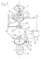
- an electric steering device of a truck in which the rotational movement of a designed as a steering wheel steering member 1 is transmitted via a steering shaft 2 to a steering signal generator 3.
- the mounted on a truck-mounted component 10 steering signal generator 3 is connected via a signal line 4 with an electrical control device 5, which controls a steering motor 6 via an electric steering motor 7.
- the steering motor 7 Via a steering gear 8, the steering motor 7 generates a steering movement of the steerable wheel 9.
- the actual steering position of the steerable wheel 9 is detected by means of a steering angle sensor 11 and also supplied via a signal line 11 to the control device.
- a braking device 13 is arranged on the steering shaft 2, which in this embodiment has a single, controllable by the control device 5 via a control line 14 brake element.
- the brake element comprises a non-rotatably attached to the truck component 10 fixed brake housing 15 and a brake body 16.
- the brake body 16 can be freely rotated relative to the brake housing 15, when the brake element is actuated, the brake body 16 is fixed in the brake housing 15 virtually torsionally rigid ,
- the brake body 16 is connected to the steering shaft 2 via a shaft connection with play.
- the shaft connection comprises a pin 17 which is arranged on the steering shaft 2 and which engages in a recess 18 on the brake body 16. Since the recess 18 is larger in the circumferential direction than the diameter of the pin 17, the shaft connection has play.
- the operation is as follows: When the steering member 1 is rotated starting from the position shown to the left (counterclockwise), the brake body 16 rotates, since the pin 17 abuts against the corresponding side of the recess 18. Now, if the steerable wheel 9 reaches its left stop, not shown, recognizes the control device 5 based on the corresponding output signal of the steering sensor 11 and causes an actuation of the brake element, so that the brake body 16 is fixed and thereby further rotation of the steering member 1 is prevented to the left , A turning back of the steering member 1 and the steering shaft 2 to the right, however, initially unhindered possible because this movement is not initially transmitted to the brake body 16 due to the game in the shaft connection.
- Figure 2 shows an identical with respect to the operation of the steering function arrangement.
- the brake device 13 arranged on the continuous steering shaft 2 has two brake elements each with a brake housing 15a, 15b and in each case a brake body 16a, 16b.
- the brake bodies 16a, 16b are connected by means of a respective freewheel 19a, 19b with the steering shaft 2, the freewheel 19a at any time a rotational movement of the steering shaft 2 and thus the steering member 1 to the right (clockwise) and the freewheel 19b at any time a rotational movement of the steering shaft. 2 to the left (counterclockwise).
- both brake elements are released as long as the steerable wheel 9 does not reach one of its stops.
- Both brake bodies 16a, 16b are freely rotatable in their brake housings 15a, 15b.
- the control device 5 actuates the first brake element, so that the brake body 16a is fixed in the brake housing 15a. Further rotation of the steering member 1 to the left is prevented.
- a turning of the steering member 1 to the right, so a return in the opposite direction, however, is possible by means of the freewheel 19a without noticeable resistance.
- the operation is analog, in which case the second brake body 16b is blocked and the freewheel 19b then allows only a rotation of the steering member 1 to the left.
Description
Die Erfindung betrifft eine Lenkvorrichtung für ein Flurförderzeug nach den Oberbegriffen der Ansprüche 1, 4 und 7.The invention relates to a steering device for a truck according to the preambles of
Bei derart ausgeführte Lenkvorrichtungen besteht zwischen dem meist als Lenkrad ausgeführten Lenkorgan und dem auf der Fahrbahn aufstehenden lenkbaren Rad keine mechanische Verbindung. Stattdessen wird mit dem beispielsweise als Winkelsensor ausgeführten Lenksignalgeber die Drehstellung des Lenkorgans erfasst und ein davon abhängiges elektrisches Signal erzeugt, das dann der elektrischen Steuervorrichtung zugeführt wird. Diese Steuervorrichtung wertet das elektrische Signal aus und steuert daraufhin den elektrischen Lenkmotor an, der eine Lenkbewegung des lenkbaren Rads bewirkt. Der tatsächlich Lenkwinkel des lenkbaren Rads wird von dem Lenkwinkelsensor erfasst und ebenfalls der Steuervorrichtung zugeführt. Derartige Lenkvorrichtungen werden üblicherweise als elektrische Lenkvorrichtungen oder "steer-by-wire" Lenkvorrichtungen bezeichnet.In such executed steering devices there is no mechanical connection between the usually executed as a steering wheel steering member and the upstanding on the roadway steerable wheel. Instead, the rotational position of the steering element is detected with the steering sensor, which is designed, for example, as an angle sensor, and generates a dependent electrical signal, which is then supplied to the electrical control device. This control device evaluates the electrical signal and then controls the electric steering motor, which causes a steering movement of the steerable wheel. The actual steering angle of the steerable wheel is detected by the steering angle sensor and also supplied to the control device. Such steering devices are commonly referred to as electric steering devices or "steer-by-wire" steering devices.
Die auf das lenkbare Rad wirkenden Lenkkräfte werden bei gattungsgemäßen Lenkvorrichtungen auf Grund der nicht vorhanden mechanischen Verbindung nicht auf das Lenkorgan übertragen. Um die Bedieneigenschaften einer mechanischen Lenkung nachzuempfinden und der Bedienperson ein Gefühl für die am lenkbaren Rad tatsächlich vorhandenen Lenkkräfte zu vermitteln, ist es beispielsweise aus der
Ein weiteres zweckmäßiges Merkmal von mechanischen Lenkungen besteht darin, dass ein Weiterdrehen des Lenkorgans nicht mehr möglich ist, wenn die gelenkten Räder ihren maximalen Lenkwinkel erreicht haben. Um diese Eigenschaft bei einer vollelektrischen Lenkung nachzubilden, schlägt die gattungsbildende Druckschrift
Der Erfindung liegt daher die Aufgabe zugrunde, eine Lenkvorrichtung der eingangs genannten Art zur Verfügung zu stellen, die einfach aufgebaut ist und bei der ein Erreichen des maximalen Lenkwinkels in vergleichbarer Weise am Lenkorgan spürbar ist, wie bei einer mechanischen Lenkung.The invention is therefore an object of the invention to provide a steering device of the type mentioned above, which is simple and in which a reaching the maximum steering angle in a comparable manner on the steering member is noticeable, as in a mechanical steering.
Diese Aufgabe wird erfindungsgemäß durch die kennzeichnenden Merkmale des Anspruchs 1 gelöst. Die Steuervorrichtung erkennt durch ein entsprechendes Signal des Lenkwinkelsensors, dass das lenkbare Rad seinen maximalen Lenkwinkel erreicht hat. Daraufhin wird die Bremsvorrichtung durch die Steuervorrichtung derart aktiviert, dass einem Weiterdrehen des Lenkorgans in Richtung einer weiteren Vergrößerung des Lenkwinkels ein Bremsmoment entgegenwirkt. Ein Zurückdrehen des Lenkorgans in die entgegengesetzte Richtung ist jedoch ungehindert möglich. Die Bedienperson erhält dadurch den Eindruck, als hätte das Lenkorgan einen Anschlag erreicht, der ein Weiterdrehen des Lenkorgans in eine erste Richtung verhindert, ein Zurückdrehen des Lenkorgans jedoch widerstandsfrei ermöglicht. Hierfür ist die Steuervorrichtung derart ausgeführt, dass die Bremsvorrichtung aktiviert wird, wenn der Lenkwinkelsensor erfasst, dass der Lenkwinkel des lenkbaren Rads dem maximalen Lenkwinkel entspricht, wobei die Bremsvorrichtung für die Drehrichtung des Lenkorgans, die einer Vergrößerung des Lenkwinkels entspricht, wirksam ist, und für die andere Drehrichtung des Lenkorgans, die einer Verringerung des Lenkwinkels entspricht, nicht wirksam ist. Die Bremsvorrichtung umfasst mindestens ein Bremselement, das ein nicht drehbares Bremsengehäuse und einen relativ zu dem Bremsengehäuse drehbar gelagerten Bremskörper aufweist, wobei durch Betätigen des Bremselements eine Rotationsbewegung des Bremskörpers abbremsbar ist. Das Bremsengehäuse ist beispielsweise starr an einem Rahmen des Flurförderzeugs befestigt. Der Bremskörper hingegen ist direkt oder indirekt mit dem Lenkorgan oder mit einer zum Lenkorgan gehörenden Lenkwelle verbunden, so dass eine Drehbewegung des Lenkorgans auf den Bremskörper übertragen werden kann. Eine Drehbewegung des Lenkorgans ist mittels einer Wellenverbindung auf den Bremskörper übertragbar, wobei die Wellenverbindung ein definiertes Spiel aufweist. Die genannte Wellenverbindung stellt also keine starre Drehverbindung zwischen Lenkorgan und Bremskörper dar, sondern weist in Rotationsrichtung ein Spiel auf, innerhalb dessen das Lenkorgan unabhängig von dem Bremskörper gedreht werden kann.This object is achieved by the characterizing features of
Hierbei ist die Wellenverbindung derart ausgeführt, dass nach einem Wechsel der Drehrichtung des Lenkorgans die Drehbewegung des Lenkorgans zunächst nicht auf den Bremskörper übertragen wird. Für den vorliegenden Betrachtungsfall am Endanschlag des lenkbaren Rads ergibt sich dabei folgende Wirkungsweise: Das Lenkorgan wird gemeinsam mit dem Bremskörper in die erste Richtung gedreht, bis das lenkbare Rad seinen mechanischen Lenkanschlag erreicht hat. Dies wird der Steuervorrichtung signalisiert, die daraufhin das Bremselement betätigt. Ein Weiterdrehen des Lenkorgans in die erste Richtung ist wegen des betätigten Bremselements praktisch nicht möglich. Ein Zurückdrehen des Lenkorgans in die entgegengesetzte zweite Richtung ist auf Grund des Spiels in der Wellenverbindung zunächst auch bei betätigtem Bremselement ungehindert möglich. Dieses Zurückdrehen wird von dem Lenksignalgeber erfasst und über die Steuervorrichtung in eine Lenkbewegung des lenkbaren Rads umgesetzt. Dieses befindet sich damit nicht mehr am Lenkanschlag, so dass die Steuervorrichtung das Bremselement löst, bevor das Ende des Spiels in der Wellenverbindung erreicht ist und die Drehbewegung des Lenkorgans auch in der zweiten Richtung auf den Bremskörper übertragen wird.Here, the shaft connection is designed such that after a change in the direction of rotation of the steering member, the rotational movement of the steering member is initially not transmitted to the brake body. For the present case of consideration at the end stop of the steerable wheel results in the following mode of action: The steering member is rotated together with the brake body in the first direction until the steerable wheel has reached its mechanical steering stop. This is signaled to the control device, which then actuates the brake element. Further rotation of the steering member in the first direction is practically impossible because of the actuated braking element. A turning back of the steering member in the opposite second direction is due to the game in the shaft connection initially possible unhindered even when the brake element is actuated. This turning back is detected by the steering signal generator and converted via the control device into a steering movement of the steerable wheel. This is thus no longer on the steering stop, so that the control device releases the brake element before the end of the game is achieved in the shaft connection and the rotational movement of the steering member is transmitted to the brake body in the second direction.
In einer möglichen Ausführungsform weist das Lenkorgan einen Mitnehmer auf, der in eine Aussparung am Bremskörper eingreift, wobei die Aussparung in Umfangsrichtung größer ist als der Mitnehmer. Der Mitnehmer kann beispielsweise von einem zylinderförmigen Zapfen gebildet sein, während die Aussparung als ein sich in Umfangsrichtung erstreckendes Langloch ausgeführt ist.In one possible embodiment, the steering member has a driver, which engages in a recess on the brake body, wherein the recess is larger in the circumferential direction than the driver. The driver may for example be formed by a cylindrical pin, while the recess is designed as a circumferentially extending slot.
Ebenso wird die gestellte Aufgabe durch die kennzeichnenden Merkmale des Anspruchs 4 gelöst. Diese Lösung sieht vor, dass das Lenkorgan mittels mindestens eines Freilaufs mit dem mindestens einen Bremskörper verbunden ist, wobei der Freilauf eine Bewegung des Lenkorgans in einer ersten Drehrichtung auf den Bremskörper überträgt und der Freilauf eine Bewegung des Lenkorgans in einer zweiten, zur ersten Drehrichtung entgegengesetzten Drehrichtung nicht auf den Bremskörper überträgt. An Stelle des Spiels in der Wellenverbindung ist hier ein Freilauf vorgesehen, der eine Drehbewegung des Lenkorgans in einer ersten Richtung jederzeit auf den Bremskörper überträgt, eine Drehbewegung des Lenkorgans in der entgegengerichteten zweiten Richtung jedoch unabhängig von dem Bremskörper, also auch bei stillstehendem Bremskörper ermöglicht.Likewise, the object is achieved by the characterizing features of
Hierbei umfasst die Bremsvorrichtung ein weiteres Bremselement, dessen Bremskörper ebenfalls mittels eines weiteren Freilaufs mit dem Lenkorgan verbunden ist, wobei der weitere Freilauf eine Bewegung des Lenkorgans in der zweiten Drehrichtung auf den Bremskörper überträgt und der weitere Freilauf eine Bewegung des Lenkorgans in der ersten Drehrichtung nicht auf den Bremskörper überträgt. Für den linksseitigen und den rechtsseitigen Endanschlag der gelenkten Räder ist damit jeweils ein Bremselement mit jeweils einem Freilauf vorgesehen.Here, the brake device comprises a further brake element, the brake body is also connected by means of another freewheel with the steering member, wherein the further freewheel transmits movement of the steering member in the second direction of rotation on the brake body and the further freewheel movement of the steering member in the first rotational direction not transfers to the brake body. For the left-side and the right-side end stop of the steered wheels thus a respective braking element is provided, each with a freewheel.
Die Steuervorrichtung ist derart ausgeführt, dass das erste Bremselement der Bremsvorrichtung aktiviert wird, wenn der Lenkwinkelsensor erfasst, dass der Lenkwinkel des lenkbaren Rads dem maximalen Lenkwinkel nach links entspricht, und das zweite Bremselement der Bremsvorrichtung aktiviert wird, wenn der Lenkwinkelsensor erfasst, dass der Lenkwinkel des lenkbaren Rads dem maximalen Lenkwinkel nach rechts entspricht.The control device is configured such that the first brake element of the brake device is activated when the steering angle sensor detects that the steering angle of the steerable wheel corresponds to the maximum steering angle to the left, and the second brake element of the braking device is activated when the steering angle sensor detects that the steering angle of the steerable wheel corresponds to the maximum steering angle to the right.
Eine weitere Lösung der gestellten Aufgabe ist durch die kennzeichnenden Merkmale des Anspruchs 7 gegeben. Diese Lösung sieht vor, dass die Bremsvorrichtung mindestens einen schaltbaren Freilauf umfasst, der ein nicht drehbares Freilaufgehäuse und einen relativ zu dem Freilaufgehäuse drehbar gelagerten Freilaufkörper aufweist, wobei in einer ersten Schaltstellung des Freilaufs der Freilaufkörper in beide Drehrichtungen drehbar ist und in einer zweiten Schaltstellung des Freilaufs der Freilaufkörper in einer ersten Drehrichtung drehbar ist und in einer zweiten Drehrichtung nicht drehbar ist. Ein schaltbarer Freilauf weist zwei Schaltstellungen auf, zwischen denen mittels elektrischer Signale umgeschaltet werden kann. Während des normalen Betriebs der Lenkvorrichtung ist der Freilaufkörper und damit das Lenkorgan in beide Drehrichtungen frei drehbar. Wenn das lenkbare Rad seine Endstellung erreicht, wird der Freilauf so geschaltet, dass ein Weiterdrehen des Lenkorgans in Richtung einer weiteren Vergrößerung des Lenkwinkels gesperrt ist, ein Zurückdrehen des Lenkorgans jedoch ungehindert möglich ist.Another solution of the problem is given by the characterizing features of
Um einen linken und einen rechten Lenkradanschlag darstellen zu können, umfasst die Bremsvorrichtung einen weiteren schaltbaren Freilauf, wobei in einer ersten Schaltstellung des weiteren Freilaufs der Freilaufkörper in beide Drehrichtungen drehbar ist und in einer zweiten Schaltstellung des weiteren Freilaufs der Freilaufkörper in der zweiten Drehrichtung drehbar ist und in der ersten Drehrichtung nicht drehbar ist.In order to represent a left and a right steering wheel stop, the brake device comprises a further switchable freewheel, wherein in a first switching position of the further freewheel the freewheel body is rotatable in both directions and in a second switching position of the further freewheel of the freewheel body in the second rotational direction is rotatable and is not rotatable in the first direction of rotation.
Zweckmäßigerweise ist das mindestens eine Bremselement von einer Magnetbremse gebildet. Die für die Bremsbetätigung erforderliche Kraft wird dabei elektrisch mittels eines Elektromagnets erzeugt. Die elektrische Ansteuerung durch die Steuervorrichtung gestaltet sich hierdurch besonders einfach.Conveniently, the at least one brake element is formed by a magnetic brake. The force required for the brake operation is generated electrically by means of an electromagnet. The electrical control by the control device designed by this particularly simple.
Wenn das mindestens eine Bremselement von einer Federspeicherbremse gebildet ist, ergibt sich der zusätzliche Vorteil, dass das Lenkrad bei außer Betrieb befindlichem Flurförderzeug blockiert ist. Die Lenkfunktion wird dann bei Inbetriebnahme des Flurförderzeugs frei gegeben, indem die Federspeicherbremsen gelöst werden.If the at least one brake element is formed by a spring-loaded brake, there is the additional advantage that the steering wheel is blocked when the truck is out of operation. The steering function is then released when the truck is started by releasing the spring-loaded brakes.
Weitere Vorteile und Einzelheiten der Erfindung werden anhand der in den schematischen Figuren dargestellten Ausführungsbeispiele näher erläutert. Dabei zeigt
Figur 1- eine elektrische Lenkvorrichtung mit einem Bremselement und einer spielbehafteten Wellenverbindung,
Figur 2- eine elektrische Lenkvorrichtung mit zwei Bremselementen und zwei Freiläufen.
- FIG. 1
- an electric steering device with a brake element and a shaft connection with play,
- FIG. 2
- an electric steering device with two brake elements and two freewheels.
In Figur 1 ist eine elektrische Lenkvorrichtung eines Flurförderzeugs dargestellt, bei der die Drehbewegung eines als Lenkrad ausgeführten Lenkorgans 1 über eine Lenkwelle 2 auf einen Lenksignalgeber 3 übertragen wird. Der an einem flurförderzeugfesten Bauteil 10 befestigte Lenksignalgeber 3 ist über eine Signalleitung 4 mit einer elektrischen Steuervorrichtung 5 verbunden, die über eine Steuerleitung 6 einen elektrischen Lenkmotor 7 ansteuert. Über ein Lenkgetriebe 8 erzeugt der Lenkmotor 7 eine Lenkbewegung des lenkbaren Rads 9. Die tatsächliche Lenkposition des lenkbaren Rads 9 wird mittels eines Lenkwinkelsensors 11 erfasst und über eine Signalleitung 11 ebenfalls der Steuervorrichtung zugeführt.In Figure 1, an electric steering device of a truck is shown, in which the rotational movement of a designed as a steering
Erfindungsgemäß ist auf der Lenkwelle 2 eine Bremsvorrichtung 13 angeordnet, die in dieser Ausführungsform ein einziges, von der Steuervorrichtung 5 über eine Steuerleitung 14 ansteuerbares Bremselement aufweist. Das Bremselement umfasst einen nicht drehbar an dem flurförderzeugfesten Bauteil 10 befestigtes Bremsengehäuse 15 und einen Bremskörper 16. Bei nicht betätigtem Bremselement kann der Bremskörper 16 relativ zu dem Bremsengehäuse 15 frei gedreht werden, bei betätigtem Bremselement ist der Bremskörper 16 praktisch drehstarr in dem Bremsengehäuse 15 festgelegt.According to the invention, a
Der Bremskörper 16 ist über eine spielbehaftete Wellenverbindung mit der Lenkwelle 2 verbunden. Im vorliegenden Ausführungsbeispiel umfasst die Wellenverbindung einen an der Lenkwelle 2 angeordneten Zapfen 17, der in eine Aussparung 18 am Bremskörper 16 eingreift. Da die Aussparung 18 in Umfangsrichtung größer ist als der Durchmesser des Zapfens 17, weist die Wellenverbindung Spiel auf.The
Die Funktionsweise ist folgende: Wenn das Lenkorgan 1 ausgehend von der dargestellten Position nach links (im Gegenuhrzeigersinn) gedreht wird, dreht sich der Bremskörper 16 mit, da der Zapfen 17 an der entsprechenden Seite der Ausnehmung 18 anliegt. Wenn nun das lenkbare Rad 9 seinen nicht dargestellten linken Anschlag erreicht, erkennt die Steuervorrichtung 5 dies anhand des entsprechenden Ausgangssignals des Lenksensors 11 und veranlasst ein Betätigen des Bremselements, sodass der Bremskörper 16 festgelegt wird und dadurch auch ein Weiterdrehen des Lenkorgans 1 nach links verhindert wird. Ein Zurückdrehen des Lenkorgans 1 und der Lenkwelle 2 nach rechts ist jedoch zunächst ungehindert möglich, da diese Bewegung auf Grund des Spiels in der Wellenverbindung zunächst nicht auf den Bremskörper 16 übertragen wird. Sobald jedoch das Lenkorgan 1 nach rechts gedreht wird, führt dies auch zu einer Lenkbewegung des lenkbaren Rads 9 nach rechts, wobei dieses seine Endposition verlässt, woraufhin die Steuervorrichtung 5 die Bremsvorrichtung 13 löst. Die Funktionsweise bei Erreichen des rechten Anschlags des lenkbaren Rads 9 ist analog.The operation is as follows: When the steering
Figur 2 zeigt eine hinsichtlich der Betätigung der Lenkfunktion identische Anordnung. Im Gegensatz zu der Anordnung gemäß Fig. 1 weist die an der durchgehenden Lenkwelle 2 angeordnete Bremsvorrichtung 13 zwei Bremselemente mit jeweils einem Bremsengehäuse 15a, 15b und jeweils einem Bremskörper 16a, 16b auf. Die Bremskörper 16a, 16b sind mittels jeweils eines Freilaufs 19a, 19b mit der Lenkwelle 2 verbunden, wobei der Freilauf 19a jederzeit eine Drehbewegung der Lenkwelle 2 und damit des Lenkorgans 1 nach rechts (im Uhrzeigersinn) und der Freilauf 19b jederzeit eine Drehbewegung der Lenkwelle 2 nach links (im Gegenuhrzeigersinn) zulässt.Figure 2 shows an identical with respect to the operation of the steering function arrangement. In contrast to the arrangement according to FIG. 1, the
Die Funktionsweise ist folgende: Während eines normalen Lenkvorgangs sind beide Bremselemente gelöst, solange das lenkbare Rad 9 nicht einen seiner Anschläge erreicht. Beide Bremskörper 16a, 16b sind dabei in ihren Bremsengehäusen 15a, 15b frei drehbar. Wenn das Lenkorgan 1 nun nach links gedreht wird, bis das lenkbare Rad 9 seinen linken Endanschlag erreicht, betätigt die Steuervorrichtung 5 das erste Bremselement, so dass der Bremskörper 16a im Bremsengehäuse 15a festgelegt wird. Ein Weiterdrehen des Lenkorgans 1 nach links ist dadurch verhindert. Ein Drehen des Lenkorgans 1 nach rechts, also ein Zurücklenken in die entgegengesetzte Richtung, ist jedoch mittels des Freilaufs 19a ohne spürbaren Widerstand möglich. Bei Erreichen des rechten Endanschlags des lenkbaren Rads 9 ist die Funktionsweise analog, wobei in diesem Fall der zweite Bremskörper 16b blockiert wird und der Freilauf 19b dann ausschließlich eine Drehung des Lenkorgans 1 nach links zulässt.The operation is as follows: During a normal steering operation both brake elements are released as long as the
Claims (10)
- Steering device for an industrial truck, having a rotatably mounted steering element (1), a steering signal transmitter (3) for sensing the rotational position of the steering element (1) and a brake device (13) for generating a braking torque which acts on the steering element (1), as well as a steerable wheel (9), a steering motor (7) for generating a steering movement of the steerable wheel (9) and a steering angle sensor (11) for sensing the steering angle of the steerable wheel (9), wherein the steering signal transmitter (3), the steering angle sensor (11), the steering motor (7) and the brake device (13) are connected to an electric control device (5) which is embodied in such a way that the brake device (13) is activated when the steering angle sensor (11) senses that the steering angle of the steerable wheel (9) corresponds to a maximum steering angle, wherein the brake device (13) for the direction of rotation of the steering element (1) which corresponds to an increase in the steering angle is active, and is inactive for the other direction of rotation of the steering element (1) which corresponds to a reduction in the steering angle, and wherein the brake device (13) comprises at least one brake element which has a non-rotatable brake housing (15, 15a, 15b) and a brake body (16, 16a, 16b) which is mounted so as to be rotatable in relation to the brake housing (15, 15a, 15b), wherein a rotational movement of the brake body (16, 16a, 16b) can be braked by activating the brake element, characterized in that a rotational movement of the steering element (1) can be transmitted to the brake body (16) by means of a shaft connection, wherein the shaft connection has a defined degree of play.
- Steering device according to Claim 1, characterized in that the shaft connection is embodied in such a way that after the direction of rotation of the steering element (1) changes the rotational movement of the steering element (1) is at first not transmitted to the brake body (16).
- Steering device according to Claim 1 or 2, characterized in that the steering element (1) has a driver (17) which engages in a cut-out on the brake body (16), wherein the cut-out (18) is larger in the circumferential direction than the driver (17).
- Steering device for an industrial truck, having a rotatably mounted steering element (1), a steering signal transmitter (3) for sensing the rotational position of the steering element (1) and a brake device (13) for generating a braking torque which acts on the steering element (1), as well as a steerable wheel (9), a steering motor (7) for generating a steering movement of the steerable wheel (9) and a steering angle sensor (11) for sensing the steering angle of the steerable wheel (9), wherein the steering signal transmitter (3), the steering angle sensor (11), the steering motor (7) and the brake device (13) are connected to an electric control device (5) which is embodied in such a way that the brake device (13) is activated when the steering angle sensor (11) senses that the steering angle of the steerable wheel (9) corresponds to a maximum steering angle, wherein the brake device (13) for the direction of rotation of the steering element (1) which corresponds to an increase in the steering angle is active, and is inactive for the other direction of rotation of the steering element (1) which corresponds to a reduction in the steering angle, and wherein the brake device (13) comprises at least one brake element which has a non-rotatable brake housing (15, 15a, 15b) and a brake body (16, 16a, 16b) which is mounted so as to be rotatable in relation to the brake housing (15, 15a, 15b), wherein a rotational movement of the brake body (16, 16a, 16b) can be braked by activating the brake element, characterized in that the steering element (1) is connected to the at least one brake body (16a) by means of at least one freewheel (19a), wherein the freewheel (19a) transmits a movement of the steering element (1) in a first direction of rotation to the brake body (16a), and the freewheel (19a) does not transmit a movement of the steering element (1) to the brake body (16a) in a second direction of rotation which is opposed to the first direction of rotation.
- Steering device according to Claim 4, characterized in that the brake device (13) comprises a further brake element whose brake body (16b) is also connected to the steering element (1) by means of a further freewheel (19b), wherein the further freewheel (19b) transmits a movement of the steering element (1) to the brake body (16b) in the second direction of rotation, and the further freewheel (19b) does not transmit a movement of the steering element (1) to the brake body (16b) in the first direction of rotation.
- Steering device according to Claim 5, characterized in that the control device (5) is embodied in such a way that the first brake element of the brake device (13) is activated if the steering angle sensor (11) senses that the steering angle of the steerable wheel (9) corresponds to the maximum steering angle to the left, and the second brake element of the brake device (13) is activated if the steering angle sensor (11) senses that the steering angle of the steerable wheel (9) corresponds to the maximum steering angle to the right.
- Steering device for an industrial truck, having a rotatably mounted steering element (1), a steering signal transmitter (3) for sensing the rotational position of the steering element (1) and a brake device (13) for generating a braking torque which acts on the steering element (1), as well as a steerable wheel (9), a steering motor (7) for generating a steering movement of the steerable wheel (9) and a steering angle sensor (11) for sensing the steering angle of the steerable wheel (9), wherein the steering signal transmitter (3), the steering angle sensor (11), the steering motor (7) and the brake device (13) are connected to an electric control device (5) which is embodied in such a way that the brake device (13) is activated when the steering angle sensor (11) senses that the steering angle of the steerable wheel (9) corresponds to a maximum steering angle, wherein the brake device (13) for the direction of rotation of the steering element (1) which corresponds to an increase in the steering angle is active, and is inactive for the other direction of rotation of the steering element (1) which corresponds to a reduction in the steering angle, characterized in that the brake device (13) comprises at least one switchable freewheel which has a non-rotatable freewheel housing and a free-wheel body which is mounted so as to be rotatable in relation to the freewheel housing, wherein in a first switched position of the freewheel the freewheel body can be rotated in both directions of rotation, and in a second switched position of the freewheel the freewheel body can be rotated in a first direction of rotation and cannot be rotated in a second direction of rotation.
- Steering device according to Claim 7, characterized in that the brake device (13) comprises a further switchable freewheel, wherein in a first switched position of the further freewheel the freewheel body can be rotated in both directions of rotation, and in a second switched position of the further freewheel the freewheel body can be rotated in the second direction of rotation and cannot be rotated in the first direction of rotation.
- Steering device according to one of Claims 1 to 6, characterized in that the at least one brake element is formed by an electromagnetic brake.
- Steering device according to one of Claims 1 to 6, characterized in that the at least one brake element is formed by a spring-loaded brake.
Applications Claiming Priority (2)
| Application Number | Priority Date | Filing Date | Title |
|---|---|---|---|
| DE2003154410 DE10354410A1 (en) | 2003-11-21 | 2003-11-21 | Steering device for a truck |
| DE10354410 | 2003-11-21 |
Publications (3)
| Publication Number | Publication Date |
|---|---|
| EP1533211A2 EP1533211A2 (en) | 2005-05-25 |
| EP1533211A3 EP1533211A3 (en) | 2005-08-17 |
| EP1533211B1 true EP1533211B1 (en) | 2007-10-17 |
Family
ID=34428839
Family Applications (1)
| Application Number | Title | Priority Date | Filing Date |
|---|---|---|---|
| EP04025710A Active EP1533211B1 (en) | 2003-11-21 | 2004-10-29 | Steering device for an industrial truck |
Country Status (2)
| Country | Link |
|---|---|
| EP (1) | EP1533211B1 (en) |
| DE (2) | DE10354410A1 (en) |
Cited By (1)
| Publication number | Priority date | Publication date | Assignee | Title |
|---|---|---|---|---|
| US7849955B2 (en) | 2008-02-05 | 2010-12-14 | Crown Equipment Corporation | Materials handling vehicle having a steer system including a tactile feedback device |
Families Citing this family (4)
| Publication number | Priority date | Publication date | Assignee | Title |
|---|---|---|---|---|
| JP4725132B2 (en) * | 2005-03-01 | 2011-07-13 | 日産自動車株式会社 | Steering control device |
| DE102006039549A1 (en) * | 2006-08-23 | 2008-03-06 | Jungheinrich Aktiengesellschaft | Industrial truck with an electric steering device and method for controlling a truck with an electric steering device |
| DE102007013172A1 (en) | 2007-03-20 | 2008-09-25 | Gebrüder Frei GbmH & Co. KG | Steering drive system |
| JP5945783B2 (en) * | 2012-09-13 | 2016-07-05 | 日本発條株式会社 | Ship helm equipment |
Family Cites Families (5)
| Publication number | Priority date | Publication date | Assignee | Title |
|---|---|---|---|---|
| DE4122064A1 (en) * | 1990-07-03 | 1992-01-09 | Zahnradfabrik Friedrichshafen | Switching clutch for steering column of motor vehicle - exerts balanced axial forces on control sleeve for non-jamming operation |
| GB2378165B (en) | 1999-07-14 | 2003-05-07 | Lansing Linde Ltd | Steering device for a vehicle |
| US6761243B2 (en) * | 2001-12-31 | 2004-07-13 | Visteon Global Technologies, Inc. | Steering control with variable damper assistance and method implementing the same |
| DE10249120A1 (en) * | 2002-10-22 | 2004-05-06 | Zf Lenksysteme Gmbh | Rack and pinion power steering for vehicles |
| US6926112B2 (en) * | 2003-10-16 | 2005-08-09 | Visteon Global Technologies, Inc. | End of travel system and method for steer by wire systems |
-
2003
- 2003-11-21 DE DE2003154410 patent/DE10354410A1/en not_active Withdrawn
-
2004
- 2004-10-29 EP EP04025710A patent/EP1533211B1/en active Active
- 2004-10-29 DE DE200450005251 patent/DE502004005251D1/en active Active
Non-Patent Citations (1)
| Title |
|---|
| None * |
Cited By (6)
| Publication number | Priority date | Publication date | Assignee | Title |
|---|---|---|---|---|
| US7849955B2 (en) | 2008-02-05 | 2010-12-14 | Crown Equipment Corporation | Materials handling vehicle having a steer system including a tactile feedback device |
| US7980352B2 (en) | 2008-02-05 | 2011-07-19 | Crown Equipment Corporation | Materials handling vehicle having a steer system including a tactile feedback device |
| US8172033B2 (en) | 2008-02-05 | 2012-05-08 | Crown Equipment Corporation | Materials handling vehicle with a module capable of changing a steerable wheel to control handle position ratio |
| US8412431B2 (en) | 2008-02-05 | 2013-04-02 | Crown Equipment Corporation | Materials handling vehicle having a control apparatus for determining an acceleration value |
| US8718890B2 (en) | 2008-02-05 | 2014-05-06 | Crown Equipment Corporation | Materials handling vehicle having a control apparatus for determining an acceleration value |
| US9421963B2 (en) | 2008-02-05 | 2016-08-23 | Crown Equipment Corporation | Materials handling vehicle having a control apparatus for determining an acceleration value |
Also Published As
| Publication number | Publication date |
|---|---|
| DE502004005251D1 (en) | 2007-11-29 |
| EP1533211A2 (en) | 2005-05-25 |
| EP1533211A3 (en) | 2005-08-17 |
| DE10354410A1 (en) | 2005-06-23 |
Similar Documents
| Publication | Publication Date | Title |
|---|---|---|
| DE112019002990B4 (en) | Steer-by-wire steering device and vehicle | |
| EP1250251B1 (en) | Coupling for a steer-by-wire steering system | |
| DE60202074T2 (en) | STEERING UNIT FOR STEER-BY-WIRE STEERING | |
| EP3424797B1 (en) | Clutch for an automotive vehicle | |
| EP2417001B1 (en) | Steering wheel for a motor vehicle having superimposed steering | |
| DE102004027610A1 (en) | Pedal unit and pedal assembly for motor vehicle | |
| DE212004000037U1 (en) | Toy vehicle | |
| EP1583680A1 (en) | Steering column for a motor vehicle | |
| DE19902556B4 (en) | Steering gear with redundant drive | |
| DE4011947A1 (en) | VEHICLE STEERING SYSTEM | |
| DE102008023759A1 (en) | Steering device for a motor vehicle with a steering wheel, a steering shaft and a superposition gear | |
| DE102007012278A1 (en) | joystick | |
| DE102006045382A1 (en) | Steering system for motor vehicle, has driving authorization system that causes switching of locking device in release condition when driving authorization system detects unauthorized driver | |
| DE10126928A1 (en) | Stabilizer for vehicle has locking disk and casing fixed to second shaft | |
| EP1533211B1 (en) | Steering device for an industrial truck | |
| DE10344479A1 (en) | Electrically operated steering lock device | |
| DE102019202294A1 (en) | Steer limiting device, steer-by-wire system and vehicle | |
| DE102005049012B3 (en) | Drive wheel for wheel chair, has, full-floating axle operatively connected with wheel chair by locking device, where electromechanical hand brakes and locking device are actuated by common control pin | |
| DE60314927T2 (en) | Variable ratio device | |
| DE19911892A1 (en) | Device for steering a vehicle | |
| EP1121278B1 (en) | Control device that blocks ignition and steering in a motor vehicle | |
| DE3612619C2 (en) | ||
| DE3505325A1 (en) | DEVICE FOR FRICTION-FREE COUPLING, WHICH ALLOWS AN OPTIONAL DISCONNECTING OF AN OUTPUT SHAFT FROM A DRIVE SHAFT AND AT THE SAME TIME LEASES A BRAKING OF THE DISCONNECTED OUTPUT SHAFT, WITH THE FOLLOWING DEVICES WITH THE FOLLOWING DEVICES | |
| DE4340203C2 (en) | Electrically powered steering device | |
| DE19748326C1 (en) | Motor vehicle anti-theft protection device |
Legal Events
| Date | Code | Title | Description |
|---|---|---|---|
| PUAI | Public reference made under article 153(3) epc to a published international application that has entered the european phase |
Free format text: ORIGINAL CODE: 0009012 |
|
| AK | Designated contracting states |
Kind code of ref document: A2 Designated state(s): AT BE BG CH CY CZ DE DK EE ES FI FR GB GR HU IE IT LI LU MC NL PL PT RO SE SI SK TR |
|
| AX | Request for extension of the european patent |
Extension state: AL HR LT LV MK |
|
| PUAL | Search report despatched |
Free format text: ORIGINAL CODE: 0009013 |
|
| AK | Designated contracting states |
Kind code of ref document: A3 Designated state(s): AT BE BG CH CY CZ DE DK EE ES FI FR GB GR HU IE IT LI LU MC NL PL PT RO SE SI SK TR |
|
| AX | Request for extension of the european patent |
Extension state: AL HR LT LV MK |
|
| 17P | Request for examination filed |
Effective date: 20060124 |
|
| AKX | Designation fees paid |
Designated state(s): DE FR GB IT SE |
|
| 17Q | First examination report despatched |
Effective date: 20060407 |
|
| GRAP | Despatch of communication of intention to grant a patent |
Free format text: ORIGINAL CODE: EPIDOSNIGR1 |
|
| RIC1 | Information provided on ipc code assigned before grant |
Ipc: B62D 6/00 20060101AFI20070612BHEP |
|
| GRAS | Grant fee paid |
Free format text: ORIGINAL CODE: EPIDOSNIGR3 |
|
| GRAA | (expected) grant |
Free format text: ORIGINAL CODE: 0009210 |
|
| AK | Designated contracting states |
Kind code of ref document: B1 Designated state(s): DE FR GB IT SE |
|
| REG | Reference to a national code |
Ref country code: GB Ref legal event code: FG4D Free format text: NOT ENGLISH |
|
| REF | Corresponds to: |
Ref document number: 502004005251 Country of ref document: DE Date of ref document: 20071129 Kind code of ref document: P |
|
| REG | Reference to a national code |
Ref country code: SE Ref legal event code: TRGR |
|
| RAP2 | Party data changed (patent owner data changed or rights of a patent transferred) |
Owner name: STILL WAGNER GMBH |
|
| GBV | Gb: ep patent (uk) treated as always having been void in accordance with gb section 77(7)/1977 [no translation filed] | ||
| EN | Fr: translation not filed | ||
| PLBE | No opposition filed within time limit |
Free format text: ORIGINAL CODE: 0009261 |
|
| STAA | Information on the status of an ep patent application or granted ep patent |
Free format text: STATUS: NO OPPOSITION FILED WITHIN TIME LIMIT |
|
| 26N | No opposition filed |
Effective date: 20080718 |
|
| PG25 | Lapsed in a contracting state [announced via postgrant information from national office to epo] |
Ref country code: FR Free format text: LAPSE BECAUSE OF FAILURE TO SUBMIT A TRANSLATION OF THE DESCRIPTION OR TO PAY THE FEE WITHIN THE PRESCRIBED TIME-LIMIT Effective date: 20080801 |
|
| PG25 | Lapsed in a contracting state [announced via postgrant information from national office to epo] |
Ref country code: GB Free format text: LAPSE BECAUSE OF FAILURE TO SUBMIT A TRANSLATION OF THE DESCRIPTION OR TO PAY THE FEE WITHIN THE PRESCRIBED TIME-LIMIT Effective date: 20071017 |
|
| PG25 | Lapsed in a contracting state [announced via postgrant information from national office to epo] |
Ref country code: FR Free format text: LAPSE BECAUSE OF FAILURE TO SUBMIT A TRANSLATION OF THE DESCRIPTION OR TO PAY THE FEE WITHIN THE PRESCRIBED TIME-LIMIT Effective date: 20071031 |
|
| PGFP | Annual fee paid to national office [announced via postgrant information from national office to epo] |
Ref country code: IT Payment date: 20081025 Year of fee payment: 5 |
|
| PG25 | Lapsed in a contracting state [announced via postgrant information from national office to epo] |
Ref country code: IT Free format text: LAPSE BECAUSE OF NON-PAYMENT OF DUE FEES Effective date: 20091029 |
|
| REG | Reference to a national code |
Ref country code: DE Ref legal event code: R081 Ref document number: 502004005251 Country of ref document: DE Owner name: STILL GMBH, DE Free format text: FORMER OWNER: STILL WAGNER GMBH, 72766 REUTLINGEN, DE Effective date: 20110405 |
|
| REG | Reference to a national code |
Ref country code: DE Ref legal event code: R082 Ref document number: 502004005251 Country of ref document: DE Representative=s name: GEIRHOS & WALLER PATENT- UND RECHTSANWAELTE, DE |
|
| REG | Reference to a national code |
Ref country code: DE Ref legal event code: R082 Ref document number: 502004005251 Country of ref document: DE Representative=s name: PATENTSHIP PATENTANWALTSGESELLSCHAFT MBH, DE Effective date: 20111010 Ref country code: DE Ref legal event code: R081 Ref document number: 502004005251 Country of ref document: DE Owner name: STILL GMBH, DE Free format text: FORMER OWNER: KION WAREHOUSE SYSTEMS GMBH, 72766 REUTLINGEN, DE Effective date: 20111010 Ref country code: DE Ref legal event code: R082 Ref document number: 502004005251 Country of ref document: DE Representative=s name: GEIRHOS & WALLER PATENT- UND RECHTSANWAELTE, DE Effective date: 20111010 |
|
| REG | Reference to a national code |
Ref country code: DE Ref legal event code: R082 Ref document number: 502004005251 Country of ref document: DE Representative=s name: PATENTSHIP PATENTANWALTSGESELLSCHAFT MBH, DE |
|
| REG | Reference to a national code |
Ref country code: DE Ref legal event code: R082 Ref document number: 502004005251 Country of ref document: DE Representative=s name: PATENTSHIP PATENTANWALTSGESELLSCHAFT MBH, DE |
|
| PGFP | Annual fee paid to national office [announced via postgrant information from national office to epo] |
Ref country code: SE Payment date: 20221020 Year of fee payment: 19 Ref country code: DE Payment date: 20221020 Year of fee payment: 19 |