EP1531455A2 - Beamforming method for a transducer array - Google Patents
Beamforming method for a transducer array Download PDFInfo
- Publication number
- EP1531455A2 EP1531455A2 EP04025031A EP04025031A EP1531455A2 EP 1531455 A2 EP1531455 A2 EP 1531455A2 EP 04025031 A EP04025031 A EP 04025031A EP 04025031 A EP04025031 A EP 04025031A EP 1531455 A2 EP1531455 A2 EP 1531455A2
- Authority
- EP
- European Patent Office
- Prior art keywords
- delay times
- value
- corrected
- magnitude
- group signal
- Prior art date
- Legal status (The legal status is an assumption and is not a legal conclusion. Google has not performed a legal analysis and makes no representation as to the accuracy of the status listed.)
- Withdrawn
Links
Images

Classifications
-
- G—PHYSICS
- G01—MEASURING; TESTING
- G01S—RADIO DIRECTION-FINDING; RADIO NAVIGATION; DETERMINING DISTANCE OR VELOCITY BY USE OF RADIO WAVES; LOCATING OR PRESENCE-DETECTING BY USE OF THE REFLECTION OR RERADIATION OF RADIO WAVES; ANALOGOUS ARRANGEMENTS USING OTHER WAVES
- G01S3/00—Direction-finders for determining the direction from which infrasonic, sonic, ultrasonic, or electromagnetic waves, or particle emission, not having a directional significance, are being received
- G01S3/80—Direction-finders for determining the direction from which infrasonic, sonic, ultrasonic, or electromagnetic waves, or particle emission, not having a directional significance, are being received using ultrasonic, sonic or infrasonic waves
- G01S3/802—Systems for determining direction or deviation from predetermined direction
- G01S3/808—Systems for determining direction or deviation from predetermined direction using transducers spaced apart and measuring phase or time difference between signals therefrom, i.e. path-difference systems
- G01S3/8083—Systems for determining direction or deviation from predetermined direction using transducers spaced apart and measuring phase or time difference between signals therefrom, i.e. path-difference systems determining direction of source
-
- G—PHYSICS
- G10—MUSICAL INSTRUMENTS; ACOUSTICS
- G10K—SOUND-PRODUCING DEVICES; METHODS OR DEVICES FOR PROTECTING AGAINST, OR FOR DAMPING, NOISE OR OTHER ACOUSTIC WAVES IN GENERAL; ACOUSTICS NOT OTHERWISE PROVIDED FOR
- G10K11/00—Methods or devices for transmitting, conducting or directing sound in general; Methods or devices for protecting against, or for damping, noise or other acoustic waves in general
- G10K11/18—Methods or devices for transmitting, conducting or directing sound
- G10K11/26—Sound-focusing or directing, e.g. scanning
- G10K11/34—Sound-focusing or directing, e.g. scanning using electrical steering of transducer arrays, e.g. beam steering
- G10K11/341—Circuits therefor
- G10K11/346—Circuits therefor using phase variation
Definitions
- the invention relates to a method for forming a Group signal of a directional characteristic of a Converter arrangement in the preamble of claim 1 defined genus.
- the so-called beamforming, of nonlinear Antennas become the received signals for the purpose of their time - delayed as if the incident sound wave front the group of common operated electroacoustic transducer at their fictitious location on one to the main direction of the directional characteristic right-angled aligned line simultaneously.
- the fictional places are made by rectangular projection of the actual locations of the transducers on the said line receive.
- the size of the individual delay time for each transducer is expressed as a quotient of the length of the Projection beam, so the distance of the fictitious location of Transducer from the actual transducer location, and an assumed transducer location mean value of the speed of sound.
- the calculated time delays become common to all group signals stored for different directions of arrival the sound waves have been formed.
- Main direction of the directional characteristic the direction of incidence the sound waves received by the transducer assembly determined, and with side lobes or side lobes, by an amplitude graduation of the time-delayed samples, the so-called shading, e.g. by a Dolph-Chebyshev weighting, be reduced.
- the transducer through which the transducers cover acoustically transparent envelope By changing the speed of sound in the field of application of Transducer arrangement, by exceeding installation tolerances the transducer through which the transducers cover acoustically transparent envelope, its thickness and material constant may have relatively large tolerances, the soft calculated and stored delay times more or less dependent on the correct delay times, so that the addition of the received signals is no longer accurate Conphas takes place. This reduces the maximum Receive level of the group signal, ie the output level of the Beamformer.
- the directional characteristic is not exact formed, and accordingly is the bearing of a sound source fraught with more or less big mistake.
- the invention is based on the object in a method of the type mentioned above for an exact Direction formation required, correct, individual Delay times for the received signals of the converter as well with changing boundary conditions, like variation of the Speed of sound or unrecognizable geometry errors in the transducer assembly to determine exactly.
- the inventive method has the advantage that the Beamforming, ie the formation of the group signal of Directional characteristic of the transducer arrangement, with correct Delay times is carried out by the individual Case of application are adapted, so that the output signal of Beamformers is always maximum.
- the inventive method takes advantage of the fact that the output level or the output power or another characteristic quantity the output signal of the beamformer, that is the group signal, is maximum only with correctly calculated delay times.
- the group signal is a first magnitude value, e.g. a first level value, with respect to the Initial delay times reduced delay times and a second size value, e.g. a second level value, with compared to the Clearverzögerungsterrorism enlarged Delay times determined.
- the two size values, e.g. Level value become the one with the Clearverzögerungs founded certain original size value, the Original size value, e.g. Source level value, in relation set.
- the latter can with two alternatives Procedures are carried out in the claims. 4 and 5 and 6 and 7 are given.
- Embodiment of a transducer assembly 10 the groups of jointly operated electroacoustic transducers 11 has, which are arranged on a curved support 12, a so-called cylinder base is used on its cylindrical surface For example, 21 transducers 11 equidistant in the circumferential direction are arranged on a circular line. How not next are shown are usually to achieve a vertical focusing of the transducer array, i. one smallest possible vertical opening angle of Cylinder base, several in the axial direction of the cylinder underlying transducers to a so-called. Stave summarized. Each of the twenty-one transducers 11 in FIG. 1 belongs to a Stave.
- a group of common operated converters 11 or staves includes in Embodiment of FIG. 1 eight transducers 11 and staves.
- the Group signal has the group of eight jointly operated electroacoustic transducer 11 or Staves a Directional characteristic whose main direction in Fig. 1 with I is marked.
- This directional characteristic of Transducer group also called group characteristic, becomes the horizontal scanning of the environment of the cylinder base pivoted electronically, adding by adding a Transducer 11 at one end of the transducer group and take away a transducer 11 at the other end of the transducer group the Main direction I of the directional characteristic horizontal can be rotated gradually 360 °.
- a sound wavefront emitted by a sound source passes over the individual transducers 11, and the jointly operated eight transducers 11 of the transducer group each provide at their output a corresponding electrical output signal, which is referred to below as a received signal.
- the received signals are time-delayed in a known manner and added to the group signal in a concave manner.
- the delay time t i for each of the received signals is calculated as a quotient of the distance a i and the speed of sound c.
- the distance a i for each transducer 11 of the eight jointly operated transducers 11 results from the projection of the actual location of the electroacoustic transducer 11 on the carrier 12 along the main direction I onto a straight line 13 which represents the locations of the first and last converter 11 of the group connects to each other.
- the distance a i is the length of the respective projection beam. This results in the delay time t 2 for the second transducer 11 in the group of eight transducers to a 2 / c, the delay time t 3 for the third transducer 11 in the transducer group to a 3 / c, etc., where for c a mean speed of sound Is accepted.
- This set of delay times t i in the following referred to as ⁇ 0 , is stored in a memory.
- an equal set of delay times are stored for all the pivoted main directions of the directional characteristic of the transducer groups formed on the cylinder base of eight transducers.
- the set of stored delay times ⁇ 0, however, may deviate more or less from the correct time delay times, for example by deviating the speed of sound in the field of use from the mean sound velocity underlying the calculation by non-compliance with installation tolerances of the converters within the cylinder base , by influences of the enveloping body which covers the transducer arrangement etc.
- the group signal with the correct delay times now becomes a size of the group signal formed with the stored set of calculated delay times ⁇ 0 , eg the magnitude, the power or the level of the group signal, selected as the evaluation variable for the group signal and the stored delay times ⁇ 0 as long as reduced and increased until the considered size of the group signal reaches a maximum value.
- the maximum of the size considered is an indication that now the correct delay times have been set, which give the correct, the directional characteristic of the transducer assembly-determining group signal.
- Size of the group signal is the level P of the Group signal selected.
- the reduction or enlargement of the first delay times is performed with an average sound velocity c increased or decreased by a constant increment .DELTA.c.
- the level values P -1 and P +1 are determined in the same way as the original level value P 0 by delaying and adding the received signals of the transducers 11 by the reduced delay times.
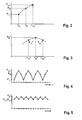
- FIG. 2 shows the two level values P -1 and P +1 determined with reduced delay times ⁇ -1 and increased delay times ⁇ +1 together with the original level value P 0 , which was determined using the stored first delay times ⁇ 0 .
- the first and second level value P -1 and P +1 are now set with respect to the origin level value P 0, here compared to the level value P 0 with respect to their size. If the first or second level value is smaller and the second or first level value is greater than the original level value P 0 , ie the level value P 0 is not greater than both level values P -1 and P +1 , then this is an indication that the original level value P 0 is not maximal. This is the case with the level values shown in FIG.
- the stored first deceleration values ⁇ 0 are then changed, for example by changing the value of the average sound velocity, whereby the individual delay times t 2 to t 7 in the set ⁇ 0 of the stored delay times are changed accordingly.
- the received signals are time-delayed and in turn added and the corrected original level value P * 0 of the group signal thus obtained is formed.
- the method steps described above namely determination of a new first and second level value P * -1 and P * +1 , are repeated by adding the received signals, which have been delayed with reduced or increased delay times compared to the corrected first delay times ⁇ * 0 .
- the corrected original level P * 0 and the two new level values P * -1 and P * +1 are again compared with each other. If it is found in this comparison that the corrected original level value P * 0 is greater than the two new level values P * -1 and P * +1 , this is an indication that the corrected original level value P * 0 is now maximal.
- the stored delay times ⁇ 0 are corrected again. This is repeated until the conditions according to FIG. 3 have occurred, that is to say the last corrected corrected original level value P * 0 is greater than the two new level values P * -1 and P * calculated with the reduced and enlarged corrected delay times ⁇ * 0 . +1 .
- the correction of the first delay times ⁇ 0 occurs at longer delay times when the second level value P +1 is greater than the original level value P 0 , and at smaller delay times when the second level value P +1 is smaller than the original level value P 0 .
- the first and second level values P -1 and P +1 calculated in relation to the initial level value P 0 calculated with the stored first delay times ⁇ 0 are not compared by magnitude comparison of the level values, but by means of a frequency analysis.
- the level values P -1 , P 0 and P +1 shown in FIG. 2 are sampled backwards and forwards several times in the mentioned sequences and the sequence of the sampled values, as shown in FIG. 4, is subjected to a frequency analysis.
- the spectral frequency determined by the frequency analysis is compared with the sampling frequency. If the spectral frequency is less than twice the sampling frequency, this is an indication that the original level value P 0 is not a maximum.
- the set of stored first delay times ⁇ 0 is again changed, and the received signals delayed by the corrected first delay times ⁇ 0 of the converters are added to the corrected group signal and the level P * 0 of the corrected group signal is determined.
- the received signals with delay times which are once reduced compared to the corrected first delay times and once enlarged, delayed and added to group signals and from the new level values P * -1 and P * +1 determined, as eg Fig. 3 are shown.
- These level values are sampled again in the same way, and the sequence of samples, as shown for example in FIG. 5, is subjected to a frequency analysis. If the spectral frequency determined with the frequency analysis is equal to twice the sampling frequency, as assumed in the example of FIGS. 4 and 5, then the changed original level value P * 0 represents a maximum.
- the optimal direction of the correction of the first delay times ⁇ 0 ie to know whether the first delay times ⁇ 0 must be shifted to larger or smaller delay times to the maximum of the level value of the group signal to reach.
- the phase of the Fourier signal obtained from a complex Fourier transformation of the sequence of samples is determined. If the phase is positive, the first delay times ⁇ 0 are increased, if it is negative, the first delay times are reduced. This is also applied in the same way to the respective corrected first delay times ⁇ * 0 , specifically until the spectral frequency is equal to twice the sampling frequency, the last modified original level value P * 0 being maximum.
- converter arrangements which are non-linear, i. at Transducer assemblies in which the converter is not on a elongated, straight beam or a flat surface are arranged, and the at least partially converter or staves, which with respect to a Sound incidence direction axis or mirror symmetry are arranged.
- Such converters are the so-called cylinder bases, where the transducers are in staves about the circumference of a Cylinders are arranged distributed, or so-called.
- Conformal Arrays as they are preferably on underwater running bodies are arranged and at the bow or head one to the pre-alignment have symmetrical arrangement of the transducer.
Abstract
Description
Die Erfindung betrifft ein Verfahren zur Bildung eines
Gruppensignals einer Richtcharakteristik einer
Wandleranordnung der im Oberbegriff des Anspruchs 1
definierten Gattung.The invention relates to a method for forming a
Group signal of a directional characteristic of a
Converter arrangement in the preamble of
Bei der Bildung eines Gruppensignals einer Richtcharakteristik, dem sog. Beamforming, von nichtlinearen Antennen werden die Empfangssignale zum Zwecke ihrer konphasen Aufsummierung zeitlich so verzögert, als ob die einfallenden Schallwellenfront die Gruppe der gemeinsam betriebenen elektroakustischen Wandler an deren fiktiven Ort auf einer zur Hauptrichtung der Richtcharakteristik rechtwinklig ausgerichteten Linie gleichzeitig erreicht. Die fiktiven Orte werden durch rechtwinklige Projektion der tatsächlichen Orte der Wandler auf die genannte Linie erhalten. Die Größe der individuellen Verzögerungszeit für jeden Wandler wird als Quotient aus der Länge des Projektionsstrahls, also dem Abstand des fiktiven Orts des Wandlers vom tatsächlichen Wandlerort, und einem angenommenen mittleren Wert der Schallgeschwindigkeit bestimmt. Die berechneten Zeitverzögerungen werden für alle Gruppensignale abgespeichert, die für unterschiedliche Einfallsrichtungen der Schallwellen gebildet worden sind. When forming a group signal a Directional characteristic, the so-called beamforming, of nonlinear Antennas become the received signals for the purpose of their time - delayed as if the incident sound wave front the group of common operated electroacoustic transducer at their fictitious location on one to the main direction of the directional characteristic right-angled aligned line simultaneously. The fictional places are made by rectangular projection of the actual locations of the transducers on the said line receive. The size of the individual delay time for each transducer is expressed as a quotient of the length of the Projection beam, so the distance of the fictitious location of Transducer from the actual transducer location, and an assumed transducer location mean value of the speed of sound. The calculated time delays become common to all group signals stored for different directions of arrival the sound waves have been formed.
Bei einem bekannten Verfahren zur Richtungsbildung oder zum Beamforming (US 4 060 792) werden die Empfangssignale der elektroakustischen Wandler verstärkt, geklippt und mit einer Abtastfrequenz, die größer ist als das Zweifache der zugelassenen größten Signalfrequenz der Empfangssignale abgetastet. Die Abtastwerte oder Samples werden einem sog. Beamformer zugeführt, der zunächst die Abtastwerte um die zugehörigen, abgespeicherten Verzögerungszeiten verzögert und dann die zeitverzögerten Abtastwerte konphas addiert. Das Ergebnis des Beamforming ist die Richtcharakteristik der Wandleranordnung mit einer Hauptkeule, deren Achse, die sog. Hauptrichtung der Richtcharakteristik, die Einfallsrichtung der von der Wandleranordnung empfangenen Schallwellen bestimmt, und mit Nebenkeulen oder Nebenzipfeln, die durch eine Amplitudenstaffelung der zeitverzögerten Abtastwerte, das sog. Shading, z.B. durch eine Dolph-Tschebyschew-Wichtung, reduziert werden.In a known method for directional formation or Beamforming (US 4 060 792) are the received signals of electroacoustic transducer amplified, clipped and with a Sampling frequency that is greater than twice the permitted maximum signal frequency of the received signals sampled. The samples or samples are called a so-called. Beamformer first supplied the samples around the associated, stored delay times delayed and then the time-delayed samples are added in quadrature. The Result of the beamforming is the directivity of the Transducer assembly with a main lobe, whose axis, the so-called. Main direction of the directional characteristic, the direction of incidence the sound waves received by the transducer assembly determined, and with side lobes or side lobes, by an amplitude graduation of the time-delayed samples, the so-called shading, e.g. by a Dolph-Chebyshev weighting, be reduced.
Durch Änderung der Schallgeschwindigkeit im Einsatzgebiet der Wandleranordnung, durch Überschreitung von Einbautoleranzen der Wandler, durch den die Wandler abdeckenden akustisch transparenten Hüllkörper, dessen Dicke und Materialkonstante relativ große Toleranzen aufweisen können, weichen die berechneten und abgespeicherten Verzögerungszeiten mehr oder weniger stark von den korrekten Verzögerungszeiten ab, so dass die Addition der Empfangssignale nicht mehr exakt konphas erfolgt. Dadurch verkleinert sich der maximale Empfangspegel des Gruppensignals, also der Ausgangspegel des Beamformers. Die Richtcharakteristik ist nicht exakt gebildet, und entsprechend ist die Peilung einer Schallquelle mit mehr oder weniger großem Fehler behaftet. By changing the speed of sound in the field of application of Transducer arrangement, by exceeding installation tolerances the transducer through which the transducers cover acoustically transparent envelope, its thickness and material constant may have relatively large tolerances, the soft calculated and stored delay times more or less dependent on the correct delay times, so that the addition of the received signals is no longer accurate Conphas takes place. This reduces the maximum Receive level of the group signal, ie the output level of the Beamformer. The directional characteristic is not exact formed, and accordingly is the bearing of a sound source fraught with more or less big mistake.
Der Erfindung liegt die Aufgabe zugrunde, bei einem Verfahren der eingangs genannten Art die für eine exakte Richtungsbildung erforderlichen, korrekten, individuellen Verzögerungszeiten für die Empfangssignale der Wandler auch bei sich ändernden Randbedingungen, wie Variation der Schallgeschwindigkeit oder nicht erkennbare Geometriefehler in der Wandleranordnung, exakt zu bestimmen.The invention is based on the object in a method of the type mentioned above for an exact Direction formation required, correct, individual Delay times for the received signals of the converter as well with changing boundary conditions, like variation of the Speed of sound or unrecognizable geometry errors in the transducer assembly to determine exactly.
Die Aufgabe wird erfindungsgemäß durch die Merkmale im
Anspruch 1 gelöst.The object is achieved by the features in the
Das erfindungsgemäße Verfahren hat den Vorteil, dass das Beamforming, also die Bildung des Gruppensignals der Richtcharakteristik der Wandleranordnung, mit korrekten Verzögerungszeiten durchgeführt wird, die dem einzelnen Einsatzfall angepasst sind, so dass das Ausgangssignal des Beamformers stets maximal ist. Das erfindungsgemäße Verfahren macht sich die Tatsache zunutze, dass der Ausgangspegel oder die Ausgangsleistung oder eine andere charakteristische Größe des Ausgangssignals des Beamformers, also des Gruppensignals, nur bei korrekt berechneten Verzögerungszeiten maximal ist. Indem das Verfahren die berechneten und abgespeicherten Verzögerungszeiten solange variiert, bis ein eindeutiges Maximum des Ausgangspegels oder der Ausgangsleistung vorliegt, ist sichergestellte, dass die zuletzt eingestellten Verzögerungszeiten die für die konphase Addition der Empfangssignale korrekten Verzögerungszeiten sind, die Richtungsbildung also mit größtmöglicher Genauigkeit vorgenommen worden ist.The inventive method has the advantage that the Beamforming, ie the formation of the group signal of Directional characteristic of the transducer arrangement, with correct Delay times is carried out by the individual Case of application are adapted, so that the output signal of Beamformers is always maximum. The inventive method takes advantage of the fact that the output level or the output power or another characteristic quantity the output signal of the beamformer, that is the group signal, is maximum only with correctly calculated delay times. By the method the calculated and stored Delay times as long as varied until a clear Maximum of output level or output power is present, is ensured that the last set Delay times for the consequent addition of the Receive signals are correct delay times, the Direction formation with the greatest possible accuracy has been made.
Zweckmäßige Ausführungsformen des erfindungsgemäßen Verfahren mit vorteilhaften Weiterbildungen und Ausgestaltungen der Erfindung ergeben sich aus den weiteren Ansprüchen. Expedient embodiments of the method according to the invention with advantageous developments and refinements of Invention will become apparent from the other claims.
Gemäß einer bevorzugten Ausführungsform der Erfindung wird die Berechnung der Verzögerungszeiten für die Empfangssignale aus der Geometrie der Wandleranordnung unter Berücksichtung einer mittleren Schallgeschwindigkeit abgeleitet und für die Berechnung der vergrößerten bzw. verkleinerten Verzögerungszeiten ein konstantes Inkrement der Schallgeschwindigkeit vorgegeben, um das die mittlere Schallgeschwindigkeit verkleinert bzw. vergrößert wird.According to a preferred embodiment of the invention the calculation of the delay times for the received signals from the geometry of the transducer assembly under consideration derived a mean speed of sound and for the Calculation of the enlarged or reduced Delay times a constant increment of Sound velocity given to the middle Speed of sound is reduced or increased.
Gemäß einer vorteilhaften Ausführungsform der Erfindung wird zur Bestimmung des Maximum des Größenwerts, z.B. des Pegelwerts, des Gruppensignals ein erster Größenwert, z.B. ein erster Pegelwert, mit gegenüber den Erstverzögerungszeiten verkleinerten Verzögerungszeiten und ein zweiter Größenwert, z.B. ein zweiter Pegelwert, mit gegenüber den Erstverzögerungszeiten vergrößerten Verzögerungszeiten bestimmt. Die beiden Größenwerte, z.B. Pegelwert, werden zu dem mit den Erstverzögerungszeiten bestimmten ursprünglichen Größenwert, dem Ursprungsgrößenwert, z.B. Ursprungspegelwert, in Bezug gesetzt. Letzteres kann mit zwei alternativen Verfahrensweisen vorgenommen werden, die in den Ansprüchen 4 und 5 sowie 6 und 7 angegebenen sind.According to an advantageous embodiment of the invention is to determine the maximum of the magnitude, e.g. of Level value, the group signal is a first magnitude value, e.g. a first level value, with respect to the Initial delay times reduced delay times and a second size value, e.g. a second level value, with compared to the Erstverzögerungszeiten enlarged Delay times determined. The two size values, e.g. Level value, become the one with the Erstverzögerungszeiten certain original size value, the Original size value, e.g. Source level value, in relation set. The latter can with two alternatives Procedures are carried out in the claims. 4 and 5 and 6 and 7 are given.
Die Erfindung ist anhand eines in der Zeichnung illustrierten Ausführungsbeispiels im folgenden näher beschrieben. Es zeigen:
- Fig. 1
- eine schematische Darstellung einer Draufsicht einer Zylinderbasis mit 21 elektroakustischen Wandlern zur Illustrierung einer Wandleranordnung mit einer Gruppe von gemeinsam betriebenen elektroakustischen Wandlern,
- Fig. 2 bis 5
- jeweils ein Diagramm zur Erläuterung des Verfahrens zur Bildung eines Gruppensignals einer Richtcharakteristik der Wandleranordnung gemäß Fig. 1.
- Fig. 1
- 1 is a schematic representation of a top view of a cylinder base with 21 electroacoustic transducers illustrating a transducer arrangement having a group of jointly operated electroacoustic transducers.
- Fig. 2 to 5
- in each case a diagram for explaining the method for forming a group signal of a directional characteristic of the transducer arrangement according to FIG. 1.
Bei dem nachfolgend beschriebenen Verfahren zur Bildung eines
Gruppensignals einer Richtcharakteristik wird als
Ausführungsbeispiel für eine Wandleranordnung 10, die Gruppen
von gemeinsam betriebenen elektroakustischen Wandlern 11
aufweist, die auf einem gekrümmten Träger 12 angeordnet sind,
eine sog. Zylinderbasis verwendet, auf deren Zylinderfläche
beispielsweise 21 Wandler 11 äquidistant in Umfangsrichtung
auf einer Kreislinie angeordnet sind. Wie nicht weiter
dargestellt ist, sind üblicherweise zur Erzielung einer
vertikalen Bündelung der Wandleranordnung, d.h. eines
möglichst kleinen vertikalen Öffnungswinkels der
Zylinderbasis, mehrere in Achsrichtung des Zylinders
untereinander liegende Wandler zu einem sog. Stave
zusammengefasst. Jeder der einundzwanzig Wandler 11 in Fig. 1
gehört damit zu einem Stave. Eine Gruppe von gemeinsam
betriebenen Wandlern 11 oder Staves umfasst im
Ausführungsbeispiel der Fig. 1 acht Wandler 11 bzw. Staves.
Durch eine nachfolgend noch beschriebene Bildung des
Gruppensignals hat die Gruppe der acht gemeinsam betriebenen
elektroakustischen Wandler 11 bzw. Staves eine
Richtcharakteristik, deren Hauptrichtung in Fig. 1 mit I
gekennzeichnet ist. Diese Richtcharakteristik der
Wandlergruppe, auch Gruppencharakteristik genannt, wird zur
horizontalen Abtastung der Umgebung der Zylinderbasis
elektronisch geschwenkt, wobei durch Hinzufügen eines
Wandlers 11 an dem einen Ende der Wandlergruppe und Wegnehmen
eines Wandlers 11 an dem anderen Ende der Wandlergruppe die
Hauptrichtung I der Richtcharakteristik horizontal
schrittweise um 360° gedreht werden kann.In the method described below for forming a
Group signal of a directional characteristic is called
Embodiment of a
Eine von einer Schallquelle abgestrahlte Schallwellenfront
läuft über die einzelnen Wandler 11 hinweg, und die gemeinsam
betriebenen acht Wandler 11 der Wandlergruppe liefern an
ihrem Ausgang jeweils ein entsprechendes elektrisches
Ausgangssignal, das nachfolgend als Empfangssignal bezeichnet
wird. Die Empfangssignale werden in bekannter Weise
zeitverzögert und konphas zum Gruppensignal aufaddiert. Die
Verzögerungszeit ti für jedes der Empfangssignale wird als
Quotient aus dem Abstand ai und der Schallgeschwindigkeit c
berechnet. Wie Fig. 1 zeigt, ergibt sich der Abstand ai für
jeden Wandler 11 der acht gemeinsam betriebenen Wandler 11
aus der Projektion des tatsächlichen Ortes des
elektroakustischen Wandlers 11 auf dem Träger 12 längs der
Hauptrichtung I auf eine Gerade 13, die die Orte des ersten
und letzten Wandlers 11 der Gruppe miteinander verbindet. Der
Abstand ai ist die Länge des jeweiligen Projektionsstrahls.
Damit ergibt sich die Verzögerungszeit t2 für den zweiten
Wandler 11 in der Gruppe der acht Wandler zu a2/c, die
Verzögerungszeit t3 für den dritten Wandler 11 in der
Wandlergruppe zu a3/c usw., wobei für c eine mittlere
Schallgeschwindigkeit angenommen wird. Dieser Satz von
Verzögerungszeiten ti, im folgenden zusammenfassend mit τ0
bezeichnet, wird in einem Speicher abgelegt. In gleicher
Weise werden für alle geschwenkten Hauptrichtungen der
Richtcharakteristik der auf der Zylinderbasis gebildeten
Wandlergruppen von jeweils acht Wandlern ein gleicher Satz an
Verzögerungszeiten abgespeichert. A sound wavefront emitted by a sound source passes over the
Im beschriebenen Ausführungsbeispiel werden die
Empfangssignale der acht elektroakustischen Wandler 11 um die
jeweils zugeordnete Verzögerungszeit ti mit i=2 bis 7,
verzögert, wodurch bei richtig berechneten Verzögerungszeiten
alle Empfangssignale konphas sind und korrekt miteinander
addiert werden können. Sind die Verzögerungszeiten richtig
berechnet, so fällt die empfangene Schallwelle in der
Hauptrichtung I der Richtcharakteristik ein, so dass damit
die Peilrichtung zu einem schallabstrahlenden Ziel
festgestellt werden kann.In the described embodiment, the received signals of the eight electro-
Im tatsächlichen Einsatzfall der Wandleranordnung kann der Satz der abgespeicherten Verzögerungszeiten τ0 aber mehr oder weniger von den korrekten Zeitverzögerungszeiten abweichen, so z.B. durch Abweichung der im Einsatzgebiet bestehenden Schallgeschwindigkeit von der der Berechnung zugrundeliegenden, mittleren Schallgeschwindigkeit, durch Nichteinhalten von Einbautoleranzen der Wandler innerhalb der Zylinderbasis, durch Einflüsse des Hüllkörpers, der die Wandleranordnung abdeckt etc.. Um dennoch das Gruppensignal mit den korrekten Verzögerungszeiten zu bilden, wird nunmehr eine Größe des mit den abgespeicherten Satz von berechneten Verzögerungszeiten τ0 gebildeten Gruppensignals, z.B. der Betrag, die Leistung oder der Pegel des Gruppensignals, als Bewertungsgröße für das Gruppensignal ausgewählt und die abgespeicherten Verzögerungszeiten τ0 solange verkleinert und vergrößert bis die betrachtete Größe des Gruppensignals einen Maximalwert erreicht. Das Maximum der betrachteten Größe ist ein Anzeichen dafür, dass nunmehr die korrekten Verzögerungszeiten eingestellt worden sind, die das korrekte, die Richtcharakteristik der Wandleranordnung bestimmende Gruppensignal ergeben. In the actual application of the converter arrangement, the set of stored delay times τ 0, however, may deviate more or less from the correct time delay times, for example by deviating the speed of sound in the field of use from the mean sound velocity underlying the calculation by non-compliance with installation tolerances of the converters within the cylinder base , by influences of the enveloping body which covers the transducer arrangement etc. In order nevertheless to form the group signal with the correct delay times, now becomes a size of the group signal formed with the stored set of calculated delay times τ 0 , eg the magnitude, the power or the level of the group signal, selected as the evaluation variable for the group signal and the stored delay times τ 0 as long as reduced and increased until the considered size of the group signal reaches a maximum value. The maximum of the size considered is an indication that now the correct delay times have been set, which give the correct, the directional characteristic of the transducer assembly-determining group signal.
Das Verfahren, mit dem die korrekten Verzögerungszeiten bestimmt werden, wird im einzelnen nachfolgen anhand der Darstellungen in Fig. 2 bis 5 beschrieben. Als betrachtete Größe des Gruppensignals wird dabei der Pegel P des Gruppensignals gewählt.The procedure with which the correct delay times be determined will follow in detail on the basis of Representations in Fig. 2 to 5 described. As considered Size of the group signal is the level P of the Group signal selected.
Wie in Fig. 2 und 3 dargestellt ist, wird zur Bestimmung des
Maximums des Pegels des Gruppensignals ein erster Pegelwert
P-1 mit Verzögerungszeiten berechnet, die gegenüber den
abgespeicherten Verzögerungszeiten τ0 =(t2, t3 ... t7), im
folgenden Erstverzögerungszeiten genannt, verkleinert sind
und ein zweiter Pegelwert P+1 mit gegenüber den
Erstverzögerungszeiten vergrößerten Verzögerungszeiten
bestimmt. Beispielsweise wird das Verkleinern bzw. Vergrößern
der Erstverzögerungszeiten mit einer um ein konstantes
Inkrement Δc vergrößerten bzw. verkleinerten mittleren
Schallgeschwindigkeit c durchgeführt. Die Pegelwerte P-1 und
P+1 werden in gleicher Weise bestimmt wie der
Ursprungspegelwert P0, indem die Empfangssignale der Wandler
11 um die verkleinerten bzw. vergrößerten Verzögerungszeiten
verzögert und addiert werden. Im Diagramm der Fig. 2 sind die
beiden mit verkleinerten Verzögerungszeiten τ-1 und
vergrößerten Verzögerungszeiten τ+1 bestimmten Pegelwerte P-1
und P+1 zusammen mit dem Ursprungspegelwert P0 dargestellt,
der mit dem abgespeicherten Erstverzögerungszeiten τ0
bestimmt worden ist. Der erste und der zweite Pegelwert P-1
und P+1 werden nunmehr in Bezug zu dem Ursprungspegelwert P0
gesetzt, hier mit dem Pegelwert P0 bezüglich ihrer Größe
verglichen. Ist der erste oder zweite Pegelwert kleiner und
der zweite oder erste Pegelwert größer als der
Ursprungspegelwert P0, d.h. der Pegelwert P0 nicht größer als
beide Pegelwerte P-1 und P+1, so ist dies ein Indiz dafür,
dass der Ursprungspegelwert P0 nicht maximal ist. Dies ist
bei den in Fig. 2 dargestellten Pegelwerten der Fall. Nunmehr
werden die abgespeicherten Erstverzögerungswerte τ0
verändert, beispielsweise dadurch, dass der Wert der
mittleren Schallgeschwindigkeit verändert wird, wodurch die
einzelnen Verzögerungszeiten t2 bis t7 in dem Satz τ0 der
abgespeicherten Verzögerungszeiten entsprechend verändert
werden. Mit dem veränderten Satz τ*0 werden die
Empfangssignale zeitverzögert und wiederum addiert und der
korrigierte Ursprungspegelwert P*0 des dadurch gewonnen
korrigierten Gruppensignals gebildet. Nunmehr werden die
vorstehend beschriebenen Verfahrensschritte, nämlich
Bestimmung eines neuen ersten und zweiten Pegelwerts P*-1 und
P*+1 durch Addition der Empfangssignale, die mit gegenüber
den korrigierten Erstverzögerungszeiten τ*0 verkleinerten
bzw. vergrößerten Verzögerungszeiten verzögert worden sind,
wiederholt. Der korrigierte Ursprungspegel P*0 und die beiden
neuen Pegelwerte P*-1 und P*+1 werden wiederum miteinander
verglichen. Stellt sich bei diesem Vergleich heraus, dass der
korrigierte Ursprungspegelwert P*0 größer ist als die beiden
neuen Pegelwerte P*-1 und P*+1,so ist das ein Anzeichen dafür,
dass der korrigierte Ursprungspegelwert P*0 nunmehr maximal
ist.As shown in FIGS. 2 and 3, in order to determine the maximum of the level of the group signal, a first level value P -1 is calculated with delay times which are opposite to the stored delay times τ 0 = (t 2 , t 3 ... T 7 ), in the following called Erstverzögerungszeiten, are reduced and a second level value P +1 determined with respect to the Erstverzögerungszeiten increased delay times. For example, the reduction or enlargement of the first delay times is performed with an average sound velocity c increased or decreased by a constant increment .DELTA.c. The level values P -1 and P +1 are determined in the same way as the original level value P 0 by delaying and adding the received signals of the
Ergeben sich hingegen mit den veränderten Verzögerungszeiten für den korrigierten Ursprungspegelwert P*0 und den neuen Pegelwerten P*-1 und P*+1 gleiche Verhältnisse, wie in Fig. 2 dargestellt sind, so werden erneut die abgespeicherten Verzögerungszeiten τ0 korrigiert. Dies wird solange wiederholt, bis die Verhältnisse gemäß Fig. 3 eingetreten sind, also der sich zuletzt ergebende korrigierte Ursprungspegelwert P*0 größer ist als die mit den verkleinerten und vergrößerten korrigierten Verzögerungszeiten τ*0 berechneten beiden neuen Pegelwerte P*-1 und P*+1. Die Korrektur der Erstverzögerungszeiten τ0 erfolgt zu größeren Verzögerungszeiten hin, wenn der zweite Pegelwert P+1 größer ist als der Ursprungspegelwert P0, und zu kleineren Verzögerungszeiten hin, wenn der zweite Pegelwert P+1 kleiner ist als der Ursprungspegelwert P0.If, however, the same delay times for the corrected original level value P * 0 and the new level values P * -1 and P * +1 result in the same conditions, as shown in FIG. 2, the stored delay times τ 0 are corrected again. This is repeated until the conditions according to FIG. 3 have occurred, that is to say the last corrected corrected original level value P * 0 is greater than the two new level values P * -1 and P * calculated with the reduced and enlarged corrected delay times τ * 0 . +1 . The correction of the first delay times τ 0 occurs at longer delay times when the second level value P +1 is greater than the original level value P 0 , and at smaller delay times when the second level value P +1 is smaller than the original level value P 0 .
Bei einer Verfahrensvariante erfolgt das in Bezugsetzen der mit verkleinerten und vergrößerten Verzögerungszeiten berechneten ersten und zweiten Pegelwert P-1 und P+1 zu dem mit den abgespeicherten Erstverzögerungszeiten τ0 berechneten Ursprungspegelwert P0 nicht durch Größenvergleich der Pegelwerte, sondern mittels einer Frequenzanalyse. Hierzu werden die in Fig. 2 dargestellten Pegelwerte P-1, P0 und P+1 mehrmals in der genannten Reihenfolgen vor- und rückwärts abgetastet und die Folge der Abtastwerte, wie sie in Fig. 4 dargestellt ist, einer Frequenzanalyse unterzogen. Die durch die Frequenzanalyse bestimmte spektrale Frequenz wird mit der Abtastfrequenz verglichen. Ist die spektrale Frequenz kleiner als die doppelte Abtastfrequenz so ist dies ein Anzeichen dafür, dass der Ursprungspegelwert P0 kein Maximum ist. Wie zuvor beschrieben, wird in diesem Fall wiederum der Satz der abgespeicherten Erstverzögerungszeiten τ0 geändert, und die um die korrigierten Erstverzögerungszeiten τ0 verzögerten Empfangssignale der Wandler zum korrigierten Gruppensignal addiert und der Pegel P*0 des korrigierten Gruppensignals bestimmt. In gleicher Weise wie vorstehend beschrieben, werden die Empfangssignale mit Verzögerungszeiten, die gegenüber den korrigierten Erstverzögerungszeiten einmal verkleinert und einmal vergrößert sind, verzögert und zu Gruppensignalen aufaddiert und daraus die neuen Pegelwerte P*-1 und P*+1 bestimmt, wie sie z.B. in Fig. 3 dargestellt sind. Diese Pegelwerte werden erneut in der gleichen Weise abgetastet, und die Folge der Abtastwerte, wie sie z.B. in Fig. 5 dargestellt ist, wird einer Frequenzanalyse unterzogen. Ist die mit der Frequenzanalyse ermittelte spektrale Frequenz gleich der doppelten Abtastfrequenz, wie dies im Beispiel der Fig. 4 und 5 angenommen ist, so stellt der geänderte Ursprungspegelwert P*0 ein Maximum dar.In a variant of the method, the first and second level values P -1 and P +1 calculated in relation to the initial level value P 0 calculated with the stored first delay times τ 0 are not compared by magnitude comparison of the level values, but by means of a frequency analysis. For this purpose, the level values P -1 , P 0 and P +1 shown in FIG. 2 are sampled backwards and forwards several times in the mentioned sequences and the sequence of the sampled values, as shown in FIG. 4, is subjected to a frequency analysis. The spectral frequency determined by the frequency analysis is compared with the sampling frequency. If the spectral frequency is less than twice the sampling frequency, this is an indication that the original level value P 0 is not a maximum. As described above, in this case the set of stored first delay times τ 0 is again changed, and the received signals delayed by the corrected first delay times τ 0 of the converters are added to the corrected group signal and the level P * 0 of the corrected group signal is determined. In the same manner as described above, the received signals with delay times, which are once reduced compared to the corrected first delay times and once enlarged, delayed and added to group signals and from the new level values P * -1 and P * +1 determined, as eg Fig. 3 are shown. These level values are sampled again in the same way, and the sequence of samples, as shown for example in FIG. 5, is subjected to a frequency analysis. If the spectral frequency determined with the frequency analysis is equal to twice the sampling frequency, as assumed in the example of FIGS. 4 and 5, then the changed original level value P * 0 represents a maximum.
Um das Verfahren zu beschleunigen, ist es von Vorteil, die optimale Richtung der Korrektur der Erstverzögerungszeiten τ0 zu kennen, also zu wissen, ob die Erstverzögerungszeiten τ0 zu größeren oder kleineren Verzögerungszeiten hin verschoben werden müssen, um das Maximum des Pegelwerts des Gruppensignals zu erreichen. Hierzu wird die Phase des aus einer komplexen Fouriertransformation der Folge der Abtastwerte gewonnenen Fouriersignals bestimmt. Ist die Phase positiv, so werden die Erstverzögerungszeiten τ0 vergrößert, ist sie negativ, so werden die Erstverzögerungszeiten verkleinert. Diese wird in gleicher Weise auch auf die jeweiligen korrigierten Erstverzögerungszeiten τ*0 angewendet, und zwar solange, bis die spektrale Frequenz gleich der doppelten Abtastfrequenz ist, der zuletzt geänderte Ursprungspegelwert P*0 als maximal ist.To speed up the process, it is advantageous to know the optimal direction of the correction of the first delay times τ 0 , ie to know whether the first delay times τ 0 must be shifted to larger or smaller delay times to the maximum of the level value of the group signal to reach. For this purpose, the phase of the Fourier signal obtained from a complex Fourier transformation of the sequence of samples is determined. If the phase is positive, the first delay times τ 0 are increased, if it is negative, the first delay times are reduced. This is also applied in the same way to the respective corrected first delay times τ * 0 , specifically until the spectral frequency is equal to twice the sampling frequency, the last modified original level value P * 0 being maximum.
Das beschriebene Verfahren ist bei allen Wandleranordnungen einsetzbar, die nichtlinear sind, d.h. bei Wandleranordnungen, bei denen die Wandler nicht auf einem langgestreckten, geraden Träger oder einer ebenen Fläche angeordnet sind, und die zumindest abschnittweise Wandler oder Staves aufweisen, die bezüglich einer Schalleinfallsrichtung achs- oder spiegelsymmetrisch angeordnet sind. Solche Wandler sind die sog. Zylinderbasen, bei denen die Wandler in Staves über den Umfang eines Zylinders verteilt angeordnet sind, oder sog. conformal arrays, wie sie vorzugsweise an Unterwasserlaufkörpern angeordnet sind und am Bug oder Kopf eine zur Vorausrichtung symmetrische Anordnung der Wandler aufweisen.The method described is in all converter arrangements can be used, which are non-linear, i. at Transducer assemblies in which the converter is not on a elongated, straight beam or a flat surface are arranged, and the at least partially converter or staves, which with respect to a Sound incidence direction axis or mirror symmetry are arranged. Such converters are the so-called cylinder bases, where the transducers are in staves about the circumference of a Cylinders are arranged distributed, or so-called. Conformal Arrays, as they are preferably on underwater running bodies are arranged and at the bow or head one to the pre-alignment have symmetrical arrangement of the transducer.
Claims (8)
Applications Claiming Priority (2)
| Application Number | Priority Date | Filing Date | Title |
|---|---|---|---|
| DE2003153292 DE10353292B3 (en) | 2003-11-14 | 2003-11-14 | Method of forming a group signal |
| DE10353292 | 2003-11-14 |
Publications (2)
| Publication Number | Publication Date |
|---|---|
| EP1531455A2 true EP1531455A2 (en) | 2005-05-18 |
| EP1531455A3 EP1531455A3 (en) | 2008-11-12 |
Family
ID=34428737
Family Applications (1)
| Application Number | Title | Priority Date | Filing Date |
|---|---|---|---|
| EP04025031A Withdrawn EP1531455A3 (en) | 2003-11-14 | 2004-10-21 | Beamforming method for a transducer array |
Country Status (2)
| Country | Link |
|---|---|
| EP (1) | EP1531455A3 (en) |
| DE (1) | DE10353292B3 (en) |
Cited By (2)
| Publication number | Priority date | Publication date | Assignee | Title |
|---|---|---|---|---|
| EP2333574A3 (en) * | 2009-12-03 | 2013-08-14 | ATLAS Elektronik GmbH | Method and device for improving measurement accuracy and sonar assembly |
| RU2554281C1 (en) * | 2014-03-18 | 2015-06-27 | Открытое акционерное общество "Концерн "Океанприбор" | Multielement hydroacoustic antenna |
Families Citing this family (3)
| Publication number | Priority date | Publication date | Assignee | Title |
|---|---|---|---|---|
| DE102006019588B3 (en) * | 2006-04-27 | 2007-10-18 | Atlas Elektronik Gmbh | Sound emitting target bearing method, involves empirically determining and storing time-delay coefficients for each carrier-based bearing angle, and calculating bearing angle for north-referred bearing angle with heading of antenna carrier |
| DE102007046803A1 (en) * | 2007-09-29 | 2009-04-02 | Atlas Elektronik Gmbh | Sonar device for finding direction of acoustic sources in water, has time delay device that is downstream to transducer elements, in which time delay is adjustable for delaying time of electrical output signal of transducer elements |
| DE102011117591B4 (en) | 2011-11-03 | 2013-12-24 | Atlas Elektronik Gmbh | Method and device for correcting systematic bearing errors |
Citations (4)
| Publication number | Priority date | Publication date | Assignee | Title |
|---|---|---|---|---|
| US4058003A (en) * | 1976-07-21 | 1977-11-15 | The Board Of Trustees Of The Leland Stanford Junior University | Ultrasonic electronic lens with reduced delay range |
| EP0008637A1 (en) * | 1978-09-13 | 1980-03-19 | Picker Corporation | Electronic ultrasonic sector scanning apparatus and method |
| EP0249965A1 (en) * | 1986-06-20 | 1987-12-23 | Hewlett-Packard Company | Ultrasonic apparatus |
| US5357962A (en) * | 1992-01-27 | 1994-10-25 | Sri International | Ultrasonic imaging system and method wtih focusing correction |
Family Cites Families (3)
| Publication number | Priority date | Publication date | Assignee | Title |
|---|---|---|---|---|
| US4060792A (en) * | 1976-06-17 | 1977-11-29 | Raytheon Company | Hard clipped beam former |
| GB2042725B (en) * | 1979-02-21 | 1983-02-16 | Sperry Corp | Sonar detection system |
| DE10027538C1 (en) * | 2000-06-02 | 2001-10-31 | Stn Atlas Elektronik Gmbh | Sound wave direction detection method for sonar device has electroacoustic signals processed via non-linear function before summation to provide reception antenna group signal |
-
2003
- 2003-11-14 DE DE2003153292 patent/DE10353292B3/en not_active Expired - Fee Related
-
2004
- 2004-10-21 EP EP04025031A patent/EP1531455A3/en not_active Withdrawn
Patent Citations (4)
| Publication number | Priority date | Publication date | Assignee | Title |
|---|---|---|---|---|
| US4058003A (en) * | 1976-07-21 | 1977-11-15 | The Board Of Trustees Of The Leland Stanford Junior University | Ultrasonic electronic lens with reduced delay range |
| EP0008637A1 (en) * | 1978-09-13 | 1980-03-19 | Picker Corporation | Electronic ultrasonic sector scanning apparatus and method |
| EP0249965A1 (en) * | 1986-06-20 | 1987-12-23 | Hewlett-Packard Company | Ultrasonic apparatus |
| US5357962A (en) * | 1992-01-27 | 1994-10-25 | Sri International | Ultrasonic imaging system and method wtih focusing correction |
Cited By (2)
| Publication number | Priority date | Publication date | Assignee | Title |
|---|---|---|---|---|
| EP2333574A3 (en) * | 2009-12-03 | 2013-08-14 | ATLAS Elektronik GmbH | Method and device for improving measurement accuracy and sonar assembly |
| RU2554281C1 (en) * | 2014-03-18 | 2015-06-27 | Открытое акционерное общество "Концерн "Океанприбор" | Multielement hydroacoustic antenna |
Also Published As
| Publication number | Publication date |
|---|---|
| DE10353292B3 (en) | 2005-05-19 |
| EP1531455A3 (en) | 2008-11-12 |
Similar Documents
| Publication | Publication Date | Title |
|---|---|---|
| DE19581713B4 (en) | Baseband processor for processing signals from ultrasound receive beam-former - has complex response adjuster which operates on samples to effect phase and amplitude coherence between samples | |
| DE2333531C2 (en) | Directional emitter arrangement with a circuit device for adjusting the directional beam | |
| EP1473967B1 (en) | Method for suppressing at least one acoustic noise signal and apparatus for carrying out the method | |
| DE3303288C2 (en) | Ultrasound diagnostic tomography machine | |
| DE60113732T2 (en) | METHOD FOR GENERATING AN ELECTRICAL OUTPUT SIGNAL AND ACOUSTIC / ELECTRICAL CONVERSION SYSTEM | |
| DE2855143B1 (en) | Method for producing an ultrasonic transducer and transducer produced accordingly | |
| EP0959367A2 (en) | Method for the spatial transformation of radiated beams in direction finder systems | |
| DE10353292B3 (en) | Method of forming a group signal | |
| EP2010936B1 (en) | Process for locating sound projecting targets | |
| DE19648327B4 (en) | Method for directional beam formation in DF systems and device for carrying out the method | |
| DE10027538C1 (en) | Sound wave direction detection method for sonar device has electroacoustic signals processed via non-linear function before summation to provide reception antenna group signal | |
| DE19615084A1 (en) | Multi-beam sideways sonar system | |
| DE19627218B4 (en) | radar device | |
| DE2202517C3 (en) | Method for the direction finding of periodically recurring pulse-shaped signals | |
| EP1176428B1 (en) | Method for improving the signal-to-noise ratio of a sonar array | |
| DE10153443C1 (en) | Procedure for the passive location of sound-emitting targets | |
| EP2333574B1 (en) | Method and device for improving measurement accuracy and sonar assembly | |
| EP3082273A1 (en) | Method and device for reduction of correlated interference in multichannel receiver systems correlated with digital beam forming | |
| DE102009042967A1 (en) | Method and device for sighting sound-emitting targets | |
| DE19629689C1 (en) | Group signal formation method for vehicle location and ranging device | |
| DE102021006155A1 (en) | signal processing device | |
| DE102007046803A1 (en) | Sonar device for finding direction of acoustic sources in water, has time delay device that is downstream to transducer elements, in which time delay is adjustable for delaying time of electrical output signal of transducer elements | |
| DE4414831A1 (en) | Multi-channel direction finder measuring appts. for electromagnetic wave or sound signals | |
| WO2023152077A1 (en) | Microphone system and computer program product for determining the original direction of acoustic signals, and vehicle having a microphone system of this kind | |
| DE102010061032B4 (en) | Device for locating sources of waves with multiple receivers and a concave mirror for the waves |
Legal Events
| Date | Code | Title | Description |
|---|---|---|---|
| PUAI | Public reference made under article 153(3) epc to a published international application that has entered the european phase |
Free format text: ORIGINAL CODE: 0009012 |
|
| 17P | Request for examination filed |
Effective date: 20041021 |
|
| AK | Designated contracting states |
Kind code of ref document: A2 Designated state(s): AT BE BG CH CY CZ DE DK EE ES FI FR GB GR HU IE IT LI LU MC NL PL PT RO SE SI SK TR |
|
| AX | Request for extension of the european patent |
Extension state: AL HR LT LV MK |
|
| PUAL | Search report despatched |
Free format text: ORIGINAL CODE: 0009013 |
|
| AK | Designated contracting states |
Kind code of ref document: A3 Designated state(s): AT BE BG CH CY CZ DE DK EE ES FI FR GB GR HU IE IT LI LU MC NL PL PT RO SE SI SK TR |
|
| AX | Request for extension of the european patent |
Extension state: AL HR LT LV MK |
|
| AKX | Designation fees paid |
Designated state(s): AT BE BG CH CY CZ DE DK EE ES FI FR GB GR HU IE IT LI LU MC NL PL PT RO SE SI SK TR |
|
| 17Q | First examination report despatched |
Effective date: 20100407 |
|
| STAA | Information on the status of an ep patent application or granted ep patent |
Free format text: STATUS: THE APPLICATION IS DEEMED TO BE WITHDRAWN |
|
| 18D | Application deemed to be withdrawn |
Effective date: 20100818 |