EP1531325A1 - Method and apparatus for sampling gaseous components in a gaseous stream, in particular in diluted exhaust gases of an internal combustion engine. - Google Patents
Method and apparatus for sampling gaseous components in a gaseous stream, in particular in diluted exhaust gases of an internal combustion engine. Download PDFInfo
- Publication number
- EP1531325A1 EP1531325A1 EP04292506A EP04292506A EP1531325A1 EP 1531325 A1 EP1531325 A1 EP 1531325A1 EP 04292506 A EP04292506 A EP 04292506A EP 04292506 A EP04292506 A EP 04292506A EP 1531325 A1 EP1531325 A1 EP 1531325A1
- Authority
- EP
- European Patent Office
- Prior art keywords
- sampling
- adsorbent
- gaseous
- dilution air
- passage
- Prior art date
- Legal status (The legal status is an assumption and is not a legal conclusion. Google has not performed a legal analysis and makes no representation as to the accuracy of the status listed.)
- Withdrawn
Links
Images

Classifications
-
- G—PHYSICS
- G01—MEASURING; TESTING
- G01N—INVESTIGATING OR ANALYSING MATERIALS BY DETERMINING THEIR CHEMICAL OR PHYSICAL PROPERTIES
- G01N1/00—Sampling; Preparing specimens for investigation
- G01N1/02—Devices for withdrawing samples
- G01N1/22—Devices for withdrawing samples in the gaseous state
- G01N1/2202—Devices for withdrawing samples in the gaseous state involving separation of sample components during sampling
- G01N1/2214—Devices for withdrawing samples in the gaseous state involving separation of sample components during sampling by sorption
Landscapes
- Health & Medical Sciences (AREA)
- Life Sciences & Earth Sciences (AREA)
- Engineering & Computer Science (AREA)
- Biomedical Technology (AREA)
- Molecular Biology (AREA)
- Physics & Mathematics (AREA)
- Chemical & Material Sciences (AREA)
- Analytical Chemistry (AREA)
- Biochemistry (AREA)
- General Health & Medical Sciences (AREA)
- General Physics & Mathematics (AREA)
- Immunology (AREA)
- Pathology (AREA)
- Sampling And Sample Adjustment (AREA)
Abstract
Description
La présente invention se rapporte à un procédé et à un dispositif de
prélèvement de composés gazeux contenus dans un courant gazeux,
notamment des hydrocarbures aromatiques polycycliques contenus dans des
gaz d'échappement dilués d'un moteur, en particulier à combustion interne.
Plus particulièrement, elle est dirigée vers un procédé et un dispositif de
prélèvement à partir de moteurs à combustion interne de cellules d'essai, banc
à rouleaux ou banc moteur.The present invention relates to a method and a device for sampling gaseous compounds contained in a gas stream, especially polycyclic aromatic hydrocarbons contained in diluted exhaust gas from an engine, in particular an internal combustion engine.
More particularly, it is directed to a method and a sampling device from internal combustion engines of test cells, roller bench or motor bench.
Généralement, certains Hydrocarbures Aromatiques Polycycliques (HAP)
sont considérés comme des polluants toxiques pour la santé de l'homme et il
est recherché tous moyens pour les identifier, les quantifier et les traiter si
nécessaire.
Ces HAP sont présents, notamment dans les gaz d'échappement de
moteurs, sous forme gazeuse pour les HAP dont la structure moléculaire est
inférieure à quatre cycles ou sous forme condensée sur la phase particulaire de
ces gaz pour les HAP avec une structure moléculaire supérieure à quatre
cycles.Generally, some Polycyclic Aromatic Hydrocarbons (PAHs) are considered as toxic pollutants for human health and all means are sought to identify, quantify and treat them if necessary.
These PAHs are present, in particular in engine exhaust gases, in gaseous form for PAHs whose molecular structure is less than four cycles or in condensed form on the particulate phase of these gases for PAHs with a molecular structure greater than four cycles.
Il est déjà connu de prélever, d'identifier et de quantifier des HAP
condensés sur la phase particulaire contenus dans des gaz d'échappement de
moteur à combustion interne, notamment pour véhicules automobiles.
Pour réaliser ces opérations, les gaz d'échappement sont tout d'abord
dilués dans un tunnel, puis les particules contenues dans ces gaz sont
capturées par un filtre, généralement téflonné. Les particules retenues par ce
filtre y sont ensuite extraites par un solvant organique et une partie
représentative de la fraction soluble récupérée est analysée par tous moyens,
tels que par chromatographie. It is already known to collect, identify and quantify condensed PAHs on the particulate phase contained in the exhaust gas of an internal combustion engine, in particular for motor vehicles.
To carry out these operations, the exhaust gases are first diluted in a tunnel, then the particles contained in these gases are captured by a filter, usually Teflon. The particles retained by this filter are then extracted with an organic solvent and a representative portion of the recovered soluble fraction is analyzed by any means, such as by chromatography.
Dans certains types de moteurs à combustion interne, notamment ceux fonctionnant à l'essence, les HAP présents sur la phase particulaire sont quasiment inexistants dans les gaz d'échappement et la majorité des HAP est sous forme gazeuse. Dans ce cas, le prélèvement effectué n'est pas représentatif des HAP présents dans les gaz d'échappement.In certain types of internal combustion engines, including those gasoline, PAHs present on the particulate phase are almost nonexistent in the exhaust and the majority of PAHs are in gaseous form. In this case, the sample taken is not representative of PAH present in the exhaust.
Il est également connu un procédé de caractérisation indirecte des HAP sous forme gazeuse présents dans les gaz d'échappement grâce à un piégeage des hydrocarbures au-delà de C14. A partir de ces hydrocarbures piégés, les HAP sous forme gazeuse sont extraits selon des protocoles longs, puis identifiés et quantifiés par des matériels d'analyse complexes. Ces différentes opérations peuvent comporter des risques importants de pertes ou de contaminations des HAP.There is also known a method of indirect characterization of PAHs in gaseous form present in the exhaust gas through a trapping of hydrocarbons beyond C14. From these hydrocarbons entrapped PAHs in gaseous form are extracted according to long protocols, then identified and quantified by complex analysis tools. These different operations may involve significant risks of loss or contamination of PAHs.
La présente invention se propose de remédier aux inconvénients mentionnés ci-dessus grâce à un procédé et un dispositif de prélèvement simple et efficace qui permettent de prélever les HAP sous forme gazeuse et de les quantifier grâce à des matériels d'extraction et d'analyse couramment utilisés.The present invention proposes to overcome the disadvantages mentioned above through a sampling method and device simple and effective way of collecting PAHs in gaseous form and quantify them using commonly used extraction and analysis equipment used.
A cet effet, la présente invention concerne un procédé pour prélever des composés gazeux contenus dans un courant gazeux, notamment dans des gaz d'échappement dilués d'un moteur à combustion interne, caractérisé en ce qu'il consiste à réaliser un passage du courant gazeux dans au moins une voie de prélèvement contenant un adsorbant piégeant les hydrocarbures aromatiques polycycliques sous forme gazeuse.For this purpose, the present invention relates to a method for gaseous compounds contained in a gaseous stream, especially in gases exhaust system of an internal combustion engine, characterized in that consists of making a passage of the gas stream in at least one channel of sample containing an adsorbent trapping aromatic hydrocarbons polycyclic in gaseous form.
Avantageusement, ce procédé peut consister à réaliser une filtration du courant gazeux avant son passage au travers de l'adsorbant.Advantageously, this process can consist in carrying out a filtration of gas stream before passing through the adsorbent.
Il peut consister à réaliser un passage du courant gazeux dans une première voie de prélèvement, à interrompre le passage du courant gazeux dans la première voie de prélèvement et à réaliser un passage du courant gazeux dans une deuxième voie de prélèvement.It may consist of making a passage of the gas stream in a first sampling path, to interrupt the passage of the gas stream in the first sampling path and to make a passage of the current gaseous in a second sampling path.
Dans le cas où le courant gazeux est préalablement dilué par un air de dilution, le procédé peut consister à réaliser un passage de l'air de dilution dans au moins une voie de prélèvement contenant un adsorbant piégeant les hydrocarbures aromatiques polycycliques sous forme gazeuse.In the case where the gas stream is previously diluted by an air of dilution, the process may consist in carrying out a passage of the dilution air in at least one sampling path containing an adsorbent trapping the polycyclic aromatic hydrocarbons in gaseous form.
Il peut également consister à réaliser un passage de l'air de dilution dans une première voie de prélèvement, à interrompre le passage de l'air de dilution dans ladite première voie de prélèvement et à réaliser un passage de cet air dans une deuxième voie de prélèvement.It may also consist in making a passage of the dilution air in a first sampling path, to interrupt the passage of the dilution air in said first sampling channel and to make a passage of this air in a second sampling path.
De manière préférentielle, il peut consister à filtrer l'air de dilution avant son passage au travers de l'adsorbant.Preferably, it may consist in filtering the dilution air before its passage through the adsorbent.
On peut utiliser un adsorbant contenant une résine à base de polymères poreux.An adsorbent containing a polymer-based resin can be used porous.
Cette résine peut être une résine avec une matrice de type styrène/divinylbenzène polyaromatique.This resin may be a resin with a matrix of type polyaromatic styrene / divinylbenzene.
L'invention concerne également un dispositif de prélèvement de composés gazeux contenus dans un courant gazeux, notamment dans des gaz d'échappement dilués d'un moteur à combustion interne, caractérisé en ce qu'il comprend une unité de prélèvement munie d'au moins un circuit de prélèvement comprenant au moins un moyen de prélèvement contenant un adsorbant piégeant les hydrocarbures aromatiques polycycliques sous forme gazeuse contenus dans ledit courant. The invention also relates to a device for sampling compounds gases contained in a gaseous stream, especially in gases exhaust system of an internal combustion engine, characterized in that includes a sampling unit provided with at least one sampling comprising at least one sampling means containing a adsorbent trapping polycyclic aromatic hydrocarbons in form gas contained in said stream.
Le circuit de prélèvement peut comprendre un moyen de filtration de l'air de dilution avant son mélange avec le courant gazeux, lorsque ledit courant gazeux contient un tel air de dilution.The sampling circuit may comprise an air filtration means of dilution before mixing with the gas stream, when said stream gas contains such a dilution air.
Le circuit de prélèvement peut comprendre au moins un moyen de prélèvement contenant un adsorbant piégeant les hydrocarbures aromatiques polycycliques sous forme gazeuse contenus dans ledit air de dilution.The sampling circuit may comprise at least one means of sample containing an adsorbent trapping aromatic hydrocarbons polycyclic gaseous form contained in said dilution air.
Le moyen de prélèvement peut comprendre au moins une cartouche renfermant l'adsorbant.The sampling means may comprise at least one cartridge containing the adsorbent.
L'adsorbant peut comprendre une résine à base de polymères poreux.The adsorbent may comprise a resin based on porous polymers.
Le circuit de prélèvement peut comprendre un moyen de filtration du courant gazeux.The sampling circuit may comprise a filtration means of gaseous current.
L'unité de prélèvement peut comprendre deux circuits de prélèvement et des moyens de vannage pour mettre en action l'un ou l'autre des circuits de prélèvement.The sampling unit may comprise two sampling circuits and winnowing means for activating one or the other of the circuits of sample.
Le dispositif peut comprendre une unité de commande de l'unité de prélèvement.The device may include a control unit of the sample.
Les autres caractéristiques et avantages de l'invention apparaítront mieux à la lecture de la description qui va suivre, donnée uniquement à titre illustratif et nullement limitatif, en se référant aux dessins annexés sur lesquels :
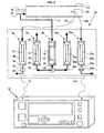
- la figure 1 est une vue schématique d'un dispositif de prélèvement selon l'invention dans une première configuration,
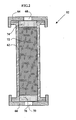
- la figure 2 est une vue en coupe transversale d'une cartouche utilisée dans le dispositif de la figure 1 et
- la figure 3 est une vue schématique du dispositif de prélèvement selon l'invention dans une autre configuration.
- FIG. 1 is a schematic view of a sampling device according to the invention in a first configuration,
- FIG. 2 is a cross-sectional view of a cartridge used in the device of FIG.
- Figure 3 is a schematic view of the sampling device according to the invention in another configuration.
Sur la figure 1, le dispositif de prélèvement des Hydrocarbures
Aromatiques Polycycliques (HAP) sous forme gazeuse contenus dans un
courant gazeux, comme des gaz d'échappement dilués d'un moteur à
combustion interne placé sur un banc à rouleaux, comprend une unité de
prélèvement 10 et une unité de contrôle 12 de l'unité 10.In FIG. 1, the Hydrocarbon sampling device
Polycyclic Aromatics (PAHs) in gaseous form contained in a
gaseous current, such as diluted engine exhaust
internal combustion placed on a dynamometer, includes a unit of
Ce dispositif de prélèvement est associé à un tunnel de prélèvement 14,
qui, dans la configuration "banc à rouleaux", est un tunnel de dilution plein
débit, dans lequel circulent les gaz d'échappement 16 issus du moteur à
combustion interne. Ce tunnel est alimenté en air de dilution, généralement de
l'air ambiant traité, par une conduite 18 de façon à obtenir, au niveau de la tête
de prélèvement 20 située à proximité de la sortie de ce tunnel, des gaz
d'échappement dilués répondant aux critères habituels de prélèvement
(température, teneur en eau, ...).This sampling device is associated with a
L'unité de prélèvement 10 comprend au moins un circuit de prélèvement
22 des HAP sous forme gazeuse, ici deux, comportant chacun deux voies de
prélèvement, une voie 24 pour prélever les HAP contenus dans l'air de dilution
et une voie 26 pour les HAP contenus dans les gaz d'échappement dilués ainsi
qu'une voie de filtration 28 de l'air de dilution.The
La voie de prélèvement 24 des HAP contenus dans l'air de dilution
comprend une unité de captation 30 comportant un support 32 dans lequel est
placé une cartouche de prélèvement amovible 34. La cartouche 34 est
traversée par de l'air de dilution préalablement filtré par la voie de filtration 28 et
amené par une conduite 36. Une conduite 38 permet d'évacuer l'air de dilution
après captation des HAP vers tous dispositifs connus.
La voie de filtration 28 comprend une unité de filtration 40 avec au moins
au moins un filtre 42 prévus pour capturer toutes les impuretés contenues dans
l'air de dilution qui traverse ce filtre. L'entrée de l'unité de filtration 40 est
raccordée par une conduite 44 à la conduite d'air de dilution 18 et la sortie de
cette unité est connectée par une conduite de sortie 46 à la conduite 36 menant
à l'entrée de l'unité de captation 30.
La voie de prélèvement 26 des HAP contenus dans les gaz
d'échappement dilués prélevés par la tête 20 comprend une unité de captation
48 avec un support 50 dans lequel est placé une cartouche de prélèvement
amovible 52. L'entrée de l'unité de captation 48 est raccordée par une conduite
54 à la tête de prélèvement 20 des gaz dilués et la sortie de cette unité est
connectée par une conduite 56 à tous moyens connus permettant d'évacuer et
de traiter les gaz d'échappement. Comme cela est connu en soi, les gaz
d'échappement circulant dans la conduite 54 sont déjà filtrés, de manière
avantageuse en aval de la tête 20, ce qui permet d'éliminer les impuretés qui
seraient susceptibles de colmater la cartouche de prélèvement 50.
De manière avantageuse, les supports 32, 50 et les cartouches 34, 52
peuvent être identiques pour les deux voies de prélèvement.The
The
The
Advantageously, the supports 32, 50 and the
Comme montré sur la figure 1, l'unité de prélèvement 10 comporte un
deuxième circuit de prélèvement 22a des HAP sous forme gazeuse comportant
deux voies de prélèvement 24a, 26a avec les mêmes composants que ceux
décrit avec le circuit 22. Bien entendu pour des raisons de simplification du
dispositif, la même voie de filtration 28 est utilisé pour le circuit 22a. Ceci
permet de réaliser deux prélèvements distincts successifs sans avoir à
interrompre ni le processus de prélèvement des HAP ni le fonctionnement du
moteur. Pour ce faire, il est prévu un moyen de vannage 58, tel qu'une vanne
trois voies, sur la conduite de sortie 46 de l'unité de filtration 40 qui permet de
mettre alternativement en communication soit la conduite 36 soit la conduite
36a. De même, les conduites 56 et 56a seront munies chacune d'un moyen de
vannage 60 et 60a, tel qu'une vanne deux voies de type rotatif ou autres,
permettant d'autoriser ou d'interrompre l'alimentation en gaz d'échappement
dilués dans les unités de captation 48 et 48a. Les vannes 60 et 60a sont
commandées d'une façon telle qu'ils ne soient jamais simultanément en
position d'ouverture ou de fermeture. Ainsi, lorsque le circuit de prélèvement 22
est opérationnel, la conduite 36 est en communication avec la conduite 46 par
action de la vanne 58, la vanne 60 est en position d'ouverture pour admettre les
gaz d'échappement dans la voie de prélèvement 26 et la vanne 60a est en
position de fermeture pour interdire la circulation de ces gaz dans la voie de
prélèvement 26a.As shown in FIG. 1, the
L'unité de commande/contrôle 12 permet, de manière connue en soi, de
paramétrer, de contrôler et/ou commander en permanence les conditions de
prélèvement, telles que le débit, la pression et la température des gaz
d'échappement et/ou d'air de dilution admis à l'entrée des unités de captation,
la durée des prélèvements, la mise en action de l'autre circuit de prélèvement
22a dans le cas d'une unité de prélèvement à deux circuits par action sur les
moyens de vannage 58, 60 et 60a. Cette unité commande également tous les
organes liés au fonctionnement de cette unité de prélèvement, comme les
pompes permettant la circulation du courant gazeux dans les voies de filtration
26, 28 et de prélèvement 24 de l'air de dilution.
Elle comprend également les alarmes sonores et/ou visuelles permettant
de déceler un éventuel dysfonctionnement ou un non-respect d'un paramètre
programmé.The control /
It also includes audible and / or visual alarms to detect any malfunction or failure to comply with a programmed parameter.
Durant le processus de prélèvement dans la configuration de la figure 1
correspondant à un véhicule utilisé sur un banc à rouleaux, seul le circuit de
prélèvement 22 est utilisé. Dans cette configuration, la vanne 60 est en position
d'ouverture, la vanne 58 est actionnée de manière à mettre en communication
la conduite de sortie 46 de la voie de filtration 28 avec la conduite d'entrée 36
de la voie de prélèvement 24 et la vanne 60a est en position de fermeture.
Les gaz d'échappement 16 issus du moteur à combustion interne de ce
véhicule sont mélangés dans le tunnel 14 avec de l'air de dilution amené par la
conduite 18. Une partie de cet air de dilution est envoyée, avant son
introduction dans le tunnel 14, par la conduite 44 dans l'unité de filtration 28 de
manière à le débarrasser des impuretés qu'il contient, comme les poussières.
Cet air de dilution filtré est ensuite envoyé dans l'unité de captation 30 des HAP
sous forme gazeuse et traverse la cartouche de prélèvement 34. Les HAP sous
forme gazeuse sont capturés par l'adsorbant contenu dans cette cartouche et
l'air de dilution dépourvu en grande partie des HAP est évacué à la sortie de
l'unité 30 par la conduite 38 vers tous moyens connus. Simultanément, les gaz
d'échappement dilués, préalablement filtrés, sont prélevés à proximité de la
sortie de ce tunnel 14 par la tête 20 et sont envoyés par la conduite 54 dans
l'unité de captation 48 des HAP sous forme gazeuse. Ces gaz traversent la
cartouche 52 et les HAP sous forme gazeuse présents dans ces gaz sont
retenus par l'adsorbant contenu dans cette cartouche. Les gaz d'échappement
débarrassés des HAP sont ensuite évacués par la conduite 56 vers tous
moyens connus pour leurs traitements avant rejet dans l'atmosphère.
Ainsi, durant ce processus, les HAP contenus à la fois dans l'air de dilution
et dans les gaz d'échappement dilués sont prélevés par deux cartouches
disposées en parallèles.During the sampling process in the configuration of Figure 1 corresponding to a vehicle used on a chassis dynamometer, only the
The
Thus, during this process, the PAHs contained in both the dilution air and the diluted exhaust gas are removed by two cartridges arranged in parallel.
Comme indiqué plus haut, il est possible d'effectuer deux prélèvements
successifs des HAP et cela sans interrompre le fonctionnement du moteur du
véhicule et de l'appareil de prélèvement. Après un premier prélèvement des
HAP effectué dans le circuit de prélèvement 22 par les cartouches des unités
de captation 30 et 48, il suffit d'arrêter ce prélèvement en agissant sur les
moyens de vannages 58 et 60 de façon à interrompre la circulation de l'air de
dilution et des gaz d'échappement dilués au travers des différentes voies de
filtration et de prélèvement. A la suite de cet arrêt, un deuxième prélèvement
des HAP contenus dans l'air de dilution et dans les gaz d'échappement dilués
peut être effectué dans le circuit de prélèvement 22a par les unités de captation
30a et 48a en agissant sur l'ouverture des moyens de vannages 58, 60a. Dans
cette configuration, la voie de filtration 28 utilisée pour le premier prélèvement
sera avantageusement utilisé également pour réaliser le deuxième
prélèvement.As mentioned above, it is possible to take two samples
PAHs without interrupting the operation of the engine of the
vehicle and the sampling device. After a first sampling of
PAH performed in the
Une fois que le prélèvement des HAP est terminé, les cartouches 34, 52
sont démontées de leurs supports 32, 50. Ces cartouches sont ensuite traitées
pour en extraire les HAP grâce à un solvant, tel que du dichlorométhane ou du
toluène. Avantageusement, cette extraction est réalisée en utilisant un système
d'extraction par solvant accélérée (ASE) qui a pour avantage d'employer une
très faible quantité de solvant, ce qui permet d'éviter une reconcentration de
l'adsorbant. De plus, le système d'extraction est adapté à la configuration des
cartouches de manière à éviter tout démontage de leurs éléments constitutifs
ou tout transfert de l'adsorbant qu'elles contiennent.Once the removal of PAHs is complete,
Les HAP extraits pour chaque cartouche sont analysés par tous moyens, en particulier par le couplage d'une chromatographie avec une spectrométrie de masse ou par une chromatographie liquide haute performance, de façon à identifier et quantifier les HAP contenus dans l'air de dilution et dans les gaz d'échappement dilués.The extracted PAHs for each cartridge are analyzed by any means, in particular by the coupling of a chromatography with a spectrometry of mass or by high performance liquid chromatography, so that identify and quantify PAHs in dilution air and gases diluted exhaust.
Après ces analyses, l'identification et la quantification des HAP sous forme gazeuse finalement contenus dans les gaz d'échappement sont déterminées après déduction des HAP identifiés et quantifiés de l'air de dilution.After these analyzes, the identification and quantification of PAHs in the form of gas finally contained in the exhaust gases are determined after deduction of identified and quantified PAHs from the dilution air.
Avantageusement, ce dispositif de prélèvement sera associé à tous
dispositifs connus permettant de prélever, identifier et quantifier les HAP
condensés sur la forme particulaire des gaz d'échappement.
Ainsi, la présente invention permet de compléter la connaissance des HAP
condensés sur la phase particulaire contenus dans les gaz d'échappement par
l'identification et la quantification des HAP sous forme gazeuse.Advantageously, this sampling device will be associated with all known devices for taking, identifying and quantifying PAHs condensed on the particulate form of the exhaust gas.
Thus, the present invention makes it possible to complete the knowledge of condensed PAHs on the particulate phase contained in the exhaust gases by the identification and quantification of PAHs in gaseous form.
La figure 2 montre un exemple de réalisation de la cartouche de
prélèvement 52 qui est utilisée dans l'unité de captation 48 des HAP contenus
dans les gaz d'échappement. Avantageusement, ce même type de cartouche
peut être utilisé dans l'unité de captation 30 des HAP de l'air de dilution ainsi
que dans les unités de captation 30a et 48a. Comme déjà évoqué, ces types de
cartouche permettent une adaptation rapide, simple et sans manipulation de
l'absorbant par le système d'extraction mis en oeuvre. FIG. 2 shows an exemplary embodiment of the cartridge of
sampling 52 which is used in the
Cette cartouche 52 comprend un corps tubulaire sensiblement cylindrique
62 fermé à ses extrémités par deux couvercles amovibles 64, 66. Chaque
couvercle est muni d'un alésage 68, 70 permettant de mettre en communication
l'intérieur du corps 62 avec respectivement l'arrivée de gaz d'échappement par
la conduite 54 et l'évacuation de ces gaz par la conduite 56. Les couvercles
sont fixés à étanchéité sur le corps 62 par tous moyens connus, tels que par
vissage. Le corps contient dans son volume creux un adsorbant 72 constitué de
résine à base de polymères poreux, plus connu sous le nom d'Amberlite. A titre
d'exemple, l'adsorbant est du type commercialisé sous le vocable XAD2
Supelpak et comprend une résine avec une matrice de type
styrène/divinylbenzène polyaromatique. Un lit de laine de quartz 74, 76 est
disposé entre chaque couvercle 64, 66 et l'adsorbant 72 de manière à
immobiliser cet adsorbant à l'intérieur du corps 62 tout en ne pénalisant pas la
circulation des gaz d'échappement au travers de ces lits.
Avantageusement, les alésages 68, 70 sont configurés d'une manière telle
qu'ils permettent d'être obturés par tous moyens connus, tels que des bouchons
à joint torique, après le démontage de la cartouche hors de son support.This
Advantageously, the
On se réfère maintenant à la figure 3 qui montre le dispositif de
prélèvement dans une autre configuration, dite banc moteur.
Dans cette configuration, l'unité de prélèvement 10 comprend également
deux circuits de prélèvement 22 et 22a et est associée à un microtunnel 14 qui
contient un air de dilution qui est déjà purifié et filtré.
Chaque circuit de prélèvement comprend une voie de filtration 78 des gaz
d'échappement connectée à une voie de prélèvement 80 des HAP sous forme
gazeuse contenus dans les gaz d'échappement filtrés.
La voie de filtration 78 comprend une unité de filtration 40 semblable à
celle décrite précédemment avec au moins un filtre 42 prévus pour capturer
toutes les impuretés contenues dans les gaz d'échappement dilués qui
traversent ce filtre, une conduite d'entrée 82 des gaz d'échappement amenant
ces gaz de la tête 20 à l'entrée de l'unité 40 et une conduite de sortie 84 des
gaz d'échappement filtrés. La conduite d'entrée porte un moyen de vannage 86,
sous la forme d'une vanne, permettant d'autoriser ou d'interdire l'arrivée des
gaz d'échappement dilués dans cette unité de filtration 40.
La voie de prélèvement 80 comprend également une unité de captation
48, semblable à l'unité de captation de la figure 1, avec un support 50 portant
une cartouche de prélèvement amovible 52. L'entrée de l'unité de captation 48
est connectée à la conduite 84 de sortie des gaz filtrés et la sortie de cette unité
est reliée à une conduite 88 pour évacuer les gaz d'échappement dilués
dépourvus de HAP.
De manière préférentielle, la conduite 84 peut comprendre une conduite
en dérivation 90 permettant d'évacuer une partie des gaz d'échappement dilués
et filtrés, notamment vers le système de contrôle du microtunnel (non
représenté). Dans ce cas, il est prévu un moyen de vannage 92, comme une
vanne trois voies, permettant de mettre en communication sélectivement la
conduite 90 ou la conduite 90a avec le système de contrôle du microtunnel.Referring now to Figure 3 which shows the sampling device in another configuration, said engine bench.
In this configuration, the
Each sampling circuit comprises an exhaust
The
The
Preferably, the
En fonctionnement, tel qu'illustré à titre d'exemple sur la figure 3, seul le
circuit de prélèvement 22 est utilisé. Dans cette configuration, la vanne 86 est
en position d'ouverture de façon à mettre en communication, grâce à la
conduite 82, les gaz prélevés par la tête 20 avec l'unité de filtration 40 et la
vanne 92 est dans une position telle que la conduite 90 permet d'évacuer une
partie des gaz d'échappement après filtration. Ces gaz dilués traversent l'unité
de filtration 40 de manière à être débarrassés des impuretés qu'ils contiennent.
Ces gaz d'échappement filtrés sont ensuite envoyés dans l'unité de captation
48 des HAP sous forme gazeuse par la conduite 84 en ayant au préalable
traversés la cartouche de prélèvement 52 et également dans la conduite 90.
Les HAP sous forme gazeuse sont recueillis par l'adsorbant contenu dans cette
cartouche et les gaz d'échappement dépourvus de HAP sont évacués par la
conduite 88 vers tous moyens connus.
Comme déjà indiqué plus haut dans la configuration de la figure 1, il est
possible d'effectuer deux prélèvements successifs des HAP sans avoir la
nécessité d'interrompre le fonctionnement du moteur du véhicule et du dispositif
de prélèvement. Ainsi, après le premier prélèvement des HAP effectué dans le
circuit de prélèvement 22 par l'unité de captation 48, il suffit d'interrompre la
circulation des gaz d'échappement dans la voie de filtration par fermeture de la
vanne 86. A la suite de cette fermeture, la vanne 92 est actionnée pour
permettre la circulation des gaz filtrés dans la conduite 90a et la vanne 86a peut
être ouverte pour permettre la circulation des gaz d'échappement dilués dans la
voie de filtration 78a ainsi que dans la voie de prélèvement 80a.
Une fois que les prélèvements des HAP sont terminés, la cartouche 52 est
démontée de son support 50 pour être traitée dans le but d'en extraire, identifier
et quantifier les HAP comme cela a été décrit pour la figure 1.In operation, as illustrated by way of example in FIG. 3, only the
As already indicated above in the configuration of Figure 1, it is possible to perform two successive sampling PAH without the need to interrupt the operation of the vehicle engine and the sampling device. Thus, after the first sampling of the PAHs carried out in the
Once the PAH samples are complete, the
Egalement, ce dispositif de prélèvement sera associé à tous dispositifs connus permettant de prélever, identifier et quantifier les HAP présents sous forme condensée dans la phase particulaire de ces gaz.Also, this sampling device will be associated with all devices known to collect, identify and quantify the PAH present under condensed form in the particulate phase of these gases.
Claims (16)
Applications Claiming Priority (2)
| Application Number | Priority Date | Filing Date | Title |
|---|---|---|---|
| FR0313397A FR2862386B1 (en) | 2003-11-14 | 2003-11-14 | METHOD AND DEVICE FOR REMOVING GASEOUS COMPOUNDS FROM A GAS CURRENT, IN PARTICULAR IN EXHAUST GASES DILUTED FROM AN INTERNAL COMBUSTION ENGINE |
| FR0313397 | 2003-11-14 |
Publications (1)
| Publication Number | Publication Date |
|---|---|
| EP1531325A1 true EP1531325A1 (en) | 2005-05-18 |
Family
ID=34429997
Family Applications (1)
| Application Number | Title | Priority Date | Filing Date |
|---|---|---|---|
| EP04292506A Withdrawn EP1531325A1 (en) | 2003-11-14 | 2004-10-21 | Method and apparatus for sampling gaseous components in a gaseous stream, in particular in diluted exhaust gases of an internal combustion engine. |
Country Status (3)
| Country | Link |
|---|---|
| US (1) | US20050109128A1 (en) |
| EP (1) | EP1531325A1 (en) |
| FR (1) | FR2862386B1 (en) |
Families Citing this family (6)
| Publication number | Priority date | Publication date | Assignee | Title |
|---|---|---|---|---|
| US7343782B2 (en) * | 2006-04-10 | 2008-03-18 | Northrop Grumman Corporation | System and method for performing quantifiable release spore testing on bioaerosol detection technologies |
| US8181543B2 (en) * | 2006-09-15 | 2012-05-22 | Avl North America Inc. | CVS system sample water vapor management |
| US8505395B2 (en) * | 2009-08-25 | 2013-08-13 | Caterpillar Inc. | Dilution system test apparatus with added capability and method of operating same |
| JP5492001B2 (en) * | 2010-07-23 | 2014-05-14 | 株式会社堀場製作所 | Exhaust gas analysis system |
| US9297726B2 (en) | 2012-05-23 | 2016-03-29 | Avl Test Systems, Inc. | Exhaust sampling system and method for water vapor management |
| US9518897B2 (en) | 2012-05-29 | 2016-12-13 | Avl Test Systems, Inc. | Intelligent bag filling for exhaust sampling system |
Citations (7)
| Publication number | Priority date | Publication date | Assignee | Title |
|---|---|---|---|---|
| WO1994001753A1 (en) * | 1992-07-13 | 1994-01-20 | The Broken Hill Proprietary Company Limited | Sampling device for airborne particulate or vapour emissions |
| EP0582840A1 (en) * | 1992-07-24 | 1994-02-16 | AUSTRIAN ENERGY & ENVIRONMENT SGP/WAAGNER-BIRO GmbH | Method for measuring pollutants in gases |
| US5493923A (en) | 1992-02-26 | 1996-02-27 | Gfa Gesellschaft Zur Arbeitsplatz-Und Umweltanalytik Mbh | Process and device for taking samples from waste gases |
| US6134942A (en) * | 1998-06-26 | 2000-10-24 | Institut Francais Du Petrole | System for sampling specific pollutants contained in diluted exhaust gases from thermal engines |
| EP1243909A1 (en) * | 2001-03-19 | 2002-09-25 | Leces | Sampling line for taking samples of hot gaseous effluents in diffuse emission |
| DE10128632A1 (en) * | 2001-06-13 | 2003-01-02 | Karlsruhe Forschzent | Long-term sampling system |
| US20030136177A1 (en) | 2000-05-25 | 2003-07-24 | Fredrick Hendren | Emission sampling apparatus and method |
Family Cites Families (10)
| Publication number | Priority date | Publication date | Assignee | Title |
|---|---|---|---|---|
| US3406562A (en) * | 1966-01-14 | 1968-10-22 | Gen Motors Corp | On-line exhaust data analysis system |
| US5058440A (en) * | 1990-09-04 | 1991-10-22 | Caterpillar Inc. | Gas sampling device and dilution tunnel used therewith |
| US5843311A (en) * | 1994-06-14 | 1998-12-01 | Dionex Corporation | Accelerated solvent extraction method |
| US5846831A (en) * | 1997-04-01 | 1998-12-08 | Horiba Instuments, Inc. | Methods and systems for controlling flow of a diluted sample and determining pollutants based on water content in engine exhaust emissions |
| US5846292A (en) * | 1997-05-06 | 1998-12-08 | Board Of Supervisors At Louisiana State University & Agricultural & Mechanical College | Chromatograph with column extraction |
| FR2780506B1 (en) * | 1998-06-25 | 2000-08-25 | Inst Francais Du Petrole | METHOD AND UNIT FOR SAMPLING ALDEHYDES AND KETONES CONTAINED IN EXHAUST GASES |
| US7029506B2 (en) * | 2000-04-14 | 2006-04-18 | Jordan Frederick L | Organic cetane improver |
| US20030084658A1 (en) * | 2000-06-20 | 2003-05-08 | Brown Kevin F | Process for reducing pollutants from the exhaust of a diesel engine using a water diesel fuel in combination with exhaust after-treatments |
| US20030089030A1 (en) * | 2001-03-22 | 2003-05-15 | Jordan Frederick L. | Method and composition for using organic, plant-derived, oil-extracted materials in resid fuels for reduced emissions |
| US6823268B2 (en) * | 2002-02-04 | 2004-11-23 | Avl North America Inc. | Engine exhaust emissions measurement correction |
-
2003
- 2003-11-14 FR FR0313397A patent/FR2862386B1/en not_active Expired - Fee Related
-
2004
- 2004-10-21 EP EP04292506A patent/EP1531325A1/en not_active Withdrawn
- 2004-11-12 US US10/985,947 patent/US20050109128A1/en not_active Abandoned
Patent Citations (7)
| Publication number | Priority date | Publication date | Assignee | Title |
|---|---|---|---|---|
| US5493923A (en) | 1992-02-26 | 1996-02-27 | Gfa Gesellschaft Zur Arbeitsplatz-Und Umweltanalytik Mbh | Process and device for taking samples from waste gases |
| WO1994001753A1 (en) * | 1992-07-13 | 1994-01-20 | The Broken Hill Proprietary Company Limited | Sampling device for airborne particulate or vapour emissions |
| EP0582840A1 (en) * | 1992-07-24 | 1994-02-16 | AUSTRIAN ENERGY & ENVIRONMENT SGP/WAAGNER-BIRO GmbH | Method for measuring pollutants in gases |
| US6134942A (en) * | 1998-06-26 | 2000-10-24 | Institut Francais Du Petrole | System for sampling specific pollutants contained in diluted exhaust gases from thermal engines |
| US20030136177A1 (en) | 2000-05-25 | 2003-07-24 | Fredrick Hendren | Emission sampling apparatus and method |
| EP1243909A1 (en) * | 2001-03-19 | 2002-09-25 | Leces | Sampling line for taking samples of hot gaseous effluents in diffuse emission |
| DE10128632A1 (en) * | 2001-06-13 | 2003-01-02 | Karlsruhe Forschzent | Long-term sampling system |
Also Published As
| Publication number | Publication date |
|---|---|
| US20050109128A1 (en) | 2005-05-26 |
| FR2862386B1 (en) | 2006-03-03 |
| FR2862386A1 (en) | 2005-05-20 |
Similar Documents
| Publication | Publication Date | Title |
|---|---|---|
| US8196479B2 (en) | Portable multi-tube air sampler unit | |
| US5468643A (en) | Switching valve system for direct biological sample injection for LC analysis | |
| EP0973032B1 (en) | System for sampling specific pollutants in diluted thermal machine exhaust gases | |
| JP2007218916A (en) | Method and device for measuring permeation | |
| JPH08512409A (en) | Instrument for measuring non-methane organic gases in gas samples | |
| FR2475119A1 (en) | DEVICE FOR ADJUSTING THE EXHAUST GAS EMISSION FOR A DIESEL ENGINE | |
| JP2013513816A (en) | Helium recovery system and method for gas chromatograph | |
| EP1531325A1 (en) | Method and apparatus for sampling gaseous components in a gaseous stream, in particular in diluted exhaust gases of an internal combustion engine. | |
| FR2988620A1 (en) | DEVICE AND METHOD FOR EXTRACTING COMPOUNDS CONTAINED IN A LIQUID SAMPLE FOR ANALYSIS | |
| JPH11211630A (en) | Gas sample collecting device and its use method | |
| CA2296194C (en) | Integrated analysis process and system for hydrocarbon characterization by distillation simulation | |
| JP2001194354A (en) | Method and apparatus for analyzing sample by gas chromatography | |
| FR2932271A1 (en) | DEVICE FOR MEASURING THE PURITY OF ULTRAPURE WATER | |
| FR2932270A1 (en) | METHOD AND DEVICE FOR MEASURING THE PURITY OF ULTRAPURATED WATER | |
| EP1574851A2 (en) | Multiparallel compound separation device | |
| FR2919055A1 (en) | METHOD AND DEVICE FOR DETECTING AND QUANTIFYING A CHEMICAL COMPOUND IN A FLUID CURRENT | |
| EP2380646A1 (en) | Apparatus and process to characterize dissolved gas in liquid | |
| WO2008061872A1 (en) | Test bench for exhaust gas analysis and method for using the same | |
| JP3843977B2 (en) | Sample extraction device for analysis of dioxins | |
| EP1409320B1 (en) | Hydraulic braking circuit with filtration means | |
| WO2006056715A2 (en) | Complex liquid treatment method and device for implementing same | |
| JP4258409B2 (en) | Online compound analyzer | |
| JP2002181673A (en) | Pretreatment method in concentration measurement of pcb and sampling device and refining device used in this pretreatment | |
| JPH08262007A (en) | Ultramicroamount organic substance extraction system | |
| JP2003307474A (en) | Analytical sample sampling apparatus for dioxins |
Legal Events
| Date | Code | Title | Description |
|---|---|---|---|
| PUAI | Public reference made under article 153(3) epc to a published international application that has entered the european phase |
Free format text: ORIGINAL CODE: 0009012 |
|
| AK | Designated contracting states |
Kind code of ref document: A1 Designated state(s): AT BE BG CH CY CZ DE DK EE ES FI FR GB GR HU IE IT LI LU MC NL PL PT RO SE SI SK TR |
|
| AX | Request for extension of the european patent |
Extension state: AL HR LT LV MK |
|
| 17P | Request for examination filed |
Effective date: 20051118 |
|
| AKX | Designation fees paid |
Designated state(s): AT CH DE GB LI NL |
|
| 17Q | First examination report despatched |
Effective date: 20101116 |
|
| R17C | First examination report despatched (corrected) |
Effective date: 20101118 |
|
| STAA | Information on the status of an ep patent application or granted ep patent |
Free format text: STATUS: THE APPLICATION IS DEEMED TO BE WITHDRAWN |
|
| 18D | Application deemed to be withdrawn |
Effective date: 20130503 |