BACKGROUND OF THE INVENTION
The present invention relates to a waterproof type
lead composed of a terminal having an electrical contact
section, a core wire crimping section and an insulating
coating crimping section, an electric wire having plural core
wires crimped with the core wire crimping section and an
insulating coating crimped with the insulating coating
crimping section, and a heat-shrinkable tube that covers the
core wire crimping section after crimping and has an adhesive
applied to the internal circumference thereof, a method of
making the waterproof type lead, and a jig for making the
waterproof type lead.
In order to connect a terminal having an electrical
contact section, a core wire crimping section and an
insulating coating crimping section to an electric wire
having plural core wires entirely coated with an insulating
coating, the electric wire is stripped of the insulating
coating at an end part thereof to expose the plural core
wires, and then, the exposed core wires are crimped with the
core wire crimping section, and the leading end of the
remaining insulating coating is crimped with the insulating
coating crimping section.
If such a terminal connected to the electric wire
(referred to as a lead, hereinafter) is used at a place where
intrusion of water, such as rainwater, is likely to occur,
measures for protecting the lead from water have to be taken.
Known conventional waterproof type leads include one having
the leading end part of the core wires crimped with the core
wire crimping section soldered and the trailing end of the
crimped part of the core wires covered with a shrinkable
tube, and one having a tubular terminal that surrounds the
part of the core wires crimped with the core wire crimping
section to shield the core wires from the outside (see
Japanese Patent Laid-Open No. 2001-110464, for example). In
addition, there is known a waterproof type lead in which core
wires crimped with the core wire crimping section are covered
with a heat-shrinkable tube having an adhesive applied to the
internal surface thereof (see Japanese Patent Laid-Open No.
2000-285983 and Japanese Patent Laid-Open No. 2000-182688,
for example).
However, the waterproof type lead that involves
soldering described in Japanese Patent Laid-Open No. 2001-110464
requires two steps, that is, a step of attaching the
shrinkable tube and a step of soldering, and thus, has a
problem that the workability is bad and the manufacturing
costs are high. Furthermore, the waterproof type lead that
has a tubular terminal described in Japanese Patent Laid-Open
No. 2001-110464 has a problem that the tubular terminal is
not easy to fabricate and the manufacturing costs are high,
although the workability is good. Besides, the waterproof
type lead described in Japanese Patent Laid-Open No. 2000-285983
is manufactured by heating the heat-shrinkable tube to
make the adhesive on the internal surface thereof molten,
thereby coating the circumference of the bundle of plural
core wires with the adhesive. However, intrusion of water
into the electric wire often occurs at the leading end of the
core wires through clearances between adjacent core wires,
and thus, coating only the circumference of the bundle of
core wires does not suffice for waterproofing.
SUMMARY OF THE INVENTION
The present invention has been made in view of the
above circumstances and provides a waterproof type lead for
which sufficient measures for waterproofing are taken at low
cost, a method of making a waterproof type lead at low cost,
and a jig for making a waterproof type lead at low cost.
The present invention provides a waterproof type
lead including:
in which clearances between adjacent core wires at a
leading end of the plurality of core wires are sealed with
the adhesive.
In the waterproof type lead according to the
present invention, the adhesive flows into the clearances
between adjacent core wires at the leading end of the core
wires, and the clearances are sealed with the adhesive.
Thus, sufficient measures for waterproofing are taken. In
addition, since the adhesive sealing the clearances is
previously applied to the internal circumference of the heat-shrinkable
tube, the soldering step described above
concerning the prior art is not required. Therefore, the
manufacturing cost can be reduced compared with the
waterproof type lead described in Japanese Patent Laid-Open
No. 2001-110464.
The present invention provides a method of making a
waterproof type lead, including the steps of:
According to the method of making a waterproof type
lead according to the present invention, the adhesive having
been molten by heating of the heat-shrinkable tube and flowed
out of the heat-shrinkable tube is stopped by the adhesive-flow
stopper section of the jig, and the leading end of the
wire cores are sealed with the stopped adhesive. In the
method of making a waterproof type lead according to the
present invention, the sealing may be achieved by covering
the leading end surface of the core wires with the adhesive
or by letting the adhesive flow into the clearances between
adjacent core wires at the leading end of the core wires. In
addition, according to this manufacturing method, the
adhesive is prevented from coming into contact with the
electrical contact section of the terminal, and thus, the
waterproof type lead manufactured by this method can provide
a good electrical contact. Furthermore, according to the
method of making a waterproof type lead according to the
present invention, measures for waterproofing can be taken
simply by attaching the jig to the terminal and heating the
heat-shrinkable tube, and thus, the manufacturing costs can
be reduced. Furthermore, according to this manufacturing
method, there is no need to prepare a terminal specially
configured for the purpose of waterproofing or preventing the
contact of the adhesive with the electrical contact section,
and a terminal having an ordinary configuration will suffice.
Thus, the variety of terminals does not increase, so that the
commodity management can be facilitated.
The present invention provides a jig for making a
waterproof type lead by being attached to the waterproof type
lead, the waterproof type lead including a terminal having an
electrical contact section, a core wire crimping section and
an insulating coating crimping section, an electric wire
having a plurality of core wires crimped with the core wire
crimping section and an insulating coating crimped with the
insulating coating crimping section, and a heat-shrinkable
tube that covers the core wire crimping section after
crimping and has an unmolten adhesive applied to the internal
circumference thereof, the jig including:
In the jig for making a waterproof type lead
according to the present invention, the adhesive having
flowed out of the heat-shrinkable tube is stopped by the
adhesive-flow stopper section. Therefore, the adhesive is
prevented from coming into contact with the electrical
contact section of the terminal, and thus, the waterproof
type lead manufactured using this jig can provide a good
electrical contact. The leading end of the core wires is
sealed with the adhesive in such a manner that the stopped
adhesive covers the leading end surface of the core wires and
is set there, or the stopped adhesive flows into the
clearances between adjacent core wires at the leading end of
the core wires and is set there. Therefore, if the jig
according to the present invention is used for making the
waterproof type lead, measures for waterproofing can be taken
simply by heating the heat-shrinkable tube, and thus, the
waterproof type lead can be manufactured at low costs.
In addition, in the jig for making a waterproof
type lead according to the present invention, the adhesive-flow
stopper section preferably has a coating layer of
tetrafluoroethylene resin.
This facilitates detaching the jig from the
waterproof type lead after the adhesive is set.
In addition, the jig for making a waterproof type
lead according to the present invention preferably further
has a tube pressing section that is provided on the leading
end of the other of the grip sections and presses the heat-shrinkable
tube against the one of the grip sections.
If the molten adhesive functions as a lubricant and
the heat-shrinkable tube moves (that is, a milk off
phenomenon) or the heat-shrinkable tube shrinks along the
length (that is, a shrink-back phenomenon), there is a
possibility that the heat-shrinkable tube moves away from the
leading end of the core wires, and the molten adhesive does
not reach the adhesive-flow stopper section. However,
according to the implementation described above, since the
heat-shrinkable tube is held by the tube pressing section,
the milk-off phenomenon and the shrink-back phenomenon are
prevented. Thus, using the jig according to this
implementation can assure that the molten adhesive reaches
the adhesive-flow stopper section.
Here, the electrical contact section of the
terminal described herein may be a male contact section, such
as a ring contact section and a tab contact section, or a
female contact section, such as a receptacle contact section.
Furthermore, the adhesive described herein may be integral
with the heat-shrinkable tube or separate therefrom.
Furthermore, the heat-shrinkable tube described herein may
cover the insulating coating crimping section after crimping
in addition to the core wire crimping section after crimping.
According to the present invention, there can be
provided a waterproof type lead for which sufficient measures
for waterproofing are taken at low costs, a method of making
a waterproof type lead at low costs, and a jig used for
making a waterproof type lead at low costs.
BRIEF DESCRIPTION OF THE DRAWINGS
Fig. 1 is a plan view of one of paired LA
terminals;
Fig. 2 is a side view of the paired LA terminal
shown in Fig. 1;
Fig. 3 is a plan view of a paired LA terminal to be
paired with the paired LA terminal shown in Fig. 1;
Fig. 4 is a side view of the paired LA terminal
shown in Fig. 3;
Fig. 5 schematically shows the paired LA terminal
shown in Fig. 1 and the paired LA terminal shown in Fig. 3
that are mated with each other;
Fig. 6 is a schematic cross-sectional view of a
waterproof type lead shown in Fig. 5 taken along the line X-X;
Fig. 7 is a flowchart showing a method of making
the waterproof type lead shown in Fig. 5;
Fig. 8 is a plan view of a jig used in step S4 in
Fig. 7;
Fig. 9 is a side view of the jig shown in Fig. 8;
Fig. 10 is a bottom view of the jig shown in Fig.
8; and
Fig. 11 is a side view of the waterproof type lead
shown in Fig. 5 attached to the jig shown in Fig. 8.
DETAILED DESCRIPTION OF THE INVENTION
In the following, embodiments of the present
invention will be described with reference to the drawings.
As an example, a waterproof type lead having paired
LA terminals will be described herein.
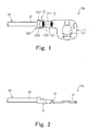
Fig. 1 is a plan view of one of paired LA
terminals, and Fig. 2 is a side view of the paired LA
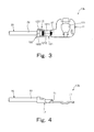
terminal shown in Fig. 1. Fig. 3 is a plan view of a paired
LA terminal to be paired with the paired LA terminal shown in
Fig. 1, and Fig. 4 is a side view of the paired LA terminal
shown in Fig. 3.
Paired LA terminals 10a and 10b shown in Figs. 1
and 3, respectively, are each connected to an electric wire
20 having plural core wires 21 coated with an insulating
coating 22 and each have an electrical contact section 11 and
a substrate section 12. The electrical contact sections 11
of the paired LA terminals 10a and 10b can be mated with each
other and are provided at the front ends of the paired LA
terminals 10a and 10b. The electrical contact section 11 has
an insertion opening 111. A bolt (not shown) is inserted
into the insertion opening 111, and the paired LA terminals
10a and 10b are connected to a battery or the like in an
engine room of an automobile.
The substrate section 12 is provided at the rear
end of the electrical contact section 11 and has a core wire
crimping section 121 and an insulating coating crimping
section 122. The core wire crimping section 121 is composed
of a pair of crimping pieces 1211 and 1212 extending from the
both sides of the front end of the substrate section 12.
And, the core wire crimping section 121 crimps, with the pair
of crimping pieces 1211 and 1212, a bundle of plural core
wires 21 that are exposed by stripping the electric wire 20
of the insulating coating 22 at the leading end thereof. The
insulating coating crimping section 122 is composed of a pair
of crimping pieces 1221 and 1222 extending from the both
sides of the rear end of the substrate section 12. And, the
insulating coating crimping section 122 crimps, with the pair
of crimping pieces 1221 and 1222, the leading end part of the
insulating coating 22 remaining after the stripping of the
insulating coating 22 from the leading end of the electric
wire 20. The drawings show the core wire crimping section
121 crimping the core wires 21 and the insulating coating
crimping section 122 crimping the insulating coating 22. The
leading end of the plural core wires crimped by the core wire
crimping section 121 protrudes from the core wire crimping
section 121 toward the electrical contact section 11.
Fig. 5 shows the paired LA terminal shown in Fig. 1
and the paired LA terminal shown in Fig. 3 mated with each
other.
Referring to Fig. 5, the paired LA terminals 10a
and 10b connected to the electric wires 20 shown in Figs. 1
and 3, respectively, each have the core wire crimping section
and the insulating coating crimping section covered with one
heat-shrinkable tube 30, and the electrical contact sections
11 thereof are mated with each other. The waterproof type
lead according to the present invention is composed of the
terminal, the electric wire having the plural core wires
crimped with the core wire crimping section and the
insulating coating crimped with the insulating coating
crimping section, and the heat-shrinkable tube covering the
core wire crimping section after crimping, and Fig. 5 shows
two such waterproof type lead 1a and 1b mated with each
other. A hot-melt adhesive is applied to an internal surface
of the heat-shrinkable tube 30 shown in Fig. 5. The heat-shrinkable
tube 30 is heated, and the adhesive on the
internal surface is molten. The heat-shrinkable tube 30
shown in Fig. 5 is one after being heated, and there is also
shown adhesive 31 that flows from the internal surface of
each heat-shrinkable tube 30 out of the end thereof and is
set there.
Fig. 6 is a schematic cross-sectional view of the
waterproof type lead taken along the line X-X in Fig. 5.
Fig. 6 shows a lateral cross section of the leading
end part of the core wires 21 of the waterproof type lead 1a
shown in Fig. 5 that protrude from the core wire crimping
section 121. The expression "vertical direction of the
waterproof type lead 1a" in the following description can
refer to the vertical direction in Fig. 6.
The heat-shrinkable tube 30 constitutes the
outermost layer of the waterproof type lead 1a shown in Fig.
6. The heat-shrinkable tube 30 shrinks by heat in radial
direction to stick to the paired crimping pieces 1211 and
1212 of the core wire crimping section 121. On the internal
surface of the shrunk heat-shrinkable tube 30, the adhesive
31 is shown that has not flowed out and been set. In
addition, the adhesive 31 from the internal surface of the
heat-shrinkable tube 30 flows into clearances S between
adjacent core wires 21 protruding from the core wire crimping
section 121, and thus, the clearances S are sealed with the
adhesive 31. Such clearances S would otherwise make the
electric wire vulnerable to water intrusion. However, in the
waterproof type lead 1a shown in Fig. 6, the clearances S are
sealed with the adhesive, and the waterproof type lead 1a is
protected from water with reliability. In this way,
sufficient measures for waterproofing are taken.
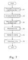
Fig. 7 is a flowchart showing a method of making
the waterproof type lead shown in Fig. 5.
Manufacture of the waterproof type lead 1a shown in
Fig. 5 begins with fabrication of the paired LA terminal 10a
shown in Fig. 1 by press working and preparation of the
electric wire 20 containing plural core wires 21 entirely
coated with the insulating coating 22 (step S1). In this
step, the heat-shrinkable tube 30 having not shrunk yet in
which an adhesive applied to the internal surface thereof is
provided on the electric wire 20.
Then, using a crimping device (not shown), a
leading end part of the electric wire 20 prepared in step S1
is stripped of the insulating coating 22 to expose the plural
core wires 21, the bundle of exposed core wires 21 is fitted
into the core wire crimping section 121 of the fabricated
paired LA terminal 10a with a core-wire crimper and a core-wire
anvil, and a leading end part of the remaining
insulating coating 22 is fitted into the insulating coating
crimping section 122 of the paired LA terminal 10a with an
insulating-coating crimper and an insulating-coating anvil
(step S2). In this way, the paired LA terminal 10a is
connected to the electric wire 20.
Then, the LA terminal 10a is coated with the heat-shrinkable
tube yet to be shrunk over a sufficient length
including the insulating coating crimping section in which
the insulating coating is fitted (step S3).
Then, a jig is attached to the paired LA terminal
10a that is connected to the electric wire and has the core
wire crimping section and the periphery thereof covered with
the heat-shrinkable tube (step S4).
Now, suspending the description of Fig. 7, the jig
used in step S4 will be described with reference to Figs. 8
to 10.
Fig. 8 is a plan view of the jig used in step S4 in
Fig. 7, Fig. 9 is a side view of the jig shown in Fig. 8, and
Fig. 10 is a bottom view of the jig shown in Fig. 8. The
side view in Fig. 9 shows the jig in Fig. 8 viewed from the
bottom side of Fig. 8.
A jig 40 shown in Fig. 8 is formed from one metal
plate by die cutting and bending and has a pair of grip
sections 41. The pair of grip sections 41 includes an upper
grip section 411 and a lower grip section 412. As shown in
Fig. 9, one end of each grip section is a free end, and the
other end thereof is connected to the other end of the other
grip section. Here, the free end side is referred to as a
tip end side. The paired grip sections 41 are to grip the
waterproof type leads 1a and 1b shown in Fig. 5 from the top
and the bottom thereof.
The upper grip section 411 has two through holes
4111 as shown in Fig. 8. Bolts are inserted into the through
holes 4111 for attaching the jig 40 to a jig handle section
(not shown). In addition, the tip end of the upper grip
section 411 is bent upward approximately 90 degrees to form
an adhesive-flow stopper section 4112, as shown in Fig. 9.
The adhesive-flow stopper section 4112 is formed along the
entire width of the jig 40 (that is, in the vertical
direction in Fig. 8) and has a coating layer 4112a of
tetrafluoroethylene resin (see Fig. 9). The waterproof type
leads 1a and 1b shown in Fig. 5 are attached to the jig 40 by
inserting them between the paired grip sections 41 from one
lateral end of the jig 40 (that is, from the upper side in
Fig. 8) and sliding them along the width of the jig. To
facilitate insertion of the waterproof type leads 1a and 1b,
the adhesive-flow stopper section 4112 is curved rearward at
the lateral end for receiving the waterproof type leads 1a
and 1b to form an introduction section 4112b. In addition,
the upper grip section 411 has a recess section 4113 toward
the lower grip section 412 between the through holes 4111 and
the adhesive-flow stopper section 4112 along the entire width
of the jig 40.
The lower grip section 412 has a cutout hole 4122
in the middle thereof. In addition, as shown in Fig. 9, the
tip end of the lower grip section 412 is bent approximately
90 degrees toward the upper grip section 411 and further bent
toward the front of the jig to form a tube pressing section
4121 having a substantially L-shaped profile. The
substantially L-shaped tube pressing section 4121 is also
provided along the entire width of the jig 40 and has a
coating layer 4121a of tetrafluoroethylene resin (see Fig.
9). The lateral ends of the tube pressing section 4121 are
connected to a pair of arm sections 4123 extending at the
sides of the cutout hole 4122.
Next, with reference to Fig. 11, the waterproof
type lead shown in Fig. 5 attached to the jig shown in Fig. 8
will be described.
Fig. 11 is a side view of the waterproof type lead
shown in Fig. 5 attached to the jig shown in Fig. 8.
Fig. 11 shows the jig 40 attached to a jig handle
section 50.
In step S4 in Fig. 7, the jig 40 is attached to the
paired LA terminal 10a, whose core wire crimping section and
the periphery thereof are covered with the heat-shrinkable
tube 30, in such a manner that the adhesive-flow stopper
section 4112 of the jig 40 is disposed between the leading
end of the plural core wires of the connected electric wire
20 and the electrical contact section of the paired LA
terminal 10a.
When the jig 40 is attached to the waterproof type
lead 1a, the recess section 4113 comes into contact with a
part of the electrical contact section 11 of the paired LA
terminal 10a which is closer to the substrate section than
the insertion opening. The end part of the heat-shrinkable
tube 30 which covers the leading end of the core wires is
mounted on the part of the substantially L-shaped tube
pressing section 4121 which is bent toward the front of the
jig, and the tube pressing section 4121 presses the heat-shrinkable
tube 30 against the upper grip section 411 by the
resilience of the pair of arm sections 4123. The jig 40
holds the waterproof type lead 1a between the upper grip
section 411 having the recess section 4113 and the lower grip
section 412 having the tube pressing section 4121.
Now, referring back to Fig. 7 along with Fig. 11,
the method of making the waterproof type lead will be
described again.
Once the attachment of the jig is completed, the
heat-shrinkable tube 30 is heated by hot air in the state
shown in Fig. 11, thereby sealing, with the adhesive, the
clearances between adjacent core wires at the leading end of
the core wires (step S5). When the heat-shrinkable tube 30
is heated, the heat-shrinkable tube 30 shrinks in radial
direction, the adhesive applied to the internal circumference
of the heat-shrinkable tube 30 is molten, and the molten
adhesive flows out of the ends of the heat-shrinkable tube
30. The adhesive having flowed out of the end part of the
heat-shrinkable tube 30 which covers the leading end of the
core wires is stopped by the adhesive-flow stopper section
4112 of the jig 40. The stopped adhesive flows back into the
clearances between adjacent core wires at the leading end of
the core wires. Then, when the temperature drops to room
temperature, the adhesive is set in the clearances to seal
the clearances. Thus, the adhesive does not flow to the
electrical contact section 11 located forward of the
adhesive-flow stopper section 4112, and the adhesive is
prevented from coming into contact with the electrical
contact section 11. Accordingly, the waterproof type lead
manufactured using the jig 40 can provide a good electrical
contact. In addition, the jig 40 used in making the
waterproof type lead eliminates the need to prepare a
terminal specially configured for the purpose of
waterproofing or preventing the contact of the adhesive with
the electrical contact section, and a terminal having an
ordinary configuration will suffice. Thus, the variety of
terminals does not increase, so that the commodity management
can be facilitated.
If the molten adhesive functions as a lubricant and
the heat-shrinkable tube 30 moves (that is, a milk off
phenomenon) or the heat-shrinkable tube 30 shrinks along the
length (that is, a shrink-back phenomenon), there is a
possibility that the heat-shrinkable tube 30 moves away from
the leading end of the core wires, and the molten adhesive
does not reach the adhesive-flow stopper section 4112.
However, in the state shown in Fig. 11, since the end part of
the heat-shrinkable tube 30 which covers the leading end of
the core wires is held by the tube pressing section 4121, the
milk-off phenomenon and the shrink-back phenomenon are
prevented, and the molten adhesive reaches the adhesive-flow
stopper section 4112 with reliability.
Finally, the jig 40 is detached from the waterproof
type lead 1a (step S6), and then, the waterproof type lead 1a
for which sufficient measures for waterproofing are taken is
completed. When detaching the jig 40 from the waterproof
type lead 1a, the adhesive having flowed out of the heat-shrinkable
tube 30 and having been set remains on the surface
of the adhesive-flow stopper section 4112 facing the heat-shrinkable
tube 30. Furthermore, the adhesive that flows
back after being stopped by the adhesive-flow stopper section
4112 may be set and remain on the surface of the tube
pressing section 4121 on which the heat-shrinkable tube 30 is
mounted, or may drip from the surface along the adjacent
surface bent approximately 90 degrees toward the upper grip
section 411, and be set and remain on the surface. However,
since these surfaces of the jig 40 shown in Fig. 11 are
provided with the coating layers 4112a and 4121a of
tetrafluoroethylene resin, the set adhesive does not stick to
the surfaces, so that the jig 40 can be easily detached from
the waterproof type lead 1a. While the coating layers of
tetrafluoroethylene resin are formed on limited surfaces of
the adhesive-flow stopper section 4112 and the tube pressing
section 4121 in the above description, the coating layers may
be formed on the whole surfaces of these members 4112 and
4121, or a coating layer may be formed over the whole jig 40.
The method of making one waterproof type lead 1a
has been described above. This manufacturing method involves
no soldering step and can take sufficient measures for
waterproofing by simply heating the heat-shrinkable tube 30
in step S5. Therefore, the manufacturing costs of the
waterproof type lead 1a can be reduced.
In the sealing in step S5 shown in Fig. 11, the
adhesive is made to flow into the clearances between adjacent
core wires at the leading end of the core wires, thereby
sealing the clearances. However, even if the adhesive cannot
flow into the clearances of the core wires and can only cover
the end surface of the core wires, the waterproofing effect
is as well as or better than that of the conventional
waterproof type leads. In addition, the method of making the
waterproof type lead can be applied to a case where the
paired LA terminals are mated with each other as shown in
Fig. 5.