EP1528237A2 - Gas-turbine power generating installation and method of operating the same - Google Patents
Gas-turbine power generating installation and method of operating the same Download PDFInfo
- Publication number
- EP1528237A2 EP1528237A2 EP04019183A EP04019183A EP1528237A2 EP 1528237 A2 EP1528237 A2 EP 1528237A2 EP 04019183 A EP04019183 A EP 04019183A EP 04019183 A EP04019183 A EP 04019183A EP 1528237 A2 EP1528237 A2 EP 1528237A2
- Authority
- EP
- European Patent Office
- Prior art keywords
- gas
- turbine
- compressor
- fuel
- power generating
- Prior art date
- Legal status (The legal status is an assumption and is not a legal conclusion. Google has not performed a legal analysis and makes no representation as to the accuracy of the status listed.)
- Withdrawn
Links
Images


Classifications
-
- F—MECHANICAL ENGINEERING; LIGHTING; HEATING; WEAPONS; BLASTING
- F02—COMBUSTION ENGINES; HOT-GAS OR COMBUSTION-PRODUCT ENGINE PLANTS
- F02C—GAS-TURBINE PLANTS; AIR INTAKES FOR JET-PROPULSION PLANTS; CONTROLLING FUEL SUPPLY IN AIR-BREATHING JET-PROPULSION PLANTS
- F02C7/00—Features, components parts, details or accessories, not provided for in, or of interest apart form groups F02C1/00 - F02C6/00; Air intakes for jet-propulsion plants
- F02C7/22—Fuel supply systems
-
- F—MECHANICAL ENGINEERING; LIGHTING; HEATING; WEAPONS; BLASTING
- F02—COMBUSTION ENGINES; HOT-GAS OR COMBUSTION-PRODUCT ENGINE PLANTS
- F02C—GAS-TURBINE PLANTS; AIR INTAKES FOR JET-PROPULSION PLANTS; CONTROLLING FUEL SUPPLY IN AIR-BREATHING JET-PROPULSION PLANTS
- F02C3/00—Gas-turbine plants characterised by the use of combustion products as the working fluid
- F02C3/20—Gas-turbine plants characterised by the use of combustion products as the working fluid using a special fuel, oxidant, or dilution fluid to generate the combustion products
- F02C3/22—Gas-turbine plants characterised by the use of combustion products as the working fluid using a special fuel, oxidant, or dilution fluid to generate the combustion products the fuel or oxidant being gaseous at standard temperature and pressure
-
- F—MECHANICAL ENGINEERING; LIGHTING; HEATING; WEAPONS; BLASTING
- F02—COMBUSTION ENGINES; HOT-GAS OR COMBUSTION-PRODUCT ENGINE PLANTS
- F02C—GAS-TURBINE PLANTS; AIR INTAKES FOR JET-PROPULSION PLANTS; CONTROLLING FUEL SUPPLY IN AIR-BREATHING JET-PROPULSION PLANTS
- F02C6/00—Plural gas-turbine plants; Combinations of gas-turbine plants with other apparatus; Adaptations of gas- turbine plants for special use
- F02C6/04—Gas-turbine plants providing heated or pressurised working fluid for other apparatus, e.g. without mechanical power output
- F02C6/06—Gas-turbine plants providing heated or pressurised working fluid for other apparatus, e.g. without mechanical power output providing compressed gas
Definitions
- the present invention relates to a gas-turbine power generating installation and a method of operating the gas-turbine power generating installation. More particularly, the present invention relates to a gas-turbine power generating installation capable of employing gases produced in overage gas fields, etc., such as natural gas extracted from the overage gas fields at reduced outturn and low pressure, and accompanying gas produced at low pressure during oil extraction in oil fields, and also to a method of operating the gas-turbine power generating installation.
- Natural gas NG is transported from a gas field GF to a consuming site, as shown in Fig. 1, by a method of liquefying the natural gas with liquefying equipment in the gas field and transporting the liquefied gas to the consuming site by land or sea, or a method of transporting the natural gas, as it is, to the consuming site through a pipeline PL.
- the pipeline includes several booster stations BS for boosting the pressure of natural gas to compensate for a pressure loss caused as the natural gas flows through the pipeline.
- the interval between the booster stations BS is, e.g., several tens to several hundreds kilometers.
- General constructions of known gas-turbine power generating installations are disclosed in, e.g., JP-A-2003-166428 and JP-A-2002-327629.
- a gas-turbine power generating installation employing gases produced in overage gas fields, etc. and a method of operating the installation, according to a first embodiment of the present invention, will be described below with reference to Figs. 2 to 5. Note that the following description is made, by way of example, in connection with natural gas produced in overage gas fields.
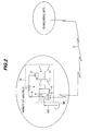
- Fig. 2 is a conceptual view showing the method of effectively utilizing natural gas with the gas-turbine power generating installation according to the first embodiment of the present invention.
- a first feature of the present invention resides in that a gas-turbine power generating installation 10 is installed in the vicinity of an overage gas field GF producing natural gas.
- natural gas is produced not only at reduced outturn, but also at low pressure.
- the gas-turbine power generating installation 10 is installed in the vicinity of the overage gas field. Because the gas-turbine power generating installation 10 requires a relatively low equipment cost and can convert the natural gas into fuel at high efficiency, it is suitable as an installation for effectively utilizing the natural gas.
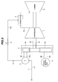
- the gas-turbine power generating installation 10 comprises a gas turbine compressor 1, a combustor 2, a turbine 3, a transmission 4, and a power generator 5.
- the gas-turbine power generating installation 10 is installed in the vicinity of the gas field GF producing natural gas NG, and the natural gas NG extracted from the gas field GF is introduced through a fuel gas supply line 7 as fuel for driving a turbine 3, thereby to generate electric power.
- the generated electric power is supplied to the consuming site via a cable C.
- the place where the generated electric power is consumed is not limited to an area outside the overage gas field, and the generated electric power may be consumed within the site of the overage gas field if there is a demand.
- the gas-turbine power generating installation 10 is ideally installed right above the outrage gas field GF, but it is often difficult to install the installation 10 right above the outrage gas field due to conditions of location, etc. In such a case, the natural gas must be supplied to the gas-turbine power generating installation 10 through a pipe. If the distance from the gas field GF increases, the overall length of the pipe also increases, which not only pushes up the pipe laying cost, but also increases a pressure loss in the pipe. For that reason, the term "the vicinity of the overage gas field GF" means the distance within which the natural gas extracted from the overage gas field can be supplied to the gas-turbine power generating installation 10 for operation of the gas turbine in a satisfactory way. In practice, the vicinity of the overage gas field GF means the distance within about 20 km, preferably about 10 km, from the gas field GF.
- a second feature of the present invention resides in that a (fuel gas) boosting compressor 6 is provided and driven by motive power obtained from a rotary shaft of the turbine 3 of the gas-turbine power generating installation 10.
- the pressure of the natural gas extracted from the outrage gas field is low.
- the pressure of fuel supplied to the combustor 2 of the gas turbine 3 must be higher than the pressure of burning air boosted up by the gas turbine compressor 1 and supplied to the combustor 2.
- this embodiment employs the boosting compressor 6 for realizing utilization of the low-pressure gas.
- the boosting compressor 6 is driven by the motive power obtained from the rotary shaft of the turbine 3 after a speed shift through the transmission 4. Accordingly, a new driving source, such as a motor, is not required.
- the natural gas at pressure boosted by the boosting compressor 6 is supplied to the combustor 2 through a check valve 8 and a fuel flow adjusting valve 9.
- Fig. 3 is a system diagram of the gas-turbine power generating installation according to the first embodiment of the present invention. Note that, in Fig. 3, the same symbols as those in Fig. 2 denote the same components.
- Fuel gas supplied to the gas turbine is burnt in the combustor 2 with burning air supplied from the gas turbine compressor 1, and the turbine 3 is driven by combustion gas from the combustor 1.
- the motive power obtained by the turbine 3 is used to drive the power generator 5 through the transmission 4, thereby generating electric power.
- the pressure of natural gas extracted from the outrage gas field is so low as not to be employed directly as fuel for the gas turbine, and therefore must be boosted.
- the boosting compressor 6 is driven by torque outputted from the transmission 4 of the power generator 5 to boost the fuel pressure to such an extent that the fuel can be supplied to the combustor 2 through the check valve 8 and the fuel flow adjusting valve 9.
- a pressure P1 of natural gas extracted from an outrage gas field is, e.g., lower than 10 ata.
- the extracted natural gas can no longer be supplied to a consuming site through a pipeline as having been practiced so far, and it is difficult to ensure a profit necessary from the viewpoints of maintaining pipeline equipment and obtaining satisfactory cost effectiveness.
- the method of liquefying and transporting the extracted natural gas also faces a difficulty in ensuring a profit necessary from the viewpoints of maintaining the liquefying and transporting equipment and obtaining satisfactory cost effectiveness.
- the gas turbine compressor 1 usually has a pressure ratio in the range of 10 to 20, a pressure P2 of the burning air is in the range of 10 to 20 ata. Therefore, if the pressures P1 and P2 remain at the respective levels, the natural gas cannot be supplied to the gas turbine combustor 2 because of improper pressure balance.
- the boosting compressor 6 is driven by torque transmitted from the shaft end of the compressor 1 through the transmission 4 for driving the power generator 5, whereby the natural gas extracted from the outrage gas field is supplied to the combustor 2 after the pressure thereof has been boosted to a pressure P3, e.g., 20 to 30 ata, that is required for the fuel supplied to the gas turbine combustor 2.
- the pressure P3 of the natural gas serving as fuel is set to a level of 20 to 30 ata higher than the burning air pressure P2 (10 to 20 ata).
- the boosting compressor 6 can be constructed as a part of the gas turbine and the overall installation can be made compact. Further, utilizing the shaft torque of the gas turbine for driving the boosting compressor 6 is able to achieve a smaller loss and higher efficiency as compared with the case of employing, instead of the shaft torque of the gas turbine, a separate motor (not shown) to drive the boosting compressor 6.
- the transmission 4 is not connected to the shaft end of the turbine 3 side, but it is connected to the shaft end of the compressor 1 side. The reason is that, because the temperature on the compressor 1 side is lower than that on the turbine 3 side, thermal elongation is smaller and clearances to be left in consideration of thermal deformations can be set to smaller values on the compressor 1 side.
- the power generator 5 and the boosting compressor 6 are connected to the transmission 4.
- a gas turbine suitable for the overage gas field is a medium-sized gas turbine with output power of 10000 to 100000 kw, taking into account the quantity of extracted gas.
- a rotation speed N1 of the medium-sized gas turbine is generally designed to be higher than a rotation speed N2 (3600 rpm (corresponding to 60 Hz) or 3000 rpm (corresponding to 50 Hz)) of the power generator.
- the rotation speed N1 of the compressor shaft end is about 7200 rpm. Therefore, the motive power of the compressor shaft is transmitted through a speed reducing gear 4a with a speed reducing ratio of 2 to 2.4 to the power generator 5 for supplying electric power to the consuming site.
- Te medium-sized gas turbine with output power of 10000 to 100000 kw can be designed as a compact installation and hence can be relatively easily installed in the vicinity of the drilling site. Further, by installing that type of gas turbine, for example, in the outrage gas field where outturn is reduced or the gas field where natural gas is produced in small quantity, it is possible to realize power generation appropriately adapted for the quantity of produced gas, and to provide a power generating system with good economy.
- the rotation speed N3 of the boosting compressor 6 for boosting the fuel pressure is desirably set to a relatively high level of 20000 to 30000 rpm, taking into account a smaller gas flow rate than that in the compressor 1 and a more compact size. For that reason, the boosting compressor 6 for boosting the lower pressure of the extracted gas to a level required as the fuel for the gas turbine combustor is supplied with the motive power through a speed increasing gear 4b with a speed increasing ratio of about 3 to 4.
- the transmission 4 comprises the speed reducing gear 4a for transmitting the motive power to the power generator 5 and the speed increasing gear 4b for transmitting the motive power to the boosting compressor 6.
- the boosting compressor 6 can be operated with high efficiency.
- associated equipment such as a motor, and an installation space for the associated equipment are required in the case of driving the boosting compressor 6 separately, those disadvantages are eliminated because the boosting compressor 6 is constructed as an integral part of the gas turbine. As a result, a compact structure can be realized in addition to the high efficiency described above.
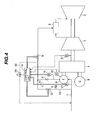
- Fig. 4 is a more detailed system diagram of the gas-turbine power generating installation according to the first embodiment of the present invention
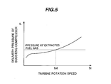
- Fig. 5 is a graph for explaining the delivery pressure of the boosting compressor used in the gas-turbine power generating installation according to the first embodiment of the present invention. Note that, in Fig. 4, the same symbols as those in Fig. 2 denote the same components.
- the construction shown in Fig. 4 includes, in addition to the components shown in Fig. 3, a control unit 14 for controlling the fuel flow adjusting valve 9, a startup fuel supply valve 12, and an anti-surge valve 24 in accordance with pressures detected by pressure gauges 17, 18 and the operation status of the gas turbine.
- the startup fuel supply valve 12 is disposed in a bypass line 15 that extends in parallel to a line where the boosting compressor 6 and the check valve 8 are connected in series. In the startup stage in which the rotation speed of the gas turbine is low, the startup fuel supply valve 12 is opened so that the natural gas serving as fuel is supplied to the combustor 2 via the bypass line 15.
- the delivery pressure of the boosting compressor 6 with reference to Fig. 5.
- the horizontal axis represents the rotation speed of the turbine 3, and the vertical axis represents the delivery pressure of the boosting compressor 6.
- the rotation speed of the boosting compressor 6 is also low and a pressure loss is caused in excess of the boosting effect developed by the boosting compressor 6 because the boosting compressor 6 itself acts as a resistance member. Therefore, the delivery pressure of the boosting compressor 6 may be often lower than the pressure of the extracted fuel gas. In such a case, there is a possibility that the fuel pressure is not sufficiently boosted and the required amount of fuel cannot be supplied to the combustor 2.
- the bypass line 15 is provided to supply the fuel gas to the combustor 2 while bypassing the boosting compressor 6.
- the control unit 14 opens the startup fuel supply valve 12 so that the fuel is supplied via the bypass line 15.
- the bypass line 15 for the startup is used during a period until the rotation speed of the turbine increases and the delivery pressure of the boosting compressor 6 rises up to the certain level.
- the control unit 14 closes the startup fuel supply valve 12 to stop the fuel supply via the bypass line 15 so that the fuel is supplied to the combustor 2 only through the boosting compressor 6.
- control unit 14 compares the delivery pressure of the boosting compressor 6 detected by the pressure gauge 18 after pressure boosting of the fuel gas with the pressure of the fuel gas extracted from the gas field, which is detected by the pressure gauge 17, and then closes the startup fuel supply valve 12, i.e., sets its opening degree to zero, when the delivery pressure of the boosting compressor 6 becomes higher than the pressure of the extracted fuel gas.
- Similar control can also be made by using a turbine tachometer 31 for detecting the rotation speed of the turbine 3 and a compressor tachometer 32 for detecting the rotation speed of the boosting compressor 6. More specifically, in the trial operation of the power generating installation, a characteristic of the delivery pressures of the boosting compressor 6 and the gas turbine compressor 1 versus the rotation speed of the turbine is measured to obtain a characteristic curve similar to that shown in Fig. 5. Then, the control unit 14 opens the startup fuel supply valve 12 when the turbine rotation speed measured by the tachometer 31 is lower than a rotation speed N4 shown in Fig.
- the turbine rotation speed is decided depending on the rotation speed of the boosting compressor 6 detected by the tachometer 32 and a gear ratio of the transmission 4, the opening/closing of the startup fuel supply valve 12 can also be controlled in accordance with the rotation speed of the boosting compressor 6 detected by the tachometer 32.
- the rotation speed of the power generator can be alternatively used to perform similar control.
- an anti-surge line 22 is provided for connection between the outlet side and the inlet side of the boosting compressor 6, and the anti-surge valve 24 is disposed midway the anti-surge line 22.
- the control unit 14 controls the anti-surge valve 24 in accordance with the operation status of the gas turbine to ensure a sufficient flow rate of the fuel by using the anti-surge line 22 so that stable operation can be realized over a full range from the startup to the rated-load operation of the gas turbine.
- the control unit 14 holds the fuel flow adjusting valve 9 closed. Then, as the rotation speed of the gas turbine increases, the delivery side of the boosting compressor 6 continues to be kept in a shutoff state. To avoid the operation in such a shutoff state, the control unit 14 opens the anti-surge valve 24 during the period from the startup of the gas turbine until it reaches the ignition rotation speed. As an alternative, the shutoff state can also be avoided by opening, instead of the anti-surge valve 24, the startup fuel supply valve 12 and forming a flow passage indicated by an arrow R1 in Fig. 4.
- the startup fuel supply valve 12 can be similarly employed as an anti-surge valve.
- Using the single valve 12 for dual purposes of supplying the startup fuel gas and serving as the anti-surge valve contributes to simplifying the line arrangement around the fuel gas boosting compressor and reducing the cost.
- control unit 14 opens the anti-surge valve 24 at the same time as cutoff of the fuel, thereby to prevent the fuel gas boosting compressor from being operated in the shutoff state. This enables the gas turbine to be stopped with safety.
- the gas-turbine power generating installation is also applicable to effectively utilize accompanying gas that is produced in oil fields concurrently during oil drilling.
- the fuel gas boosting compressor is driven by the motive power transmitted from the gas turbine shaft through the speed increasing gear
- the power generator is driven by the motive power transmitted from the gas turbine shaft through the speed reducing gear
- the speed increasing gear and the speed reducing gear are both constructed integrally with the transmission. Therefore, a compact gas turbine adaptable for the outrage gas field can be realized with high reliability and high efficiency.
- the existing plant is present in an outrage gas field or an oil field, and the gas-turbine power generating installation is installed there. Since the generating installation has a compact structure, the existing site can be effectively utilized.
- Fig. 6 is a detailed system diagram of the gas-turbine power generating installation according to the second embodiment of the present invention. Note that, in Fig. 6, the same symbols as those in Fig. 4 denote the same components.
- This embodiment is featured in that a startup (fuel gas) boosting compressor 21 and a motor 33 for driving the startup boosting compressor 21 are both disposed in the bypass line 15.
- the startup boosting compressor 21 employed only at the startup is disposed in the startup bypass line 15.
- the startup boosting compressor 21 is employed only for a short time at the startup, it is just required to have a small supply flow rate and a low delivery pressure.
- the power required for the motor 33 is also smaller than the rated power of the above-mentioned boosting compressor 6.
- the startup boosting compressor 21 has a small size and hence does not need a so large installation space.
- a control unit 14A drives the motor 33 to operate the startup boosting compressor 21 after the ignition rotation speed has been reached.
- the operation of the startup boosting compressor 21 may be started in anticipation of a time required for the startup boosting compressor 21 to operate in a desired state. This modification enables the startup boosting compressor 21 to provide a required delivery pressure just at the time when the gas turbine reaches the ignition rotation speed.
- the control unit 14A closes the startup fuel supply valve 12 to stop the fuel supply via the startup bypass line 15 and also stops the startup boosting compressor 21, while the fuel supply is started via the normal fuel gas supply line in which the fuel gas boosting compressor 6 is disposed.
- the gas turbine can be started up with high reliability without a failure such as misfire of the combustor.
- Fig. 7 is a detailed system diagram of the gas-turbine power generating installation according to the third embodiment of the present invention. Note that, in Fig. 7, the same symbols as those in Fig. 4 denote the same components.
- This embodiment includes a tank 36 and an on/off valve (fuel gas supply switching valve) 11 disposed in a line between the tank 36 and the boosting compressor 6.
- an on/off valve (fuel gas supply switching valve) 11 disposed in a line between the tank 36 and the boosting compressor 6.
- a control unit 14B opens the on/off valve 11 and connects the delivery line of the boosting compressor 6 to the tank 36 having a capacity that is relatively small, but is enough to store the fuel gas supplied from the boosting compressor 6, whereby the fuel gas is bled to the tank 36 for several minutes at the startup to protect the boosting compressor from the shutoff-state operation.
- the control unit 14B closes the on/off valve 11 connected to the tank 36 and simultaneously opens the fuel flow adjusting valve 9 connected to the combustor 2, whereupon the fuel gas is supplied to the combustor 2 for ignition.
- the shutoff-state operation can be avoided in addition to the advantages that, even when the pressure of the gas extracted from the outrage gas field is even lower, it is possible to start up the gas turbine by using the startup boosting compressor and to effectively utilize the gas that has been left unused in the past.
- Fig. 8 is a detailed system diagram of the gas-turbine power generating installation according to the fourth embodiment of the present invention. Note that, in Fig. 8, the same symbols as those in Fig. 4 denote the same components.
- This embodiment includes a switching valve 91 disposed in a line 7 for supplying fuel to the boosting compressor 6, and an air supply valve 13 and a check valve 23 both disposed in a line 34 connecting the delivery side of the gas turbine compressor 1 and the inlet side of the boosting compressor 6.
- a control unit 14C closes the switching valve 91 disposed in the line 7 for supplying fuel to the boosting compressor 6 and opens the air supply valve 13 disposed in the line 34 so that air delivered or extracted from the gas turbine compressor 1 is supplied to the boosting compressor 6. As a result, the air is caused to flow into the combustor 2 at a flow rate required for protecting the boosting compressor 6.
- the control unit 14C closes the air supply valve 13, opens the switching valve 91, and adjusts the opening degree of the fuel flow adjusting valve 9 after opening it. Then, the supplied fuel is ignited and the fuel gas is supplied to the combustor 2 at a required flow rate, thereby increasing the rotation speed and the load.
- the boosting compressor 6 can be avoided from being operated in the shutoff state, and reliability in the operation can be improved.
- the shutoff-state operation can be avoided in addition to the advantages that, even when the pressure of the gas extracted from the outrage gas field is even lower, it is possible to start up the gas turbine by using the startup boosting compressor and to effectively utilize the gas that has been left unused in the past.
- the embodiments of the present invention described above can provide the following advantages.
- an outrage gas field where outturn is reduced a difficulty occurs in obtaining a satisfactory profit from the economic point of view while maintaining the pipeline and the liquefying and transporting equipment which have been used so far.
- the installation cost of a new power generating installation can be offset and a profit can be obtained.
- the boosting compressor can be constructed as a part of the gas turbine and the overall installation can be made compact. Also, because the boosting compressor is directly driven by the shaft torque of the gas turbine, a smaller loss and higher efficiency can be achieved as compared with the case of driving the boosting compressor by a motor or the like. Further, it is possible to effectively utilize the natural gas that is produced in small quantity and at low pressure and therefore has not been utilized in the past, by installing the gas turbine provided with the shaft-driven boosting compressor as an integral part of the gas turbine in the vicinity of the overage gas field, generating electric power, and supplying the generated electric power to the consuming site.
- the fuel gas boosting compressor is driven in a directly coupled relation to the gas turbine shaft through the speed increasing gear
- the power generator is driven in a directly coupled relation to the gas turbine shaft through the speed reducing gear
- the speed increasing gear and the speed reducing gear are both constructed integrally with the transmission.
- the gas turbine is operated with the fuel flow adjusting valve fully closed.
- the operation of the gas turbine is performed while the delivery side of the boosting compressor for boosting the pressure of the fuel gas is in the shutoff state, thus resulting in a problem from the viewpoint of protection of the compressor components.
- the delivery line of the boosting compressor is connected to a small-sized tank and the fuel gas is bled to the tank for several minutes at the startup to protect the boosting compressor from the shutoff-state operation.
- the fuel gas supply switching valve is shifted to supply the fuel gas to the combustor for ignition.
- the boosting compressor can be avoided from being operated in the shutoff state, an excessive rise of the fuel temperature can be prevented, and reliability in the operation is improved.
- air delivered or extracted from the gas turbine compressor is supplied to the boosting compressor instead of using the above-mentioned tank.
- the air is caused to flow into the combustor at a flow rate required for protecting the boosting compressor.
- the air supply valve is closed, and the fuel flow adjusting valve is opened and adjusted in its opening degree.
- the supplied fuel is ignited and the fuel gas is supplied to the combustor at a required flow rate, thereby increasing the rotation speed and the load.
- the rotation speed of the boosting compressor is also low and a pressure loss is caused in excess of the boosting effect developed by the boosting compressor because the boosting compressor itself acts as a resistance member. Therefore, the delivery pressure of the boosting compressor may be often lower than the pressure of the extracted fuel gas. In such a case, there is a possibility that the fuel pressure is not sufficiently boosted and the required amount of fuel cannot be supplied to the combustor. In view of such a possibility, the bypass line is provided to supply the fuel gas to the combustor while bypassing the boosting compressor. During a period of the low-speed operation at the startup from the ignition rotation speed until the delivery pressure of the boosting compressor rises up to a certain level, the fuel is supplied via the bypass line, and highly reliable operation can be realized.
- the startup boosting compressor employed only at the startup is disposed in the startup bypass line. This arrangement enables the fuel to be sufficiently supplied at the startup even when the pressure of the extracted fuel gas is low.
- the flow rate of the fuel supplied to the combustor is relatively small. Therefore, the operation may come into a surge region depending on pressure and flow rate characteristics of the boosting compressor.
- the anti-surge line is provided to prevent the operation of the boosting compressor in the surge region.
- low-pressure fuel gas which is produced from an overage gas field and which has not been effectively used in the past can be employed to generate electric power with the gas turbine by employing an installation in which the power generator and the boosting compressor are constructed integrally with the transmission.
- the power generator and the boosting compressor are constructed integrally with the transmission.
Abstract
Description
- The present invention relates to a gas-turbine power generating installation and a method of operating the gas-turbine power generating installation. More particularly, the present invention relates to a gas-turbine power generating installation capable of employing gases produced in overage gas fields, etc., such as natural gas extracted from the overage gas fields at reduced outturn and low pressure, and accompanying gas produced at low pressure during oil extraction in oil fields, and also to a method of operating the gas-turbine power generating installation.
- In view of environment pollution in worldwide scale, regulations on exhaust gas from various engines have been urged in progress. Under such situations, natural gas is worthy of note as fuel giving less influence upon environments.
- Natural gas NG is transported from a gas field GF to a consuming site, as shown in Fig. 1, by a method of liquefying the natural gas with liquefying equipment in the gas field and transporting the liquefied gas to the consuming site by land or sea, or a method of transporting the natural gas, as it is, to the consuming site through a pipeline PL. The pipeline includes several booster stations BS for boosting the pressure of natural gas to compensate for a pressure loss caused as the natural gas flows through the pipeline. The interval between the booster stations BS is, e.g., several tens to several hundreds kilometers. General constructions of known gas-turbine power generating installations are disclosed in, e.g., JP-A-2003-166428 and JP-A-2002-327629.
- However, when natural gas fields become overage with the progress of gas extraction, outturn is reduced and a profit is no longer expected because of a relative increase of the cost for liquefying and transporting the natural gas or for transporting the natural gas through the pipeline. For that reason, it has been usual in the past that the natural gas extracted from those overage gas fields is not transported to a consuming site and hence not effectively utilized.
- Further, in oil fields, accompanying gas is produced concurrently during oil extraction, but such gas has also not been effectively utilized in the past.
- Accordingly, it is an object of the present invention to provide a gas-turbine power generating installation capable of employing gases produced in overage gas fields, etc., such as natural gas extracted from the overage gas fields and accompanying gas produced in oil fields, and to a method of operating the gas-turbine power generating installation.
- (1) To achieve the above object, the present invention provides a gas-turbine power generating installation including a gas turbine installed in the vicinity of an outrage gas field or an oil field and generating electric power with the gas turbine by using natural gas produced in the outrage gas field or accompanying gas produced in the oil field, the generated electric power being supplied to a consuming site, wherein the gas turbine is a gas turbine in which air compressed by a compressor is introduced to a combustor for combustion after being mixed with fuel, a turbine is driven by generated combustion gas, and a power generator is driven by motive power obtained from a rotary shaft of the gas turbine, the installation further includes a boosting compressor driven by the motive power obtained from the rotary shaft of the gas turbine, and the natural gas or the accompanying gas is boosted in pressure by the boosting compressor and supplied as fuel to the combustor. With that arrangement, gases produced in outrage gas fields, etc. can be effectively utilized.
- (2) In above (1), preferably, the power generator is driven by the rotary shaft of the gas turbine through a speed reducing gear, and the boosting compressor is driven by the rotary shaft of the gas turbine through a speed increasing gear.
- (3) In above (2), preferably, the speed reducing gear and the speed increasing gear receive the motive power from the shaft of the gas turbine on the compressor side.
- (4) In above (1), preferably, the gas-turbine power generating installation further includes a fuel flow adjusting valve disposed in a line extending from an outlet of the boosting compressor to the combustor in the gas turbine; a tank; a line connecting an intermediate point between the outlet of the boosting compressor and the fuel flow adjusting valve to the tank; and an on/off valve disposed in the line connected to the tank.
- (5) In above (1), preferably, the gas-turbine power generating installation further includes an air line extending from an outlet or an intermediate position of the compressor in the gas turbine to an inlet of the boosting compressor; an air supply valve disposed in the air line; and a switching valve disposed on the inlet side of the boosting compressor upstream of a joint position of the air line.
- (6) In above (1), preferably, the gas-turbine power generating installation further includes a bypass line connecting an inlet and an outlet of the boosting compressor in the gas turbine; a startup fuel gas supply valve disposed in the bypass line; and pressure gauges for measuring an inlet pressure and an outlet pressure of the boosting compressor.
- (7) In above (1), preferably, the gas-turbine power generating installation further includes a bypass line connecting an inlet and an outlet of the boosting compressor in the gas turbine; a startup fuel gas supply valve disposed in the bypass line; and a tachometer for detecting a rotation speed of a shaft of the boosting compressor, the turbine or the power generator.
- (8) In above (1), preferably, the gas-turbine power generating installation further includes a bypass line connecting an inlet and an outlet of the boosting compressor in the gas turbine; and a startup fuel gas boosting compressor and a startup fuel gas supply valve both disposed in the bypass line.
- (9) In above (1), preferably, the gas-turbine power generating installation further includes an anti-surge line extending to an inlet of the boosting compressor from an intermediate point of a line extending from an outlet of the boosting compressor to the combustor in the gas turbine; and an anti-surge valve disposed in the anti-surge line.
- (10) To achieve the above object, the present invention also provides a gas-turbine power generating installation comprising a gas turbine installed in the vicinity of an outrage gas field or an oil field and including a first compressor for compressing air, a combustor for generating combustion gas from fuel and the air compressed by the first compressor, and a turbine driven by the combustion gas; a power generator driven by motive power from a rotary shaft of the gas turbine; a second compressor driven by motive power from the rotary shaft of the gas turbine; and a fuel supply line for compressing natural gas produced in the outrage gas field or accompanying gas produced in the oil field by the second compressor and supplying the compressed gas, as fuel, to the combustor. With that arrangement, gases produced in outrage gas fields, etc. can be effectively utilized.
- (11) To achieve the above object, the present invention further provides a method of operating a gas-turbine power generating installation, the method comprising the steps of installing a gas turbine in the vicinity of an outrage gas field or an oil field, the gas turbine including a first compressor for compressing air, a combustor for generating combustion gas from fuel and the air compressed by the first compressor, and a turbine driven by the combustion gas; driving a power generator by motive power from a rotary shaft of the gas turbine; driving a second compressor by motive power from the rotary shaft of the gas turbine; and compressing natural gas produced in the outrage gas field or accompanying gas produced in the oil field by the second compressor and supplying the compressed gas, as fuel, to the combustor. With that method, gases produced in outrage gas fields, etc. can be effectively utilized.
- (12) To achieve the above object, the present invention still further provides a method of operating a gas-turbine power generating installation installed in the vicinity of an outrage gas field or an oil field, the method comprising the steps of supplying, as fuel, natural gas produced in the outrage gas field or accompanying gas produced in the oil field to a combustor of the gas-turbine power generating installation; and generating electric power within a distance of 20 km from the outrage gas field or the oil field with a power generator having a capacity of 10000 to 100000 kw and driven by motive power from a rotary shaft of the gas turbine. With that method, gases produced in outrage gas fields, etc. can be effectively utilized.
- (13) To achieve the above object, the present invention still further provides a method of operating a gas-turbine power generating installation installed in the vicinity of an outrage gas field or an oil field, the method comprising the steps of compressing natural gas produced in the outrage gas field or accompanying gas produced in the oil field to a desired pressure by a gas compressing unit which is driven by motive power from a rotary shaft of a gas turbine in the gas-turbine power generating installation, and supplying the compressed gas, as fuel, to a combustor of the gas-turbine power generating installation; and generating electric power with a power generator driven by motive power from a rotary shaft of the gas turbine.
-
- With that method, gases produced in outrage gas fields, etc. can be effectively utilized.
- According to the present invention, it is possible to effectively utilize gases produced in outrage gas fields, etc.
-
- Fig. 1 is an illustration for explaining conventional methods of utilizing natural gas;
- Fig. 2 is a conceptual view showing a method of effectively utilizing natural gas with a gas-turbine power generating installation according to a first embodiment of the present invention;
- Fig. 3 is a system diagram of the gas-turbine power generating installation according to the first embodiment of the present invention;
- Fig. 4 is a more detailed system diagram of the gas-turbine power generating installation according to the first embodiment of the present invention;
- Fig. 5 is a graph for explaining the delivery pressure of a boosting compressor used in the gas-turbine power generating installation according to the first embodiment of the present invention;
- Fig. 6 is a detailed system diagram of a gas-turbine power generating installation according to a second embodiment of the present invention;
- Fig. 7 is a detailed system diagram of a gas-turbine power generating installation according to a third embodiment of the present invention; and
- Fig. 8 is a detailed system diagram of a gas-turbine power generating installation according to a fourth embodiment of the present invention.
-
- A gas-turbine power generating installation employing gases produced in overage gas fields, etc. and a method of operating the installation, according to a first embodiment of the present invention, will be described below with reference to Figs. 2 to 5. Note that the following description is made, by way of example, in connection with natural gas produced in overage gas fields.
- First, the basic concept of a method of effectively utilizing natural gas with the gas-turbine power generating installation according to this embodiment will be described with reference to Fig. 2.
- Fig. 2 is a conceptual view showing the method of effectively utilizing natural gas with the gas-turbine power generating installation according to the first embodiment of the present invention.
- A first feature of the present invention resides in that a gas-turbine
power generating installation 10 is installed in the vicinity of an overage gas field GF producing natural gas. Generally, in overage gas fields, natural gas is produced not only at reduced outturn, but also at low pressure. To effectively utilize such natural gas produced in small quantity and at low pressure, the gas-turbinepower generating installation 10 is installed in the vicinity of the overage gas field. Because the gas-turbinepower generating installation 10 requires a relatively low equipment cost and can convert the natural gas into fuel at high efficiency, it is suitable as an installation for effectively utilizing the natural gas. - The gas-turbine
power generating installation 10 comprises agas turbine compressor 1, acombustor 2, aturbine 3, atransmission 4, and apower generator 5. In the present invention, the gas-turbinepower generating installation 10 is installed in the vicinity of the gas field GF producing natural gas NG, and the natural gas NG extracted from the gas field GF is introduced through a fuelgas supply line 7 as fuel for driving aturbine 3, thereby to generate electric power. The generated electric power is supplied to the consuming site via a cable C. The place where the generated electric power is consumed is not limited to an area outside the overage gas field, and the generated electric power may be consumed within the site of the overage gas field if there is a demand. - The gas-turbine
power generating installation 10 is ideally installed right above the outrage gas field GF, but it is often difficult to install theinstallation 10 right above the outrage gas field due to conditions of location, etc. In such a case, the natural gas must be supplied to the gas-turbinepower generating installation 10 through a pipe. If the distance from the gas field GF increases, the overall length of the pipe also increases, which not only pushes up the pipe laying cost, but also increases a pressure loss in the pipe. For that reason, the term "the vicinity of the overage gas field GF" means the distance within which the natural gas extracted from the overage gas field can be supplied to the gas-turbinepower generating installation 10 for operation of the gas turbine in a satisfactory way. In practice, the vicinity of the overage gas field GF means the distance within about 20 km, preferably about 10 km, from the gas field GF. - A second feature of the present invention resides in that a (fuel gas)
boosting compressor 6 is provided and driven by motive power obtained from a rotary shaft of theturbine 3 of the gas-turbinepower generating installation 10. The pressure of the natural gas extracted from the outrage gas field is low. On the other hand, the pressure of fuel supplied to thecombustor 2 of thegas turbine 3 must be higher than the pressure of burning air boosted up by thegas turbine compressor 1 and supplied to thecombustor 2. In view of that condition, this embodiment employs the boostingcompressor 6 for realizing utilization of the low-pressure gas. Then, the boostingcompressor 6 is driven by the motive power obtained from the rotary shaft of theturbine 3 after a speed shift through thetransmission 4. Accordingly, a new driving source, such as a motor, is not required. The natural gas at pressure boosted by the boostingcompressor 6 is supplied to thecombustor 2 through acheck valve 8 and a fuelflow adjusting valve 9. - The construction of the gas-turbine power generating installation according to this embodiment will be described below with reference to Fig. 3.
- Fig. 3 is a system diagram of the gas-turbine power generating installation according to the first embodiment of the present invention. Note that, in Fig. 3, the same symbols as those in Fig. 2 denote the same components.
- Fuel gas supplied to the gas turbine is burnt in the
combustor 2 with burning air supplied from thegas turbine compressor 1, and theturbine 3 is driven by combustion gas from thecombustor 1. The motive power obtained by theturbine 3 is used to drive thepower generator 5 through thetransmission 4, thereby generating electric power. The pressure of natural gas extracted from the outrage gas field is so low as not to be employed directly as fuel for the gas turbine, and therefore must be boosted. To this end, the boostingcompressor 6 is driven by torque outputted from thetransmission 4 of thepower generator 5 to boost the fuel pressure to such an extent that the fuel can be supplied to thecombustor 2 through thecheck valve 8 and the fuelflow adjusting valve 9. - Here, a description is made of pressures in a general gas turbine. Usually, a pressure P1 of natural gas extracted from an outrage gas field is, e.g., lower than 10 ata. When outturn reduces and the pressure of the natural gas lowers, the extracted natural gas can no longer be supplied to a consuming site through a pipeline as having been practiced so far, and it is difficult to ensure a profit necessary from the viewpoints of maintaining pipeline equipment and obtaining satisfactory cost effectiveness. In addition, the method of liquefying and transporting the extracted natural gas also faces a difficulty in ensuring a profit necessary from the viewpoints of maintaining the liquefying and transporting equipment and obtaining satisfactory cost effectiveness.
- On the other hand, because the
gas turbine compressor 1 usually has a pressure ratio in the range of 10 to 20, a pressure P2 of the burning air is in the range of 10 to 20 ata.
Therefore, if the pressures P1 and P2 remain at the respective levels, the natural gas cannot be supplied to thegas turbine combustor 2 because of improper pressure balance. To obtain proper pressure balance, the boostingcompressor 6 is driven by torque transmitted from the shaft end of thecompressor 1 through thetransmission 4 for driving thepower generator 5, whereby the natural gas extracted from the outrage gas field is supplied to thecombustor 2 after the pressure thereof has been boosted to a pressure P3, e.g., 20 to 30 ata, that is required for the fuel supplied to thegas turbine combustor 2. Taking into account a pressure loss in thecombustor 2, the pressure P3 of the natural gas serving as fuel is set to a level of 20 to 30 ata higher than the burning air pressure P2 (10 to 20 ata). With the arrangement of transmitting the driving force from the gas turbine shaft to the boostingcompressor 6 through thetransmission 4, the boostingcompressor 6 can be constructed as a part of the gas turbine and the overall installation can be made compact. Further, utilizing the shaft torque of the gas turbine for driving the boostingcompressor 6 is able to achieve a smaller loss and higher efficiency as compared with the case of employing, instead of the shaft torque of the gas turbine, a separate motor (not shown) to drive the boostingcompressor 6. Thus, it is possible to effectively utilize the natural gas that is produced in small quantity and at low pressure and hence has not been utilized in the past, by installing the gas turbine provided with the shaft-driven boostingcompressor 6 as its integral part in the vicinity of the overage gas field, generating electric power, and supplying the generated electric power to the consuming site. - Next, the shaft arrangement for driving the boosting
compressor 6 will be described below. Thetransmission 4 is not connected to the shaft end of theturbine 3 side, but it is connected to the shaft end of thecompressor 1 side. The reason is that, because the temperature on thecompressor 1 side is lower than that on theturbine 3 side, thermal elongation is smaller and clearances to be left in consideration of thermal deformations can be set to smaller values on thecompressor 1 side. Thepower generator 5 and the boostingcompressor 6 are connected to thetransmission 4. - A gas turbine suitable for the overage gas field is a medium-sized gas turbine with output power of 10000 to 100000 kw, taking into account the quantity of extracted gas. A rotation speed N1 of the medium-sized gas turbine is generally designed to be higher than a rotation speed N2 (3600 rpm (corresponding to 60 Hz) or 3000 rpm (corresponding to 50 Hz)) of the power generator. In the case of a gas turbine with output power of 20000 to 30000 kw, for example, the rotation speed N1 of the compressor shaft end is about 7200 rpm. Therefore, the motive power of the compressor shaft is transmitted through a
speed reducing gear 4a with a speed reducing ratio of 2 to 2.4 to thepower generator 5 for supplying electric power to the consuming site. Te medium-sized gas turbine with output power of 10000 to 100000 kw can be designed as a compact installation and hence can be relatively easily installed in the vicinity of the drilling site. Further, by installing that type of gas turbine, for example, in the outrage gas field where outturn is reduced or the gas field where natural gas is produced in small quantity, it is possible to realize power generation appropriately adapted for the quantity of produced gas, and to provide a power generating system with good economy. - The rotation speed N3 of the boosting
compressor 6 for boosting the fuel pressure is desirably set to a relatively high level of 20000 to 30000 rpm, taking into account a smaller gas flow rate than that in thecompressor 1 and a more compact size. For that reason, the boostingcompressor 6 for boosting the lower pressure of the extracted gas to a level required as the fuel for the gas turbine combustor is supplied with the motive power through aspeed increasing gear 4b with a speed increasing ratio of about 3 to 4. - As described above, the
transmission 4 comprises thespeed reducing gear 4a for transmitting the motive power to thepower generator 5 and thespeed increasing gear 4b for transmitting the motive power to the boostingcompressor 6. With such an arrangement, since not only the rotation speed of thepower generator 5, but also the rotation speed of the boostingcompressor 6 are mechanically decided with control of the rotation speed of the gas turbine, the boostingcompressor 6 can be operated with high efficiency. Further, while associated equipment, such as a motor, and an installation space for the associated equipment are required in the case of driving the boostingcompressor 6 separately, those disadvantages are eliminated because the boostingcompressor 6 is constructed as an integral part of the gas turbine. As a result, a compact structure can be realized in addition to the high efficiency described above. - The construction of the gas-turbine power generating installation according to this embodiment will be described in more detail below with reference to Figs. 4 and 5.
- Fig. 4 is a more detailed system diagram of the gas-turbine power generating installation according to the first embodiment of the present invention, and Fig. 5 is a graph for explaining the delivery pressure of the boosting compressor used in the gas-turbine power generating installation according to the first embodiment of the present invention. Note that, in Fig. 4, the same symbols as those in Fig. 2 denote the same components.
- The construction shown in Fig. 4 includes, in addition to the components shown in Fig. 3, a
control unit 14 for controlling the fuelflow adjusting valve 9, a startupfuel supply valve 12, and ananti-surge valve 24 in accordance with pressures detected bypressure gauges - The startup
fuel supply valve 12 is disposed in abypass line 15 that extends in parallel to a line where the boostingcompressor 6 and thecheck valve 8 are connected in series. In the startup stage in which the rotation speed of the gas turbine is low, the startupfuel supply valve 12 is opened so that the natural gas serving as fuel is supplied to thecombustor 2 via thebypass line 15. - A description is now made of the delivery pressure of the boosting
compressor 6 with reference to Fig. 5. In the graph of Fig. 5, the horizontal axis represents the rotation speed of theturbine 3, and the vertical axis represents the delivery pressure of the boostingcompressor 6. As seen from Fig. 5, in the startup stage in which the rotation speed of the gas turbine is low, the rotation speed of the boostingcompressor 6 is also low and a pressure loss is caused in excess of the boosting effect developed by the boostingcompressor 6 because the boostingcompressor 6 itself acts as a resistance member. Therefore, the delivery pressure of the boostingcompressor 6 may be often lower than the pressure of the extracted fuel gas. In such a case, there is a possibility that the fuel pressure is not sufficiently boosted and the required amount of fuel cannot be supplied to thecombustor 2. In view of such a possibility, as shown in Fig. 4, thebypass line 15 is provided to supply the fuel gas to thecombustor 2 while bypassing the boostingcompressor 6. During a period of the low-pressure operation at the startup from the ignition rotation speed until the delivery pressure of the boostingcompressor 6 rises up to a certain level, thecontrol unit 14 opens the startupfuel supply valve 12 so that the fuel is supplied via thebypass line 15. Thus, thebypass line 15 for the startup is used during a period until the rotation speed of the turbine increases and the delivery pressure of the boostingcompressor 6 rises up to the certain level. After the delivery pressure of the boostingcompressor 6 has risen up to the certain level, thecontrol unit 14 closes the startupfuel supply valve 12 to stop the fuel supply via thebypass line 15 so that the fuel is supplied to thecombustor 2 only through the boostingcompressor 6. - In practice, the
control unit 14 compares the delivery pressure of the boostingcompressor 6 detected by thepressure gauge 18 after pressure boosting of the fuel gas with the pressure of the fuel gas extracted from the gas field, which is detected by thepressure gauge 17, and then closes the startupfuel supply valve 12, i.e., sets its opening degree to zero, when the delivery pressure of the boostingcompressor 6 becomes higher than the pressure of the extracted fuel gas. - Instead of the above-described method using the pressure gauges 17 and 18, similar control can also be made by using a
turbine tachometer 31 for detecting the rotation speed of theturbine 3 and acompressor tachometer 32 for detecting the rotation speed of the boostingcompressor 6. More specifically, in the trial operation of the power generating installation, a characteristic of the delivery pressures of the boostingcompressor 6 and thegas turbine compressor 1 versus the rotation speed of the turbine is measured to obtain a characteristic curve similar to that shown in Fig. 5. Then, thecontrol unit 14 opens the startupfuel supply valve 12 when the turbine rotation speed measured by thetachometer 31 is lower than a rotation speed N4 shown in Fig. 5, i.e., when the delivery pressure of the boostingcompressor 6 is lower than the pressure of the extracted fuel gas, and it closes the startupfuel supply valve 12 when the turbine rotation speed exceeds above the rotation speed N4. Because the turbine rotation speed is decided depending on the rotation speed of the boostingcompressor 6 detected by thetachometer 32 and a gear ratio of thetransmission 4, the opening/closing of the startupfuel supply valve 12 can also be controlled in accordance with the rotation speed of the boostingcompressor 6 detected by thetachometer 32. The rotation speed of the power generator can be alternatively used to perform similar control. - A description is now made of the
anti-surge valve 24. During the speed increasing stage or the low-load operation of the gas turbine, the flow rate of the fuel supplied to thecombustor 2 is smaller than that during the rated operation. Therefore, the operation may come into a surge region depending on pressure and flow rate characteristics of the boostingcompressor 6. To prevent the operation of the boostingcompressor 6 in the surge region, ananti-surge line 22 is provided for connection between the outlet side and the inlet side of the boostingcompressor 6, and theanti-surge valve 24 is disposed midway theanti-surge line 22. Thecontrol unit 14 controls theanti-surge valve 24 in accordance with the operation status of the gas turbine to ensure a sufficient flow rate of the fuel by using theanti-surge line 22 so that stable operation can be realized over a full range from the startup to the rated-load operation of the gas turbine. - Further, during a period from the startup of the gas turbine until it reaches the ignition rotation speed, the rotation speed of the gas turbine is increased by a driving motor, and the
control unit 14 holds the fuelflow adjusting valve 9 closed. Then, as the rotation speed of the gas turbine increases, the delivery side of the boostingcompressor 6 continues to be kept in a shutoff state. To avoid the operation in such a shutoff state, thecontrol unit 14 opens theanti-surge valve 24 during the period from the startup of the gas turbine until it reaches the ignition rotation speed. As an alternative, the shutoff state can also be avoided by opening, instead of theanti-surge valve 24, the startupfuel supply valve 12 and forming a flow passage indicated by an arrow R1 in Fig. 4. In other words, after the delivery pressure of the fuel gas boosting compressor has risen to the certain level through the startup, ignition and speed increasing stages and the fuel supply via the bypass line is stopped, the startupfuel supply valve 12 can be similarly employed as an anti-surge valve. Using thesingle valve 12 for dual purposes of supplying the startup fuel gas and serving as the anti-surge valve contributes to simplifying the line arrangement around the fuel gas boosting compressor and reducing the cost. - In addition, when the turbine is stopped, the
control unit 14 opens theanti-surge valve 24 at the same time as cutoff of the fuel, thereby to prevent the fuel gas boosting compressor from being operated in the shutoff state. This enables the gas turbine to be stopped with safety. - While the above description has been made in connection with, by way of example, the outrage gas field, the gas-turbine power generating installation is also applicable to effectively utilize accompanying gas that is produced in oil fields concurrently during oil drilling.
- According to this first embodiment, as described above, even in an especial situation such as an outrage gas field, natural gas produced in the outrage gas field and having been left unused in the past can be effectively utilized by generating electric power with the gas-turbine power generating installation installed in the vicinity of the overage gas field and supplying the generated electric power to the consuming site without employing the pipeline and the liquefying and transporting equipment which have been used so far. By selling the generated electric power, the installation cost of a new power generating installation can be offset and a profit can be obtained.
Further, the cost required to repair, manage and maintain the pipeline and the liquefying and transporting equipment can also be cut down. - Moreover, the fuel gas boosting compressor is driven by the motive power transmitted from the gas turbine shaft through the speed increasing gear, the power generator is driven by the motive power transmitted from the gas turbine shaft through the speed reducing gear, and the speed increasing gear and the speed reducing gear are both constructed integrally with the transmission. Therefore, a compact gas turbine adaptable for the outrage gas field can be realized with high reliability and high efficiency. Usually, the existing plant is present in an outrage gas field or an oil field, and the gas-turbine power generating installation is installed there. Since the generating installation has a compact structure, the existing site can be effectively utilized.
- The detailed construction of a gas-turbine power generating installation according to a second embodiment of the present invention will be described below with reference to Fig. 6.
- Fig. 6 is a detailed system diagram of the gas-turbine power generating installation according to the second embodiment of the present invention. Note that, in Fig. 6, the same symbols as those in Fig. 4 denote the same components.
- This embodiment is featured in that a startup (fuel gas) boosting
compressor 21 and amotor 33 for driving thestartup boosting compressor 21 are both disposed in thebypass line 15. In view of the case in which the pressure of fuel gas extracted from a gas field is so low that the fuel gas cannot be supplied to thecombustor 2 by utilizing thebypass line 15 provided to supply the fuel gas for the startup as described above, thestartup boosting compressor 21 employed only at the startup is disposed in thestartup bypass line 15. Because thestartup boosting compressor 21 is employed only for a short time at the startup, it is just required to have a small supply flow rate and a low delivery pressure. Correspondingly, the power required for themotor 33 is also smaller than the rated power of the above-mentioned boostingcompressor 6. Further, thestartup boosting compressor 21 has a small size and hence does not need a so large installation space. - Because the fuel is supplied only after the ignition rotation speed has been reached, a
control unit 14A drives themotor 33 to operate thestartup boosting compressor 21 after the ignition rotation speed has been reached. As an alternative, to shorten the startup time of the gas turbine, the operation of thestartup boosting compressor 21 may be started in anticipation of a time required for thestartup boosting compressor 21 to operate in a desired state. This modification enables thestartup boosting compressor 21 to provide a required delivery pressure just at the time when the gas turbine reaches the ignition rotation speed. After the ignition of thecombustor 2 and the speed increasing stage of the gas turbine, when the delivery pressure of the fuelgas boosting compressor 6 rises to a level sufficient for allowing the fuel to be supplied to the combustor as described above, thecontrol unit 14A closes the startupfuel supply valve 12 to stop the fuel supply via thestartup bypass line 15 and also stops thestartup boosting compressor 21, while the fuel supply is started via the normal fuel gas supply line in which the fuelgas boosting compressor 6 is disposed. As a result, since the fuel can be supplied at a sufficient pressure level to the gas turbine at the startup thereof, the gas turbine can be started up with high reliability without a failure such as misfire of the combustor. - According to this second embodiment, as described above, even when the pressure of the gas extracted from the outrage gas field is even lower, it is possible to start up the gas turbine by using the startup boosting compressor and to effectively utilize the gas that has been left unused in the past.
- The detailed construction of a gas-turbine power generating installation according to a third embodiment of the present invention will be described below with reference to Fig. 7.
- Fig. 7 is a detailed system diagram of the gas-turbine power generating installation according to the third embodiment of the present invention. Note that, in Fig. 7, the same symbols as those in Fig. 4 denote the same components.
- This embodiment includes a
tank 36 and an on/off valve (fuel gas supply switching valve) 11 disposed in a line between thetank 36 and the boostingcompressor 6. During the period from the startup of the gas turbine until it reaches the ignition rotation speed, the rotation speed of the gas turbine is increased by the driving motor, and hence the fuel supply to the gas turbine is not needed. During that period, therefore, the gas turbine is operated with the fuelflow adjusting valve 9 closed. In other words, the operation of the gas turbine is performed while the delivery side of the boostingcompressor 6 for boosting the pressure of the fuel gas is in the shutoff state, thus resulting in such a problem from the viewpoint of component protection that the compressor temperature may rise excessively. This problem is attributable to that, because the boostingcompressor 6 is coupled to the rotary shaft of the gas turbine, the boosting compressor which should be kept stopped is also rotated. Accordingly, during the period from the startup until the ignition rotation speed is reached, acontrol unit 14B opens the on/offvalve 11 and connects the delivery line of the boostingcompressor 6 to thetank 36 having a capacity that is relatively small, but is enough to store the fuel gas supplied from the boostingcompressor 6, whereby the fuel gas is bled to thetank 36 for several minutes at the startup to protect the boosting compressor from the shutoff-state operation. When the gas turbine increases its speed and reaches the ignition rotation speed, thecontrol unit 14B closes the on/offvalve 11 connected to thetank 36 and simultaneously opens the fuelflow adjusting valve 9 connected to thecombustor 2, whereupon the fuel gas is supplied to thecombustor 2 for ignition. With the above-described control process, the boostingcompressor 6 can be avoided from being operated in the shutoff state, and reliability in the operation can be improved. - According to this third embodiment, as described above, the shutoff-state operation can be avoided in addition to the advantages that, even when the pressure of the gas extracted from the outrage gas field is even lower, it is possible to start up the gas turbine by using the startup boosting compressor and to effectively utilize the gas that has been left unused in the past.
- The detailed construction of a gas-turbine power generating installation according to a fourth embodiment of the present invention will be described below with reference to Fig. 8.
- Fig. 8 is a detailed system diagram of the gas-turbine power generating installation according to the fourth embodiment of the present invention. Note that, in Fig. 8, the same symbols as those in Fig. 4 denote the same components.
- This embodiment includes a switching
valve 91 disposed in aline 7 for supplying fuel to the boostingcompressor 6, and anair supply valve 13 and acheck valve 23 both disposed in aline 34 connecting the delivery side of thegas turbine compressor 1 and the inlet side of the boostingcompressor 6. To prevent the shutoff-state operation of the boostingcompressor 6 described above with reference to Fig. 7, acontrol unit 14C closes the switchingvalve 91 disposed in theline 7 for supplying fuel to the boostingcompressor 6 and opens theair supply valve 13 disposed in theline 34 so that air delivered or extracted from thegas turbine compressor 1 is supplied to the boostingcompressor 6. As a result, the air is caused to flow into thecombustor 2 at a flow rate required for protecting the boostingcompressor 6. After the gas turbine has reached the ignition rotation speed, thecontrol unit 14C closes theair supply valve 13, opens the switchingvalve 91, and adjusts the opening degree of the fuelflow adjusting valve 9 after opening it. Then, the supplied fuel is ignited and the fuel gas is supplied to thecombustor 2 at a required flow rate, thereby increasing the rotation speed and the load. With the above-described control process, the boostingcompressor 6 can be avoided from being operated in the shutoff state, and reliability in the operation can be improved. - According to this fourth embodiment, as described above, the shutoff-state operation can be avoided in addition to the advantages that, even when the pressure of the gas extracted from the outrage gas field is even lower, it is possible to start up the gas turbine by using the startup boosting compressor and to effectively utilize the gas that has been left unused in the past.
- Without describing every possible configuration explicitly, it goes without saying that the components of the
embodiments 1 to 4 described above may be combined in any configuration suitable to put the invention into practice, according to the knowledge of an expert skilled in the art and the special demands of the respective desired application. - The embodiments of the present invention described above can provide the following advantages. In an outrage gas field where outturn is reduced, a difficulty occurs in obtaining a satisfactory profit from the economic point of view while maintaining the pipeline and the liquefying and transporting equipment which have been used so far. It is therefore economically advantageous to generate electric power using natural gas, which is produced in the outrage gas field, at the site of drilling and to transport the generated electric power to the consuming site without employing the pipeline and the liquefying and transporting equipment which have been used so far. By selling the generated electric power, the installation cost of a new power generating installation can be offset and a profit can be obtained.
- Another advantage is that, because of the arrangement of transmitting the driving force from the gas turbine shaft to the fuel gas boosting compressor through the speed increasing gear, the boosting compressor can be constructed as a part of the gas turbine and the overall installation can be made compact. Also, because the boosting compressor is directly driven by the shaft torque of the gas turbine, a smaller loss and higher efficiency can be achieved as compared with the case of driving the boosting compressor by a motor or the like. Further, it is possible to effectively utilize the natural gas that is produced in small quantity and at low pressure and therefore has not been utilized in the past, by installing the gas turbine provided with the shaft-driven boosting compressor as an integral part of the gas turbine in the vicinity of the overage gas field, generating electric power, and supplying the generated electric power to the consuming site.
- The fuel gas boosting compressor is driven in a directly coupled relation to the gas turbine shaft through the speed increasing gear, the power generator is driven in a directly coupled relation to the gas turbine shaft through the speed reducing gear, and the speed increasing gear and the speed reducing gear are both constructed integrally with the transmission. Accordingly, a compact gas turbine adaptable for the outrage gas field can be realized with high reliability and high efficiency. In a usual situation that the existing plant is present in an outrage gas field or an oil field and the gas-turbine power generating installation is installed there, the generating installation having a compact structure enables the existing site to be effectively utilized.
- During the period from the startup of the gas turbine until it reaches the ignition rotation speed, the rotation speed of the gas turbine is increased by the driving motor, and hence the fuel supply to the gas turbine is not needed. During that period, therefore, the gas turbine is operated with the fuel flow adjusting valve fully closed. In other words, the operation of the gas turbine is performed while the delivery side of the boosting compressor for boosting the pressure of the fuel gas is in the shutoff state, thus resulting in a problem from the viewpoint of protection of the compressor components. To avoid that problem, the delivery line of the boosting compressor is connected to a small-sized tank and the fuel gas is bled to the tank for several minutes at the startup to protect the boosting compressor from the shutoff-state operation. When the gas turbine increases its speed and reaches the ignition rotation speed, the fuel gas supply switching valve is shifted to supply the fuel gas to the combustor for ignition. With that control process, the boosting compressor can be avoided from being operated in the shutoff state, an excessive rise of the fuel temperature can be prevented, and reliability in the operation is improved.
- Alternatively, to prevent the shutoff-state operation of the boosting compressor, air delivered or extracted from the gas turbine compressor is supplied to the boosting compressor instead of using the above-mentioned tank. The air is caused to flow into the combustor at a flow rate required for protecting the boosting compressor. After the gas turbine has reached the ignition rotation speed, the air supply valve is closed, and the fuel flow adjusting valve is opened and adjusted in its opening degree. The supplied fuel is ignited and the fuel gas is supplied to the combustor at a required flow rate, thereby increasing the rotation speed and the load. With that control process, the boosting compressor can be avoided from being operated in the shutoff state, and reliability in the operation can be improved.
- Further, in the startup stage in which the rotation speed of the gas turbine is low, the rotation speed of the boosting compressor is also low and a pressure loss is caused in excess of the boosting effect developed by the boosting compressor because the boosting compressor itself acts as a resistance member. Therefore, the delivery pressure of the boosting compressor may be often lower than the pressure of the extracted fuel gas. In such a case, there is a possibility that the fuel pressure is not sufficiently boosted and the required amount of fuel cannot be supplied to the combustor. In view of such a possibility, the bypass line is provided to supply the fuel gas to the combustor while bypassing the boosting compressor. During a period of the low-speed operation at the startup from the ignition rotation speed until the delivery pressure of the boosting compressor rises up to a certain level, the fuel is supplied via the bypass line, and highly reliable operation can be realized.
- When the pressure of fuel gas extracted from a gas field is so low that the fuel gas cannot be supplied to the combustor by utilizing the bypass line provided to supply the fuel gas for the startup as mentioned above, the startup boosting compressor employed only at the startup is disposed in the startup bypass line. This arrangement enables the fuel to be sufficiently supplied at the startup even when the pressure of the extracted fuel gas is low.
- Further, during the speed increasing stage or the low-load operation of the gas turbine, the flow rate of the fuel supplied to the combustor is relatively small. Therefore, the operation may come into a surge region depending on pressure and flow rate characteristics of the boosting compressor. The anti-surge line is provided to prevent the operation of the boosting compressor in the surge region. By ensuring a sufficient flow rate of the fuel by using the anti-surge line, stable operation can be realized over a full range from the startup to the rated-load operation of the gas turbine.
- Thus, low-pressure fuel gas which is produced from an overage gas field and which has not been effectively used in the past can be employed to generate electric power with the gas turbine by employing an installation in which the power generator and the boosting compressor are constructed integrally with the transmission. As a result, it is possible to overcome the problems caused in the startup stage when natural gas produced at low pressure in the outrage gas field is used.
Claims (13)
- A gas-turbine power generating installation including a gas turbine (3) installed in the vicinity of an outrage gas field or an oil field and generating electric power with said gas turbine (3) by using natural gas produced in the outrage gas field or accompanying gas produced in the oil field, the generated electric power being supplied to a consuming site,
wherein said gas turbine (3) is a gas turbine (3) in which air compressed by a compressor (1) is introduced to a combustor (2) for combustion after being mixed with fuel, a turbine (3) is driven by generated combustion gas, and a power generator (5) is driven by motive power obtained from a rotary shaft of said gas turbine (3),
said installation (10) further includes a boosting compressor (6) driven by the motive power obtained from the rotary shaft of said gas turbine (3), and
the natural gas or the accompanying gas is boosted in pressure by said boosting compressor (6) and supplied as fuel to said combustor (2). - Gas-turbine power generating installation according to Claim 1, characterized in that said power generator (5) is driven by the rotary shaft of said gas turbine (3) through a speed reducing gear (4a), and said boosting compressor (6) is driven by the rotary shaft of said gas turbine (3) through a speed increasing gear (4b).
- Gas-turbine power generating installation according to Claim 2, characterized in that said speed reducing gear (4a) and said speed increasing gear (4b) receive the motive power from the shaft of said gas turbine (3) on the compressor side.
- Gas-turbine power generating installation according to at least one of Claims 1 to 3, characterized by:a fuel flow adjusting valve (9) disposed in a line extending from an outlet of said boosting compressor (6) to said combustor (2) in said gas turbine (3);a tank (36);a line connecting an intermediate point between the outlet of said boosting compressor (6) and said fuel flow adjusting valve (9) to said tank (36); andan on/off valve (11) disposed in the line connected to said tank (36).
- Gas-turbine power generating installation according to at least one of Claims 1 to 4, characterized by:an air line (34) extending from an outlet or an intermediate position of said compressor (1) in said gas turbine (3) to an inlet of said boosting compressor (6);an air supply valve (13) disposed in said air line (34); anda switching valve disposed on the inlet side of said boosting compressor upstream of a joint position of said air line (34).
- Gas-turbine power generating installation according to at least one of Claims 1 to 5, characterized by:a bypass line (15) connecting an inlet and an outlet of said boosting compressor (6) in said gas turbine (3);a startup fuel gas supply valve (12) disposed in said bypass line (15); andpressure gauges (17, 18) for measuring an inlet pressure and an outlet pressure of said boosting compressor (6).
- Gas-turbine power generating installation according to at least one of Claims 1 to 6, characterized by:a bypass line (15) connecting an inlet and an outlet of said boosting compressor (6) in said gas turbine (3);a startup fuel gas supply valve (12) disposed in said bypass line (15); anda tachometer (31) for detecting a rotation speed of a shaft of said boosting compressor (6), said turbine (3) or said power generator (5).
- Gas-turbine power generating installation according to at least one of Claims 1 to 7, characterized by:a bypass line (15) connecting an inlet and an outlet of said boosting compressor (6) in said gas turbine (3); anda startup fuel gas boosting compressor (21) and a startup fuel gas supply valve (12) both disposed in said bypass line (15).
- Gas-turbine power generating installation according to at least one of Claims 1 to 8, characterized by:an anti-surge line (22) extending to an inlet of said boosting compressor (6) from an intermediate point of a line extending from an outlet of said boosting compressor (6) to said combustor (2) in said gas turbine (3); andan anti-surge valve (24) disposed in said anti-surge line (22).
- A gas-turbine power generating installation comprising:a gas turbine (3) installed in the vicinity of an outrage gas field or an oil field and including a first compressor (1) for compressing air, a combustor (2) for generating combustion gas from fuel and the air compressed by said first compressor, and a turbine (3) driven by the combustion gas;a power generator (5) driven by motive power from a rotary shaft of said gas turbine (3);a second compressor (6) driven by motive power from the rotary shaft of said gas turbine (3); anda fuel supply line for compressing natural gas produced in the outrage gas field or accompanying gas produced in the oil field by said second compressor (6) and supplying the compressed gas, as fuel, to said combustor (2).
- A method of operating a gas-turbine power generating installation, the method comprising the steps of:installing a gas turbine (3) in the vicinity of an outrage gas field or an oil field, said gas turbine (3) including a first compressor for compressing air, a combustor (2) for generating combustion gas from fuel and the air compressed by said first compressor (1), and a turbine (3) driven by the combustion gas;driving a power generator (5) by motive power from a rotary shaft of said gas turbine (3);driving a second compressor (6) by motive power from the rotary shaft of said gas turbine (3); andcompressing natural gas produced in the outrage gas field or accompanying gas produced in the oil field by said second compressor (6) and supplying the compressed gas, as fuel, to said combustor (2).
- A method of operating a gas-turbine power generating installation installed in the vicinity of an outrage gas field or an oil field, the method comprising the steps of:supplying, as fuel, natural gas produced in the outrage gas field or accompanying gas produced in the oil field to a combustor (2) of said gas-turbine power generating installation (10); andgenerating electric power within a distance of 20 km from the outrage gas field or the oil field with a power generator (5) having a capacity of 10000 to 100000 kw and driven by motive power from a rotary shaft of said gas turbine (3).
- A method of operating a gas-turbine power generating installation installed in the vicinity of an outrage gas field or an oil field, the method comprising the steps of:compressing natural gas produced in the outrage gas field or accompanying gas produced in the oil field to a desired pressure by gas compressing means which is driven by motive power from a rotary shaft of a gas turbine (3) in said gas-turbine power generating installation (10), and supplying the compressed gas, as fuel, to a combustor (2) of said gas-turbine power generating installation (10); andgenerating electric power with a power generator (5) driven by motive power from a rotary shaft of said gas turbine (3).
Applications Claiming Priority (2)
| Application Number | Priority Date | Filing Date | Title |
|---|---|---|---|
| JP2003370324 | 2003-10-30 | ||
| JP2003370324A JP4068546B2 (en) | 2003-10-30 | 2003-10-30 | Gas turbine power generation facility and operation method thereof |
Publications (2)
| Publication Number | Publication Date |
|---|---|
| EP1528237A2 true EP1528237A2 (en) | 2005-05-04 |
| EP1528237A3 EP1528237A3 (en) | 2012-04-11 |
Family
ID=34420195
Family Applications (1)
| Application Number | Title | Priority Date | Filing Date |
|---|---|---|---|
| EP04019183A Withdrawn EP1528237A3 (en) | 2003-10-30 | 2004-08-12 | Gas-turbine power generating installation and method of operating the same |
Country Status (3)
| Country | Link |
|---|---|
| US (2) | US7114322B2 (en) |
| EP (1) | EP1528237A3 (en) |
| JP (1) | JP4068546B2 (en) |
Cited By (3)
| Publication number | Priority date | Publication date | Assignee | Title |
|---|---|---|---|---|
| EP1777389A2 (en) * | 2005-10-21 | 2007-04-25 | Eco Naturgas Handels GmbH | Use of a turbocompressor for obtaining energy from a gas under pressure |
| US9377202B2 (en) | 2013-03-15 | 2016-06-28 | General Electric Company | System and method for fuel blending and control in gas turbines |
| US9382850B2 (en) | 2013-03-21 | 2016-07-05 | General Electric Company | System and method for controlled fuel blending in gas turbines |
Families Citing this family (21)
| Publication number | Priority date | Publication date | Assignee | Title |
|---|---|---|---|---|
| US7272932B2 (en) * | 2002-12-09 | 2007-09-25 | Dresser, Inc. | System and method of use of expansion engine to increase overall fuel efficiency |
| JP4068546B2 (en) * | 2003-10-30 | 2008-03-26 | 株式会社日立製作所 | Gas turbine power generation facility and operation method thereof |
| JP4581563B2 (en) * | 2004-08-31 | 2010-11-17 | 株式会社日立製作所 | Combined cycle power generation facilities, steam power generation facilities |
| JP4509742B2 (en) * | 2004-11-04 | 2010-07-21 | 株式会社日立製作所 | Gas turbine power generation equipment |
| USRE46725E1 (en) | 2009-09-11 | 2018-02-20 | Halliburton Energy Services, Inc. | Electric or natural gas fired small footprint fracturing fluid blending and pumping equipment |
| US20110303390A1 (en) * | 2010-06-14 | 2011-12-15 | Vykson Limited | Combustion Chamber Cooling Method and System |
| US9140110B2 (en) | 2012-10-05 | 2015-09-22 | Evolution Well Services, Llc | Mobile, modular, electrically powered system for use in fracturing underground formations using liquid petroleum gas |
| US11255173B2 (en) | 2011-04-07 | 2022-02-22 | Typhon Technology Solutions, Llc | Mobile, modular, electrically powered system for use in fracturing underground formations using liquid petroleum gas |
| MX365888B (en) | 2011-04-07 | 2019-06-19 | Evolution Well Services | Mobile, modular, electrically powered system for use in fracturing underground formations. |
| US11708752B2 (en) | 2011-04-07 | 2023-07-25 | Typhon Technology Solutions (U.S.), Llc | Multiple generator mobile electric powered fracturing system |
| US9869305B1 (en) | 2013-03-14 | 2018-01-16 | Tucson Embedded Systems, Inc. | Pump-engine controller |
| US9551278B2 (en) | 2014-07-16 | 2017-01-24 | Air Products And Chemicals, Inc. | Hydrogen production system and process |
| KR101981198B1 (en) | 2014-12-19 | 2019-08-28 | 에볼루션 웰 서비스즈 엘엘씨 | Mobile electric power generation for hydraulic fracturing of subsurface geological formations |
| US10063092B2 (en) * | 2015-10-02 | 2018-08-28 | Facebook, Inc. | Data center power network with multiple redundancies |
| US20170143999A1 (en) * | 2015-11-25 | 2017-05-25 | David A. POMEROY | Wrist-worn glass breaking tool |
| KR102132057B1 (en) * | 2016-06-17 | 2020-07-09 | 한국조선해양 주식회사 | Anti-surge valve control method of Multi gas Compressor Systems |
| MX2021013179A (en) | 2019-05-01 | 2021-12-10 | Typhon Tech Solutions Llc | Single-transport mobile electric power generation. |
| US11512632B2 (en) | 2019-05-01 | 2022-11-29 | Typhon Technology Solutions (U.S.), Llc | Single-transport mobile electric power generation |
| CN113700550B (en) * | 2021-08-31 | 2024-04-09 | 中国船舶重工集团公司第七0三研究所 | Anti-surge method for air bypass baffle of turbocharger unit |
| US11725582B1 (en) | 2022-04-28 | 2023-08-15 | Typhon Technology Solutions (U.S.), Llc | Mobile electric power generation system |
| US11955782B1 (en) | 2022-11-01 | 2024-04-09 | Typhon Technology Solutions (U.S.), Llc | System and method for fracturing of underground formations using electric grid power |
Citations (9)
| Publication number | Priority date | Publication date | Assignee | Title |
|---|---|---|---|---|
| GB765270A (en) * | 1954-03-06 | 1957-01-09 | Sulzer Ag | Gas turbine plants |
| GB2117053A (en) * | 1982-02-18 | 1983-10-05 | Boc Group Plc | Gas turbines and engines |
| JPS60222531A (en) * | 1984-04-20 | 1985-11-07 | Mitsui Eng & Shipbuild Co Ltd | Gas turbine driving system with fuel gas compressor |
| JPH0388903A (en) * | 1989-08-31 | 1991-04-15 | Mitsubishi Heavy Ind Ltd | Compound engine |
| EP0661426A1 (en) * | 1993-12-28 | 1995-07-05 | Hitachi, Ltd. | Gas turbine apparatus and method of operating same |
| US6070404A (en) * | 1996-10-16 | 2000-06-06 | Capstone Turbine Corporation | Gaseous fuel compression and control method |
| US6161386A (en) * | 1998-12-23 | 2000-12-19 | Membrane Technology And Research, Inc. | Power generation method including membrane separation |
| WO2003049122A2 (en) * | 2001-12-03 | 2003-06-12 | Clean Energy Systems, Inc. | Coal and syngas fueled power generation systems featuring zero atmospheric emissions |
| JP2003166428A (en) * | 2001-11-30 | 2003-06-13 | Toshiba Corp | Gas turbine generator and gas fuel booster applied thereto |
Family Cites Families (23)
| Publication number | Priority date | Publication date | Assignee | Title |
|---|---|---|---|---|
| US4087961A (en) * | 1976-07-21 | 1978-05-09 | Woodward Governor Company | Fuel control system for gas turbine engine operated on gaseous fuel |
| EP0029075A1 (en) * | 1979-11-14 | 1981-05-27 | BBC Aktiengesellschaft Brown, Boveri & Cie. | Gas turbine with an auxiliary combustible gas compressor |
| DE4210544A1 (en) * | 1992-03-31 | 1993-10-07 | Asea Brown Boveri | Gas turbine plant |
| GB2291682A (en) * | 1993-06-23 | 1996-01-31 | Shell Int Research | Gas turbine using low-btu fuel |
| RU94026102A (en) * | 1993-07-22 | 1996-06-10 | Ормат Индастриз Лтд. (Il) | System for reducing pressure and regenerating energy |
| US5685155A (en) * | 1993-12-09 | 1997-11-11 | Brown; Charles V. | Method for energy conversion |
| US5740667A (en) * | 1994-12-15 | 1998-04-21 | Amoco Corporation | Process for abatement of nitrogen oxides in exhaust from gas turbine power generation |
| DE19549140A1 (en) * | 1995-12-29 | 1997-07-03 | Asea Brown Boveri | Method for operating a gas turbine group with low-calorific fuel |
| US6216441B1 (en) * | 1997-09-17 | 2001-04-17 | General Electric Co | Removal of inert gases from process gases prior to compression in a gas turbine or combined cycle power plant |
| US6167692B1 (en) * | 1998-06-29 | 2001-01-02 | General Electric Co. | Method of using fuel gas expander in power generating plants |
| JP2002259734A (en) | 2001-02-28 | 2002-09-13 | Hitachi Ltd | Method and system for providing solution service information on natural gas |
| JP2002327629A (en) | 2001-04-27 | 2002-11-15 | Toshiba Corp | Gas turbine generator and gas fuel pressurizing device for the same |
| JP3939509B2 (en) | 2001-07-26 | 2007-07-04 | 月島機械株式会社 | Method and apparatus for using gas |
| CN1308580C (en) * | 2001-11-09 | 2007-04-04 | 川崎重工业株式会社 | Gas turbine system comprising closed system of fuel and combustion gas using underground coal layer |
| US6779333B2 (en) * | 2002-05-21 | 2004-08-24 | Conocophillips Company | Dual fuel power generation system |
| US6666027B1 (en) * | 2002-07-15 | 2003-12-23 | General Electric Company | Turbine power generation systems and methods using off-gas fuels |
| US6820427B2 (en) * | 2002-12-13 | 2004-11-23 | General Electric Company | Method and apparatus for operating a turbine engine |
| US20040226299A1 (en) * | 2003-05-12 | 2004-11-18 | Drnevich Raymond Francis | Method of reducing NOX emissions of a gas turbine |
| US7299638B2 (en) * | 2003-08-29 | 2007-11-27 | Robin Mackay | Combined heat and power system |
| US7076957B2 (en) * | 2003-09-05 | 2006-07-18 | Praxair Technology, Inc. | Fluid heating and gas turbine integration method |
| JP4068546B2 (en) * | 2003-10-30 | 2008-03-26 | 株式会社日立製作所 | Gas turbine power generation facility and operation method thereof |
| JP4581563B2 (en) * | 2004-08-31 | 2010-11-17 | 株式会社日立製作所 | Combined cycle power generation facilities, steam power generation facilities |
| JP4564376B2 (en) * | 2005-02-23 | 2010-10-20 | 株式会社東芝 | LNG power generation plant and its operation method |
-
2003
- 2003-10-30 JP JP2003370324A patent/JP4068546B2/en not_active Expired - Fee Related
-
2004
- 2004-08-12 EP EP04019183A patent/EP1528237A3/en not_active Withdrawn
- 2004-08-13 US US10/917,285 patent/US7114322B2/en active Active
-
2006
- 2006-05-23 US US11/438,435 patent/US7472542B2/en active Active
Patent Citations (9)
| Publication number | Priority date | Publication date | Assignee | Title |
|---|---|---|---|---|
| GB765270A (en) * | 1954-03-06 | 1957-01-09 | Sulzer Ag | Gas turbine plants |
| GB2117053A (en) * | 1982-02-18 | 1983-10-05 | Boc Group Plc | Gas turbines and engines |
| JPS60222531A (en) * | 1984-04-20 | 1985-11-07 | Mitsui Eng & Shipbuild Co Ltd | Gas turbine driving system with fuel gas compressor |
| JPH0388903A (en) * | 1989-08-31 | 1991-04-15 | Mitsubishi Heavy Ind Ltd | Compound engine |
| EP0661426A1 (en) * | 1993-12-28 | 1995-07-05 | Hitachi, Ltd. | Gas turbine apparatus and method of operating same |
| US6070404A (en) * | 1996-10-16 | 2000-06-06 | Capstone Turbine Corporation | Gaseous fuel compression and control method |
| US6161386A (en) * | 1998-12-23 | 2000-12-19 | Membrane Technology And Research, Inc. | Power generation method including membrane separation |
| JP2003166428A (en) * | 2001-11-30 | 2003-06-13 | Toshiba Corp | Gas turbine generator and gas fuel booster applied thereto |
| WO2003049122A2 (en) * | 2001-12-03 | 2003-06-12 | Clean Energy Systems, Inc. | Coal and syngas fueled power generation systems featuring zero atmospheric emissions |
Cited By (4)
| Publication number | Priority date | Publication date | Assignee | Title |
|---|---|---|---|---|
| EP1777389A2 (en) * | 2005-10-21 | 2007-04-25 | Eco Naturgas Handels GmbH | Use of a turbocompressor for obtaining energy from a gas under pressure |
| EP1777389A3 (en) * | 2005-10-21 | 2009-07-29 | Tentscher, Wolfgang | Use of a turbocompressor for obtaining energy from a gas under pressure |
| US9377202B2 (en) | 2013-03-15 | 2016-06-28 | General Electric Company | System and method for fuel blending and control in gas turbines |
| US9382850B2 (en) | 2013-03-21 | 2016-07-05 | General Electric Company | System and method for controlled fuel blending in gas turbines |
Also Published As
| Publication number | Publication date |
|---|---|
| JP4068546B2 (en) | 2008-03-26 |
| US20050091985A1 (en) | 2005-05-05 |
| US7114322B2 (en) | 2006-10-03 |
| US7472542B2 (en) | 2009-01-06 |
| JP2005133630A (en) | 2005-05-26 |
| EP1528237A3 (en) | 2012-04-11 |
| US20060207260A1 (en) | 2006-09-21 |
Similar Documents
| Publication | Publication Date | Title |
|---|---|---|
| US7472542B2 (en) | Gas-turbine power generating installation and method of operating the same | |
| US10815882B2 (en) | Integrated power generation and compression train, and method | |
| KR100313824B1 (en) | Gas turbine plant | |
| US8247919B2 (en) | Power station with grid frequency linked turbine and method for operating | |
| US6817186B2 (en) | Operation control apparatus and operation control method for single-shaft combined plant | |
| US3696612A (en) | Fuel pump system for gas turbines | |
| US7681402B2 (en) | Aeroengine oil tank fire protection system | |
| US20070265761A1 (en) | Electric power generation system and method | |
| US9605556B2 (en) | Power station and method for its operation | |
| US20040088987A1 (en) | Integrated gas compressor | |
| US20060197345A1 (en) | Plant facility | |
| BR112015015177A2 (en) | drive system and method for driving a load with a gas turbine | |
| JPH0670379B2 (en) | Combustion turbine fuel flow rate control method and apparatus, and power generation plant | |
| US20180298777A1 (en) | Systems and methods for power generation synchronous condensing | |
| CN104213987A (en) | Two-Shaft Gas Turbine | |
| US6679046B2 (en) | Single-shaft combined plant | |
| US5680752A (en) | Gas turbine plant with additional compressor | |
| JPH07189740A (en) | Gas turbine cooling system | |
| US7024860B2 (en) | Gas-turbine installation | |
| US8317490B2 (en) | Torque drive mechanism for gas compressor | |
| Leibowitz et al. | The integrated approach to a gas turbine topping cycle cogeneration system | |
| RU2111370C1 (en) | Method of starting and gas supply of power generating gas turbine plant | |
| RU2182247C2 (en) | Method and device for starting gas-turbine power plant and feeding it with gas | |
| RU2186224C2 (en) | Method and device for starting and supplying gas to gas-turbine power plant | |
| RU2740726C1 (en) | Universal power module |
Legal Events
| Date | Code | Title | Description |
|---|---|---|---|
| PUAI | Public reference made under article 153(3) epc to a published international application that has entered the european phase |
Free format text: ORIGINAL CODE: 0009012 |
|
| AK | Designated contracting states |
Kind code of ref document: A2 Designated state(s): AT BE BG CH CY CZ DE DK EE ES FI FR GB GR HU IE IT LI LU MC NL PL PT RO SE SI SK TR |
|
| AX | Request for extension of the european patent |
Extension state: AL HR LT LV MK |
|
| 17P | Request for examination filed |
Effective date: 20090422 |
|
| PUAL | Search report despatched |
Free format text: ORIGINAL CODE: 0009013 |
|
| AK | Designated contracting states |
Kind code of ref document: A3 Designated state(s): AT BE BG CH CY CZ DE DK EE ES FI FR GB GR HU IE IT LI LU MC NL PL PT RO SE SI SK TR |
|
| AX | Request for extension of the european patent |
Extension state: AL HR LT LV MK |
|
| RIC1 | Information provided on ipc code assigned before grant |
Ipc: F02C 7/22 20060101ALI20120308BHEP Ipc: F02C 6/06 20060101ALI20120308BHEP Ipc: F02C 3/22 20060101AFI20120308BHEP |
|
| 17Q | First examination report despatched |
Effective date: 20121017 |
|
| AKX | Designation fees paid |
Designated state(s): DE FR GB IT |
|
| STAA | Information on the status of an ep patent application or granted ep patent |
Free format text: STATUS: THE APPLICATION IS DEEMED TO BE WITHDRAWN |
|
| 18D | Application deemed to be withdrawn |
Effective date: 20130228 |