Technical Field
The present invention relates to programs, information
processing methods and apparatuses, and data structures,
particularly to a program, an information processing method
and apparatus, and a data structure with which a connection
can be formed reliably between apparatuses having different
capabilities.
Background Art
Recently, the Internet has become popular, leading to
an increase in the number of users who exchange various data
with other users over the Internet.
However, for example, when a user wishes to send a
certain image to an apparatus of another user, it has been
the case that mutual connection is essentially prohibited
due to difference between the capabilities of a device of a
user and a device of another user, resulting in a failure in
transmitting image data.
In order to prevent this situation, a user must check
the capability of a device at the other end in advance.
For example, in the case of streaming, RTSP (Real Time
Streaming Protocol) (Real Time Streaming Protocol, IETF RFC
2326, April 1998, <http://www.ietf.org/rfc/rfc/2326.txt>)
defines use of SDP (Session Description Protocol) (SDP:
Session Description Protocol, IETF RFC 2327, April 1998,
<http://www.ietf.org/rfc/rfc/2327.txt>) as a method of
exchanging parameters for streaming between a server and a
client.
However, RTSP does not define a specific method of
exchanging parameters, resulting in a failure to overcome
the problem that data cannot be exchanged reliably between a
server and a client.
Disclosure of Invention
The present invention has been made in view of the
situation described above, and it aims at allowing reliable
connection with an apparatus at the other end and exchange
of data therewith.
A program according to the present invention allows a
computer to execute a generating step of obtaining M-dimensional
parameters relating to a service, the parameters
being represented as numeric values, and generating detailed
information representing content of the service by the
parameters obtained.
The generating step may obtain the parameters
normalized by base units.
The generating step may divide the parameters into a
plurality of regions based on a main-factor parameter that
is most likely to restrict coexistence with the other
parameters, and obtain the parameters for each of the
regions.
The generating step may obtain the M-dimensional
parameters for each of the regions as one-dimensional
integer values, respectively.
The generating step may represent the detailed
information by a combination of the integer values and logic
symbols.
The generating step may use a first symbol representing
selection of one of the plurality of integer values and a
second symbol representing a set of the integer values.
The generating step may use, as the second symbol, a
start value representing a start of a range, an end value
representing an end of the range, and a step defining a
change width between the start value and the end value.
The service may be a service of sending or receiving
data via a network.
The generating step may further obtain an identifier
for identifying the service, and add the identifier to the
detailed information.
May be a first sending step of sending the identifier
to a specified destination via the network.
The program may further include a first receiving step
of receiving a request for sending the detailed information
associated with the identifier from the destination; a
second sending step of sending the detailed information to
the destination via the network, based on the request
received by the processing in the first receiving step; a
second receiving step of receiving the M-dimensional
parameters included in the detailed information sent from
the destination; and a communicating step of communication
with the destination based on the M-dimensional parameters
received by the processing in the second receiving step.
The program may further include a first receiving step
of receiving the identifier sent via the network.
The program may further include a requesting step of
requesting sending of the identification information
generated by a sender of the identifier received by the
processing in the first receiving step, the identification
information being the detailed information associated with
the identifier; a second receiving step of receiving the
detailed information sent via the network from the sender of
the identifier, based on the request by the processing in
the requesting step; a setting step of comparing the
detailed information received by the processing in the
second receiving step with the detailed information
generated by the processing in the generating step, and
setting the M-dimensional parameters that satisfy both of
these sets of detailed information; a sending step of
sending the M-dimensional parameters generated by the
processing in the setting step to the sender of the
identifier; and a communicating step of communicating with
the sender based on the M-dimensional parameters sent by the
processing in the sending step.
An information processing method according to the
present invention includes a generating step of obtaining M-dimensional
parameters relating to a service, the parameters
being represented as numeric values, and generating detailed
information representing content of the service by the
parameters obtained.
An information processing apparatus according to the
present invention includes generating means of obtaining M-dimensional
parameters relating to a service, the parameters
being represented as numeric values, and generating detailed
information representing content of the service by the
parameters obtained.
A data structure according to the present invention
includes M-dimensional parameters, and the parameters are
represented by combinations of integer values and logic
symbols.
The logic symbols may include a first symbol
representing selection of one of a plurality of integer
values and a second symbol representing a set of integer
values.
The second symbol may include a start value
representing a start of a range, an end value representing
an end of the range, and a step defining a change width
between the start value and the end value.
The data structure may further include an identifier
number for identifying the service. Is characterized by use
of.
According to the program and information processing
method and apparatus of the present invention, M-dimensional
parameters relating to a service, represented as numeric
values, are obtained, and detailed information representing
content of the service by the parameters is generated.
According to the data structure of the present
invention, the data structure includes M-dimensional
parameters, and the parameters are represented by
combinations of integer values and logic symbols.
Brief Description of the Drawings
Fig. 1 is a diagram showing an example configuration of
a network system according to the present invention.
Fig. 2 is a diagram showing a software hierarchy.
Fig. 3 is a diagram showing the overall operation of
the network system according to the present invention.
Fig. 4 is a flowchart showing an operation of the
network system shown in Fig. 1.
Fig. 5 is a flowchart showing an operation of the
network system shown in Fig. 1.
Fig. 6 is a flowchart showing an operation of the
network system shown in Fig. 1.
Fig. 7 is a flowchart showing an operation of the
network system shown in Fig. 1.
Fig. 8 is a diagram showing an example of a profile
space.
Fig. 9 is a diagram showing an example of a profile
description.
Fig. 10 is a diagram showing an example of a profile
atom.
Fig. 11 is a diagram showing an example screen showing
a list of service providers.
Fig. 12 is a block diagram showing an example
configuration of a personal computer.
Fig. 13 is a diagram showing the constitution of a
profile.
Fig. 14 is a diagram showing a base unit of a profile.
Fig. 15 is a diagram showing regions of a profile.
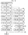
Fig. 16 is a flowchart showing a profile description
creating process.
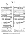
Fig. 17 is a flowchart showing a profile description
creating process.
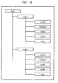
Fig. 18 is a diagram showing a hierarchical structure
of a profile.
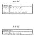
Fig. 19 is a diagram showing an example of a provider
profile.
Fig. 20 is a diagram showing an example of a consumer
profile.
Fig. 21 is a flowchart showing a profile atom
generating process.
Fig. 22 is a flowchart showing a profile atom
generating process.
Best Mode for Carrying Out the Invention
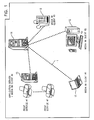
Fig. 1 shows an example configuration of a network
system according to the present invention. In the network
system, as user terminals, personal computers 11 and 12 and
PDA (Personal Digital Assistants) 13 are connected to a
media instant message server (Media IM Server) 14. Also, an
application server 15 is connected to the media IM server 14
via the Inter-net 1.
In the personal computer 11, a media IM client #1 is
implemented as middleware. In the personal computer 12, a
media IM client #2 is implemented as middleware. Similarly,
in the PDA 13, a media IM client #3 is implemented as
middleware.
In the application server 15, a media IM client #4 is
implemented as middleware. The application server 15
provides print services #1 to #7 to users accessing the
application server 15.
The media IM server 14 controls instant message
processing among these media IM clients #1 to #4.
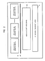
Fig. 2 shows the software configuration. In Fig. 2,
the media IM clients #1 to #4 described above are shown as
media IM client middleware 32. The media IM client
middleware 32 is provided between an IP network transport
layer 31 and an API (Application Program Interface) 33. The
API 33 executes interface processing between applications #1
to #N and the media IM client middleware 32. The media IM
client middleware 32 executes interface processing between
the API 33 and the IP network transport layer 31.
The applications #1 to #N respectively constitute
service entities.
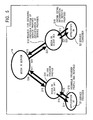
In the network system, as shown in Fig. 3, an
application that provides a service (the application #1 in
the example shown in Fig. 3) acts as a service provider 51,
and an application that receives the service (i.e., that
consumes the service) (the application #n in the example
shown in Fig. 3) acts as a service consumer 52.
The service provider 51 and the service consumer 52
execute a negotiation process for connection via media IM
clients #P1 and #C1 respectively associated therewith, using
a presence function, messaging function, or Info/Query
function of instant messaging. After confirming by the
negotiation that mutual connection is possible, the service
provider 51 and the service consumer 52 execute a connection
process by peer to peer (P2P).
The service provider 51 and the service consumer 52
respectively constitute service entities. A single
application may consist entirely of a service entity in some
cases, or consist of a set of service entities. Hereinafter,
for simplicity, it will be assumed that a single service
entity corresponds to a single application.
Next, the connection process will be described in
detail with reference to flowcharts shown in Figs. 4 to 7.
In step S1, the application #1 acting as the service
provider 51 instructs the media IM client #P1 to announce a
profile space ID representing types of services that it can
provide to buddies registered in a roster. Upon receiving
the instruction in step S2, the media IM client #P1, in step
S3, notifies the buddies that have been registered in the
roster of the profile space ID by presence.
A buddy refers to a party involved in message
communication with a user (or a media IM client) in an
instant messaging service provided by the media IM server 14.
A buddy is information represented by a user ID, a nickname
associated with a user ID, or the like, registered in
advance in the media IM server 14.
A roster refers to a list of buddies, i.e., a list of
user IDs (or nicknames) of other users (or other media IM
clients) specified by a user (or a media IM client) as
parties involved in message communication. Rosters for
respective users are unitarily managed by the media IM
server 14.
For example, if a user of the media IM client #P1 has
specified a user of the media IM client #C1 as a party
involved in message communication, the user (a user ID or
the like) of the user of the media IM client #C1 is
registered as a buddy in a roster associated with the media
IM client #P1. Conversely, if the user of the media IM
client #C1 has specified the user of the media IM client #P1
as a party involved in message communication, the user of
the media IM client #P1 is registered as a buddy in a roster
associated with the media IM client #C1.
As described above, in order to execute message
communication by instant messaging, parties involved must be
mutually registered in advance in rosters as buddies. For
example, if a first user of a media IM client has registered
a second user of another media IM client as a buddy in a
roster and if the second user has not registered the first
user as a buddy in the client of the second user, in order
to execute message communication, the first user must be
registered by the second user as a buddy in a roster prior
to message communication.
When a user has logged in (connected) to the media IM
server 14 using a media IM client, the roster is provided as
required from the media IM server 14 to the media IM client,
and is displayed in the form of a GUI (Graphical User
Interface) on a display or the like. At that time, the
media IM server 14 supplies to the media IM client icons
that allow the user to readily recognize intended buddies,
and information relating to the buddies (e.g., information
representing whether or not communication is possible), such
as presence, as well as the roster described above. The
media client, upon receiving the roster and related
information, displays the buddies in the roster in
association with the icons and presence.
It is to be understood that the rosters described above
may be managed by a server provided particularly for
unitarily managing the rosters.
Profile space IDs and application IDs are registered in
advance and managed by an administrator of an application
platform that allows negotiation of profiles at an
application level based on a presence function, messaging
function, and Info/Query function of instant messaging, such
as the network system shown in Fig. 1. Thus, the service
consumer 52 is allowed to identify contents based on the IDs.
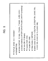
Fig. 8 shows an example of a profile space for defining
an MPEG-4 streaming server application that runs on the
personal computer 11. As shown in the figure, the profile
space is an M dimensional space that represent services
provided by the personal computer, and is constituted by a
profile space ID that serves as an ID for identifying each
profile space and M dimensional parameters. In this example,
the profile space ID is "10000001", and the parameters
include "access method", "bit rate (link speed)", "X scale",
"Y scale", and "audio codec". In this example, the value of
the access method, representing a protocol used for
communication, is 1 (RTSP/TCP+RTP/UDP) or 2 (HTTP
tunnelling). The value of the bit rate, representing a rate
of a communication line that is connected, is 6 k to 512
kbps. The value of the X scale, representing a screen size
in a horizontal direction, is 128 pixels to 352 pixels. The
value of the Y scale, representing a screen size in a
vertical direction, is 96 pixels to 288 pixels.
The access method in the profile represents a protocol
used for communication, for example, either RTSP (Real Time
Streaming Protocol)/TCP (Transmission Control Protocol) +
RTP (Real Time Transport Protocol)/UDP (User Datagram
Protocol) represented by number 1 or HTTP (Hyper Text
Transfer Protocol) tunnelling represented by number 2. The
bit rate represents a data transfer rate of a communication
line that is used. That is, the bit rate serves as
information for determining an MPEG-4 data transfer rate of
an MPEG-4 streaming service provided by the application #1.
The video codec representing a method of video
compression and expansion is MPEG-4. The audio codec
representing a method of audio compression and expansion is
one of none, CELP (Code Excited Linear Predictive) 8k, CELP
16k, AAC (Advanced Audio Coding) 16k, AAC 32k, AAC 44.1k,
and AAC 48k.
As described above, all the parameters are represented
by numeric values. Thus, the availability of a service can
be determined quickly and readily between a service provider
that provides the service and a service consumer that
receives the service (i.e., that uses the service).
Referring back to Fig. 4, upon receiving the
notification from the media IM client #P1 in step S4, the
media IM server 14, in step S5, announces the notification
to each buddy in the roster.
The media IM client #C1, which is one of the buddies
(the service consumer 52) that receive the announcement,
upon receiving the notification in step S6, determines
(verifies) in step S7 whether the profile is acceptable for
the media IM client #C1 based on the profile space ID and
the application ID of the service provider 51 (the ID of the
application #1 in this example). This is possible since, as
described earlier, each participant in the system is allowed
to identify content of the profile (functions of a device of
another party involved, as shown in Fig. 8) based on these
IDs.
For example, each of the media IM clients (i.e., the
personal computers 11 and 12, and the like) stores in
advance a table in which application IDs and profile IDs are
associated with type of parameters included in profiles and
sets of values that the parameters are allowed to take on,
and information regarding applications that act as service
consumers, as shown in Fig. 8. In step S7, the media IM
client refers to the table that it holds, identifies types
of parameters included in a profile associated with the
application ID and the profile ID obtained in step S6 and a
set of values that the parameters are allowed to take on,
and determines, based on the information that it holds
regarding the application, whether the parameters identified
(the profile associated with the parameters) are compatible
with the functions of the application that acts as a service
consumer (i.e., whether the parameters are acceptable).
The table defining association between IDs and contents
may be stored in each device (the personal computers 11 and
12, and the like), or in a predetermined server (e.g., the
media IM server 14). In that case, a user may be billed
each time the user uses the table for verification. This
allows an administrator of the media IM server 14 to earn
profit.
If the media IM client #C1 determines that the content
of the profile for which presence has been received from the
service provider 51 is acceptable for the service consumer,
in step S8, the media IM client #C1 notifies the content of
the profile (a profile associated with the profile space ID,
shown in Fig. 8) of the application #n that acts as the
service consumer 52 capable of accepting the profile. In
step S9, the application #n receives the notification from
the media IM client #C1.
Each of the media IM clients, having received the
announcement from the service provider (steps S4 to S6),
ignores the announcement if it is determined by the
verification in step S7 that an application that suitably
acts as a service consumer does not exist.
Upon receiving the content of the presence from the
service provider 51, the application #n acting as the
service consumer 52, in step S10, instructs the media IM
client #C1 to obtain detailed information of the service
provided by the service provider 51. Upon receiving the
instruction in step S11, the media IM client #C1, in step
S12, using the messaging function or Info/Query function,
requests transmission of a provider profile including a part
of or all the parameters of the parameter set of the profile
space of the service provided by the service provider 51,
described earlier. The request includes destination
information for specifying the service provider 51.
When a notification or request is issued using the
Info/Query function, as opposed to a case where the
messaging function is used, a response for acknowledgement
of reception is supplied from the recipient to the sender.
For example, when the application #1 of the media IM client
#P1 obtains a roster from the media IM server 14, the media
IM client #P1 uses the Info/Query function to supply a GET
command or the like to the media IM server 14. Upon
receiving the GET command, the media IM server 14 supplies a
response acknowledging reception to the application #1 via
the media IM client #P1 at the source of the command. By
the response, the application #1 is allowed to confirm that
the GET command has been supplied to the media IM server 14.
Since an acknowledge response is supplied from a
destination to a source at the application level as
described above, an application is allowed to send a
notification or request reliably to a destination by using
the Info/Query function.
On the other hand, when a notification or request is
issued using the messaging function, an application at a
destination that has received the notification or request
does not supply the acknowledgement response described above
to a source. Thus, an application at the source is not
allowed to grasp whether the notification or request issued
using the messaging function has been received by the
destination. Therefore, compared with the case where the
Info/Query function is used, the reliability of transmission
to an intended destination becomes lower. However, when a
notification or request is issued using the messaging
function, communication process becomes simpler compared
with the case where the Info/Query function is used, so that
processing load becomes smaller. The messaging function is
used, for example, for exchanging an instant message
(IMSTANT MESSAGING) of a text document between media IM
clients.
The notification or request by the Info/Query function,
and the notification or request by the messaging function,
described above, can be used by media IM servers as well as
media IM clients, and can be used, for example, as a
notification or request between media IM clients as well as
a notification or request between a media IM client and a
media IM server.
Furthermore, notifications or requests by the
Info/Query function or the messaging function may include
any data regardless of content, such as messages and
parameters, as well as commands.
As described above, the media IM client #P1, the media
IM client #C1, and the media IM server 14 exchange data
(including notifications, requests, and the like) using the
messaging function or the Info/Query function.
As described above, the media IM client #P1 or the like
may send a provider profile using either the messaging
function or the Info/Query function. It is to be noted that
when a provider profile is sent using the Info/Query
function, a response to the transmission of the provider
file is supplied from the destination to the source of the
transmission.
Upon receiving the request from the media IM client #C1
in step S13, the media IM server 14, in step S14, sends the
request to the media IM client #P1. Upon receiving the
request from the media IM server 14 in step S15, the media
IM client #P1, in step S16, supplies the request to the
application #1 acting as the service provider 51.
Upon receiving the request from the media IM client #P1
in step S17, the application #1, in step S18, assembles a
provider profile that is to be provided to the service
consumer 52, and sends the provider profile to the media IM
client #P1. The assembly of the provider profile will be
described later in detail with reference to flowcharts shown
in Figs. 16 and 17.
The content of the provider file generated by the
application #1 specifically sets ranges of values of
parameters that the service provider 51 can actually provide
to the service consumer 52 with consideration of runtime
environments such as network link speed and CPU load status.
Fig. 9 shows an example of a provider profile generated
as described above. In Fig. 9, the provider profile is
represented as a profile description.
Fig. 9 shows an example where the application #1 acting
as the service provider 51 only supports a viewing angle
corresponding to VGA (Video Graphics Array) (160 pixels ×
120 pixels or 320 pixels × 240 pixels), and is connected to
a network equivalent to a PHS (Personal Handyphone System)
(a network with a maximum link speed of 128 kbps). Thus, in
the example shown in Fig. 9, with consideration of the
network link speed, the viewing angle is limited only to 160
pixels × 120 pixels (X scale × Y scale) of the range defined
by the profile space shown in Fig. 8.
In the example shown in Fig. 9, the profile space ID is
"10000001", indicating that the profile description
corresponds to the profile space shown in Fig. 8. That is,
as described earlier, when the media IM client #C1 requests
a provider profile in step S12, in response to the request,
a profile description (provider profile) corresponding to
the profile space ID supplied by the media IM client #P1 in
step S3 is generated, as shown in Fig. 9.
The access method in Fig. 9 is either RTSP/TCP+RTP/UDP
or HTTP tunnelling. The bit rate is 6 kpbs to 128 kbps.
The audio codec is none or CELP 8k.
Upon receiving a response for the provider profile from
the application #1 in step S19, the media IM client #P1, in
step S20, returns the response to the application #n using
the messaging function or the Info/Query function.
Upon receiving the reply from the media IM client #P1
in step S21, the media IM server 14, in step S22, sends the
reply to the media IM client #C1. Upon receiving the reply
in step S23, the media IM client #C1, in step S24, sends the
reply to the application #n. In step S25, the application
#n receives the reply from the service provider 51
(including the provider profile shown in Fig. 9).
The application #n checks matching (performs a
comparison) between the provider profile of the service
provider 51, received by the processing in step S25, and a
consumer profile that the application #n itself generates.
The provider profile and the consumer profile described
above are generated by a process described later with
reference to flowcharts shown in Figs. 16 and 17.
As described earlier, the provider profile is a profile
created by the application #1 based on the profile space of
the content determined by the media IM client #C1 as
acceptable by the service consumer. That is, the profile
space corresponding to the provider profile is also
supported by the application #n acting as the service
consumer. Thus, the application #n is allowed to execute
the same process as in the case where the application #1
creates a provider profile, thereby creating a profile
including a part of or all the parameters in a parameter set
of the profile space supported by the service consumer (i.e.,
a consumer profile). The application #n checks matching
between the received provider profile of the service
provider 51 and the consumer profile created as described
above.
As described earlier, the provider profile (profile
description) presented by the service provider is
represented by numeric values only. Thus, the service
provider 51 is allowed to readily verify matching simply by
a one-dimensional comparison with ranges of values of
parameters included in its own profile.
A dimension herein refers to the effective number of
parameters. That is, the service consumer 52 compares, one
by one, the range of values of each parameter of the
consumer profile with the range of values of the
corresponding parameter of the provider profile.
If a part of or all of the ranges of values of the
parameters of the consumer profile overlap the ranges of
values of the corresponding parameters of the provider
profile, that is, if it is determined that a range exists in
which the service consumer 52 is capable of receiving the
service provided by the service provider 51 (the application
#n is capable of accepting data sent by the application #1),
the service consumer 52 determines that matching is
confirmed.
If matching is confirmed, the application #n, in step
S26, requests the service provider 51 to register itself
(i.e., the service consumer 52) to the service provided.
Upon receiving the request from the application #n in step
S27, the media IM client #C1, in step S28, requests the
service provider 51 for registration to the service, using
the messaging function or the Info/Query function, i.e.,
requests registration of the service consumer 52 as a
receiver of the service through registration of the
application ID of the application #n of the service consumer
52. At this time, the profile space ID and the application
ID (ID of the application #n) are included in the request.
Upon receiving the request from the media IM client #C1
in step S29, the media IM server 14, in step S30, sends the
request to the media IM client #P1. Upon receiving the
request from the media IM server 14 in step S31, the media
IM client #P1, in step S32, sends the request to the
application #1. In step S33, the application #1 receives
the registration request from the service consumer 52.
The application #1 acting as the service provider 51
registers the service consumer 52 in association with the
service provided to the service consumer 52 by the
processing in step S18. More specifically, the application
ID of the application #n of the service consumer 52 is
registered in association with the profile space ID.
The information regarding the service consumer 52,
registered as described above, is used when the application
#1 provides a service. That is, the application #1 refers
to the registered information, and provides a service to an
application of the service consumer 52 (an application
corresponding to the application ID) based on the
information.
In step S34, the application #1 instructs the media IM
client #P1 to issue a response to the request for
registration to the service, supplied from the service
consumer 52 (i.e., information indicating whether
registration of the application #n has been completed), the
request being a request for registering the application ID
of the application #n of the service consumer 52 in
association with the profile space ID to thereby register
the service consumer 52 as a receiver of the service. Upon
receiving the instruction in step S35, the media IM client
#P1, in step S36, issues a notification of a registration
result that serves as a response to the request supplied
thereto, using the messaging function or the Info/Query
function. Upon receiving the notification of the
registration result in step S37, the media IM server 14, in
step S38, sends the notification to the media IM client #C1.
Upon receiving the notification in step S39, the media IM
client #C1, in step S40, sends the notification to the
application #n. In step S41, the application #n receives
the notification of the registration result.
In step S42, the application #n determines, as a
profile atom, parameters for assuring connectivity based on
the profile description from the service provider 51 (i.e.,
the provider profile received by the processing in step S25).
That is, parameters that allow the application #n to use
data sent by the application #1 as it is (parameters
acceptable by the application #n) are determined. The
process of determining a profile atom will be described
later in detail with reference to flowcharts shown in Figs.
21 and 22.
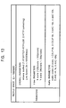
Fig. 10 shows an example of the description of the
profile atom. In this example, the profile space ID is
"10000001", indicating that the profile atom corresponds to
the profile space shown in Fig. 8. That is, as described
earlier, upon receiving a profile description (provider
profile) corresponding to the profile space ID, created and
supplied by the media IM client #P1 in response to a request
from the media IM client #C1, the media IM client #C1
creates a consumer profile corresponding to the profile
space ID, and compares the consumer profile with the
provider profile supplied thereto. If these profiles are
determined as matching, the media IM client #C1 executes
registration to the service provided, identifies ranges of
parameters for assuring connectivity from the ranges of the
respective parameters included in the profile space
corresponding to the profiles, thereby generating a profile
atom including parameters in those ranges, as shown in Fig.
10.
The access method is HTTP tunnelling. That is, as the
access method in the provider profile shown in Fig. 9,
access method associated with number 2 is selected.
The bit rate is 48 kbps, the X scale is 160, and the Y
scale is 120. The audio codec is CELP 8k.
In step S42, the application #n issues a connect
request to which the profile atom determined as described
above is attached. Upon receiving the request in step S43,
the media IM client #C1, in step S44, sends the request to
the service provider 51 using the messaging function or the
Info/Query function. Upon receiving the request in step S45,
the media IM server 14, in step S46, sends the request to
the media IM client #P1. Upon receiving the request from
the media IM server 14 in step S47, the media IM client #P1,
in step S48, sends the request to the application #1. In
step S49, the application #1 receives the request.
Upon receiving the request, the application #1, in step
S50, sends to the service consumer 52 a response including
connection information needed by the service consumer 52
(i.e., the application #n) to connect to the service
provider 51 (i.e., the application #1). The connection
information may be, for example, a URI (Uniform Resource
Identifier) representing an address of the service provider
51 that is accessed when the service consumer 52 connects to
the service provider 51 (service URI).
The response sent by the processing in step S50 by the
application #1 is received by the media IM client #P1 in
step S51. In step S52, the media IM client #P1 sends the
response to the service consumer 52 using the messaging
function or the Info/Query function. Upon receiving the
response from the media IM client #P1 in step S53, the media
IM server 14, in step S54, sends the response to the media
IM client #C1. Upon receiving the response from the media
IM server 14 in step S55, the media IM client #C1, in step
S56, sends the response to the application #n. In step S57,
the application #n receives the response.
After instructing sending of a response in step S50,
the application #1 waits for a direct access (not via the
media IM server 14) from the application #n. Thus, in step
S58, the application #n accesses the service URL (Uniform
Resource Locator) of the application #1 by peer to peer, not
via the media IM server 14. In step S59, the application #1
accepts the peer-to-peer access to the URL by the
application #n.
Thereafter, the application #1 and the application #n
are allowed to exchange information by peer to peer.
As a final result of the procedure described above, the
application #1 and the application #n exchange executable
functions in advance, so that connectivity between the
application #1 and the application #n is assured, serving to
prevent failure to exchange information.
As described above, according to the application
platform of the present invention, new protocol architecture
for allowing negotiation of profiles at the application
level is implemented based on the presence function,
messaging function, and Info/Query function of instant
messaging. Thus, by using a match making function in the
application platform, applications mounted on various
devices having different capabilities (obviously, the
capabilities may be the same), such as personal computers
and mobile devices, are allowed to connect to each other
readily and reliably. Accordingly, a system that allows
rich media information including various information such as
text, audio, music, moving pictures, and still pictures to
be transmitted by peer-to-peer communication can be
implemented. In that case, applications (service entities)
for which connectivity is finally assured are allowed to
communicate with each other by peer to peer. Accordingly, a
user is allowed to exchange information readily and reliably
without performing special operations.
The applications (service entities) described above may
be applied to commercial application servers on the Internet
1 as well as personal computers and network-enabled CE
(Consumer Electronics) devices.
For example, in the application server 15 shown in Fig.
1, an application for a commercial print service is run as a
service provider on the media IM client #4. Thus, the
personal computers 11 and 12 and the PDA 13 shown in Fig. 1
are allowed to use, via the Internet 1, the print service
provided by the application server 15, by executing the
procedure described above with the application server 15.
Thus, according to the present invention, by searching
for services provided by servers connected to the Internet 1,
a list of service providers can be displayed as a buddy list,
for example, as shown in Fig. 11.
In the example shown in Fig. 11, a list of service
providers that can be used by a print service application
acting as a service consumer on the media IM client #3
implemented on the PDA 13 is shown. In this case, by using
the presence function, status of commercial services can be
expressed in detail and flexibly in relation to service
consumers. For example, in the example shown in Fig. 11,
whether or not a commercial service is in operation is
indicated by a lamp icon 13A. In this case, for example, a
commercial service in operation is indicated by green, and a
commercial service not in operation is indicated by red.
Furthermore, in the example shown in Fig. 11, detailed
status, such as when a requested print will be finished, and
a price, is displayed as status information.
Obviously, between applications of service providers
and service consumers on user terminals, status can be
displayed on an application basis depending on the other
party involved, using a user interface and the presence
function.
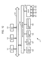
Fig. 12 shows an example configuration of the personal
computer 11. Although not shown, another personal computer
12 is similarly configured. Thus, Fig. 12 is also referred
to, when appropriate, as the configuration of the personal
computer 12.
Referring to Fig. 12, a CPU (Central Processing Unit)
121 executes various processes according to programs stored
in a ROM (Read Only Memory) 122 or programs loaded into a
RAM (Random Access Memory) 123 from a storage unit 128. The
RAM 123 also stores, as required, data needed by the CPU 121
for executing various processes.
The CPU 121, the ROM 122, and the RAM 123 are connected
to each other via a bus 124. The bus 124 is also connected
to an input/output interface 125.
The input/output interface 125 is connected to an input
unit 126 including a keyboard and a mouse, an output unit
including a display implemented by a CRT (Cathode Ray Tube)
or an LCD (Liquid Crystal Display) and a speaker, a storage
unit 128 implemented by a hard disk or the like, and a
communication unit 129 implemented by a modem, a terminal
adaptor, or the like. The communication unit 129 executes
communication processes via a network including the Internet.
Furthermore, the input/output interface 125 is
connected to a drive 130 as required. A magnetic disk 141,
an optical disk 142, a magneto-optical disk 143, a
semiconductor memory 144, or the like, is mounted as
required, and a computer program read therefrom in installed
on the storage unit 128 as required.
The application #1 (the service provider 51) and the
media IM client #P1, or the application #n (the service
consumer 52) and the media IM client #C1, described earlier,
are loaded by the CPU 121 to the RAM 123 and are then
executed.
According to the present invention, as described above,
a profile describing content of a service is provided to a
service consumer. The profile (profile description) is
expressed by M-dimensional parameters. A dimension herein
refers to the effective number of parameters. In the
example shown in Fig. 13, the profile is composed of five-dimensional
parameters (i.e., M = 5).
Fig. 13 shows a profile space of an MPEG (Moving
Picture Experts Group)-4 streaming server, which differs
from the profile space in the example shown in Fig. 8. In
the example shown in Fig. 13, parameters mainly include
three types of parameters, namely, overall parameters, video
parameters, and audio parameters. Of these parameters, the
overall parameters include access method and Link Speed, and
video parameters include X scale and Y scale. That is, the
parameters are five-dimensional parameters including access
method, Link Speed, X scale, Y scale, and audio codec. The
five dimensional parameters are identified by a profile
space ID of "10000002".
The access method in the profile represents a protocol
that is used for communication, and is either RTSP (Real
Time Streaming Protocol)/TCP (Transmission Control
Protocol)+RTP (Real Time Transport Protocol)/UDP (User
Datagram Protocol) represented by number 1 or HTTP (Hyper
Text Transfer Protocol) tunnelling represented by number 2.
The Link Speed, representing a data transfer rate of a
communication line that is used, corresponds to the bit rate
in the example shown in Fig. 8, and is a value within a
range of 6 kpbs to 100,000 kbps.
The X scale, representing a screen size along the
direction of the X axis, is within a range of 128 pixels to
352 pixels, and the Y scale, representing a screen size
along the direction of the Y axis, is within a range of 96
pixels to 288 pixels.
The audio codec, representing a method of audio
compression and expansion, is one of none represented by
number 0, CELP 8k represented by number 1, CELP (Code
Excited Linear Predictive) 16k represented by number 2, AAC
(Advanced Audio Coding) 16k represented by number 3, AAC 32k
represented by number 2, AAC 44.1k represented by number 5,
and AAC 48k represented by number 6.
As described above, all the parameters are represented
by integer values. Furthermore, if a parameter constituting
one dimension is represented as a combination of a plurality
of integer values, the following logic symbols are used.
If a parameter is represented as one of a plurality of
integer values, a logic symbol "OR" is used. "OR" is
represented using a delimiter [ |], such as [ k] |[ m] |[ n].
This means that the parameter is one of k, m, and n. In
this case, k, m, and n are integers, and are ordered from
smaller to larger (i.e., k < m < n).
For example, as will be described later with reference
to Fig. 15, the access method is "1|2", which indicates that
the access method is either 1 (RTSP/TCP+RTP/UDP) or 2 (HTTP
tunnelling).
When a parameter is represented by an integer value
within a predetermined range, a logic symbol ":"
representing the range is used. A range is represented, for
example, as [ m] :[ n] #[ k]. [ m] represents a start value and
[ n] represents an end value. [ m] and [ n] cannot be omitted.
Furthermore, obviously, the start value [m] is less than or
equal to the end value [ n]. #[ k] represents a step defining
a change width between the start value [ m] and the end value
[ n], and is a natural number and a multiple of 1 as a base
unit of normalization. [ k] may be omitted.
For example, if the video X axis is represented as
"8:22#2", it is meant that the video X axis is one of (8, 10,
12, 14, 16, 18, 20, 22). That is, assuming that the base
unit of normalization is 16 pixels, (assuming that 16 pixels
corresponds to k = 1), the representation represents a set
of values sampled at an interval of 32 pixels (corresponding
to k = 2) from 128 pixels to 352 pixels.
A description including a combination of a range and
"OR" is prohibited, since otherwise it becomes impossible to
readily determine whether a service can be received. A not-applicable
(N/A) parameter is represented by null (,,).
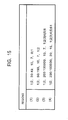
Furthermore, when a profile is described specifically,
each parameter is normalized by a base unit that is
predetermined as a unit of normalization. As shown in Fig.
14, the base unit for Link Speed is kbps, and the base unit
for X scale and Y scale is 16 pixels. Thus, 128 pixels to
352 pixels for X scale, shown in Fig. 13, is represented as
8 to 22 when normalized by 16 pixels, and 96 pixels to 288
pixels for Y scale is represented as 6 to 18.
The standard method for describing parameters has been
described above. Furthermore, customized description may be
added in the form of an XML (extensible Markup Lunguage)
document.
Furthermore, elements constituting dimensions may be
added as needed. For example, in the example shown in Fig.
13, audio codec is one of seven values represented by
numbers 0 to 6. However, other elements represented by
numbers 7 and 8 may be added as extension.
It is to be noted that when some elements are added,
backward compatibility must be assured. That is, it is
required that a device that does not have audio codec
elements represented by numbers 7 and 8 be able to use a
profile space with a profile space ID of "10000002".
Accordingly, it is assured that each device is capable of
determining content based on a profile space ID. Thus, even
if the number of elements constituting each dimension is
increased, each device is able to determine content based on
a profile space ID (compatibility is assured), so that the
profile space ID is not changed. On the other hand, if the
number of dimensions is increased, each device is not
allowed to determine content based on a profile space ID
(compatibility is not assured), so that the profile space ID
is changed.
Furthermore, according to the present invention,
profiles can be created separately for a plurality of
regions based on a main-factor parameter that is most likely
to restrict coexistence with other parameters.
What is meant by "to restrict coexistence with other
parameters" is that when a parameter takes on a certain
value, combination with other parameters is inhibited.
According to the present invention, link speed is a main-factor
parameter.
For example, when a user is allowed to select an
arbitrary value for Link Speed and an arbitrary value for
audio codec, it is possible that an environment that is not
actually achievable or infeasible is defined. For example,
if a personal computer that is connected to an analog
telephone line with a link speed below 50 kbps selects AAC
44. 1 k represented by number 5 or AAC 48 k represented by
number 6 as audio codec, such a relationship is actually
infeasible.
Thus, according to the present invention, as shown in
Fig. 15, regions are separated as a first region (region
denoted as (1)) with a link speed below 50 kbps (49 kbps),
as in the case of an analog telephone circuit, a second
region (region denoted as (2)) with a link speed not lower
than 50 kbps and below 200 kbps (not larger than 199 bps),
as in the case of an ISDN (Integrated Service Digital
Network) or PHS, a third region (region denoted as (3)) with
a link speed not smaller than 200 kbps, such as 1.5 Mbps or
8 Mbps in the case of ADSL (Asymmetric Digital Subscriber
Line). Furthermore, a fourth region (region denoted as (4))
is defined as a region in a case where link speed is not
smaller than 200 kbps and where the capability of the CPU
(Central Processing Unit) of the device is high.
In the example shown in Fig. 15, in the first region,
access method is either 1 or 2, and link speed is 35 kbps to
49 kbps. X scale is 10, and Y scale is 7. Audio codec is
either 0 or 1.
In the second region, access method is either 1 or 2,
link speed is 50 kbps to 199 kbps. X scale and Y scale are
10 and 7, respectively, as in the first region. Audio codec
is either 1 or 2.
In the third region, access method is either 1 or 2,
link speed is 200 kbps to 100,000 kbps. X scale is 10, and
Y scale is 7. Audio codec is one of 1 to 6.
In the fourth region, access method is either 1 or 2,
and link speed is 200 kbps to 100,000 kbps, as in the third
region. X scale is 20, and Y scale is 15. Audio codec is
one of 1 to 6.
In each of the regions, each of the five-dimensional
parameters is defined as a one-dimensional integer value,
i.e., as a single numeric value.
The number of divisions of profiles (number of regions)
may be determined arbitrarily by each service provider.
Also, the value of a profile description (values of
constituting elements of each dimension in each region) may
be determined arbitrarily by a service provider.
It is to be noted that even when the number of regions
is changed, profile space IDs are not changed.
As described above, when regions are divided into a
plurality of regions based on a main-factor parameter, in
each region, whatever values.of the five-dimensional
parameters are set by a service consumer, an environment
that is infeasible or impossible is not set. Therefore, a
service consumer is allowed to select a region from a
plurality of regions and to select arbitrary values as
appropriate from the parameters of the five dimensions in
that region.
More specifically, in the processing in step S25
described earlier with reference to Fig. 5, upon receiving a
provider profile (profile description) of the service
provider 51, the service consumer 52 compares the values of
the main-factor parameter (link speed) described in the
respective regions of the provider profile with the main-factor
parameter of its own consumer profile to extract a
region where a match exists. As described earlier, since
the main-factor parameter is represented by an integer,
whether a matching range exists can be readily determined by
a simple integer calculation.
When parameters are not divided into regions as opposed
to the case described above, the service consumer 52 is not
allowed to select an applicable service without using a
program involving complex conditional branching.
As described above, a service is represented by a space
constituted by M dimensional parameters. Individual spaces
are identified by profile space IDs. Parameters
constituting an individual space are represented by
combinations of integer values and logic symbols. As logic
symbols, "OR" representing selection of one of a plurality
of integer values, and "range" representing a set of integer
values, are used. By representing a service using such a
data structure, whether a service can be used can be quickly
and readily determined between a service provider that
provides a service and a service consumer that receives the
service (that uses the service).
Next, a process in which the service provider 51
(application #1) creates a profile (profile description) to
be provided to the service consumer 52 (application #n) will
be described with reference to flowcharts shown in Figs. 16
and 17. This process corresponds to the process of
assembling a provider profile in step S18 shown in Fig. 5.
Now, let it be supposed that the application #1
generates a provider profile (profile relating to its own
functions) with a profile space ID of "10000002", shown in
Fig. 13. Let it also be supposed that the application #1 is
connected to an ADSL line of 8 Mbps, with a link speed of
4,800 as a main-factor parameter, determined from an actual
throughput of the line (CurrentLinkSpeed), with a VGA (Video
Graphics Array) video display system, and with a relatively
low CPU processing capability.
In the steps described below, the application #1 checks
it own capabilities (functions) associated with each region,
and sets values corresponding to its own capabilities
associated with each region. Thus, in the steps described
below, specific values set to parameters are values
corresponding to its own capabilities associated with each
region. The application #1 may check its own capabilities
in each step, or read its own capabilities checked and
stored in advance.
In step S71, the application #1 sets the value
"10000002" of the profile space ID currently being
considered in a variable PSId for setting a parameter.
Then, in steps S72 to S78, parameters relating to the
first region are set. In steps S79 to S85, parameters
relating to the second region are set. In steps S86 to S92,
parameters relating to the third region are set. In steps
S93 to S98, parameters relating to the fourth region are set.
In step S72, the application #1 sets a value "1" in a
variable PSId.region indicating that the region is the first
region.
More specifically, as shown in Fig. 18, a profile with
a profile space ID of "10000002" is configured under PSId
(profile space ID) as a root, with each region (Region)
being constituted of parameters access (Access Method),
linkSpeed (Link Speed), xScale (X scale), yScale (Y scale),
and audio (Audio Codec). The tree structure described above
will hereinafter be described using a "." to delimit layers,
such as PSId.region.access.
Thus, more specifically, "10000002.1" is set in
PSId.region. In Figs. 16 and 17, however, in order to avoid
lengthy description, only parameters that are newly set are
shown.
In step S73, the application #1 sets {1|2} representing
1:RTSP/TCP+RTP/UDP or 2:HTTP tunnelling as Access Method in
PSId.region.access. This is because, as described earlier,
the application #1 has a function for carrying out
communication using "RTSP/TCP+RTP/UDP" and also has a
function of carrying out communication using "HTTP
tunnelling". If the application #1 only has a function of
carrying out communication using "RTSP/TCP+RTP/UDP" (i.e.,
does not have a function of carrying out communication using
"HTTP tunneling"), the application #1 sets {1} representing
1:RTSP/TCP+RTP/UDP as Access Method in PSId.region.access.
In step S74, the application #1 sets {39:49}
representing 30 kbps to 49 kbps in PSId.region.linkSpeed as
Link Speed. This is because the first region is being
considered for processing and the default link speed for the
first region is 30 kbps to 49 kbps. (Thus, as will be
described later, in the processing in steps S81, S88, and
S95 associated with the second to fourth regions, 50 kbps to
199 kbps, 200 kbps to 100,000 kbps, and 200 kbps to 100,000
kbps, which are default link speeds for the respective
regions, are set, respectively.)
In step S75, the application #1 sets {10} representing
160 pixels in PSId.region.xScale as Xscale, and sets { 7}
representing 114 pixels in PSId.region.yScale as Y scale.
These values are based on functions of the application #1,
relating to viewing angles for displaying images.
In step S76, the application #1 sets {0|1} representing
0:none or 1:CELP 8k as audio Codec in PSId.region.audio.
This is because the application #1 supports both the
functions of 0:none and 1:CELP 8k as audio Codec.
Then, in step S77, the application #1 compares the
value of current speed (Current Link Speed) representing the
effective throughput of a line to which the application #1
is connected with the lower limit of the subsequent second
region, i.e., 50 kbps, to determine whether the current
speed is smaller than the lower limit. If the current link
speed is smaller than 50 kbps, second and higher regions
cannot be defined, so that the process proceeds to step S78.
In step S78, the application #1 again sets
{30:CurrentLinkSpeed} representing values from 30 kbps to
the current link speed (CurrentLinkSpeed) in
PSId.region.linkSpeed as Link Speed. That is, the value
{30:49} set in the processing of step S74 is updated.
Accordingly, a maximum value possible is set as a parameter.
In this case, CurrentLinkSpeed of the application #1 is
4,800 kbps, which is larger than 50 kbps. Thus, the process
proceeds to step S79, in which parameters for the second
region are set.
In step S79, the application #1 sets a value "2"
representing the second region in PSId.region. More
specifically, "10000002.2" is set in PSId.region.
In step S80, similarly to step S73, the application #1
sets {1|2} in PSId.region.access as Access Method.
In step S81, the application #1 sets {50:199}
representing 50 kbps to 199 kbps in PSId.region.linkSpeed as
Link Speed.
In step S82, similarly to step S75, the application #1,
sets {10} in PSId.region.xScale as X Scale, and sets {7} in
PSId.region.yScale as Y Scale.
In step S83, the application #1 {1|2} representing
1:CELP 8k or 2:CELP 16k in PSId.region.audio as Audio Codec.
In step S84, the application #1 compares the value of
CurrentLinkSpeed with the lower limit of the subsequent
third region, i.e., 200 kbps, to determine whether the value
of CurrentLinkSpeed is smaller than the lower limit. If the
value of CurrentLinkSpeed is smaller than 200 kbps,
parameters for the third region cannot be set. Thus, the
process proceeds to step S85, in which the application #1
again sets {50:CurrentLinkSpeed} in PSId:region:linkSpeed as
Link Speed. That is, the value {50:199} set in step S81 is
updated.
If it is determined in step S84 that the value of
CurrentLinkSpeed is larger than 200 kbps, the process
proceeds to step S86, in which parameters for the third
region are set. In this case, the value of CurrentLinkSpeed
is 4,800 kbps, so that the application #1 determines NO, and
processing in step S86 and subsequent steps are executed.
In step S86, the application #1 sets a value "3" for
the third region in PSId.region. More specifically, a value
of "10000002.3" is set in PSId.region.
In step S87, similarly to step S80, the application #1
sets {1|2} in PSId.region.access as Access Method.
In step S88, the application #1 sets {200:100000}
representing 200 kbps to 100,000 kbps in
PSId.region.linkSpeed as Link Speed.
In step S89, similarly to step S82, the application #1
sets {10} in PSId.region.xScale as Xscale, and sets {7} in
PISd.region.yScale as Y Scale.
In step S90, the application #1 sets {1|2|3|4|5|6}
representing 1:CELP 8k, 2:CELP 16k, 3: AAC 16k, 4: AAC 32k,
5: AAC 44.1 k, or 6: AAC 48k in PSId.region.audio as Audio
Codec.
In step S91, the application #1 determines whether or
not the capability of the CPU is low as a condition for
setting parameters for the subsequent fourth region. The
CPU capability is determined as low if a clock frequency
thereof is lower than a predetermined reference frequency
(e.g., 800 MHz) or a predetermined type of CPU (e.g.,
Pentium® 4).
In this case, the CPU of the application #1 has a low
capability, so that step S91 evaluates to YES. Then, in
step S92, Link Speed for the third region is updated. Thus,
Link Speed that has been set to be {200:CurrentLinkSpeed} is
again set in PSId.region.linkSpeed. That is, the value of
"200:1000000} set by the processing in step S88 is updated
to a maximum value possible.
If it is determined in step S91 that the CPU capability
is not low (i.e., it is high) (i.e., the clock frequency is
800 MHz or higher, or the functionality of the CPU is
equivalent to that of Pentium® 4 or higher), the process
proceeds to step S93, in which parameters for the fourth
region are set.
In step S93, the application #1 sets a value "4"
representing the fourth region in PSId.region. More
specifically, "10000002.4" is set.
In step S94, similarly to step S87, the application #1
sets {1|2} in PSId.region.access as Access Method.
In step S95, similarly to step S88, the application #1
sets {200:100000} in PSId.region.linkSpeed as Link Speed.
In step S96, the application #1 sets {20} representing
320 pixels in PSId.region.xScale as X scale, and sets {15}
representing 240 pixels in PSID.region.yScale as Y scale.
In step S97, similarly to step S90, the application #1
sets {1|2|3|4|5|6} in PSId.region.audio as Audio Codec.
Finally, in step S98, the application #1 again sets
{200:CurrentLinkSpeed} in PSId.region.linkSpeed as Link
Speed. That is, the value {200:100000} set by the
processing in step S95 is updated.
Fig. 19 shows the provider profile (provider profile
description) of the application #1 acting as the service
provider 51, set as described above. As shown in the figure,
in this case, parameters for the three regions have been set
by the processing in steps S71 to S92 described above. The
parameters that have been set have the values described with
reference to Figs. 16 and 17.
The profile description creating process shown in Figs.
16 and 17 is also executed by the application #n acting as
the service consumer 52. However, specific values of the
parameters mentioned in the steps shown in Figs. 16 and 17
are for the application #1, not for the application #n, so
that values set in the steps differ.
For example, let it be supposed that the application #n
acting as the service consumer 52 is connected to an ISDN
line of 64 kbps, which is relatively slow, and that
CurrentLinkSpeed representing the effective throughput is 48
kbps. In this case, when the profile description creating
process shown in Figs. 16 and 17 are executed, only
processing for the first region in steps S71 to S78 is
executed. That is, since the value of CurrentLinkSpeed (48
kbps) is smaller than 50 kbps, step S77 evaluates to YES,
and processing in step S79 and subsequent steps is not
executed.
That is, in this case, the application #n sets
"10000002" in PSId in step S71, and sets a value "1"
representing the first region in PSId.region in step S72.
More specifically, "10000002.1" is set in PSId.region.
In step S73, the application #n sets {1|2} in
PSId.region.access as Access Method.
In step S74, the application #n sets {30:48} in
PSId.region.linkSpeed as Link Speed.
In step S75, the application #n sets {10} in
PSId.region.xScale as X Scale, and sets {7} in
PSId.region.yScale as Y Scale.
In step S77, the value of CurrentLinkSpeed, which is 48
kbps, is determined as smaller than 50 kbps. Thus, in step
S78, the application #n again sets {30:CurrentLinkSpeed} in
PSId.region.linkSpeed as Link Speed. That is, the value
{30:49} set in step S74 is updated.
Fig. 20 shows the consumer profile (consumer profile
description) generated by the application #n as described
above. As shown in the figure, the first region is the only
region. Parameters set in this region have values set by
the processing in steps S71 to S78 described above.
When the application #n has the consumer profile shown
in Fig. 20, upon receiving the provider profile shown in Fig.
19, transmitted from the application #1, in step S26 shown
in Fig. 6, the application #n determines whether link speed
30:48 (Fig. 20) as the main-factor parameter of the consumer
profile has a matching part with the value of the main
parameter of the provider profile. In the provider profile
shown in Fig. 19, link speed for the first region is 30:49,
link speed for the second region is 50:199, and link speed
for the third region is 200:4800. Thus, it is determined
that a matching part (overlapping part) exists in at least
one region (the first region) (the range of 30 to 49
overlaps the range of 30 to 48, at values of 30 to 48).
Thus, as described above, in step S26 shown in Fig. 6, the
application #n executes a registration request process for
the service provided, and then creates a profile atom in
step S42.
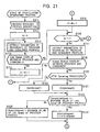
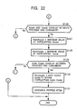
Next, the profile atom generating process will be
described with reference to flowcharts shown in Figs. 21 and
22. This process corresponds to the processing executed in
step S42 shown in Fig. 7.
In this process, first, by the processing of steps S111
to S115, a region is selected from parameter sets for
respective region, presented by a service provider, with
consideration of Link Speed (main-factor parameter) of a
network connected to a service consumer.
More specifically, in step S111, the application #n
receives the provider profile description (Fig. 19)
transmitted from the application #1. This processing
corresponds to the processing in step S41.
Then, in step S112, the application #n initializes an
internal variable N to 0. In step S113, the application #n
extracts parameters of (N+1)-th region (in this case, the
first region, since N = 0) from the provider profile
received by the processing in step S111 and the consumer
profile (Fig. 20) created by executing the processes shown
in Figs. 16 and 17.
In step S114, the application #n determines whether
Link Speed of the region extracted by the processing in step
S113 overlaps. In this case, it is determined whether Link
Speed of the first region overlaps. If Link Speed does not
overlap, the process proceeds to step S116, in which it is
determined whether the value N is a value other than 0. In
this case, the value N is 0, so that step S116 evaluates to
NO. That is, in this case, since no region with overlapping
Link Speed exists, the application #n is not allowed to
communicate with the application #1. The process is then
exited.
In the example shown in Figs. 19 and 20, Link Speed for
the first region in Fig. 20, i.e., 30:48, overlaps Link
Speed for the first region in Fig. 19, i.e., 30:49. Thus,
the process proceeds to step S115, in which the application
#n increments the value of the variable N by 1 (in this case,
N = 1).
The process then returns to step S113, in which the
application #n extracts parameters of the provider profile
and the consumer profile for the (N+1)-th region (in this
case, the second region, since N = 1).
In step S114, the application #n, of the parameters
extracted by the processing in step S113, determines whether
Link Speed overlaps. If Link Speed for the second region
overlaps, the process proceeds to step S115, in which the
value of the variable N is further incremented by 1 (in this
case, N = 2).
Then, in step S113, the provider profile and the
consumer profile for the (N+1)-th region (in this case, the
third region, since N = 2) are read. In step S114, it is
determined whether Link Speed among the parameters extracted
in step S113 overlaps. If it is determined that an overlap
exists, the process again proceeds to step S115, in which
the value of the variable N is incremented by 1 (in this
case, N = 3).
As described above, all regions having overlapping Link
Speed are extracted by repeatedly executing the processing
in steps S113 to S115. If corresponding regions no longer
exist in the provider profile and the consumer profile, or
even if corresponding regions exist, if Link Speed does not
overlap, the process proceeds from step S114 to step S116,
in which it is determined whether the value N is a value
other than 0. In this case, the value N corresponds to the
number of a region having a largest number (region having
highest function) among the regions having overlapping Link
Speed. Thus, when at least one region having overlapping
Link Speeds exists, the value N is a value other than 0.
In that case, the process proceeds to step S117, in
which the application #n extracts parameters of the provider
profile and the consumer profile for the N-th region. In
step S118, the application #n determines whether Access
Method of the provider profile and Access Method of the
consumer,profile, extracted by the processing in step S117,
overlap.
In the example shown in Figs. 19 and 20, Access Method
for the first region is both {1|2}, so that it is determined
that Access Method overlaps. If it is determined that
Access Method does not overlap, the process proceeds to step
S119, in which the value of the variable N is decremented by
1. That is, the region being considered for processing is
changed to a region having a number that is smaller by 1.
Then, in step S116, it is determined whether the value N is
a value other than 0. If it is determined that the value N
is not a value other than 0, i.e., the value N is 0, it
indicates that a profile atom is not found after all. Then,
the process is exited.
As described above, if at least one parameter without
overlapping exists among the five dimensional parameters,
the processing target is moved to a region with a number
that is immediately below. Similarly, when it is determined
that X scale and Y scale do not overlap in step S126, which
will be described later, or when it is determined that Audio
does not overlap in step S129, the processing target is
moved to a region with a number immediately below.
In the example shown in Figs. 19 and 20, Access Method
for the first region are both {1|2}, so that the parameters
overlap. Thus, the process proceeds to step S120, in which
the application #n determines whether HTTP Tunnelling is
selected as a priority. When a firewall exists in the path
to the Internet, HTTP Tunnelling is selected as a priority.
In this case, the process proceeds to step S121, in
which the application #n sets {2} in AtomAccess, which is
Access Method for the profile atom (Fig. 13). On the other
hand, if it is determined in step S120 that HTTP Tunnelling
is not a priority, the application #n sets {1} in AtomAccess
in step S122 (Fig. 13).
After the processing in step S121 or step S122, the
process proceeds to step S123, in which the application #n
determines whether the value of CurrentLinkSpeed is less
than or equal to the maximum value of LinkSpeed in the
provider profile. If the value of CurrentLinkSpeed
representing the effective throughput of the line connected
to the application #n is not larger than the maximum value
of Link Speed parameter in the provider profile, the
application #n sets the value of CurrentLinkSpeed in
AtomLinkSpeed in step S124.
On the other hand, if it is determined in step S123
that the value of CurrentLinkSpeed is greater than the
maximum value of Link Speed, the application #n sets the
maximum value of LinkSpeed of the provider file in
AtomLinkSpeed in step S125.
For example, if CurrentLinkSpeed is 48 kbps and the
maximum value of LinkSpeed parameter of the provider file is
49 kbps, {48} is set in AtomLinkSpeed of the profile atom in
step S125.
In step S126, the application #n determines whether X
scale parameters and Y scale parameters overlap between the
provider profile and the consumer profile. If overlapping
does not exist between these profiles, as described earlier,
the process proceeds to step S119, in which the value N is
decremented by 1, and the process enters processing
involving a region with a number smaller by 1.
If it is determined in step S126 that X scale
parameters and Y scale overlap, in step S127, the
application #n sets the maximum overlapping value of X scale
in AtomXscale, which is X scale for the profile atom.
Furthermore, in step S128, the application #n sets the
maximum overlapping value of Y scale in AtomYscale, which is
Y scale for the profile atom.
For example, if the maximum value of X scale is 160
pixels (10 × 16 pixels) for both the provider profile and
the consumer profile, and if the maximum value of Y scale is
112 pixels (7 × 16 pixels) for both the provider profile and
the consumer profile, {10} is set in AtomXscale of the
profile atom and {7} is set in AtomYscale of the profile
atom.
In step S129, overlapping of Audio Codec between the
provider profile and the consumer profile is checked. If
overlapping does not exist between these profiles, as
described earlier, the process proceeds to step S119, in
which the value N is decremented by 1, and the process
enters processing for a region with a number smaller by 1.
If it is determined in step S129 that Audio Codec
overlaps between the provider profile and the consumer
profile, the process proceeds to step S130. In step S130,
the application #n selects the best audio quality within
overlapping Audio Codec and sets it as AtomAudio, which is
Audio Codec for the profile atom. In this example, Audio
Codec written in profiles are numbered so that the values
become larger in order of lower audio quality to higher
audio quality. Thus, high audio quality is selected by
selecting a largest number among overlapping Audio Codec.
For example, if Audio Codec is 0: None or 1: CELP 8k for
both the provider profile and the consumer profile, {1} is
set in AtomAudio of the profile atom.
In step S131, the application #n creates (assembles) a
profile atom based on the values of parameters of the
profile atom, determined by the processing in the steps
described above.
By the processing in step S42 shown in Fig. 7, the
application #1 is notified of the profile atom generated as
described above.
As described above, according to the present invention,
M-dimensional parameters relating to a service, the
parameters being represented as numeric values, are obtained,
and detailed information representing content of the service
by the parameters is generated. Accordingly, the content of
the service can be readily recognized, so that two
apparatuses are allowed to exchange information quickly and
reliably via a network.
By normalizing the parameters by base units, detailed
information can be represented by smaller values. This
facilitates processing for comparison.
By dividing the parameters into a plurality of regions,
parameters that allow information to be actually transferred
simply without using a complex algorithm can be selected.
By representing the parameters as one-dimensional
values, the parameters can be readily compared.
By representing detailed information using a
combination of integer values and logic symbols, parameters
can be represented in a format that readily allows
comparison.
By using, as logic symbols, a first symbol representing
selection of one of the plurality of integer values and a
second symbol representing a set of the integer values,
parameters can be represented in a format that readily
allows comparison.
By using, as the second symbol, a start value
representing a start of a range, an end value representing
an end of the range, and a step defining a change width
between the start value and the end value, the range can be
represented in a format that readily allows comparison.
When service is a service of sending or receiving data
via a network, information needed by two apparatuses for
exchanging information quickly and reliably can be exchanged.
By attaching an identifier to detailed information, the
detailed information can be readily identified.
By sending an identifier to a destination via a network,
the destination is allowed to readily identify detailed
information.
By sending detailed information associated with an
identifier to a destination and receiving M-dimensional
parameters sent from the destination, detailed information
need not be sent from the beginning, allowing reliable
exchange of information while efficiently using the
transmission path.
By receiving an identifier sent via a network, detailed
information can be readily recognized.
By requesting sending of detailed information
associated with an identifier received, useless exchange of
detailed information with a party with which communication
is not possible is prevented.
By using a data structure including M-dimensional
parameters and representing the parameters by combinations
of integer values and logic symbols, data can be described
in a format such that content can be readily recognized.
Although M:5 in the above description, the dimensions
may be larger or smaller than that.
Furthermore, although the above description has been
made in the context of an example of a service of providing
AV data, the present invention can be applied to cases where
various services are provided and used as well as the
service of providing AV data.
The processing described above may be executed by
hardware in the case of network-enabled CE equipment or the
like. Obviously, the processing may be executed by software.
When the series of processes are executed by software,
programs constituting the software are installed from a
network or a recording medium onto a computer included in
special hardware, a general-purpose computer or the like
that is capable of executing various functions with various
programs installed thereon.
The recording medium may be a package media carrying
the programs, provided to a user for providing programs
separately from a main unit of the apparatus, such as a
magnetic disk 141 (including a floppy disk), an optical disk
142 (including a CD-ROM (Compact Disk-Read Only Memory) and
a DVD (Digital Versatile Disk)), a magneto-optical disk 143
(including an MD (Mini-Disk)), or a semiconductor memory 144.
Alternatively, the recording medium may be the ROM 122 or a
hard disk included in the storage unit 128, carrying the
programs, provided as included in advance in the main unit
of the apparatus.
In this specification, steps defining the programs
recorded on the recording medium may include processes that
are executed sequentially in the orders described, and also
include processes that are executed in parallel or
individually, not necessarily sequentially.
In this specification, a system refers to the entirety
of apparatuses constituted of a plurality of apparatuses.
Industrial Applicability
As described hereinabove, according to a first
invention, information representing content of a service can
be generated. In particular, detailed information that
allows content of a service to be readily confirmed can be
generated. Accordingly, it is assured that content of a
service is communicated to the other party, serving to form
a connection with an apparatus of the other party quickly
and reliably and to exchange data.
According to a second invention, content of a service
can be represented. In particular, content of a service can
be represented such that it can be readily confirmed.
Accordingly, it becomes possible to confirm content of a
service reliably, serving to form a connection with an
apparatus of the other party quickly and reliably and to
exchange data.