TECHNICAL FIELD
-
Embodiments in accordance with the invention generally relate to the field of imaging.
More specifically, embodiments in accordance with the invention pertain to functional
imaging.
BACKGROUND ART
-
Functional imaging is a term of art that in general refers to techniques in which the aim
is to extract quantitative information about physiological function from image-based data.
Optical coherence tomography (OCT) is an imaging modality that can resolve much smaller
features than ultrasound, and overcomes issues associated with the scatter of visible and near-visible
light in human tissue that make other forms of optical imaging quite difficult.
-
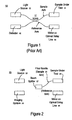
In conventional fiber-based OCT, an interferometer is used to collect image data of a
sample under test. Figure 1 is a block diagram of a prior art apparatus 10 that exemplifies a
Michelson interferometer. Light from light source 12 travels through a single-mode optical
fiber to beam splitter 17, typically a 50/50 beam splitter. Beam splitter 17 directs a portion of
the light along a single-mode optical fiber sample arm to the sample under test 14, with the
remainder of the light directed along a single-mode optical fiber reference arm to the mirror
18. Sample under test 14 is, for example, a fiber-optic device or human tissue. The delay line
with a mirror 18 increases the optical length of the reference arm. By moving the mirror back
and forth, reflection data can be collected at different depths within sample under test 14.
Light reflected from sample under test 14 is received by photon detector 16, as is light
reflected from the moveable mirror 18. Photon detector 16 has just one spatial channel (that is,
a single large pixel).
-
To obtain an image, the sample arm optical fiber is placed at a location in (or on) the
sample. A depth scan is obtained at that location. The optical fiber is then moved to an
adjacent location and another depth scan is obtained. The process is repeated laterally across
the sample, with a depth scan performed at each lateral location. A scan of one line can be
referred to as a transverse scan. To create a two-dimensional image of a sample, transverse
scans are performed over the area of the sample.
-
The process of performing depth scans and transverse scans on a sample can be time-consuming.
If each depth scan takes 0.01 seconds and 1000x1000 depth scans are performed
across the area of the sample, then approximately three hours are needed to complete the
measurements.
-
En-face imaging with a free-space reflectometer and lamp source provides an approach
for speeding up the collection of information. En-face images are planar images of the sample,
captured simultaneously using parallel optical channels in the sample arm of a device like
apparatus 10. In this case, the beam splitter may be a bulk optic free space beam splitter, and
the optical signals may propagate in free space within some or all of the arms rather than in
optical fibers. Moving the location of the reflector in the reference arm changes the optical
depth at which image information is collected. Image information can be collected in two
dimensions simultaneously and thus more rapidly. However, lateral scatter of photons from
adjacent sample locations can reduce contrast. Thus, en-face imaging, while speeding up
image collection, can reduce image quality.
-
Accordingly, a functional imaging system and/or method that addresses the problems
described above would be of value.
SUMMARY OF THE INVENTION
-
The invention provides, in various embodiments, methods and apparatus for en-face
imaging using multiple wavelengths. In general, an imaging system receives light reflected
from a sample under test and distinguishes between reflected light at a first wavelength and
reflected light at a second wavelength. The imaging system can include first regions for
detecting light of a first wavelength while blocking light of a second wavelength and second
regions for detecting light of the second wavelength. Each of the first and second regions may
correspond to a respective pixel of a single imager, interleaved in a pattern. Alternatively, the
first regions may be part of a first imager and the second regions may be part of a second
imager. Images at both wavelengths are collected simultaneously.
-
En-face images are output using en-face image data corresponding to the first
wavelength and en-face image data corresponding to the second wavelength. En-face images
can be collected with higher contrast by, for example, taking the difference between the en-face
image corresponding to the first wavelength and the en-face image data corresponding to
the second wavelength.
BRIEF DESCRIPTION OF THE DRAWINGS
-
The accompanying drawings, which are incorporated in and form a part of this
specification, illustrate embodiments in accordance with the invention and, together with the
description, serve to explain the principles of the invention. The drawings referred to in this
description should not be understood as being drawn to scale except if specifically noted.
- Figure 1 is a block diagram of a prior art apparatus for collecting image data.
- Figure 2 is a block diagram of one embodiment of an en-face imaging system in
accordance with the invention.
- Figure 3 is a block diagram of a second embodiment of an en-face imaging system in
accordance with the invention.
- Figure 4 is a block diagram of one embodiment of a reflective imaging system in
accordance with the invention.
- Figure 5 is a block diagram of a second embodiment of a reflective imaging system in
accordance with the invention.
- Figure 6 is a block diagram of one embodiment of a transmissive imaging system in
accordance with the invention.
- Figure 7 illustrates one embodiment of an imager in accordance with the invention.
- Figure 8 is a graph illustrating transmission characteristics of different filters that can
be used by embodiments in accordance with the invention.
- Figure 9 is a block diagram of another embodiment of an en-face imaging system in
accordance with the invention.
- Figure 10 is a flowchart of an embodiment of a method for en-face imaging using
multiple wavelengths in accordance with the invention.
-
DETAILED DESCRIPTION OF THE INVENTION
-
Reference will now be made in detail to the various embodiments in accordance with
the invention, examples of which are illustrated in the accompanying drawings. While the
invention will be described in conjunction with these embodiments, it will be understood that
they are not intended to limit the invention to these embodiments. On the contrary, the
invention is intended to cover alternatives, modifications and equivalents, which may be
included within the spirit and scope of the invention as defined by the appended claims.
Furthermore, in the following detailed description of the present invention, numerous specific
details are set forth in order to provide a thorough understanding of the present invention. In
other instances, well-known methods, procedures, components, and circuits have not been
described in detail as not to unnecessarily obscure aspects of the present invention.
-
Figure 2 is a block diagram of an apparatus 20 for en-face imaging of a sample under
test 24 using multiple wavelengths of light in one embodiment in accordance with the
invention. En-face images are planar images of the sample, captured simultaneously. En-face
image data can be thought of as representing the image generated at a two-dimensional plane
that intersects the sample under test 24.
-
In the embodiment of Figure 2, apparatus 20 includes a light source 22, an imaging
system 26, a beam splitter 27, and a mirror on an optical delay line 28. Apparatus 20 includes
or is coupled to an imaging system 26. Apparatus 20 can include other elements in addition to
those discussed herein.
-
Aspects of apparatus 20 (e.g., light source 22, beam splitter 27 and mirror on optical
delay line 28) can be implemented in a reflectometer or an interferometer such as a Michelson
interferometer. An overview of these elements (e.g., light source 22, a beam splitter 27 and
mirror on optical delay line 28) is provided below; however, more detailed descriptions of the
elements and the operation of an interferometer are not provided, as the principles and features
of interferometers are well known in the art.
-
Light source 22 is an incoherent light source that transmits light at two or more
different wavelengths. In one embodiment, light source 22 includes a source of white light in
combination with a diffuser, as this provides an inexpensive source of incoherent light relative
to other types of light sources. Use of a white light source may engender the use of filter(s) to
eliminate or block wavelengths other than the wavelengths selected for use; refer to Figure 8.
Other types of lights sources, such as edge emitting light emitting diodes (EELEDs) or low
coherence superluminescent light emitting diodes (SLDs), can be used. Light source 22 can
include an aiming beam. Also, multiple light sources can be used. Multiple light sources can
be combined using beam splitters, fiber combiners, or by focusing one source to transmit
through another.
-
In the embodiment of Figure 2, light from light source 22 travels through free space to
beam splitter 27. In one embodiment, beam splitter 27 is a 50/50 beam splitter. In general,
beam splitter 27 functions to direct some portion of the light from light source 22 to the sample
under test 24, allowing the remainder of the light to pass in free space along the reference arm
to the mirror on optical delay line 28. It is appreciated that the function provided by beam
splitter 27 can be performed using other mechanisms.
-
In the present embodiment, one or more compact and coherent optical fiber bundles 25,
having small diameters on the order of a few millimeters, are used to carry light from beam
splitter 27 to the sample under test 24. When multiple fiber bundles are used in the
interferometer, the rotation angles between the input and output ends of each of the fiber
bundles, the positions of the fibers within the bundles, as well as the magnification in the
reference and sample arms, are matched in order to properly register the images collected by
each bundle.
-
Because the cladding around each core in a fiber bundle occupies a significant fraction
of the bundle's cross-section, the fiber cores can sample only an array of spots on the sample
under test 24. Lateral (or transverse) scanning can be used to scan the cores over the
remaining regions of the sample under test. While this image capture process will take longer
than the single depth scan of a fully bulk en face reflectometer, it is not nearly as slow as using
a single fiber to scan the sample because the extent of the scan translations are limited to the
spacing between adjacent fibers.
-
Sample under test 24 can be, but is not limited to, a device or human tissue. In the
latter case, sample under test 24 can be in vivo or in vitro. For example, in vivo measurements
can be performed in conjunction with the coherent optical fiber bundle(s) just described.
-
The mirror on optical delay line 28 increases the optical length of the reference arm,
thereby increasing the amount of time needed for light to traverse the length of the reference
arm. Through manipulation of the mirror on optical delay line 28 (for example, by moving the
mirror back and forth to increase the optical length of the reference arm), reflection data can be
collected at different depths within sample under test 24.
-
Imaging system 26 generally includes one or more imagers for receiving incident light
reflected from the sample under test 24 and for receiving incident light from mirror on optical
delay line 28. In general, imaging system 26 functions to generate en-face image data from the
two (or more) wavelengths contained in the incident light. In the embodiment of Figure 2,
light reflected from sample under test 24 and mirror on optical delay line 28 travels in free
space from the beam splitter 27 to imaging system 26.
-
The imager(s) of imaging system 26 can utilize, for example, a charge-coupled device
(CCD) imager or a complementary metal-oxide semiconductor (CMOS) imager. Imaging
system 26 can include other elements, such as but not limited to circuitry and other electronics
related to the imaging system, processing capability for processing the image data, display
capability for displaying images, storage capability for storing image data or images, and
electronics for data transfer. As will be seen, imaging system 26 can also include filter(s) to
eliminate wavelengths other than the wavelengths selected for use.
-
It is appreciated that, in alternate embodiments, some or all of the free space portions of
apparatus 20 are instead fiber-based. When one or more coherent fiber bundles are used, light
reflected from sample under test 24 can be passed through a beam splitter before it reaches the
imaging system 26.
-
The image data are collected at two (or more) wavelengths. As will be described,
imaging system 26 is configured to distinguish between each of the different wavelengths in
use, in order to generate high contrast en-face images of the sample under test 24. The
wavelengths can be selected to augment the contrast in en-face images of the sample under test
24. For example, one wavelength may more readily detect oxyhemoglobin (hemoglobin with
bound oxygen) while another wavelength may more readily detect hemoglobin without bound
oxygen. An en-face image generated using these two wavelengths will include greater contrast
between regions of comparatively better or worse blood oxygenation and/or perfusion.
-
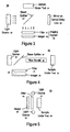
Figure 3 is a block diagram of an apparatus 30 for en-face imaging in an embodiment
in accordance with the invention. The imaging system 26 of apparatus 30 includes an imager
32 that is configured to collect image information at two (or more) wavelengths. In one
embodiment, a bulk or large area filter 31 is situated to intercept incident light before the light
reaches the imager 32. In an alternate embodiment, filter 31 is positioned to intercept light as
the light is emitted from light source 22. Although a single bulk filter is shown, the invention
is not so limited; for example, multiple bulk filters can be used in series. Imager 32 is
described further in conjunction with Figure 7, and filter 31 is described further in conjunction
with Figure 8.
-
In operation, apparatus 30 of Figure 3 functions as follows for an example based on
two wavelengths; however, the invention is not so limited. Light source 22 generates light
having a range of wavelengths including a first wavelength and a second wavelength. The first
and second wavelengths are selectable, as described above. The light may be filtered by an
optional bulk filter as it is transmitted from light source 22 (e.g., a bulk filter such as that
described by Figure 8). A portion of the light from light source 22 is directed to sample under
test 24 by beam splitter 27, and the remainder of the light is passed to mirror on optical delay
line 28. The light is essentially broadcast to the sample under test 24 and the mirror on optical
delay line 28.
-
Continuing with reference to Figure 3, light reflected from the sample under test 24 is
received by imager 32. The reflected light may be filtered by the optional filter 31 before the
light reaches imager 32. Imager 32 distinguishes between reflected light at the first
wavelength and reflected light at the second wavelength, as described further in conjunction
with Figure 7. Image data corresponding to the first wavelength and image data corresponding
to the second wavelength can be used to generate one or more en-face images. For example,
separate en-face images may be generated corresponding to the different wavelengths, or a
single en-face image may be generated based on the combination of the image data (for
example, as described below, image data may be differenced). Mirror on optical delay line 28
can then be used to increase the optical length of the reference arm (e.g., a mirror can be
moved to a different position), and the process is repeated to generate en-face images at
different depths of sample under test 24.
-
The discussion above describes an embodiment in which light travels in free space. As
mentioned previously herein, all or some of the free space portions of apparatus 30 can instead
be fiber-based. In one embodiment, with reference to Figures 2 and 3, light from beam splitter
27 is transmitted through fiber bundle 25 to the sample under test 24. Light reflected from
sample under test 24 is reflected back through fiber bundle 25, then to imager 32 via beam
splitter 27. Fiber bundle 25 can include one or more coherent optical fiber bundles. Light
from light source 22 can be passed through an optional lens before the light enters fiber bundle
25. A lens can be located between light source 22 and beam splitter 27 and/or between beam
splitter 27 and fiber bundle 25, and between fiber bundle 25 and sample under test 24.
-
Figure 4 is a block diagram of an apparatus 40 for en-face reflective imaging (not OCT)
in one embodiment in accordance with the invention. In operation, apparatus 40 functions as
follows for an example based on two wavelengths; however, the invention is not so limited.
Light source 22 generates light having multiple wavelengths including a first wavelength and a
second wavelength. The first and second wavelengths are selectable, as described above. The
light may be filtered by an optional bulk filter as it is transmitted from light source 22 (e.g., a
bulk filter such as that described by Figure 8). The light from light source 22 also may be
passed through an optional lens before reaching beam splitter 27 and/or before entering fiber
bundle 25.
-
The light is transmitted through fiber bundle 25 to the sample under test 24, where it is
reflected back through fiber bundle 25. Fiber bundle 25 can include one or more coherent
optical fiber bundles.
-
Light reflected from the sample under test 24 is directed to imager 32 via beam splitter
27. The reflected light may be passed through an optional lens before reaching imager 32.
The reflected light may be filtered by the optional filter 31 before the light reaches imager 32.
Imager 32 distinguishes between reflected light at the first wavelength and reflected light at the
second wavelength, as described further in conjunction with Figure 7. Image data
corresponding to the first wavelength and image data corresponding to the second wavelength
can be used to generate one or more en-face images. For example, separate en-face images
may be generated corresponding to the different wavelengths, or a single en-face image may be
generated based on the combination of the image data (for example, as described below, image
data may be differenced).
-
Figure 4 illustrates an application in which the light source 22 and imager 32 are
situated outside of the sample under test. Either or both the light source 22 and imager 32
could be situated within a body (e.g., on a tool such as an endoscope).
-
Figure 5 is a block diagram of an apparatus 50 for en-face reflective imaging (not OCT)
in one embodiment in accordance with the invention. In operation, apparatus 50 functions as
follows for an example based on two wavelengths; however, the invention is not so limited.
Light sources 52 generate light having multiple wavelengths including a first wavelength and a
second wavelength. Although light sources 52 is illustrated consisting of two light sources, the
invention is not so limited. The first and second wavelengths are selectable, as described
above. The light may be filtered by an optional bulk filter as it is transmitted from light
sources 52.
-
Light reflected from the sample under test 24 is reflected onto imager 32. The reflected
light may be filtered by the optional filter 31 before the light reaches imager 32. Imager 32
distinguishes between reflected light at the first wavelength and reflected light at the second
wavelength, as described further in conjunction with Figure 7. Image data corresponding to
the first wavelength and image data corresponding to the second wavelength can be used to
generate one or more en-face images. For example, separate en-face images may be generated
corresponding to the different wavelengths, or a single en-face image may be generated based
on the combination of the image data (for example, as described below, image data may be
differenced).
-
Figure 5 illustrates an application in which the light sources 52 and the imager 32 are
situated outside of the sample under test. Either or both the light sources 52 and the imager 32
could be situated within a body (e.g., on a tool such as an endoscope).
-
Figure 6 is a block diagram of an apparatus 60 for en-face transmissive imaging
through a sample under test 24 in one embodiment in accordance with the invention. In
operation, apparatus 60 functions as follows for an example based on two wavelengths;
however, the invention is not so limited. Light source 22 generates light having multiple
wavelengths including a first wavelength and a second wavelength. The first and second
wavelengths are selectable, as described above. The light may be filtered by an optional bulk
filter as it is transmitted from light source 22 (e.g., a bulk filter such as that described by
Figure 8). The light is essentially broadcast onto the sample under test 24.
-
The light is transmitted through the sample under test 24, where it is absorbed or
attenuated by an amount depending on the characteristics of the material through which the
light is passing. For example, the transmission of light at each wavelength is a function of the
thickness, composition and structure of the skin, tissue, bone, blood and other material through
which the light passes.
-
Continuing with reference to Figure 6, light from the sample under test 24 is received
by imager 32. The reflected light may be filtered by the optional filter 31 before the light
reaches imager 32. Imager 32 distinguishes between reflected light at the first wavelength and
reflected light at the second wavelength, as described further in conjunction with Figure 7.
Image data corresponding to the first wavelength and image data corresponding to the second
wavelength can be used to generate one or more en-face images. For example, separate en-face
images may be generated corresponding to the different wavelengths, or a single en-face
image may be generated based on the combination of the image data (for example, as
described below, image data may be differenced).
-
Figure 6 illustrates an application in which the light source 22 and imager 32 are
situated outside of the sample under test. Either or both the light source 22 and imager 32
could be situated within a body (e.g., on a tool such as an endoscope).
-
Figure 7 illustrates an imager 32 in one embodiment in accordance with the invention.
Figure 7 illustrates an example in which two wavelengths (λ1 and λ2) and two types of filters
are used. However, the invention is not so limited, and imager 32 can be configured for more
than two wavelengths and/or more than two types of filters. Imager 32 is illustrated as a five-by-five
array; however, the invention is not limited to those dimensions.
-
In the present embodiment, imager 32 includes a number of first regions and a number
of second regions. The first regions are for detecting light of the first wavelength (λ1) and the
second regions are for detecting light of the second wavelength (λ2). In one embodiment, the
first regions include a filter material for blocking (filtering) light of the second wavelength,
and the second regions include a filter material for blocking light of the first wavelength.
Using two different filters, one for each wavelength, facilitates the detection of the different
wavelengths; however, it is not necessary to use two different filters that perform as just
described. That is, in an alternate embodiment, the first regions include a filter material for
blocking (filtering) light of the second wavelength while detecting light of the first wavelength,
while the second regions detect light of both wavelengths (that is, the second regions do not
include a filter material for blocking light of the first wavelength).
-
In the embodiment of Figure 7, a checkerboard pattern is formed on the surface of
imager 32; however, other patterns of filter types/filter materials can be used. Patterns other
than checkerboard patterns can be used, for example, when more than two types of filters are
incorporated into imager 32. Patterns of filter types can be regular or irregular in nature. Also,
the different regions of imager 32 (corresponding to the different types of filters and filter
materials) are illustrated as being square in shape. However, the present invention is not so
limited; that is, regular-shaped regions other than squares as well as irregular-shaped regions
can be used. In one embodiment, each region corresponds to a respective pixel of the imager
32. For optical coherence tomography (OCT), pixel sensitivities and the excitation source are
selected so that the wavelengths λ1 and X2 are present in the spectrum of the light source.
-
Filters can be created as polymers doped with pigments or dyes, interference filters,
reflective filters, or absorbing filters made of semiconductors, metals, other inorganic
materials, or organic materials, created in any of a number of ways. Pigment-doped or dye-doped
polymer filters (e.g., colored photoresists) provide an inexpensive solution. Direct
deposition of organic pigments or dyes is also possible. Deposition of thin-film dielectric
filters is another approach, with proper design so that the dielectric filters are not too thick
compared to the lateral dimensions of the pixels. Deposition of semiconductor material with
distinct band-edge behavior provides yet another approach.
-
The filter materials can be deposited (e.g., layered) as a separate layer of imager 32
(e.g., on top of an underlying layer) using conventional deposition and photolithography
processes while still in wafer form, reducing the cost to manufacture. Additionally or
alternatively, the filter materials may be mounted as separate elements between the imager 32
and incident light, allowing filtering of light before the light reaches the surface of imager 32.
In yet another embodiment, the wavelength sensitivity may be varied within the silicon pixels
themselves in a checkerboard pattern, for example.
-
Image data collected at two wavelengths can be differenced to compare the responses at
the two wavelengths. An averaging technique can be applied before the wavelengths are
differenced. In general, a signal value for a region can be computed for a particular
wavelength using signal values from one or more neighboring regions at the same wavelength.
For example, an average signal value for λ2 can be determined for region 76 by averaging the
λ2 signal values for regions 72, 73, 74 and 75. The computed signal value for λ2 at region 76
can be compared to the measured signal value for λ1 at region 76.
-
Before processing (e.g., differencing) of the image data, gain factors can be applied to
the signals generated from the different regions or pixels of imager 32 to account for any
differences in sensitivity between the transmission characteristics of each region/pixel. Imager
32 can be used in combination with a bulk or large area filter (e.g., optional filter 31 of Figures
3-6), in which case the gain factors are determined considering the effect of filter 31 on the
region-by-region (pixel-by-pixel) differences in sensitivity of imager 32.
-
The processing of image data as just described can be carried out rapidly using an on-board
image processing chip, allowing rapid acquisition of successive en-face images. For
contemporary imagers at video graphics array (VGA) resolution, collection rates of 15 frames
per second are commonly achievable. Because adjacent regions (e.g., pixels) can be compared,
image distortions due to bulk optic effects (e.g., barrel distortion) are minimized. With use of
an averaging technique, signal values for the same region (e.g., pixel) can be compared, as
described above.
-
Consider the example mentioned above, in which two wavelengths are selected to
distinguish between oxyhemoglobin and hemoglobin without bound oxygen. Taking the
difference between signal values for the two wavelengths can facilitate discrimination between
regions of comparatively good and bad blood oxygenation. In other words, an en-face image
can be generated based on the difference between the two sets of image data. Alternatively, an
en-face image can be generated based on the set of image data corresponding to the first
wavelength, and another en-face image can be generated based on the set of image data
corresponding to the second wavelength.
-
Figure 8 illustrates transmission versus wavelength characteristics of filter 31 and
imager 32 (Figures 3-6) in accordance with the invention. As described in conjunction with
Figure 7 above, in the present embodiment, imager 32 includes a number of regions that block
a band of light that includes light at a first wavelength and a number of other regions that block
a band of light that includes light at a second wavelength. In the example of Figure 8, imager
32 includes regions that include photoresist filter 1 material to block the band of light that
includes light at the first wavelength (λ1), and regions that include photoresist filter 2 material
to block the band of light that includes light at the second wavelength (λ2).
-
Filter 31 includes one or more materials that serve to transmit light only within a
narrow wavelength band or bands. In the example of Figure 8, the filter 31 transmits light in
relatively narrow bands (peak 1 and peak 2) around the selected first and second wavelengths
(λ1 and λ2, respectively), blocking or reducing light of wavelengths outside the band. In other
words, only light in the relatively narrow bands around the first and second wavelengths passes
through filter 31 to imager 32. However, the bands are not so narrow as to degrade the depth
resolution. Accordingly, the detection of the first and second wavelengths by imager 32 is
facilitated.
-
Bulk interference filters commonly transmit integral subharmonics of the chosen
wavelength. For example, a filter designed to transmit 800 nm wavelength light will also
transmit 400 nm wavelength light. Order-sorting filters can be used as part of the filter 31 to
filter out light at wavelengths that are subharmonics of the first and second wavelengths. A
filter that blocks out light below 800 nm (e.g., a filter with a threshold of 600 nm) can be used
to block light at the subharmonic wavelengths.
-
Figure 9 is a block diagram of an apparatus 90 for en-face imaging in one embodiment
in accordance with the invention. Relative to apparatus 30 of Figure 3, for example, apparatus
90 includes a second beam splitter 99 and at least two imagers: first imager 93 and second
imager 96. The second beam splitter 99 can be a 50/50 beam splitter or a dichroic beam
splitter. The first imager 93 is for detecting light of a first wavelength, and the second imager
96 is for detecting light of a second wavelength.
-
Filters 91 and 95 are optionally included in apparatus 90. For example, if the second
beam splitter 99 is a dichroic beam splitter, then filters 91 and 95 may or may not be used. If
the second beam splitter 99 is a 50/50 beam splitter, then filter 91 can be used to block light of
the second wavelength from reaching the first imager 93, and filter 95 can be used to block
light of the first wavelength from reaching the second imager 96.
-
In operation, apparatus 90 of Figure 9 functions as follows for an example based on
two wavelengths; however, the invention is not so limited. Light source 92 generates light
having a first and second wavelength. The first and second wavelengths are selectable, as
described previously herein. The light transmitted by light source 92 may be filtered by an
optional bulk filter (e.g., a bulk filter such as that described by Figure 8). A bulk filter such as
that described by Figure 8 can optionally be placed in other locations within apparatus 90, for
example, before beam splitter 99.
-
Continuing with reference to Figure 9, a portion of the light from light source 92 is
directed to sample under test 94 by beam splitter 97, and the remainder of the light is passed to
mirror on optical delay line 98. The light is essentially broadcast to the sample under test 94
and the mirror on optical delay line 98 in free space, although some or all of the free space
portions of apparatus 90 can instead be fiber-based.
-
Light reflected from the sample under test 94 and from mirror on optical delay line 98
is received by beam splitter 99. If beam splitter 99 is a 50/50 beam splitter, half of the
reflected light from the sample is directed to the first imager 93 and the remainder of the
reflected light is directed to the second imager 96. Filter 91 can be used to block light of the
second wavelength from reaching the first imager 93, and filter 95 can be used to block light of
the first wavelength from reaching the second imager 96. If beam splitter 99 is a dichroic
beam splitter, then one wavelength (e.g., the second wavelength) would be reflected to second
imager 96 and other wavelength (e.g., the first wavelength) would be transmitted to first
imager 93.
-
First imager 93 detects light of the first wavelength, and second imager 96 detects light
of the second wavelength. Image data corresponding to the first wavelength and image data
corresponding to the second wavelength can then be used to generate one or more en-face
images. Image data generated by the two imagers can be differenced. As separate imagers, the
first imager 93 and the second imager 96 are registered spatially and synchronized temporally
to capture images at the different wavelengths simultaneously.
-
Figure 10 is a flowchart 100 of a method for en-face imaging using multiple
wavelengths in one embodiment in accordance with the invention. Although specific steps are
disclosed in flowchart 100, such steps are exemplary. That is, embodiments in accordance
with the invention are well suited to performing various other steps or variations of the steps
recited in flowchart 100. It is appreciated that the steps in flowchart 100 may be performed in
an order different than presented, and that not all of the steps in flowchart 100 may be
performed.
-
In step 102, en-face images are captured of a sample under test using light that has at
least a first and second wavelength. The wavelengths to be used for the en-face scanning and
imaging can be selected according to the application, the nature of the information that is being
collected, the nature of the subject under test, and other factors. The source of light can be a
broadband source, having wavelengths other than selected wavelengths. In one embodiment,
light transmitted from the light source is filtered to eliminate wavelengths outside the relatively
narrow band of the selected wavelengths.
-
In step 104, light reflected from the sample under test is received in an imaging system
that includes a single imager such as imager 32 of Figures 3-6, or multiple imagers such as
imagers 93 and 96 of Figure 9. The reflected light may be filtered before it reaches the
imagers.
-
In step 106 of Figure 10, reflected light corresponding to the first wavelength and
reflected light corresponding to the second wavelength are separated from each other. That is,
for example, an imager such as imager 32 (Figures 3-6) can have regions for detecting
reflected light at the first wavelength and other regions for detecting reflected light at the
second wavelength. Alternatively, a first imager (e.g., imager 93 of Figure 9) serves to detect
reflected light at the first wavelength and a second imager (e.g., imager 96 of Figure 9) serves
to detect light at the second wavelength.
-
In step 108 of Figure 10, en-face images are output based on the image data generated
by the imager or imagers. Separate en-face images can be output for each wavelength in use.
Alternatively, the image data for the different wavelengths can be differenced, and the
difference between the sets of image data can be used to generate an en-face image.
-
The process just described is repeated to obtain en-face images at different depths of
the sample under test.
-
In summary, embodiments in accordance with the invention allow the rapid collection
of en-face data by using a two-dimensional imager. Contrast is increased by providing the
capability for simultaneously imaging at multiple wavelengths. Using coherent fiber bundles,
in vivo as well as in vitro measurements can be performed.
-
The multiple wavelength en-face imagers described herein can be used in a variety of
applications, including medical imaging and measurement applications as part of OCT or
endoscopy. Medical imaging applications include coronary and vascular imaging, oncology,
dentistry, neurosurgery, gastroenterology, otolaryngology, dermatology, ophthalmology,
thoracic surgery, urology, and orthopedics. Measurement applications include cell imaging
and metrology in manufacturing.
-
Embodiments in accordance with the invention can be particularly advantageous when
fluorescent tags are being used. Conventionally, a patient is injected with a fluorescent
medium (e.g., a fluorescent dye) that will attach itself to cancerous cells, for example. Using
multiple (e.g., two) wavelengths and an en-face imaging system as described herein, it is not
necessary to take a "before" image, inject the dye and wait for the dye to take effect, and then
take an "after" image. Instead, the dye can be injected and, after the dye has taken effect,
simultaneous images can be taken using one wavelength that excites the dye fluorescence and
another wavelength that does not excite the fluorescence of that particular dye. Differencing of
the images can then be performed to highlight regions in the sample under test that fluoresced.
Conventionally, the patient may be subject to a degree of discomfort and perhaps a degree of
risk (e.g., if the patient is anesthetized) while waiting for the dye to take effect. Also during
that time, the imaging device or the patient may move slightly, causing the before and after
images to be offset. By taking simultaneous images in accordance with the invention, these
problems are overcome.
-
The invention is thus described in various embodiments. While the invention has been
described in particular embodiments, it should be appreciated that the invention should not be
construed as limited by such embodiments, but rather construed according to the following
claims.