EP1525902B1 - Delivery modification system for radiation therapy - Google Patents
Delivery modification system for radiation therapy Download PDFInfo
- Publication number
- EP1525902B1 EP1525902B1 EP20050001901 EP05001901A EP1525902B1 EP 1525902 B1 EP1525902 B1 EP 1525902B1 EP 20050001901 EP20050001901 EP 20050001901 EP 05001901 A EP05001901 A EP 05001901A EP 1525902 B1 EP1525902 B1 EP 1525902B1
- Authority
- EP
- European Patent Office
- Prior art keywords
- patient
- treatment
- sinogram
- radiation
- radiation therapy
- Prior art date
- Legal status (The legal status is an assumption and is not a legal conclusion. Google has not performed a legal analysis and makes no representation as to the accuracy of the status listed.)
- Expired - Lifetime
Links
Images


Classifications
-
- A—HUMAN NECESSITIES
- A61—MEDICAL OR VETERINARY SCIENCE; HYGIENE
- A61N—ELECTROTHERAPY; MAGNETOTHERAPY; RADIATION THERAPY; ULTRASOUND THERAPY
- A61N5/00—Radiation therapy
- A61N5/10—X-ray therapy; Gamma-ray therapy; Particle-irradiation therapy
-
- A—HUMAN NECESSITIES
- A61—MEDICAL OR VETERINARY SCIENCE; HYGIENE
- A61N—ELECTROTHERAPY; MAGNETOTHERAPY; RADIATION THERAPY; ULTRASOUND THERAPY
- A61N5/00—Radiation therapy
- A61N5/10—X-ray therapy; Gamma-ray therapy; Particle-irradiation therapy
- A61N5/1042—X-ray therapy; Gamma-ray therapy; Particle-irradiation therapy with spatial modulation of the radiation beam within the treatment head
-
- A—HUMAN NECESSITIES
- A61—MEDICAL OR VETERINARY SCIENCE; HYGIENE
- A61N—ELECTROTHERAPY; MAGNETOTHERAPY; RADIATION THERAPY; ULTRASOUND THERAPY
- A61N5/00—Radiation therapy
- A61N5/10—X-ray therapy; Gamma-ray therapy; Particle-irradiation therapy
- A61N5/1048—Monitoring, verifying, controlling systems and methods
- A61N5/1049—Monitoring, verifying, controlling systems and methods for verifying the position of the patient with respect to the radiation beam
-
- A—HUMAN NECESSITIES
- A61—MEDICAL OR VETERINARY SCIENCE; HYGIENE
- A61N—ELECTROTHERAPY; MAGNETOTHERAPY; RADIATION THERAPY; ULTRASOUND THERAPY
- A61N5/00—Radiation therapy
- A61N5/10—X-ray therapy; Gamma-ray therapy; Particle-irradiation therapy
- A61N5/103—Treatment planning systems
- A61N5/1037—Treatment planning systems taking into account the movement of the target, e.g. 4D-image based planning
-
- A—HUMAN NECESSITIES
- A61—MEDICAL OR VETERINARY SCIENCE; HYGIENE
- A61N—ELECTROTHERAPY; MAGNETOTHERAPY; RADIATION THERAPY; ULTRASOUND THERAPY
- A61N5/00—Radiation therapy
- A61N5/10—X-ray therapy; Gamma-ray therapy; Particle-irradiation therapy
- A61N5/1048—Monitoring, verifying, controlling systems and methods
- A61N5/1064—Monitoring, verifying, controlling systems and methods for adjusting radiation treatment in response to monitoring
- A61N5/1065—Beam adjustment
- A61N5/1067—Beam adjustment in real time, i.e. during treatment
Definitions
- This invention relates generally to radiation therapy equipment for the treatment of tumors or the like and specifically to a computerized method for rapidly correcting a radiation treatment plan to account for motion or change in shape of treatment areas.
- Radiotherapy treats tumorous tissues with high energy radiation.
- radiation may be x-ray radiation or accelerated electrons, protons, neutrons or heavy ions.
- the amount of radiation and its placement must be accurately controlled to ensure both that the tumor receives sufficient radiation to be destroyed and that the damage to the surrounding non-tumorous tissue is minimized.
- One highly accurate method of controlling the dose to a patient employs a radiation source that produces many individual rays whose intensity and/or energy may be independently controlled. This may be done by a series of shutters each controlling one ray or by a single modulated ray moved across the patient.
- the origin of the rays orbits the patient within a plane of the rays to illuminate a slice of the patient, when the orbit is planar, or several slices of the patient, when the orbit is helical.
- a mapping of the modulation of each beam as a function of angle forms a "treatment sinogram".
- the radiation treatment plan may be based on a computed tomography (CT) image of the patient.
- CT computed tomography
- a CT image is produced by a mathematical reconstruction of many projection images obtained at different angles about the patient.
- the origin of the fan beam orbits the patient within a plane of the fan to illuminate a slice of the patient, while the attenuation of each ray of the fan beam is measured as a function of that angle to obtain projections.
- the geometry of the CT acquisition is thus very similar to the geometry of the radiation therapy.
- Each CT projection forms a one-dimensional line image indicating the attenuation of the fan beam by a "slice" of the patient. Together these line images at each angle form an "attenuation sinogram" which may be reconstructed using well known algorithms such as filtered back projection into two dimensional tomographic images of the slice.
- the sinographic data which by itself is unintelligible, is normally no longer used or accessed by the user.
- the radiologist uses the CT image to determine the beam angles and intensities and/or energies (identified with respect to the tumor image) which will be used to treat the tumor.
- a computer program selects the beam angle and intensities and/or energies after the physician creates a dose map identifying the tumorous region and upper and lower dose limits for regions of the treatment.
- Preparing a treatment plan based on the dose map is a time consuming operation even on current high speed computers. Accordingly, the CT image of the patient is acquired before the time of radiation treatment. As a result, the patient will typically not be in the same position during the radiation treatment as the patient was during the CT imaging. The problem of properly aligning the patient is compounded when the treatment occurs in a number of different sessions over time.
- U.S. Patent 5,673,300 on which the pre-characterising portion of claim 1 is based describes a method of determining patient movement by obtaining a second CT image immediately prior to radiation therapy and comparing the sinogram of that CT image to the sinogram of the original CT image used for radiation treatment planning. This comparison yields an indication of patient movement which may be applied directly to the treatment sinogram used to control the radiation therapy machine.
- This invention by recognizing the close analogy between the attenuation sinograms of the CT image and of the treatment sinograms of radiation therapy treatment, greatly simplified detecting and correcting mis-registrations of the patient to the treatment sinogram.
- the present inventors have recognized that the above technique of directly modifying the treatment sinogram, by bypassing the time-consuming translation of dose map to treatment sinogram, makes possible real-time correction for patient motion. Such a correction may deduce real-time motion from a concurrent tomographic scan or from well known transducers used for measuring physiological motion. An improved method for correcting "fan beam" sinograms facilitates this use of the sinogram directly.
- the inventors have also recognized that the ability to manipulate sinograms to accommodate motion in the underlying structure, allows for a novel method of generating a treatment sinogram by combining precalculated partial sinograms representing treatments of standard elements of the patient. These standard elements may be moved to match a particular patient's anatomy and the partial sinograms modified according to the techniques described above. The partial sinograms are then combined and used directly or as a starting base for iterative treatment planning software.
- the present invention provides a method of operating a radiation therapy machine providing a radiation beam of individually intensity and/or energy modulated radiation rays separated along a radiation beam axis, the radiation beam axis positionable at a range of angles about a patient.
- a treatment sinogram is received providing intensities and/or energies of different rays for a given angle of the radiation beam, in a row, and intensities and/or energies of a given ray for different angles of the beam axis, in a column, for a patient at a first position.
- radiation treatment data indicating patient movement from the first position to a second position is also received and for each given beam axis angle of the treatment sinogram, the corresponding row of treatment sinogram is altered according to the indicated movement
- the movement may be detected by comparing a planning tomographic image of the patient contemporaneous with the preparation of the treatment sinogram to a monitoring tomographic image of the patient taken during radiation therapy.
- the patient movement may be determined by a model receiving as an input a physiological signal such as respiration or heart beat or external fiducial marks may be measured.
- the modification of the treatment sinogram may shift corresponding rows of treatment sinogram according to a component of patient motion perpendicular to the given beam axis.
- the modification of the treatment sinogram may scale corresponding rows of treatment sinogram according to a component of patient motion parallel to the given beam axis.
- the present invention also contemplates the preparation of a library of partial sinograms, each partial sinogram providing intensities and/or energies of different rays at given angles of the radiation beam axis, in sinogram rows, and intensity and/or energy of given rays for different angles of the beam axis, in sinogram columns, for a patient element in first modes.
- Sets of representations of patient elements may be arranged in combinations at second modes so as to model a given patient requiring radiation treatment. Changes in the patient elements between the first and second modes may be captured in alteration data. This alteration data may be used to modify the partial sinograms of each of the patient elements according to the alteration data and the partial sinograms may be combined to produce a treatment sinogram of the patient.
- alteration data may indicate either change in location or dimension of the patient elements, the latter which may be simple geometric shapes or may model specific organs.
- the treatment sinogram thus constructed may be further optimized to better conform with the dose map.
- a radiation therapy machine 10 suitable for use with the present invention, includes a radiotranslucent table 12 having a cantilevered top 14.
- the table top 14 is received within a bore 18 of an annular housing 20 of the radiation therapy machine 10 with movement of the table 12 along tracks 16 extending along a z-axis of a Cartesian coordinate system 22.
- Table 12 also includes an internal track assembly and elevator (not shown) to allow adjustment of the top 14 in a lateral horizontal position (indicated by the x-axis of the coordinate system 22) and vertically (indicated by the y-axis of the coordinate system 22). Motion in the x and y directions are limited by the diameter of the bore 18.
- the x-ray source 26 may be a conventional rotating anode x-ray tube, while the radiation source 28 may be any source of treatment radiation including one producing x-rays, accelerated electrons, protons or heavy ions such as are understood in the art.
- the x-ray source 26 and a radiation source 28 rotate with the gantry 24 about a center of rotation 64 near the top of patient table 12 when the table top 14 is positioned within the bore 18.
- the x-ray source 26 is collimated to produce a fan beam 30 lying generally within the x-y plane and crossing the bore 18 and thus the table top 14 when table top 14 is positioned within the bore 18.
- the fan beam 30 diverges about a central axis 31 whose angle is controlled by the position of the gantry 24.
- the axis 31 will henceforth be termed the projection axis.
- the fan beam 30 is received by a linear array detector 32 positioned diametrically across from the radiation source 28.
- the rotating gantry 24 permits fan beam radiographic projections of a patient on the table top 14 to be acquired at a variety of angles ⁇ about the patient.
- the radiation source 28 is mounted so as to project a fan beam of high energy radiation 34, similar to the fan beam 30, but crossing fan beam 30 at right angles so as to be received on the other side of the gantry 24 by radiation detector and stop 36.
- the stop is replaced by a detector to provide an alternative to the detector 32 for deducing motion of the patient.
- the fan beam of high energy radiation 34 diverges about a radiation axis centered within the beam and perpendicular to the projection axis 31.
- the radiation source 28 has a collimator 38 mounted in front of it to divide the beam of high energy radiation 34 into multiple adjacent rays whose energy and/or fluence may be individually controlled.
- control of the energy and/or fluence of the rays should be understood to include not only the energy of individual x-ray photons (or particles in the case of radiation therapy using electrons, protons or heavy ions) but alternatively or in addition the total number of photons or particles such as is a function of fluence, fluence rate and exposure time.
- the energy of the particles, fluence and fluence rate may be controlled using sinograms which may be modified by the present invention as will be apparent from the following description.
- a collimator suitable for fluence control type is described in U.S. Patent 5,317,616 assigned to the assignee of the present case a simple modification of this collimator using wedge filters may be used for particle energy control.
- a scanning single beam system may be used or other system providing a set of individually modulated rays.
- the location of the radiation source 28 and x-ray source 26 are precisely characterized so that images obtained from the x-ray source 26 may be used to aim the radiation source 28.
- a computer 40 having a display screen 42 and user entry mouse and keyboard 44 well known in the art is connected to the radiation therapy machine 10 to control motion of the table 12 and to coordinate operation of the gantry 24 together with the radiation source 28 and x-ray source 26 and to collect data from the linear array detector 32 during a scan of the patient according to methods well known in the art.
- a slice 50 of the patient taken along the x-y plane includes two zones 54 within a larger zone 52.
- Radiation passing along beam axis 31 through the slice 50 produces a projection 56 which records the attenuation of x-rays passing through to slice 50 along a single line perpendicular to the beam axis 31 (for CT) or provides a radiation treatment projection of different e energy and/or intensity of beams corresponding to the different zones 52 and 54 (for radiotherapy).
- the distance along this perpendicular to the projection axis is designated: t .
- the zones 54 may be resolved separately at the vertical angle and hence two peaks 58 (attenuation or radiation energy and/or intensity) are present in the projection 56.
- projections at a different angle ⁇ over 360 degrees may be combined to form an sinogram 60 which is stored temporarily in computer 40 as a matrix of data. As depicted, this matrix of data is arranged with each row representing a different angle ⁇ and each column a different distance t along the projection.
- each element of the matrix is a value of attenuation.
- each element of the matrix is an energy and/or fluence of a ray of the treatment beam.
- the values may be stored as numeric variables in the computer 40 and are shown as shaded curves 62.
- the pattern of the sinogram 60 is generally that of superimposed sinusoidal curves 62 (hence the name) each curve 62 having a fundamental period in ⁇ of 360 degrees as a result of the apparent movement of zones 54 in orbit about a center of gantry rotation 64 as projections are taken at various angles ⁇ .
- zones 54 toward the axis of rotation 64 of the gantry trace smaller amplitude sine curves whereas zones 54 further from the center of rotation 64 trace greater amplitude sine curves.
- an attenuation sinogram may be reconstructed into a tomographic image of the slice 50.
- an attenuation sinogram having t values spanning the largest cross-sectional width of an imaged slice 50 and ⁇ values over 360 degrees is sufficient to reconstruct a tomographic image of the slice through, for example, the method of filtered back projection.
- a treatment sinogram may be used to control the e energy and/or fluence of adjacent rays of a fan beam of high energy radiation 34 transmitted through the patient.
- a radiation treatment plan might well conform generally to curves 62 which would produce beams of high intensity radiation that would intersect at the zones 54 at a variety of different angles ⁇ to produce a high cumulative dose at the zones 54 but low dose elsewhere.
- the tomographic image produced from the sinogram 60 may be employed to establish a radiation treatment plan precisely related to that tomographic image.
- U.S. Patent 5,661,773 describes generally an interactive method for generating a treatment plan in the form of a sinogram 60 based on a tomographic image.
- the imaged object 51 is divided into a plurality of slices 70 separated along the z-axis and the acquisition of projections or the radiation treatment is obtained with the beam axis 31 constrained to a single plane as it rotates about the imaged object 51 indicated generally by arrow 72.
- the object is moved along the z-axis by movement of the table 12 until the next slice is aligned with the beam axis 31.
- the projection axis follows a helical path through the imaged object 51 in which the table 12 is incremented by a small amount in z with each change in angle ⁇ .
- a series of sinograms 60' is used (attenuation and treatment), each one identical to that described with respect to Fig. 3 and typically encompassing 360 degrees of gantry motion.
- Different slices 70 produce different ones of a sequence of sinogram 60' each of which has a different but constant z value.
- the helical acquisition produces a sinogram 60" in which each row of the sinogram 60" represents a different increment in both ⁇ and in Z.
- a zone 54 extends only through the first two slices 70.
- the first two sinograms 60' show sine curves 62 related to the zone 54.
- the first 720 degrees of the sinogram 60" show a sign curve 62.
- the radiation therapy machine 10 or an independent CT machine may be used to acquire tomographic data in the form of an attenuation sinogram 41 of a patient 43.
- the attenuation sinogram 41 generally provides rows (here depicted vertically) comprising a set of attenuation measurements A(t) received by the detector 32 at different rays at a given projection angle ⁇ and columns (here depicted horizontally) representing the same data for different projection angles ⁇ .
- the attenuation sinogram 41 is received by a tomographic reconstructor 45 such as one using well known filtered backprojection algorithms. to provide a planning tomographic image 46 depicting a slice of the patient 43. This and the following steps may be performed on computer 40.
- the planning tomographic image 46 may be provided to a dose map editor 48 where it provides a background on which a dose map 55 is prepared by a physician.
- the dose map 55 depicts the desired dose in regions within the slice of the patient 43.
- the dose map 55 is prepared interactively with editing commands 53 from a keyboard or cursor control device being received by the dose map editor 48.
- the dose map 55 is used to prepare a treatment sinogram 57 describing energy and/or fluence of plurality of radiation beams from the radiation source 28 at different beam angles ⁇ that will produce the desired dose of the dose map 55.
- the treatment sinogram 57 is generally arranged with rows (here depicted vertically) providing values of a function I(t) indicating beam energy and/or fluence for different rays t within a beam and columns (here depicted horizontally) providing values of a function I( ⁇ ) indicating beam energy and/or fluence for different beam angles ⁇ .
- the process of converting the dose map 55 to the treatment sinogram is performed as an iterative optimization by planning software 59.
- the planning software 59 produces a trial sinogram 101 which is provided to a dose calculator 61, the latter which determines the dose that would be produced by the trial sinogram and comparing it to the desired dose as indicated by comparison node 102.
- the planning software 59 receiving an indication of the deviation between the dose provided by the trial sinogram 101 and the dose map 55 then modifies the beam energy and/or fluence of the trial sinogram 101 according to that deviation and the process is repeated until a treatment sinogram 57 is obtained.
- the treatment sinogram 57 is then provided to control the collimator 38 for treatment of the patient 43.
- an arbitrary motion of an object from position 63 to position 63' by ⁇ ⁇ r ⁇ provides not only a shifting of the sinogram rows I(t) but can provide a magnification of that function.
- the object at position 63' moving closer to the origin of the fan beam as well as across the origin of the fan beam causes a shifting of the function I( t + ⁇ ) and a scaling of the function I( ⁇ t ) reflecting the relative magnification effects caused by moving toward and away from the origin of the fan beam of high energy radiation 34.
- the amounts ⁇ and ⁇ depend on the particular dimensions of the radiation therapy machine 10 and will generally be functions of the amount of motion and the origin of the motion and may be determined by well understood geometric techniques. Generally the scaling and shifting need not be linear functions and need not be uniform over the patient.
- Correction of the treatment sinogram may be provided in a number of ways.
- the rows and columns of the treatment sinogram are rebinned to reflect a sinogram providing an identical radiation pattern but on a machine having parallel rays.
- This rebinning process is a geometric transformation well understood in the computed tomography art and may be calculated on-the-ffy using mathematical formulas or by precalculated to produce a table mapping elements of the fan beam treatment sinogram 57 to corresponding elements of a parallel ray sinogram. Generally, an interpolation step will be required so that the elements map to the integer ray and beam angle values of the sinogram.
- This rebinning is indicated by process block 81.
- the component of the motion perpendicular to the beam angle is determined and used to shift the particular row of the sinogram in direct proportion to that component.
- Motion parallel to the beam angle may be disregarded as a result of the parallel ray geometry.
- the resultant shifted parallel ray sinogram may be rebinned to a divergent ray sinogram using the inverse process described with process block 81.
- the resultant sinogram will have been corrected both for parallel and perpendicular motion of the patient.
- a perpendicular component ⁇ ⁇ r ⁇ ⁇ of motion ⁇ ⁇ r ⁇ may be determined as indicated by process block 86. Then at process block 88, the rows may be shifted proportionally to this component and the magnification caused by the diverging rays of the fan beam.
- the parallel component of the motion ⁇ r l with respect to a beam axis at ⁇ may be determined and at process block 92, the rows may be scaled appropriately.
- the scaled and shifted rows may be resampled to fit within the integer values allowed in the treatment sinogram 57.
- the corrected sinogram I( ⁇ t+ ⁇ ) will have discontinuities that do not lie on the separation between the leaves of the collimator 38 which define the rays. For this reason, the sinogram will have to be resampled to fit within the confines of the treatment sinogram 57. Standard methods of interpolation can be used for this resampling. The inventors recognize that there are additional errors in this approach including the failure to account for scatter but it is believed that these errors are small or can be corrected for.
- the above described treatment sinogram modification technique or the more simple treatment sinogram modification described in predecessor parent 5,673,300 may be used to provide for real-time motion correction.
- a regular tomographic projection signal may be obtained using detector 32 or a megavoltage tomographic projection signal may be obtained by using a megavoltage detector 65.
- the images thus obtained may be used to provide a real-time imaging sinogram 67 which may be compared to the planning attenuation sinogram 41 as indicated by comparison block 83 according to the techniques described in the above mentioned patent to provide a motion signal 69.
- the comparison between the two attenuation sinograms 41 and 67 correlates rows of the sinograms at particular beam angles to determine patient motion in one or more orthogonal axes. More generally, this technique may be expanded to completely define the motion of the patient 43 in six parameters of x, y and z and roll, yaw and pitch.
- a patient motion sensor 66 may be used to provide a physiological signal from the patient indicating motion.
- the sensor 66 in its simplest case may be a pressure cuff to detect chest wall expansion commensurate with breathing or may simply detect an electronic signal such as an ECG signal.
- the thus detected signal 71 may be provided to a mathematical model 73 relating the cycle of the signal to internal changes in the patient either through the use of a simple mathematical modeling of the patient, for example, breathing as an expansion of a generally oval chest wall, or by keying different phases of the cycle of the signal to measured tomographic images of the patient or of a standard patient that would indicate changes in location or aspect of internal structures of the patient 43.
- the patient motion sensor may alternatively be optical, using external fiducial marks optically detected by lasers or the like, or may employ signals from other known imaging systems such as magnetic resonance imaging (MRI) or may be provided by positioning fixtures attached to the patient employing well know location/orientation determining technologies such as those using radio or light transmitters and receivers as are known for virtual reality headsets and the like.
- MRI magnetic resonance imaging
- These signals 69 from either source may be provided to a sinogram manipulation program 74 implemented as software in a high speed computer processor performing the transformations described above, the inputs describing the ⁇ ⁇ ⁇ r ⁇ ⁇ ⁇ r value and absolute coordinate information.
- the sinogram manipulation program 74 thus receives a sinogram as prepared above as described in Fig. 7 to produce a modified treatment sinogram 76 which may be provided to the collimator 38 on a real-time basis so as to modify the actual radiation treatment on a real-time basis.
- the ability to modify the treatment sinogram 57 through simple mathematical operations such as shifting and scaling provides the ability to make the rapid corrections required of real-time. Further in the case where a model 73 is used, modifications may be anticipated and calculated in advance, and/or multiple modified treatment sinograms 76 may be precalculated and simply switched into communication with the collimator 38 as required.
- the correction process applied to the sinogram need not only deal with displacement of objects, either within the patient or including the entire patient, but may accommodate general dimensional changes of objects within the patient to a limited degree.
- object in mode 63 may inflate to become object in mode 63" to the predictable effect of expanding by scaling the sinogram function I(t) necessary to continue to treat that structure.
- a similar expansion in this case is found in all beam angles.
- complex organ dimensional changes may be accommodated through this technique without the need for recalculation of the dose map 55.
- such a system prepares a series of partial sinograms 80(a) through 80(c) each corresponding to a predetermined patient element 82(a) through 82(c) and providing a standard treatment for those elements.
- These partial sinograms 80(a) through 80(c) may be prepared using conventional planning software and optimized over the course of an arbitrarily long period of time and then stored for later use in an electronically accessible library together with representations of patient elements 82(a) through 82(c) indicating an area, possibly an expected material, and a desired treatment dose.
- the dose map editor 48 receives representations corresponding to the treatment zones and doses of patient elements 82(a) through 82(c) and allows them to be manipulated with respect to the planning tomographic image 46 both by translation with respect to the planning tomographic image 46 and by expansion and contraction. These manipulation commands are received as editing commands 53 and are also provided via line 85 to the sinogram manipulation program 74.
- the sinogram manipulation program 74 modifies the partial sinograms 80(a) through 80(c) as has been described above to conform to the new spatial locations and dimensions of their associated patient elements 82.
- the sinograms 80(a) through 80(c) for the selected patient elements 82(a) through 82(c) used in the creation of a dose map 55 may then be summed or otherwise combined to produce the treatment sinogram 76.
- the combination operates on element pairs of corresponding rows and columns.
- a physician wishing to treat a tumorous organ might select a patient element 82(a) representing a preplanned treatment for that organ based on some average person and combine it with a second patient element 82(a) representing a nearby sensitive structure where radiation is to be avoided.
- These two portions may be placed upon a representation of the patient's torso also modeled by a portion as aligned against a tomographic image of an actual patient.
- the resulting treatment sinogram 76 may be provided directly to the collimator 38 or may be used as a starting point for further optimizations using the iteration of the dose calculator 61 and the planning software 59 as has been described before.
- the patient elements may thus represent either standard organs or standard geometric shapes of predetermined density and a desired dose. To the extent that many patient's treatments will be similar, except for minor anatomical dimensional variations, such a system allows the physician to use proven radiation therapy techniques across patients.
- the technique of preparing a treatment sinogram from partial sinograms 80 may be further augmented by the motion detection provided by signals 69 to the extent that motion identified to a particular organ may be identified to a single, partial sinogram 80 and thus distinguishable from the other components of the treatment sinogram 57 allowing adjustment of that organ in isolation.
Abstract
Description
- This invention relates generally to radiation therapy equipment for the treatment of tumors or the like and specifically to a computerized method for rapidly correcting a radiation treatment plan to account for motion or change in shape of treatment areas.
- Medical equipment for radiation therapy treats tumorous tissues with high energy radiation. Such radiation may be x-ray radiation or accelerated electrons, protons, neutrons or heavy ions. The amount of radiation and its placement must be accurately controlled to ensure both that the tumor receives sufficient radiation to be destroyed and that the damage to the surrounding non-tumorous tissue is minimized.
- One highly accurate method of controlling the dose to a patient employs a radiation source that produces many individual rays whose intensity and/or energy may be independently controlled. This may be done by a series of shutters each controlling one ray or by a single modulated ray moved across the patient. The origin of the rays orbits the patient within a plane of the rays to illuminate a slice of the patient, when the orbit is planar, or several slices of the patient, when the orbit is helical. By properly selecting the ray intensities and/or energies at different angles, complex regions within the slice may be accurately irradiated. A mapping of the modulation of each beam as a function of angle forms a "treatment sinogram".
-
U.S. Patent 5,317,616 issued May 31, 1994 such machine and a method of calculating the necessary beam intensities and/or energies as a function of angle. - In order to take advantage of the improved accuracy in dose placement offered by such radiation therapy systems, the radiation treatment plan may be based on a computed tomography (CT) image of the patient. As is known in the art, a CT image is produced by a mathematical reconstruction of many projection images obtained at different angles about the patient. In a typical fan beam CT acquisition, the origin of the fan beam orbits the patient within a plane of the fan to illuminate a slice of the patient, while the attenuation of each ray of the fan beam is measured as a function of that angle to obtain projections. The geometry of the CT acquisition is thus very similar to the geometry of the radiation therapy.
- Each CT projection forms a one-dimensional line image indicating the attenuation of the fan beam by a "slice" of the patient. Together these line images at each angle form an "attenuation sinogram" which may be reconstructed using well known algorithms such as filtered back projection into two dimensional tomographic images of the slice. The sinographic data, which by itself is unintelligible, is normally no longer used or accessed by the user.
- Using the CT image, the radiologist views the tumorous area and determines the beam angles and intensities and/or energies (identified with respect to the tumor image) which will be used to treat the tumor. In an automated system, a computer program selects the beam angle and intensities and/or energies after the physician creates a dose map identifying the tumorous region and upper and lower dose limits for regions of the treatment.
- Preparing a treatment plan based on the dose map is a time consuming operation even on current high speed computers. Accordingly, the CT image of the patient is acquired before the time of radiation treatment. As a result, the patient will typically not be in the same position during the radiation treatment as the patient was during the CT imaging. The problem of properly aligning the patient is compounded when the treatment occurs in a number of different sessions over time.
-
U.S. Patent 5,673,300 on which the pre-characterising portion ofclaim 1 is based describes a method of determining patient movement by obtaining a second CT image immediately prior to radiation therapy and comparing the sinogram of that CT image to the sinogram of the original CT image used for radiation treatment planning. This comparison yields an indication of patient movement which may be applied directly to the treatment sinogram used to control the radiation therapy machine. This invention, by recognizing the close analogy between the attenuation sinograms of the CT image and of the treatment sinograms of radiation therapy treatment, greatly simplified detecting and correcting mis-registrations of the patient to the treatment sinogram. - The present inventors have recognized that the above technique of directly modifying the treatment sinogram, by bypassing the time-consuming translation of dose map to treatment sinogram, makes possible real-time correction for patient motion. Such a correction may deduce real-time motion from a concurrent tomographic scan or from well known transducers used for measuring physiological motion. An improved method for correcting "fan beam" sinograms facilitates this use of the sinogram directly.
- The inventors have also recognized that the ability to manipulate sinograms to accommodate motion in the underlying structure, allows for a novel method of generating a treatment sinogram by combining precalculated partial sinograms representing treatments of standard elements of the patient. These standard elements may be moved to match a particular patient's anatomy and the partial sinograms modified according to the techniques described above. The partial sinograms are then combined and used directly or as a starting base for iterative treatment planning software.
- Specifically, then, the present invention provides a method of operating a radiation therapy machine providing a radiation beam of individually intensity and/or energy modulated radiation rays separated along a radiation beam axis, the radiation beam axis positionable at a range of angles about a patient. A treatment sinogram is received providing intensities and/or energies of different rays for a given angle of the radiation beam, in a row, and intensities and/or energies of a given ray for different angles of the beam axis, in a column, for a patient at a first position. During radiation treatment data indicating patient movement from the first position to a second position is also received and for each given beam axis angle of the treatment sinogram, the corresponding row of treatment sinogram is altered according to the indicated movement
- Thus it is one object of the invention to make possible real-time correction of patient motion to correct not only patient positioning errors but physiological motions such as caused by respiration and cardiac motion. Direct operation on the treatment sinogram renders such real-time control possible.
- The movement may be detected by comparing a planning tomographic image of the patient contemporaneous with the preparation of the treatment sinogram to a monitoring tomographic image of the patient taken during radiation therapy. Alternatively, the patient movement may be determined by a model receiving as an input a physiological signal such as respiration or heart beat or external fiducial marks may be measured.
- Thus it is another object of the invention to provide a method of detecting patient motion on a real-time basis in a radiation therapy setting.
- The modification of the treatment sinogram may shift corresponding rows of treatment sinogram according to a component of patient motion perpendicular to the given beam axis.
- Thus, it is another object of the invention to provide an extremely simple operation on the treatment sinogram such as may be performed in real-time.
- The modification of the treatment sinogram may scale corresponding rows of treatment sinogram according to a component of patient motion parallel to the given beam axis.
- Thus it is another object of the invention to provide a more sophisticated modification of the treatment sinogram addressing the geometry of the highly efficient fan beam radiation therapy machine.
- The present invention also contemplates the preparation of a library of partial sinograms, each partial sinogram providing intensities and/or energies of different rays at given angles of the radiation beam axis, in sinogram rows, and intensity and/or energy of given rays for different angles of the beam axis, in sinogram columns, for a patient element in first modes. Sets of representations of patient elements may be arranged in combinations at second modes so as to model a given patient requiring radiation treatment. Changes in the patient elements between the first and second modes may be captured in alteration data. This alteration data may be used to modify the partial sinograms of each of the patient elements according to the alteration data and the partial sinograms may be combined to produce a treatment sinogram of the patient.
- Thus it is another object of the invention to make use of the ability to directly modify treatment sinograms to prepare template sinograms that may be simply combined to produce a treatment sinogram without the need for extensive treatment planning operations. The alteration data may indicate either change in location or dimension of the patient elements, the latter which may be simple geometric shapes or may model specific organs.
- Thus it is another object of the invention to provide in a finite library of patient elements sufficient to permit assembly of an approximate treatment sinogram.
- The treatment sinogram thus constructed may be further optimized to better conform with the dose map.
- Thus it is another object of the invention to provide an advanced starting point for dose optimization such as may reduce the number of iterations and thus the time required to prepare the treatment sinogram.
- The foregoing and other objects and advantages of the invention will appear from the following description. In the description, reference is made to the accompanying drawings which form a part hereof and in which there is shown by way of illustration a preferred embodiment of the invention. Such embodiment does not necessary represent the full scope of the invention, however, and reference must be made to the claims herein for interpreting the scope of the invention.
-
Fig. 1 is a perspective, cut-away view of a radiation therapy system providing for the acquisition of radiographic projections and for the generation of high energy radiation therapy beams and showing a patient table for supporting a patient thereon; -
Fig. 2 is a simplified view of a slice of an object, such as a patient, showing line projections of the object taken at two angles θ, with attenuations A along dimension t indicated in the vertical axis of each projection; -
Fig. 3 is a sinogram formed of multiple line projections such as those acquired inFig. 2 , over 360 degrees of angle θ with the attenuation of the projections indicated by shading; -
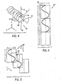
Fig. 4 is a perspective view of a simplified object that may be scanned showing a helical and slice-by-slice scanning path; -
Fig. 5 is a set of sinograms of the object ofFig. 4 such as may be obtained in a slice-by-slice scanning; -
Fig. 6 is a sinogram of the object ofFig. 4 such as may be obtained in a helical scan; -
Fig 7 is combination block diagram and flow chart showing the steps of preparing a treatment sinogram used for controlling a radiation therapy machine, from a computed tomography scan taken on the same or a different machine; -
Figs. 8a and 8b are figures similar toFig. 2 showing the effect of movement of a structure in a parallel beam and fan beam system, respectively; -
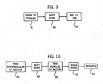
Fig. 9 is a flow chart showing the steps of a first method of correcting for motion within a fan beam involving rebinning the fan sinogram to a parallel configuration; -
Fig. 10 is a flow chart similar to that ofFig. 9 showing a second method of correcting for motion within a fan beam involving direct mathematical manipulation by scaling and shifting of the treatment sinogram without rebinning to parallel beam configuration; -
Fig. 11 is a figure similar to that ofFigs. 2 ,8a and 8b showing the effect of in-place expansion of an object in contrast to translative movement ofFigs. 8a and 8b ; and -
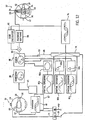
Fig. 12 is a figure similar to that ofFig. 7 showing elements of the real-time motion correction employed by the present invention and the construction of a treatment sinogram from precalculated partial sinograms. - Referring now to
Fig. 1 , aradiation therapy machine 10, suitable for use with the present invention, includes a radiotranslucent table 12 having acantilevered top 14. Thetable top 14 is received within abore 18 of anannular housing 20 of theradiation therapy machine 10 with movement of the table 12 alongtracks 16 extending along a z-axis of a Cartesian coordinatesystem 22. - Table 12 also includes an internal track assembly and elevator (not shown) to allow adjustment of the top 14 in a lateral horizontal position (indicated by the x-axis of the coordinate system 22) and vertically (indicated by the y-axis of the coordinate system 22). Motion in the x and y directions are limited by the diameter of the
bore 18. - A rotating
gantry 24, coaxial with thebore 18 and positioned. within thehousing 20, supports anx-ray source 26 and a highenergy radiation source 28 on its inner surface. Thex-ray source 26 may be a conventional rotating anode x-ray tube, while theradiation source 28 may be any source of treatment radiation including one producing x-rays, accelerated electrons, protons or heavy ions such as are understood in the art. Thex-ray source 26 and aradiation source 28 rotate with thegantry 24 about a center ofrotation 64 near the top of patient table 12 when thetable top 14 is positioned within thebore 18. - The
x-ray source 26 is collimated to produce afan beam 30 lying generally within the x-y plane and crossing thebore 18 and thus thetable top 14 whentable top 14 is positioned within thebore 18. Thefan beam 30 diverges about acentral axis 31 whose angle is controlled by the position of thegantry 24. Theaxis 31 will henceforth be termed the projection axis. - After exiting the
table top 14, thefan beam 30 is received by alinear array detector 32 positioned diametrically across from theradiation source 28. Thus, the rotatinggantry 24 permits fan beam radiographic projections of a patient on thetable top 14 to be acquired at a variety of angles θ about the patient. - The
radiation source 28 is mounted so as to project a fan beam ofhigh energy radiation 34, similar to thefan beam 30, but crossingfan beam 30 at right angles so as to be received on the other side of thegantry 24 by radiation detector and stop 36. In an alternative embodiment, the stop is replaced by a detector to provide an alternative to thedetector 32 for deducing motion of the patient. The fan beam ofhigh energy radiation 34 diverges about a radiation axis centered within the beam and perpendicular to theprojection axis 31. - The
radiation source 28 has acollimator 38 mounted in front of it to divide the beam ofhigh energy radiation 34 into multiple adjacent rays whose energy and/or fluence may be individually controlled. As used herein, control of the energy and/or fluence of the rays should be understood to include not only the energy of individual x-ray photons (or particles in the case of radiation therapy using electrons, protons or heavy ions) but alternatively or in addition the total number of photons or particles such as is a function of fluence, fluence rate and exposure time. In the case of radiotherapy using particles, the energy of the particles, fluence and fluence rate may be controlled using sinograms which may be modified by the present invention as will be apparent from the following description. - A collimator suitable for fluence control type is described in
U.S. Patent 5,317,616 assigned to the assignee of the present case
a simple modification of this collimator using wedge filters may be used for particle energy control. Alternatively, a scanning single beam system may be used or other system providing a set of individually modulated rays. The location of theradiation source 28 andx-ray source 26 are precisely characterized so that images obtained from thex-ray source 26 may be used to aim theradiation source 28. - A
computer 40 having adisplay screen 42 and user entry mouse andkeyboard 44 well known in the art is connected to theradiation therapy machine 10 to control motion of the table 12 and to coordinate operation of thegantry 24 together with theradiation source 28 andx-ray source 26 and to collect data from thelinear array detector 32 during a scan of the patient according to methods well known in the art. - Referring now to
Fig. 2 , aslice 50 of the patient taken along the x-y plane includes twozones 54 within alarger zone 52. Radiation passing alongbeam axis 31 through the slice 50 (at a vertical or anterior/posterior angle ("AP")) produces aprojection 56 which records the attenuation of x-rays passing through to slice 50 along a single line perpendicular to the beam axis 31 (for CT) or provides a radiation treatment projection of different e energy and/or intensity of beams corresponding to thedifferent zones 52 and 54 (for radiotherapy). In either case, the distance along this perpendicular to the projection axis is designated: t. Thezones 54 may be resolved separately at the vertical angle and hence two peaks 58 (attenuation or radiation energy and/or intensity) are present in theprojection 56. - In contrast at a second projection along a projection axis 31' at an angle θ from vertical, the
zones 54 are aligned so that the projection 56' shows a single peak 58'; - Referring now to
Fig. 3 , projections at a different angle θ over 360 degrees, may be combined to form ansinogram 60 which is stored temporarily incomputer 40 as a matrix of data. As depicted, this matrix of data is arranged with each row representing a different angle θ and each column a different distance t along the projection. For a CT attenuation sinogram, each element of the matrix is a value of attenuation. For a radiation treatment sinogram, each element of the matrix is an energy and/or fluence of a ray of the treatment beam. The values may be stored as numeric variables in thecomputer 40 and are shown as shaded curves 62. - The pattern of the
sinogram 60 is generally that of superimposed sinusoidal curves 62 (hence the name) eachcurve 62 having a fundamental period in θ of 360 degrees as a result of the apparent movement ofzones 54 in orbit about a center ofgantry rotation 64 as projections are taken at various angles θ. Generally,zones 54 toward the axis ofrotation 64 of the gantry trace smaller amplitude sine curves whereaszones 54 further from the center ofrotation 64 trace greater amplitude sine curves. The phase of the sine curves depends generally on the initial position of thezones 54 with respect to the first projection at θ = 0. - In a conventional CT acquisition, an attenuation sinogram may be reconstructed into a tomographic image of the
slice 50. As is well understood in the art, an attenuation sinogram having t values spanning the largest cross-sectional width of an imagedslice 50 and θ values over 360 degrees is sufficient to reconstruct a tomographic image of the slice through, for example, the method of filtered back projection. - In radiation therapy, a treatment sinogram may be used to control the e energy and/or fluence of adjacent rays of a fan beam of
high energy radiation 34 transmitted through the patient. For example, if thezones 54 ofFig. 2 were tumors, a radiation treatment plan might well conform generally tocurves 62 which would produce beams of high intensity radiation that would intersect at thezones 54 at a variety of different angles θ to produce a high cumulative dose at thezones 54 but low dose elsewhere. - Referring again to
Fig. 1 , it follows that the tomographic image produced from thesinogram 60 may be employed to establish a radiation treatment plan precisely related to that tomographic image.U.S. Patent 5,661,773 describes generally an interactive method for generating a treatment plan in the form of asinogram 60 based on a tomographic image. - Referring now to
Fig. 4 , in a "slice-by-slice" tomographic acquisition or in a slice-by-slice radiation treatment, the imagedobject 51 is divided into a plurality ofslices 70 separated along the z-axis and the acquisition of projections or the radiation treatment is obtained with thebeam axis 31 constrained to a single plane as it rotates about the imagedobject 51 indicated generally byarrow 72. At the conclusion of 360 degrees of rotation the object is moved along the z-axis by movement of the table 12 until the next slice is aligned with thebeam axis 31. - In an alternative acquisition or treatment method termed "helical scanning", the projection axis follows a helical path through the imaged
object 51 in which the table 12 is incremented by a small amount in z with each change in angle θ. - In the former slice-by-slice method, a series of sinograms 60' is used (attenuation and treatment), each one identical to that described with respect to
Fig. 3 and typically encompassing 360 degrees of gantry motion.Different slices 70 produce different ones of a sequence of sinogram 60' each of which has a different but constant z value. - In contrast, the helical acquisition produces a
sinogram 60" in which each row of thesinogram 60" represents a different increment in both θ and in Z. - In the example shown in
Fig. 4 , azone 54 extends only through the first twoslices 70. Hence, inFig. 5 , only the first two sinograms 60' show sine curves 62 related to thezone 54. Likewise, in the helically acquiredsinogram 60" ofFig. 6 only the first 720 degrees of thesinogram 60" show asign curve 62. - Referring now to
Fig. 7 , theradiation therapy machine 10 or an independent CT machine (not shown) may be used to acquire tomographic data in the form of anattenuation sinogram 41 of apatient 43. As described above, theattenuation sinogram 41 generally provides rows (here depicted vertically) comprising a set of attenuation measurements A(t) received by thedetector 32 at different rays at a given projection angle θ and columns (here depicted horizontally) representing the same data for different projection angles θ. - The
attenuation sinogram 41 is received by atomographic reconstructor 45 such as one using well known filtered backprojection algorithms. to provide aplanning tomographic image 46 depicting a slice of thepatient 43. This and the following steps may be performed oncomputer 40. - The
planning tomographic image 46 may be provided to adose map editor 48 where it provides a background on which adose map 55 is prepared by a physician. Thedose map 55 depicts the desired dose in regions within the slice of thepatient 43. - In the preferred embodiment, the
dose map 55 is prepared interactively with editing commands 53 from a keyboard or cursor control device being received by thedose map editor 48. - The
dose map 55 is used to prepare atreatment sinogram 57 describing energy and/or fluence of plurality of radiation beams from theradiation source 28 at different beam angles θ that will produce the desired dose of thedose map 55. Thetreatment sinogram 57 is generally arranged with rows (here depicted vertically) providing values of a function I(t) indicating beam energy and/or fluence for different rays t within a beam and columns (here depicted horizontally) providing values of a function I(θ) indicating beam energy and/or fluence for different beam angles θ. - Generally the process of converting the
dose map 55 to the treatment sinogram is performed as an iterative optimization by planningsoftware 59. Theplanning software 59 produces atrial sinogram 101 which is provided to adose calculator 61, the latter which determines the dose that would be produced by the trial sinogram and comparing it to the desired dose as indicated by comparison node 102. Theplanning software 59 receiving an indication of the deviation between the dose provided by thetrial sinogram 101 and thedose map 55 then modifies the beam energy and/or fluence of thetrial sinogram 101 according to that deviation and the process is repeated until atreatment sinogram 57 is obtained. Thetreatment sinogram 57 is then provided to control thecollimator 38 for treatment of thepatient 43. - Because of the time required to perform the actual radiation treatment using the
treatment sinogram 57, patient movement caused by respiration and other sources is inevitable. This movement can be detected, but the time required to change thedose map 55 to reflect the movement and recalculate thetreatment sinogram 57 is too great to practically account for short term patient movements. The present invention has recognized that with high speed computers, the pretreatment patient position correction technique described generally inU.S. Patent 5,673,300 assigned to the same assignee as the present invention, can be used to also correct for motion during the treatment process itself. - As depicted in
Fig. 8a , relative motion of the patient 43 or a portion of the patient 43 by an amount
first position 63 to a second position 63' will require a shifting of the rows of the sinogram modifying I(t). to be I(t+


high energy radiation 34 are parallel (shown inFig. 8a ), but is only part of the correction desired for a fan ray system where each of the rays of thehigh energy radiation 34 diverge about the beam axis from a common origin as depicted inFig. 8b . - The present inventors have realized that the divergence of the rays in a fan beam system cause a magnification effect which ideally should be compensated. Referring then to
Fig. 8b , an arbitrary motion of an object fromposition 63 to position 63' by
high energy radiation 34. The amounts α and β depend on the particular dimensions of theradiation therapy machine 10 and will generally be functions of the amount of motion and the origin of the motion and may be determined by well understood geometric techniques. Generally the scaling and shifting need not be linear functions and need not be uniform over the patient. - Correction of the treatment sinogram, as described above, may be provided in a number of ways. In a first embodiment shown in
Fig. 9 , the rows and columns of the treatment sinogram are rebinned to reflect a sinogram providing an identical radiation pattern but on a machine having parallel rays. This rebinning process is a geometric transformation well understood in the computed tomography art and may be calculated on-the-ffy using mathematical formulas or by precalculated to produce a table mapping elements of the fanbeam treatment sinogram 57 to corresponding elements of a parallel ray sinogram. Generally, an interpolation step will be required so that the elements map to the integer ray and beam angle values of the sinogram. This rebinning is indicated byprocess block 81. - Next at
process block 83 for each beam angle, the component of the motion perpendicular to the beam angle is determined and used to shift the particular row of the sinogram in direct proportion to that component. Motion parallel to the beam angle may be disregarded as a result of the parallel ray geometry. - At
process block 84, the resultant shifted parallel ray sinogram may be rebinned to a divergent ray sinogram using the inverse process described withprocess block 81. The resultant sinogram will have been corrected both for parallel and perpendicular motion of the patient. - Alternatively as depicted by
Fig. 10 , for each row of the treatment sinogram related to a particular beam angle, a perpendicular component

process block 86. Then atprocess block 88, the rows may be shifted proportionally to this component and the magnification caused by the diverging rays of the fan beam. Next atprocess block 90, the parallel component of the motion Δr l with respect to a beam axis at θ may be determined and atprocess block 92, the rows may be scaled appropriately. Finally, atprocess block 94, the scaled and shifted rows may be resampled to fit within the integer values allowed in thetreatment sinogram 57. - The perpendicular value of the motion Δr ⊥ and the parallel component of the motion Δr ∥ may be deduced for any arbitrary displacement of Δx and Δy within a fixed x-y coordinate system lying in the plane of the fan beam according to the following formula:

- For a fan beam system using a multileaved collimator, generally the corrected sinogram I(βt+α) will have discontinuities that do not lie on the separation between the leaves of the
collimator 38 which define the rays. For this reason, the sinogram will have to be resampled to fit within the confines of thetreatment sinogram 57. Standard methods of interpolation can be used for this resampling. The inventors recognize that there are additional errors in this approach including the failure to account for scatter but it is believed that these errors are small or can be corrected for. - Referring now to
Fig. 12 , the above described treatment sinogram modification technique or the more simple treatment sinogram modification described in predecessor parent 5,673,300 may be used to provide for real-time motion correction. During the treatment of the patient 43 with radiation therapy machine 10', a regular tomographic projection signal may be obtained usingdetector 32 or a megavoltage tomographic projection signal may be obtained by using amegavoltage detector 65. The images thus obtained may be used to provide a real-time imaging sinogram 67 which may be compared to theplanning attenuation sinogram 41 as indicated bycomparison block 83 according to the techniques described in the above mentioned patent to provide amotion signal 69. - Generally the comparison between the two
attenuation sinograms - Alternatively, a
patient motion sensor 66 may be used to provide a physiological signal from the patient indicating motion. Thesensor 66 in its simplest case may be a pressure cuff to detect chest wall expansion commensurate with breathing or may simply detect an electronic signal such as an ECG signal. The thus detectedsignal 71 may be provided to amathematical model 73 relating the cycle of the signal to internal changes in the patient either through the use of a simple mathematical modeling of the patient, for example, breathing as an expansion of a generally oval chest wall, or by keying different phases of the cycle of the signal to measured tomographic images of the patient or of a standard patient that would indicate changes in location or aspect of internal structures of thepatient 43. The patient motion sensor may alternatively be optical, using external fiducial marks optically detected by lasers or the like, or may employ signals from other known imaging systems such as magnetic resonance imaging (MRI) or may be provided by positioning fixtures attached to the patient employing well know location/orientation determining technologies such as those using radio or light transmitters and receivers as are known for virtual reality headsets and the like. - These
signals 69 from either source may be provided to asinogram manipulation program 74 implemented as software in a high speed computer processor performing the transformations described above, the inputs describing the

sinogram manipulation program 74 thus receives a sinogram as prepared above as described inFig. 7 to produce a modifiedtreatment sinogram 76 which may be provided to thecollimator 38 on a real-time basis so as to modify the actual radiation treatment on a real-time basis. - The ability to modify the
treatment sinogram 57 through simple mathematical operations such as shifting and scaling provides the ability to make the rapid corrections required of real-time. Further in the case where amodel 73 is used, modifications may be anticipated and calculated in advance, and/or multiple modifiedtreatment sinograms 76 may be precalculated and simply switched into communication with thecollimator 38 as required. - Referring now again to
Fig. 11 , the correction process applied to the sinogram need not only deal with displacement of objects, either within the patient or including the entire patient, but may accommodate general dimensional changes of objects within the patient to a limited degree. For example, object inmode 63 may inflate to become object inmode 63" to the predictable effect of expanding by scaling the sinogram function I(t) necessary to continue to treat that structure. Unlike the expansion ofFig. 4 , however, a similar expansion in this case is found in all beam angles. Thus complex organ dimensional changes may be accommodated through this technique without the need for recalculation of thedose map 55. - This ability to modify the
treatment sinogram 57 to change the location and dimensions of the structures they treat, allows a novel method of rapidly constructing treatment sinograms which avoids the need for conventional planning software or limits the need for such software's iterations. - Referring again to
Fig. 12 , such a system prepares a series of partial sinograms 80(a) through 80(c) each corresponding to a predetermined patient element 82(a) through 82(c) and providing a standard treatment for those elements. These partial sinograms 80(a) through 80(c) may be prepared using conventional planning software and optimized over the course of an arbitrarily long period of time and then stored for later use in an electronically accessible library together with representations of patient elements 82(a) through 82(c) indicating an area, possibly an expected material, and a desired treatment dose. - During the planning process, the
dose map editor 48 receives representations corresponding to the treatment zones and doses of patient elements 82(a) through 82(c) and allows them to be manipulated with respect to theplanning tomographic image 46 both by translation with respect to theplanning tomographic image 46 and by expansion and contraction. These manipulation commands are received as editing commands 53 and are also provided vialine 85 to thesinogram manipulation program 74. - As the patient elements 82(a) through 82(c) are manipulated, the
sinogram manipulation program 74, modifies the partial sinograms 80(a) through 80(c) as has been described above to conform to the new spatial locations and dimensions of their associated patient elements 82. The sinograms 80(a) through 80(c) for the selected patient elements 82(a) through 82(c) used in the creation of adose map 55 may then be summed or otherwise combined to produce thetreatment sinogram 76. The combination operates on element pairs of corresponding rows and columns. - Thus a physician wishing to treat a tumorous organ might select a patient element 82(a) representing a preplanned treatment for that organ based on some average person and combine it with a second patient element 82(a) representing a nearby sensitive structure where radiation is to be avoided. These two portions may be placed upon a representation of the patient's torso also modeled by a portion as aligned against a tomographic image of an actual patient.
- The resulting
treatment sinogram 76 may be provided directly to thecollimator 38 or may be used as a starting point for further optimizations using the iteration of thedose calculator 61 and theplanning software 59 as has been described before. - The patient elements may thus represent either standard organs or standard geometric shapes of predetermined density and a desired dose. To the extent that many patient's treatments will be similar, except for minor anatomical dimensional variations, such a system allows the physician to use proven radiation therapy techniques across patients.
- The technique of preparing a treatment sinogram from partial sinograms 80 may be further augmented by the motion detection provided by
signals 69 to the extent that motion identified to a particular organ may be identified to a single, partial sinogram 80 and thus distinguishable from the other components of thetreatment sinogram 57 allowing adjustment of that organ in isolation. - The above description has been that of a preferred embodiment of the present invention, and it will occur to those that practice the art that many modifications may be made without departing from the scope of the invention as defined in the following claims.
Claims (7)
- A radiation therapy machine (10) for providing a radiation beam (34) of individually energy and/or fluence modulated radiation rays directed generally along a beam axis and spaced apart perpendicular to the beam axis, the radiation beam axis positionable at a range of angles about a patient, the machine (10) being adapted to:(a) accept a treatment sinogram (57) of rows and columns providing energy and/or fluence of different rays for a given angle of the radiation beam axis, in rows, and energy and/or fluence of a given ray for different angles of the beam axis, in columns, for a patient at a first position; characterized by being further adapted to:(b) during radiation treatment using the treatment sinogram (57);(i) detect patient movement data indicating patient motion from the first position to a second position;(ii) directly modify the treatment sinogram (57) according to the detected patient motion; and to(c) continue the radiation treatment using the modified treatment sinogram (57);whereby rapid adjustments to the treatment plan may be effected.
- A radiation therapy machine according to claim 1, which is adapted to develop patient movement data by comparing tomographic images of the patient in the first position with tomographic images of the patient in the second position taken during radiation therapy.
- A radiation therapy machine according to claim 1, which is adapted to develop patient movement data by a patient movement model receiving as an input a physiological signal selected from the group consisting of: a respiration signal and a heartbeat signal.
- A radiation therapy machine according to claim 3, wherein the modification of the treatment sinogram (57) shifts corresponding rows of the treatment sinogram according to a component of the patient motion perpendicular to the given beam axis.
- A radiation therapy machine according to claim 4, comprising a multi-leaf collimator (38) having fixed leaf separation, and adapted to modify the treatment sinogram (57) by resampling the modified rows of the treatment sinogram to conform with the leaf separation of the multi-leaf collimator (38).
- A radiation therapy machine according to claim 3, wherein the change in patient position is non-uniform such as caused by a change in shape of internal structure to the patient and wherein the machine is adapted to modify the rows of the treatment sinogram by a shifting that is a function of the position perpendicular to the given beam axis;
whereby change of shape of internal organs may be accommodated. - A radiation therapy machine according to claim 1, adapted to develop patient movement data through a motion sensor selected from the group consisting of: a magnetic resonance imager; an optical scanner, and a location fixture attached to the patient.
Applications Claiming Priority (3)
| Application Number | Priority Date | Filing Date | Title |
|---|---|---|---|
| US9552998P | 1998-08-06 | 1998-08-06 | |
| US95529P | 1998-08-06 | ||
| EP99940882A EP1102611B1 (en) | 1998-08-06 | 1999-08-06 | Delivery modification system for radiation therapy |
Related Parent Applications (1)
| Application Number | Title | Priority Date | Filing Date |
|---|---|---|---|
| EP99940882A Division EP1102611B1 (en) | 1998-08-06 | 1999-08-06 | Delivery modification system for radiation therapy |
Publications (2)
| Publication Number | Publication Date |
|---|---|
| EP1525902A1 EP1525902A1 (en) | 2005-04-27 |
| EP1525902B1 true EP1525902B1 (en) | 2015-04-22 |
Family
ID=22252425
Family Applications (2)
| Application Number | Title | Priority Date | Filing Date |
|---|---|---|---|
| EP99940882A Expired - Lifetime EP1102611B1 (en) | 1998-08-06 | 1999-08-06 | Delivery modification system for radiation therapy |
| EP20050001901 Expired - Lifetime EP1525902B1 (en) | 1998-08-06 | 1999-08-06 | Delivery modification system for radiation therapy |
Family Applications Before (1)
| Application Number | Title | Priority Date | Filing Date |
|---|---|---|---|
| EP99940882A Expired - Lifetime EP1102611B1 (en) | 1998-08-06 | 1999-08-06 | Delivery modification system for radiation therapy |
Country Status (11)
| Country | Link |
|---|---|
| US (1) | US6385286B1 (en) |
| EP (2) | EP1102611B1 (en) |
| JP (2) | JP3749119B2 (en) |
| KR (1) | KR20010072303A (en) |
| AT (1) | ATE324930T1 (en) |
| AU (1) | AU746987B2 (en) |
| CA (1) | CA2339497C (en) |
| DE (1) | DE69931164T2 (en) |
| IL (3) | IL141204A0 (en) |
| NZ (1) | NZ509667A (en) |
| WO (1) | WO2000007669A1 (en) |
Cited By (4)
| Publication number | Priority date | Publication date | Assignee | Title |
|---|---|---|---|---|
| US9421399B2 (en) | 2002-12-18 | 2016-08-23 | Varian Medical Systems, Inc. | Multi-mode cone beam CT radiotherapy simulator and treatment machine with a flat panel imager |
| US9630025B2 (en) | 2005-07-25 | 2017-04-25 | Varian Medical Systems International Ag | Methods and apparatus for the planning and delivery of radiation treatments |
| USRE46953E1 (en) | 2007-04-20 | 2018-07-17 | University Of Maryland, Baltimore | Single-arc dose painting for precision radiation therapy |
| US10773101B2 (en) | 2010-06-22 | 2020-09-15 | Varian Medical Systems International Ag | System and method for estimating and manipulating estimated radiation dose |
Families Citing this family (150)
| Publication number | Priority date | Publication date | Assignee | Title |
|---|---|---|---|---|
| US6501981B1 (en) | 1999-03-16 | 2002-12-31 | Accuray, Inc. | Apparatus and method for compensating for respiratory and patient motions during treatment |
| US6778850B1 (en) * | 1999-03-16 | 2004-08-17 | Accuray, Inc. | Frameless radiosurgery treatment system and method |
| AU2001237051A1 (en) * | 2000-02-18 | 2001-08-27 | William Beaumont Hospital | Cone-beam computerized tomography with a flat-panel imager |
| CA2314794A1 (en) * | 2000-08-01 | 2002-02-01 | Dimitre Hristov | Apparatus for lesion or organ localization |
| US6719683B2 (en) * | 2000-09-30 | 2004-04-13 | Brainlab Ag | Radiotherapy treatment planning with multiple inverse planning results |
| DE60238842D1 (en) * | 2001-08-24 | 2011-02-17 | Mitsubishi Heavy Ind Ltd | RADIOLOGICAL TREATMENT DEVICE |
| CA2634071C (en) * | 2001-08-24 | 2012-12-11 | Mitsubishi Heavy Industries, Ltd. | Radiation treatment apparatus |
| US6888919B2 (en) * | 2001-11-02 | 2005-05-03 | Varian Medical Systems, Inc. | Radiotherapy apparatus equipped with an articulable gantry for positioning an imaging unit |
| US7016522B2 (en) * | 2002-01-15 | 2006-03-21 | Siemens Medical Solutions Usa, Inc. | Patient positioning by video imaging |
| US8406844B2 (en) | 2002-03-06 | 2013-03-26 | Tomotherapy Incorporated | Method for modification of radiotherapy treatment delivery |
| WO2003076016A1 (en) * | 2002-03-12 | 2003-09-18 | Deutsches Krebsforschungszentrum Stiftung des öffentlichen Rechts | Device for performing and verifying a therapeutic treatment and corresponding computer program and control method |
| US7346144B2 (en) * | 2002-03-14 | 2008-03-18 | Siemens Medical Solutions Usa, Inc. | In vivo planning and treatment of cancer therapy |
| FR2839894A1 (en) * | 2002-05-21 | 2003-11-28 | Chabunda Christophe Mwanza | Integrated radiotherapy equipment for obtaining instant diagnostic images, comprises five sources of photon beams on rotating frames and six sources of photon beams on fixed porticos |
| US7227925B1 (en) * | 2002-10-02 | 2007-06-05 | Varian Medical Systems Technologies, Inc. | Gantry mounted stereoscopic imaging system |
| US7657304B2 (en) | 2002-10-05 | 2010-02-02 | Varian Medical Systems, Inc. | Imaging device for radiation treatment applications |
| US20040218719A1 (en) * | 2003-01-21 | 2004-11-04 | Brown Kevin John | Computed tomogrophy scanning |
| WO2004065990A1 (en) * | 2003-01-23 | 2004-08-05 | Reveal Imaging Technologies, Inc. | System and method for ct scanning of baggage |
| DE10307331B4 (en) * | 2003-02-17 | 2009-03-05 | BAM Bundesanstalt für Materialforschung und -prüfung | Imaging method for the computer aided evaluation of computer-tomographic measurements by direct iterative reconstruction |
| US20040254448A1 (en) * | 2003-03-24 | 2004-12-16 | Amies Christopher Jude | Active therapy redefinition |
| EP1629508A2 (en) * | 2003-06-02 | 2006-03-01 | Fox Chase Cancer Center | High energy polyenergetic ion selection systems, ion beam therapy systems, and ion beam treatment centers |
| US7778691B2 (en) * | 2003-06-13 | 2010-08-17 | Wisconsin Alumni Research Foundation | Apparatus and method using synchronized breathing to treat tissue subject to respiratory motion |
| US7367955B2 (en) * | 2003-06-13 | 2008-05-06 | Wisconsin Alumni Research Foundation | Combined laser spirometer motion tracking system for radiotherapy |
| US7412029B2 (en) | 2003-06-25 | 2008-08-12 | Varian Medical Systems Technologies, Inc. | Treatment planning, simulation, and verification system |
| AU2004266644B2 (en) * | 2003-08-12 | 2009-07-16 | Vision Rt Limited | Patient positioning system for radiation therapy system |
| EP2368600B1 (en) | 2003-08-12 | 2016-09-21 | Loma Linda University Medical Center | Modular patient support system |
| US7154991B2 (en) * | 2003-10-17 | 2006-12-26 | Accuray, Inc. | Patient positioning assembly for therapeutic radiation system |
| US7702068B2 (en) * | 2004-02-11 | 2010-04-20 | Reveal Imaging Technologies, Inc. | Contraband detection systems and methods |
| CA2749057A1 (en) | 2004-02-20 | 2005-09-09 | University Of Florida Research Foundation, Inc. | System for delivering conformal radiation therapy while simultaneously imaging soft tissue |
| US7860550B2 (en) * | 2004-04-06 | 2010-12-28 | Accuray, Inc. | Patient positioning assembly |
| US8160205B2 (en) | 2004-04-06 | 2012-04-17 | Accuray Incorporated | Robotic arm for patient positioning assembly |
| US20080049897A1 (en) * | 2004-05-24 | 2008-02-28 | Molloy Janelle A | System and Method for Temporally Precise Intensity Modulated Radiation Therapy (Imrt) |
| US10195464B2 (en) | 2004-06-24 | 2019-02-05 | Varian Medical Systems, Inc. | Systems and methods for treating a lung of a patient using guided radiation therapy or surgery |
| US7672705B2 (en) * | 2004-07-19 | 2010-03-02 | Resonant Medical, Inc. | Weighted surface-to-surface mapping |
| US7729744B2 (en) * | 2004-07-20 | 2010-06-01 | Resonant Medical, Inc. | Verifying lesion characteristics using beam shapes |
| EP1774312B1 (en) * | 2004-07-20 | 2017-04-12 | Elekta Ltd. | Calibrating ultrasound imaging devices |
| US8437449B2 (en) | 2004-07-23 | 2013-05-07 | Varian Medical Systems, Inc. | Dynamic/adaptive treatment planning for radiation therapy |
| US8095203B2 (en) * | 2004-07-23 | 2012-01-10 | Varian Medical Systems, Inc. | Data processing for real-time tracking of a target in radiation therapy |
| US9586059B2 (en) * | 2004-07-23 | 2017-03-07 | Varian Medical Systems, Inc. | User interface for guided radiation therapy |
| EP1778086A4 (en) * | 2004-07-23 | 2009-03-18 | Calypso Med Technologies Inc | Systems and methods for real time tracking of targets in radiation therapy and other medical applications |
| US7899513B2 (en) * | 2004-07-23 | 2011-03-01 | Calypso Medical Technologies, Inc. | Modular software system for guided radiation therapy |
| CN101005874B (en) * | 2004-08-13 | 2015-05-20 | 皇家飞利浦电子股份有限公司 | Radiotherapeutic treatment plan adaptation |
| EP1871232B1 (en) * | 2004-09-20 | 2011-04-20 | Resonant Medical Inc. | Radiotherapy treatment monitoring using ultrasound |
| US8027715B2 (en) * | 2004-10-02 | 2011-09-27 | Accuray Incorporated | Non-linear correlation models for internal target movement |
| DE102004057726B4 (en) * | 2004-11-30 | 2010-03-18 | Siemens Ag | Medical examination and treatment facility |
| US7957507B2 (en) | 2005-02-28 | 2011-06-07 | Cadman Patrick F | Method and apparatus for modulating a radiation beam |
| GB2424163A (en) * | 2005-03-10 | 2006-09-13 | Elekta Ab | Radiotherapeutic apparatus utilising helical motion of the source relative to the patient |
| DE102005018330B4 (en) * | 2005-04-20 | 2007-04-19 | Siemens Ag | System for generating CT image data records and for irradiating a tumor patient |
| US10004650B2 (en) | 2005-04-29 | 2018-06-26 | Varian Medical Systems, Inc. | Dynamic patient positioning system |
| US7983380B2 (en) | 2005-04-29 | 2011-07-19 | Varian Medical Systems, Inc. | Radiation systems |
| US8232535B2 (en) | 2005-05-10 | 2012-07-31 | Tomotherapy Incorporated | System and method of treating a patient with radiation therapy |
| US7362848B2 (en) * | 2005-06-27 | 2008-04-22 | Accuray Incorporated | Method for automatic anatomy-specific treatment planning protocols based on historical integration of previously accepted plans |
| JP2006021046A (en) * | 2005-07-05 | 2006-01-26 | Mitsubishi Heavy Ind Ltd | Radiotherapy apparatus |
| EP2532386A3 (en) * | 2005-07-22 | 2013-02-20 | TomoTherapy, Inc. | System for delivering radiation therapy to a moving region of interest |
| ATE507879T1 (en) * | 2005-07-22 | 2011-05-15 | Tomotherapy Inc | SYSTEM FOR ADMINISTERING RADIATION THERAPY TO A MOVING TARGET AREA |
| EP1907981A4 (en) * | 2005-07-22 | 2009-10-21 | Tomotherapy Inc | Method and system for evaluating delivered dose |
| CA2616299A1 (en) * | 2005-07-22 | 2007-02-01 | Tomotherapy Incorporated | Method of placing constraints on a deformation map and system for implementing same |
| US8442287B2 (en) | 2005-07-22 | 2013-05-14 | Tomotherapy Incorporated | Method and system for evaluating quality assurance criteria in delivery of a treatment plan |
| KR20080039920A (en) | 2005-07-22 | 2008-05-07 | 토모테라피 인코포레이티드 | System and method of evaluating dose delivered by a radiation therapy system |
| KR20080049716A (en) * | 2005-07-22 | 2008-06-04 | 토모테라피 인코포레이티드 | Method and system for evaluating quality assurance criteria in delivery of a treament plan |
| CA2616293A1 (en) * | 2005-07-23 | 2007-02-01 | Tomotherapy Incorporated | Radiation therapy imaging and delivery utilizing coordinated motion of gantry and couch |
| CN101247852B (en) * | 2005-07-25 | 2011-12-07 | 卡尔·奥托 | Methods and apparatus for the planning and delivery of radiation treatments |
| US20080219405A1 (en) * | 2005-09-06 | 2008-09-11 | Tony Falco | System and method for patient setup for radiotherapy treatment |
| WO2007035798A2 (en) | 2005-09-19 | 2007-03-29 | Calypso Medical Technologies, Inc. | Apparatus and methods for implanting objects, such as bronchoscopically implanting markers in the lung of patients |
| US7611452B2 (en) * | 2005-09-30 | 2009-11-03 | Accuray Incorporated | Wizard and template for treatment planning |
| US20090216113A1 (en) | 2005-11-17 | 2009-08-27 | Eric Meier | Apparatus and Methods for Using an Electromagnetic Transponder in Orthopedic Procedures |
| US8929621B2 (en) * | 2005-12-20 | 2015-01-06 | Elekta, Ltd. | Methods and systems for segmentation and surface matching |
| US20070189455A1 (en) | 2006-02-14 | 2007-08-16 | Accuray Incorporated | Adaptive x-ray control |
| US7587022B1 (en) * | 2006-03-23 | 2009-09-08 | General Electric Company | Correlation-based motion estimation of object to be imaged |
| US7616735B2 (en) * | 2006-03-28 | 2009-11-10 | Case Western Reserve University | Tomosurgery |
| US8983024B2 (en) | 2006-04-14 | 2015-03-17 | William Beaumont Hospital | Tetrahedron beam computed tomography with multiple detectors and/or source arrays |
| US9339243B2 (en) | 2006-04-14 | 2016-05-17 | William Beaumont Hospital | Image guided radiotherapy with dual source and dual detector arrays tetrahedron beam computed tomography |
| CA2649320C (en) * | 2006-04-14 | 2011-09-20 | William Beaumont Hospital | Tetrahedron beam computed tomography |
| CA2905989C (en) * | 2006-05-25 | 2017-01-24 | Di Yan | Real-time, on-line and offline treatment dose tracking and feedback process for volumetric image guided adaptive radiotherapy |
| US9451928B2 (en) * | 2006-09-13 | 2016-09-27 | Elekta Ltd. | Incorporating internal anatomy in clinical radiotherapy setups |
| US7535991B2 (en) * | 2006-10-16 | 2009-05-19 | Oraya Therapeutics, Inc. | Portable orthovoltage radiotherapy |
| US7620147B2 (en) | 2006-12-13 | 2009-11-17 | Oraya Therapeutics, Inc. | Orthovoltage radiotherapy |
| EP2095374A4 (en) | 2006-11-21 | 2012-05-30 | Univ Loma Linda Med | Device and method for immobilizing patients for breast radiation therapy |
| CN101600473B (en) * | 2007-02-07 | 2012-11-14 | 皇家飞利浦电子股份有限公司 | Motion compensation in quantitative data analysis and therapy |
| CN101610719B (en) * | 2007-02-07 | 2014-02-26 | 皇家飞利浦电子股份有限公司 | Motion estimation in treatment planning |
| US8076657B2 (en) | 2007-02-27 | 2011-12-13 | Wisconsin Alumni Research Foundation | Ion radiation therapy system having magnetic fan beam former |
| WO2008106484A1 (en) * | 2007-02-27 | 2008-09-04 | Wisconsin Alumni Research Foundation | Ion radiation therapy system with rocking gantry motion |
| US7714309B2 (en) * | 2007-02-27 | 2010-05-11 | Wisconsin Alumni Research Foundation | Phantom for ion range detection |
| US8129701B2 (en) | 2007-02-27 | 2012-03-06 | Al-Sadah Jihad H | Areal modulator for intensity modulated radiation therapy |
| WO2008106492A1 (en) * | 2007-02-27 | 2008-09-04 | Wisconsin Alumni Research Foundation | Scanning aperture ion beam modulator |
| WO2008106496A1 (en) * | 2007-02-27 | 2008-09-04 | Wisconsin Alumni Research Foundation | Ion radiation therapy system with variable beam resolution |
| WO2008106483A1 (en) * | 2007-02-27 | 2008-09-04 | Wisconsin Alumni Research Foundation | Ion radiation therapy system with distal gradient tracking |
| US7856082B2 (en) * | 2007-02-27 | 2010-12-21 | Wisconsin Alumni Research Foundation | System and method for optimization of a radiation therapy plan in the presence of motion |
| WO2008106500A1 (en) * | 2007-02-27 | 2008-09-04 | Wisconsin Alumni Research Foundation | Fan beam modulator for ion beams providing continuous intensity modulation |
| ATE511888T1 (en) * | 2007-02-27 | 2011-06-15 | Wisconsin Alumni Res Found | HEAVY ION RADIATION THERAPY SYSTEM WITH STAIRSTEP MODULATION |
| US8457380B2 (en) * | 2007-05-30 | 2013-06-04 | Koninklijke Philips Electronics N.V. | PET local tomography |
| US8363783B2 (en) | 2007-06-04 | 2013-01-29 | Oraya Therapeutics, Inc. | Method and device for ocular alignment and coupling of ocular structures |
| US8506558B2 (en) * | 2008-01-11 | 2013-08-13 | Oraya Therapeutics, Inc. | System and method for performing an ocular irradiation procedure |
| US8249317B2 (en) * | 2007-07-20 | 2012-08-21 | Eleckta Ltd. | Methods and systems for compensating for changes in anatomy of radiotherapy patients |
| WO2009012576A1 (en) * | 2007-07-20 | 2009-01-29 | Resonant Medical Inc. | Methods and systems for guiding the acquisition of ultrasound images |
| US7835493B2 (en) * | 2007-08-06 | 2010-11-16 | Stanford University | Method and system for four dimensional intensity modulated radiation therapy for motion compensated treatments |
| US8135198B2 (en) * | 2007-08-08 | 2012-03-13 | Resonant Medical, Inc. | Systems and methods for constructing images |
| WO2009055775A2 (en) * | 2007-10-25 | 2009-04-30 | Tomotherapy Incorporated | Method for adapting fractionation of a radiation therapy dose |
| US8467497B2 (en) | 2007-10-25 | 2013-06-18 | Tomotherapy Incorporated | System and method for motion adaptive optimization for radiation therapy delivery |
| US8509383B2 (en) | 2007-10-25 | 2013-08-13 | Tomotherapy Incorporated | System and method for motion adaptive optimization for radiation therapy delivery |
| US9248312B2 (en) * | 2007-10-26 | 2016-02-02 | Accuray Incorporated | Automatic correlation modeling of an internal target |
| US7706912B2 (en) * | 2007-11-30 | 2010-04-27 | Caterpillar Inc. | Orifice formation control system |
| CN101951990A (en) * | 2007-12-23 | 2011-01-19 | Oraya治疗公司 | Methods and devices for detecting, controlling, and predicting radiation delivery |
| US7801271B2 (en) * | 2007-12-23 | 2010-09-21 | Oraya Therapeutics, Inc. | Methods and devices for orthovoltage ocular radiotherapy and treatment planning |
| US8064642B2 (en) * | 2008-01-10 | 2011-11-22 | Accuray Incorporated | Constrained-curve correlation model |
| US8189738B2 (en) * | 2008-06-02 | 2012-05-29 | Elekta Ltd. | Methods and systems for guiding clinical radiotherapy setups |
| US8803910B2 (en) * | 2008-08-28 | 2014-08-12 | Tomotherapy Incorporated | System and method of contouring a target area |
| US8130907B2 (en) * | 2008-09-12 | 2012-03-06 | Accuray Incorporated | Controlling X-ray imaging based on target motion |
| US8180020B2 (en) * | 2008-10-23 | 2012-05-15 | Accuray Incorporated | Sequential optimizations for treatment planning |
| US9943704B1 (en) | 2009-01-21 | 2018-04-17 | Varian Medical Systems, Inc. | Method and system for fiducials contained in removable device for radiation therapy |
| US8632448B1 (en) | 2009-02-05 | 2014-01-21 | Loma Linda University Medical Center | Proton scattering analysis system |
| EP2403600A4 (en) * | 2009-03-03 | 2012-08-29 | Tomotherapy Inc | System and method of optimizing a heterogeneous radiation dose to be delivered to a patient |
| US8121252B2 (en) * | 2009-03-11 | 2012-02-21 | Varian Medical Systems, Inc. | Use of planning atlas in radiation therapy |
| US10542962B2 (en) * | 2009-07-10 | 2020-01-28 | Elekta, LTD | Adaptive radiotherapy treatment using ultrasound |
| JP6034695B2 (en) | 2009-10-01 | 2016-11-30 | ローマ リンダ ユニヴァーシティ メディカル センター | Ion-induced impact ionization detector and its use |
| WO2011053802A2 (en) * | 2009-10-30 | 2011-05-05 | Tomotherapy Incorporated | Non-voxel-based broad-beam (nvbb) algorithm for intensity modulated radiation therapy dose calculation and plan optimization |
| US8758263B1 (en) | 2009-10-31 | 2014-06-24 | Voxel Rad, Ltd. | Systems and methods for frameless image-guided biopsy and therapeutic intervention |
| BR112012016558A2 (en) | 2010-01-05 | 2016-04-26 | Beaumont Hospital William | Intensity modulated arc therapy with examination bed rotation and displacement and simultaneous cone beam imaging |
| US9248316B2 (en) | 2010-01-12 | 2016-02-02 | Elekta Ltd. | Feature tracking using ultrasound |
| US20110172526A1 (en) | 2010-01-12 | 2011-07-14 | Martin Lachaine | Feature Tracking Using Ultrasound |
| JP5726910B2 (en) | 2010-02-12 | 2015-06-03 | ローマ リンダ ユニヴァーシティ メディカル センター | System and method for proton computed tomography |
| US8374312B2 (en) * | 2010-02-18 | 2013-02-12 | Varian Medical Systems, Inc. | Prone patient positioning devices and methods |
| EP2558162B1 (en) * | 2010-04-15 | 2020-06-10 | Elekta AB (PUBL) | Radiotherapy and imaging apparatus |
| JP6160000B2 (en) | 2010-10-01 | 2017-07-12 | ヴァリアン メディカル システムズ インコーポレイテッド | Delivery catheter for delivering grafts, for example for bronchoscopic implantation of markers in the lung |
| EP2651513B1 (en) * | 2010-12-16 | 2015-10-14 | Koninklijke Philips N.V. | Radiation therapy planning and follow-up system with large bore nuclear and magnetic resonance imaging or large bore ct and magnetic resonance imaging |
| AU2012259403B2 (en) | 2011-03-07 | 2016-08-04 | Loma Linda University Medical Center | Systems, devices and methods related to calibration of a proton computed tomography scanner |
| US8644571B1 (en) | 2011-12-06 | 2014-02-04 | Loma Linda University Medical Center | Intensity-modulated proton therapy |
| US9235907B2 (en) * | 2012-03-20 | 2016-01-12 | Juan C. Ramirez Giraldo | System and method for partial scan artifact reduction in myocardial CT perfusion |
| US8992405B2 (en) | 2012-04-09 | 2015-03-31 | Wisconsin Alumni Research Foundation | High-speed tumor segmentation system |
| US10561861B2 (en) | 2012-05-02 | 2020-02-18 | Viewray Technologies, Inc. | Videographic display of real-time medical treatment |
| KR20150080527A (en) | 2012-10-26 | 2015-07-09 | 뷰레이 인코포레이티드 | Assessment and improvement of treatment using imaging of physiological responses to radiation therapy |
| US9443633B2 (en) | 2013-02-26 | 2016-09-13 | Accuray Incorporated | Electromagnetically actuated multi-leaf collimator |
| US8971491B2 (en) | 2013-03-13 | 2015-03-03 | Wisconsin Alumni Research Foundation | System and method for improved radiosurgery collimation |
| US9446263B2 (en) | 2013-03-15 | 2016-09-20 | Viewray Technologies, Inc. | Systems and methods for linear accelerator radiotherapy with magnetic resonance imaging |
| WO2015055473A1 (en) | 2013-10-17 | 2015-04-23 | Koninklijke Philips N.V. | Medical apparatus with a radiation therapy device and a radiation detection system |
| US9919165B2 (en) | 2014-05-07 | 2018-03-20 | Varian Medical Systems, Inc. | Systems and methods for fiducial to plan association |
| US10043284B2 (en) | 2014-05-07 | 2018-08-07 | Varian Medical Systems, Inc. | Systems and methods for real-time tumor tracking |
| US9858688B2 (en) | 2015-06-30 | 2018-01-02 | General Electric Company | Methods and systems for computed tomography motion compensation |
| US9884206B2 (en) | 2015-07-23 | 2018-02-06 | Loma Linda University Medical Center | Systems and methods for intensity modulated radiation therapy |
| KR20180087310A (en) | 2015-11-24 | 2018-08-01 | 뷰레이 테크놀로지스 인크. | Radiation beam collimation system and method |
| KR20180120705A (en) | 2016-03-02 | 2018-11-06 | 뷰레이 테크놀로지스 인크. | Particle therapy using magnetic resonance imaging |
| US11378629B2 (en) | 2016-06-22 | 2022-07-05 | Viewray Technologies, Inc. | Magnetic resonance imaging |
| US10806409B2 (en) | 2016-09-23 | 2020-10-20 | Varian Medical Systems International Ag | Medical systems with patient supports |
| CA3046091A1 (en) * | 2016-12-13 | 2018-06-21 | Viewray Technologies, Inc. | Radiation therapy systems and methods |
| US11478662B2 (en) | 2017-04-05 | 2022-10-25 | Accuray Incorporated | Sequential monoscopic tracking |
| DE102017212553B4 (en) * | 2017-07-21 | 2020-02-20 | Siemens Healthcare Gmbh | Synchronous MR imaging and radiation therapy |
| WO2019023496A1 (en) * | 2017-07-26 | 2019-01-31 | Reflexion Medical, Inc. | Graphical representation of radiation therapy |
| WO2019112880A1 (en) | 2017-12-06 | 2019-06-13 | Viewray Technologies, Inc. | Optimization of multimodal radiotherapy |
| US11209509B2 (en) | 2018-05-16 | 2021-12-28 | Viewray Technologies, Inc. | Resistive electromagnet systems and methods |
| US10806339B2 (en) | 2018-12-12 | 2020-10-20 | Voxel Rad, Ltd. | Systems and methods for treating cancer using brachytherapy |
| WO2020150505A1 (en) | 2019-01-16 | 2020-07-23 | Reflexion Medical, Inc. | Methods for setup corrections in radiation therapy |
Family Cites Families (9)
| Publication number | Priority date | Publication date | Assignee | Title |
|---|---|---|---|---|
| US5661773A (en) | 1992-03-19 | 1997-08-26 | Wisconsin Alumni Research Foundation | Interface for radiation therapy machine |
| US5317616A (en) | 1992-03-19 | 1994-05-31 | Wisconsin Alumni Research Foundation | Method and apparatus for radiation therapy |
| JPH0654916A (en) * | 1992-08-06 | 1994-03-01 | Mitsubishi Electric Corp | Respiration monitoring/treating system |
| JPH0679006A (en) * | 1992-09-01 | 1994-03-22 | Hitachi Medical Corp | Stereotactic radiotherapy device |
| EP0810006B1 (en) * | 1993-06-09 | 2000-08-30 | Wisconsin Alumni Research Foundation | Radiation therapy system |
| US5418827A (en) * | 1993-06-18 | 1995-05-23 | Wisconsin Alumino Research Foundation | Method for radiation therapy planning |
| US5673300A (en) | 1996-06-11 | 1997-09-30 | Wisconsin Alumni Research Foundation | Method of registering a radiation treatment plan to a patient |
| AU3880397A (en) * | 1996-07-11 | 1998-02-09 | Board Of Trustees Of The Leland Stanford Junior University | High-speed inter-modality image registration via iterative feature matching |
| JPH10201864A (en) * | 1997-01-22 | 1998-08-04 | Hitachi Medical Corp | Radiotherapy system |
-
1999
- 1999-08-06 AT AT99940882T patent/ATE324930T1/en not_active IP Right Cessation
- 1999-08-06 JP JP2000563350A patent/JP3749119B2/en not_active Expired - Fee Related
- 1999-08-06 DE DE69931164T patent/DE69931164T2/en not_active Expired - Lifetime
- 1999-08-06 IL IL14120499A patent/IL141204A0/en active IP Right Grant
- 1999-08-06 NZ NZ509667A patent/NZ509667A/en not_active IP Right Cessation
- 1999-08-06 US US09/582,538 patent/US6385286B1/en not_active Expired - Lifetime
- 1999-08-06 EP EP99940882A patent/EP1102611B1/en not_active Expired - Lifetime
- 1999-08-06 KR KR1020017001598A patent/KR20010072303A/en not_active Application Discontinuation
- 1999-08-06 CA CA002339497A patent/CA2339497C/en not_active Expired - Lifetime
- 1999-08-06 EP EP20050001901 patent/EP1525902B1/en not_active Expired - Lifetime
- 1999-08-06 AU AU54654/99A patent/AU746987B2/en not_active Expired
- 1999-08-06 WO PCT/US1999/017675 patent/WO2000007669A1/en active IP Right Grant
-
2001
- 2001-01-31 IL IL141204A patent/IL141204A/en not_active IP Right Cessation
-
2005
- 2005-09-27 JP JP2005279947A patent/JP4245593B2/en not_active Expired - Lifetime
-
2006
- 2006-02-02 IL IL173494A patent/IL173494A/en not_active IP Right Cessation
Cited By (14)
| Publication number | Priority date | Publication date | Assignee | Title |
|---|---|---|---|---|
| US9421399B2 (en) | 2002-12-18 | 2016-08-23 | Varian Medical Systems, Inc. | Multi-mode cone beam CT radiotherapy simulator and treatment machine with a flat panel imager |
| US9687675B2 (en) | 2005-07-25 | 2017-06-27 | Varian Medical Systems International Ag | Methods and apparatus for the planning and delivery of radiation treatments |
| US9687673B2 (en) | 2005-07-25 | 2017-06-27 | Varian Medical Systems International Ag | Methods and apparatus for the planning and delivery of radiation treatments |
| US9687674B2 (en) | 2005-07-25 | 2017-06-27 | Varian Medical Systems International Ag | Methods and apparatus for the planning and delivery of radiation treatments |
| US9687677B2 (en) | 2005-07-25 | 2017-06-27 | Varian Medical Systems International Ag | Methods and apparatus for the planning and delivery of radiation treatments |
| US9687676B2 (en) | 2005-07-25 | 2017-06-27 | Varian Medical Systems International Ag | Methods and apparatus for the planning and delivery of radiation treatments |
| US9630025B2 (en) | 2005-07-25 | 2017-04-25 | Varian Medical Systems International Ag | Methods and apparatus for the planning and delivery of radiation treatments |
| US9687678B2 (en) | 2005-07-25 | 2017-06-27 | Varian Medical Systems International Ag | Methods and apparatus for the planning and delivery of radiation treatments |
| US9764159B2 (en) | 2005-07-25 | 2017-09-19 | Varian Medical Systems International Ag | Methods and apparatus for the planning and delivery of radiation treatments |
| US9788783B2 (en) | 2005-07-25 | 2017-10-17 | Varian Medical Systems International Ag | Methods and apparatus for the planning and delivery of radiation treatments |
| US10595774B2 (en) | 2005-07-25 | 2020-03-24 | Varian Medical Systems International | Methods and apparatus for the planning and delivery of radiation treatments |
| US11642027B2 (en) | 2005-07-25 | 2023-05-09 | Siemens Healthineers International Ag | Methods and apparatus for the planning and delivery of radiation treatments |
| USRE46953E1 (en) | 2007-04-20 | 2018-07-17 | University Of Maryland, Baltimore | Single-arc dose painting for precision radiation therapy |
| US10773101B2 (en) | 2010-06-22 | 2020-09-15 | Varian Medical Systems International Ag | System and method for estimating and manipulating estimated radiation dose |
Also Published As
| Publication number | Publication date |
|---|---|
| NZ509667A (en) | 2003-08-29 |
| IL173494A (en) | 2013-03-24 |
| CA2339497C (en) | 2003-10-07 |
| KR20010072303A (en) | 2001-07-31 |
| JP3749119B2 (en) | 2006-02-22 |
| IL173494A0 (en) | 2006-06-11 |
| JP2006068538A (en) | 2006-03-16 |
| IL141204A0 (en) | 2002-02-10 |
| US6385286B1 (en) | 2002-05-07 |
| EP1525902A1 (en) | 2005-04-27 |
| WO2000007669A1 (en) | 2000-02-17 |
| EP1102611A1 (en) | 2001-05-30 |
| AU746987B2 (en) | 2002-05-09 |
| ATE324930T1 (en) | 2006-06-15 |
| AU5465499A (en) | 2000-02-28 |
| EP1102611B1 (en) | 2006-05-03 |
| JP2002522129A (en) | 2002-07-23 |
| JP4245593B2 (en) | 2009-03-25 |
| IL141204A (en) | 2007-08-19 |
| CA2339497A1 (en) | 2000-02-17 |
| DE69931164T2 (en) | 2007-02-01 |
| DE69931164D1 (en) | 2006-06-08 |
Similar Documents
| Publication | Publication Date | Title |
|---|---|---|
| EP1525902B1 (en) | Delivery modification system for radiation therapy | |
| US5673300A (en) | Method of registering a radiation treatment plan to a patient | |
| US6661870B2 (en) | Fluence adjustment for improving delivery to voxels without reoptimization | |
| RU2449372C2 (en) | Efficient user interaction with polygonal meshes for medical image segmentation | |
| EP1633437B1 (en) | Apparatus using synchronized breathing to treat tissue subject to respiratory motion | |
| CN111408072B (en) | Device for evaluating radiation dose delivery and system for verifying radiation dose delivery | |
| Lujan et al. | A method for incorporating organ motion due to breathing into 3D dose calculations | |
| US20190299027A1 (en) | Particle therapy planning apparatus, particle therapy system, and dose distribution calculation program | |
| US8422631B2 (en) | Radiation therapy planning apparatus and radiation therapy planning method | |
| JP4271941B2 (en) | Method for enhancing a tomographic projection image of a patient | |
| CN100551465C (en) | The automatic localized method of patient target region in a kind of radiotherapy | |
| CN101209367A (en) | Method for inversing patient target region dosage in radiation therapy | |
| Conway et al. | CT virtual simulation | |
| MXPA01001368A (en) | Delivery modification system for radiation therapy |
Legal Events
| Date | Code | Title | Description |
|---|---|---|---|
| PUAI | Public reference made under article 153(3) epc to a published international application that has entered the european phase |
Free format text: ORIGINAL CODE: 0009012 |
|
| 17P | Request for examination filed |
Effective date: 20050131 |
|
| AC | Divisional application: reference to earlier application |
Ref document number: 1102611 Country of ref document: EP Kind code of ref document: P |
|
| AK | Designated contracting states |
Kind code of ref document: A1 Designated state(s): AT BE CH CY DE DK ES FI FR GB GR IE IT LI LU MC NL PT SE |
|
| RIN1 | Information on inventor provided before grant (corrected) |
Inventor name: FITCHARD, EDWARD E. Inventor name: MACKIE, THOMAS R. Inventor name: RECKWERDT, PAUL J. Inventor name: OLIVERA, GUSTAVO H., |
|
| RIN1 | Information on inventor provided before grant (corrected) |
Inventor name: OLIVERA, GUSTAVO H., Inventor name: RECKWERDT, PAUL J. Inventor name: FITCHARD, EDWARD E. Inventor name: MACKIE, THOMAS R. |
|
| AKX | Designation fees paid |
Designated state(s): AT BE CH CY DE DK ES FI FR GB GR IE IT LI LU MC NL PT SE |
|
| 17Q | First examination report despatched |
Effective date: 20090331 |
|
| GRAP | Despatch of communication of intention to grant a patent |
Free format text: ORIGINAL CODE: EPIDOSNIGR1 |
|
| INTG | Intention to grant announced |
Effective date: 20141118 |
|
| GRAS | Grant fee paid |
Free format text: ORIGINAL CODE: EPIDOSNIGR3 |
|
| GRAA | (expected) grant |
Free format text: ORIGINAL CODE: 0009210 |
|
| AC | Divisional application: reference to earlier application |
Ref document number: 1102611 Country of ref document: EP Kind code of ref document: P |
|
| AK | Designated contracting states |
Kind code of ref document: B1 Designated state(s): AT BE CH CY DE DK ES FI FR GB GR IE IT LI LU MC NL PT SE |
|
| REG | Reference to a national code |
Ref country code: GB Ref legal event code: FG4D |
|
| REG | Reference to a national code |
Ref country code: CH Ref legal event code: EP |
|
| REG | Reference to a national code |
Ref country code: AT Ref legal event code: REF Ref document number: 722850 Country of ref document: AT Kind code of ref document: T Effective date: 20150515 |
|
| REG | Reference to a national code |
Ref country code: IE Ref legal event code: FG4D |
|
| REG | Reference to a national code |
Ref country code: DE Ref legal event code: R096 Ref document number: 69945321 Country of ref document: DE Effective date: 20150603 |
|
| REG | Reference to a national code |
Ref country code: NL Ref legal event code: VDEP Effective date: 20150422 |
|
| REG | Reference to a national code |
Ref country code: AT Ref legal event code: MK05 Ref document number: 722850 Country of ref document: AT Kind code of ref document: T Effective date: 20150422 |
|
| PG25 | Lapsed in a contracting state [announced via postgrant information from national office to epo] |
Ref country code: NL Free format text: LAPSE BECAUSE OF FAILURE TO SUBMIT A TRANSLATION OF THE DESCRIPTION OR TO PAY THE FEE WITHIN THE PRESCRIBED TIME-LIMIT Effective date: 20150422 |
|
| PG25 | Lapsed in a contracting state [announced via postgrant information from national office to epo] |
Ref country code: PT Free format text: LAPSE BECAUSE OF FAILURE TO SUBMIT A TRANSLATION OF THE DESCRIPTION OR TO PAY THE FEE WITHIN THE PRESCRIBED TIME-LIMIT Effective date: 20150824 Ref country code: FI Free format text: LAPSE BECAUSE OF FAILURE TO SUBMIT A TRANSLATION OF THE DESCRIPTION OR TO PAY THE FEE WITHIN THE PRESCRIBED TIME-LIMIT Effective date: 20150422 Ref country code: ES Free format text: LAPSE BECAUSE OF FAILURE TO SUBMIT A TRANSLATION OF THE DESCRIPTION OR TO PAY THE FEE WITHIN THE PRESCRIBED TIME-LIMIT Effective date: 20150422 |
|
| PG25 | Lapsed in a contracting state [announced via postgrant information from national office to epo] |
Ref country code: GR Free format text: LAPSE BECAUSE OF FAILURE TO SUBMIT A TRANSLATION OF THE DESCRIPTION OR TO PAY THE FEE WITHIN THE PRESCRIBED TIME-LIMIT Effective date: 20150723 Ref country code: AT Free format text: LAPSE BECAUSE OF FAILURE TO SUBMIT A TRANSLATION OF THE DESCRIPTION OR TO PAY THE FEE WITHIN THE PRESCRIBED TIME-LIMIT Effective date: 20150422 |
|
| REG | Reference to a national code |
Ref country code: DE Ref legal event code: R097 Ref document number: 69945321 Country of ref document: DE |
|
| PG25 | Lapsed in a contracting state [announced via postgrant information from national office to epo] |
Ref country code: DK Free format text: LAPSE BECAUSE OF FAILURE TO SUBMIT A TRANSLATION OF THE DESCRIPTION OR TO PAY THE FEE WITHIN THE PRESCRIBED TIME-LIMIT Effective date: 20150422 |
|
| PLBE | No opposition filed within time limit |
Free format text: ORIGINAL CODE: 0009261 |
|
| STAA | Information on the status of an ep patent application or granted ep patent |
Free format text: STATUS: NO OPPOSITION FILED WITHIN TIME LIMIT |
|
| 26N | No opposition filed |
Effective date: 20160125 |
|
| PG25 | Lapsed in a contracting state [announced via postgrant information from national office to epo] |
Ref country code: MC Free format text: LAPSE BECAUSE OF FAILURE TO SUBMIT A TRANSLATION OF THE DESCRIPTION OR TO PAY THE FEE WITHIN THE PRESCRIBED TIME-LIMIT Effective date: 20150422 Ref country code: LU Free format text: LAPSE BECAUSE OF FAILURE TO SUBMIT A TRANSLATION OF THE DESCRIPTION OR TO PAY THE FEE WITHIN THE PRESCRIBED TIME-LIMIT Effective date: 20150806 |
|
| REG | Reference to a national code |
Ref country code: CH Ref legal event code: PL |
|
| PG25 | Lapsed in a contracting state [announced via postgrant information from national office to epo] |
Ref country code: LI Free format text: LAPSE BECAUSE OF NON-PAYMENT OF DUE FEES Effective date: 20150831 Ref country code: CH Free format text: LAPSE BECAUSE OF NON-PAYMENT OF DUE FEES Effective date: 20150831 |
|
| REG | Reference to a national code |
Ref country code: IE Ref legal event code: MM4A |
|
| REG | Reference to a national code |
Ref country code: FR Ref legal event code: PLFP Year of fee payment: 18 |
|
| PG25 | Lapsed in a contracting state [announced via postgrant information from national office to epo] |
Ref country code: IE Free format text: LAPSE BECAUSE OF NON-PAYMENT OF DUE FEES Effective date: 20150806 |
|
| PG25 | Lapsed in a contracting state [announced via postgrant information from national office to epo] |
Ref country code: BE Free format text: LAPSE BECAUSE OF FAILURE TO SUBMIT A TRANSLATION OF THE DESCRIPTION OR TO PAY THE FEE WITHIN THE PRESCRIBED TIME-LIMIT Effective date: 20150422 |
|
| PG25 | Lapsed in a contracting state [announced via postgrant information from national office to epo] |
Ref country code: CY Free format text: LAPSE BECAUSE OF FAILURE TO SUBMIT A TRANSLATION OF THE DESCRIPTION OR TO PAY THE FEE WITHIN THE PRESCRIBED TIME-LIMIT Effective date: 20150422 Ref country code: SE Free format text: LAPSE BECAUSE OF FAILURE TO SUBMIT A TRANSLATION OF THE DESCRIPTION OR TO PAY THE FEE WITHIN THE PRESCRIBED TIME-LIMIT Effective date: 20150422 |
|
| REG | Reference to a national code |
Ref country code: FR Ref legal event code: PLFP Year of fee payment: 19 |
|
| REG | Reference to a national code |
Ref country code: FR Ref legal event code: PLFP Year of fee payment: 20 |
|
| PGFP | Annual fee paid to national office [announced via postgrant information from national office to epo] |
Ref country code: DE Payment date: 20180724 Year of fee payment: 20 Ref country code: IT Payment date: 20180823 Year of fee payment: 20 Ref country code: FR Payment date: 20180712 Year of fee payment: 20 |
|
| PGFP | Annual fee paid to national office [announced via postgrant information from national office to epo] |
Ref country code: GB Payment date: 20180801 Year of fee payment: 20 |
|
| REG | Reference to a national code |
Ref country code: DE Ref legal event code: R071 Ref document number: 69945321 Country of ref document: DE |
|
| REG | Reference to a national code |
Ref country code: GB Ref legal event code: PE20 Expiry date: 20190805 |
|
| PG25 | Lapsed in a contracting state [announced via postgrant information from national office to epo] |
Ref country code: GB Free format text: LAPSE BECAUSE OF EXPIRATION OF PROTECTION Effective date: 20190805 |