EP1524015A1 - Boxing game system - Google Patents
Boxing game system Download PDFInfo
- Publication number
- EP1524015A1 EP1524015A1 EP03741301A EP03741301A EP1524015A1 EP 1524015 A1 EP1524015 A1 EP 1524015A1 EP 03741301 A EP03741301 A EP 03741301A EP 03741301 A EP03741301 A EP 03741301A EP 1524015 A1 EP1524015 A1 EP 1524015A1
- Authority
- EP
- European Patent Office
- Prior art keywords
- game
- boxer
- inputting apparatus
- player
- boxing
- Prior art date
- Legal status (The legal status is an assumption and is not a legal conclusion. Google has not performed a legal analysis and makes no representation as to the accuracy of the status listed.)
- Withdrawn
Links
Images


Classifications
-
- A—HUMAN NECESSITIES
- A63—SPORTS; GAMES; AMUSEMENTS
- A63F—CARD, BOARD, OR ROULETTE GAMES; INDOOR GAMES USING SMALL MOVING PLAYING BODIES; VIDEO GAMES; GAMES NOT OTHERWISE PROVIDED FOR
- A63F13/00—Video games, i.e. games using an electronically generated display having two or more dimensions
-
- A—HUMAN NECESSITIES
- A63—SPORTS; GAMES; AMUSEMENTS
- A63F—CARD, BOARD, OR ROULETTE GAMES; INDOOR GAMES USING SMALL MOVING PLAYING BODIES; VIDEO GAMES; GAMES NOT OTHERWISE PROVIDED FOR
- A63F13/00—Video games, i.e. games using an electronically generated display having two or more dimensions
- A63F13/80—Special adaptations for executing a specific game genre or game mode
- A63F13/833—Hand-to-hand fighting, e.g. martial arts competition
-
- A—HUMAN NECESSITIES
- A63—SPORTS; GAMES; AMUSEMENTS
- A63B—APPARATUS FOR PHYSICAL TRAINING, GYMNASTICS, SWIMMING, CLIMBING, OR FENCING; BALL GAMES; TRAINING EQUIPMENT
- A63B69/00—Training appliances or apparatus for special sports
-
- A—HUMAN NECESSITIES
- A63—SPORTS; GAMES; AMUSEMENTS
- A63F—CARD, BOARD, OR ROULETTE GAMES; INDOOR GAMES USING SMALL MOVING PLAYING BODIES; VIDEO GAMES; GAMES NOT OTHERWISE PROVIDED FOR
- A63F13/00—Video games, i.e. games using an electronically generated display having two or more dimensions
- A63F13/20—Input arrangements for video game devices
- A63F13/21—Input arrangements for video game devices characterised by their sensors, purposes or types
- A63F13/211—Input arrangements for video game devices characterised by their sensors, purposes or types using inertial sensors, e.g. accelerometers or gyroscopes
-
- A—HUMAN NECESSITIES
- A63—SPORTS; GAMES; AMUSEMENTS
- A63F—CARD, BOARD, OR ROULETTE GAMES; INDOOR GAMES USING SMALL MOVING PLAYING BODIES; VIDEO GAMES; GAMES NOT OTHERWISE PROVIDED FOR
- A63F13/00—Video games, i.e. games using an electronically generated display having two or more dimensions
- A63F13/20—Input arrangements for video game devices
- A63F13/21—Input arrangements for video game devices characterised by their sensors, purposes or types
- A63F13/212—Input arrangements for video game devices characterised by their sensors, purposes or types using sensors worn by the player, e.g. for measuring heart beat or leg activity
-
- A—HUMAN NECESSITIES
- A63—SPORTS; GAMES; AMUSEMENTS
- A63F—CARD, BOARD, OR ROULETTE GAMES; INDOOR GAMES USING SMALL MOVING PLAYING BODIES; VIDEO GAMES; GAMES NOT OTHERWISE PROVIDED FOR
- A63F13/00—Video games, i.e. games using an electronically generated display having two or more dimensions
- A63F13/20—Input arrangements for video game devices
- A63F13/23—Input arrangements for video game devices for interfacing with the game device, e.g. specific interfaces between game controller and console
- A63F13/235—Input arrangements for video game devices for interfacing with the game device, e.g. specific interfaces between game controller and console using a wireless connection, e.g. infrared or piconet
-
- A—HUMAN NECESSITIES
- A63—SPORTS; GAMES; AMUSEMENTS
- A63F—CARD, BOARD, OR ROULETTE GAMES; INDOOR GAMES USING SMALL MOVING PLAYING BODIES; VIDEO GAMES; GAMES NOT OTHERWISE PROVIDED FOR
- A63F13/00—Video games, i.e. games using an electronically generated display having two or more dimensions
- A63F13/20—Input arrangements for video game devices
- A63F13/24—Constructional details thereof, e.g. game controllers with detachable joystick handles
- A63F13/245—Constructional details thereof, e.g. game controllers with detachable joystick handles specially adapted to a particular type of game, e.g. steering wheels
-
- A—HUMAN NECESSITIES
- A63—SPORTS; GAMES; AMUSEMENTS
- A63F—CARD, BOARD, OR ROULETTE GAMES; INDOOR GAMES USING SMALL MOVING PLAYING BODIES; VIDEO GAMES; GAMES NOT OTHERWISE PROVIDED FOR
- A63F13/00—Video games, i.e. games using an electronically generated display having two or more dimensions
- A63F13/45—Controlling the progress of the video game
-
- A—HUMAN NECESSITIES
- A63—SPORTS; GAMES; AMUSEMENTS
- A63F—CARD, BOARD, OR ROULETTE GAMES; INDOOR GAMES USING SMALL MOVING PLAYING BODIES; VIDEO GAMES; GAMES NOT OTHERWISE PROVIDED FOR
- A63F13/00—Video games, i.e. games using an electronically generated display having two or more dimensions
- A63F13/55—Controlling game characters or game objects based on the game progress
- A63F13/58—Controlling game characters or game objects based on the game progress by computing conditions of game characters, e.g. stamina, strength, motivation or energy level
-
- A—HUMAN NECESSITIES
- A63—SPORTS; GAMES; AMUSEMENTS
- A63F—CARD, BOARD, OR ROULETTE GAMES; INDOOR GAMES USING SMALL MOVING PLAYING BODIES; VIDEO GAMES; GAMES NOT OTHERWISE PROVIDED FOR
- A63F13/00—Video games, i.e. games using an electronically generated display having two or more dimensions
- A63F13/90—Constructional details or arrangements of video game devices not provided for in groups A63F13/20 or A63F13/25, e.g. housing, wiring, connections or cabinets
- A63F13/98—Accessories, i.e. detachable arrangements optional for the use of the video game device, e.g. grip supports of game controllers
-
- A—HUMAN NECESSITIES
- A63—SPORTS; GAMES; AMUSEMENTS
- A63F—CARD, BOARD, OR ROULETTE GAMES; INDOOR GAMES USING SMALL MOVING PLAYING BODIES; VIDEO GAMES; GAMES NOT OTHERWISE PROVIDED FOR
- A63F2300/00—Features of games using an electronically generated display having two or more dimensions, e.g. on a television screen, showing representations related to the game
- A63F2300/10—Features of games using an electronically generated display having two or more dimensions, e.g. on a television screen, showing representations related to the game characterized by input arrangements for converting player-generated signals into game device control signals
- A63F2300/1025—Features of games using an electronically generated display having two or more dimensions, e.g. on a television screen, showing representations related to the game characterized by input arrangements for converting player-generated signals into game device control signals details of the interface with the game device, e.g. USB version detection
- A63F2300/1031—Features of games using an electronically generated display having two or more dimensions, e.g. on a television screen, showing representations related to the game characterized by input arrangements for converting player-generated signals into game device control signals details of the interface with the game device, e.g. USB version detection using a wireless connection, e.g. Bluetooth, infrared connections
-
- A—HUMAN NECESSITIES
- A63—SPORTS; GAMES; AMUSEMENTS
- A63F—CARD, BOARD, OR ROULETTE GAMES; INDOOR GAMES USING SMALL MOVING PLAYING BODIES; VIDEO GAMES; GAMES NOT OTHERWISE PROVIDED FOR
- A63F2300/00—Features of games using an electronically generated display having two or more dimensions, e.g. on a television screen, showing representations related to the game
- A63F2300/10—Features of games using an electronically generated display having two or more dimensions, e.g. on a television screen, showing representations related to the game characterized by input arrangements for converting player-generated signals into game device control signals
- A63F2300/105—Features of games using an electronically generated display having two or more dimensions, e.g. on a television screen, showing representations related to the game characterized by input arrangements for converting player-generated signals into game device control signals using inertial sensors, e.g. accelerometers, gyroscopes
-
- A—HUMAN NECESSITIES
- A63—SPORTS; GAMES; AMUSEMENTS
- A63F—CARD, BOARD, OR ROULETTE GAMES; INDOOR GAMES USING SMALL MOVING PLAYING BODIES; VIDEO GAMES; GAMES NOT OTHERWISE PROVIDED FOR
- A63F2300/00—Features of games using an electronically generated display having two or more dimensions, e.g. on a television screen, showing representations related to the game
- A63F2300/10—Features of games using an electronically generated display having two or more dimensions, e.g. on a television screen, showing representations related to the game characterized by input arrangements for converting player-generated signals into game device control signals
- A63F2300/1062—Features of games using an electronically generated display having two or more dimensions, e.g. on a television screen, showing representations related to the game characterized by input arrangements for converting player-generated signals into game device control signals being specially adapted to a type of game, e.g. steering wheel
-
- A—HUMAN NECESSITIES
- A63—SPORTS; GAMES; AMUSEMENTS
- A63F—CARD, BOARD, OR ROULETTE GAMES; INDOOR GAMES USING SMALL MOVING PLAYING BODIES; VIDEO GAMES; GAMES NOT OTHERWISE PROVIDED FOR
- A63F2300/00—Features of games using an electronically generated display having two or more dimensions, e.g. on a television screen, showing representations related to the game
- A63F2300/60—Methods for processing data by generating or executing the game program
- A63F2300/65—Methods for processing data by generating or executing the game program for computing the condition of a game character
-
- A—HUMAN NECESSITIES
- A63—SPORTS; GAMES; AMUSEMENTS
- A63F—CARD, BOARD, OR ROULETTE GAMES; INDOOR GAMES USING SMALL MOVING PLAYING BODIES; VIDEO GAMES; GAMES NOT OTHERWISE PROVIDED FOR
- A63F2300/00—Features of games using an electronically generated display having two or more dimensions, e.g. on a television screen, showing representations related to the game
- A63F2300/80—Features of games using an electronically generated display having two or more dimensions, e.g. on a television screen, showing representations related to the game specially adapted for executing a specific type of game
- A63F2300/8029—Fighting without shooting
Definitions
- the present invention relates to a boxing game system. More specifically, the present invention relates to a novel sensory boxing game system in which a globe-type inputting apparatus is attached to a hand, and by operating the inputting apparatus as if to actually play boxing in a real space, boxing is played against an opponent boxer displayed on a monitor screen.
- the home-use television game is a television game in which, by operating a controller of a game machine by a finger, a player operates a character (boxer) in a screen. This lacks a real sensation or feeling of playing boxing.
- a boxing game system is a boxing game system, and comprises: an inputting apparatus swung in a real space, which is held by a hand of a game player, or attached to the hand of the game player, including an acceleration sensor for detecting a magnitude of a swing of the inputting apparatus, and a wireless transmitting means for transmitting in a wireless manner acceleration information detected by the acceleration sensor; a wireless receiving means for receiving the acceleration information transmitted by the wireless transmitting means; and a game processor for receiving the acceleration information received by the wireless receiving means, wherein the game processor determines an intensity of a punch based on the acceleration information.
- the acceleration sensor may be a piezoelectric buzzer including a metal plate and a piezoelectric ceramic plate pasted on the metal plate, and outputs an acceleration correlated signal corresponding to a magnitude of the swing in a direction angular to a surface of the piezoelectric ceramic plate.
- the wireless transmitting means includes an infrared-light transmitting means
- the wireless receiving means includes an infrared-light receiving means
- the inputting apparatus includes a boxing glove-shaped cushion member, and a main body provided to be integrated with the cushion member and held by the hand of the game player.
- the inputting apparatus includes a wristband provided to be integrated with the cushion member, and attached to a wrist of the game player.
- a glove-type inputting apparatus (34) shown in an embodiment includes a main body (40) held by a hand of a game player and swung in a real space, and in this main body, an acceleration sensor formed of a piezoelectric buzzer element (82) is accommodated, for example.
- an acceleration sensor formed of a piezoelectric buzzer element (82) is accommodated, for example.
- An MCU (60) provided in the glove-type inputting apparatus drives an infrared LED (62) corresponding to the acceleration information. Therefore, the acceleration information is transmitted in a wireless manner.
- an infrared light-receiving demodulating portion (32) is provided in a game machine (12), and the light-receiving demodulating portion receives an infrared light, and demodulates the acceleration information.
- the acceleration information is input into a game processor (64) provided in the game machine.
- the game processor displays a graphics of a boxer on a monitor, and changes a game screen corresponding to a game state. Furthermore, the game processor determines an intensity of the punch based on the acceleration information. In addition, the game processor, if required, calculates a damage value according to the intensity of the punch, calculates a stamina value of the boxer on the game screen from the damage value, and displays the stamina value.
- the inputting apparatus is swung in the real space as if to actually play boxing so that the game is progressed, thus possible to realize a real sensory boxing game as if to actually play boxing for the game player.
- the acceleration information from the inputting apparatus is transmitted in a wireless manner to the game processor so that when swinging the inputting apparatus as if to actually play boxing, too, functionality of the inputting apparatus is not destroyed.
- a sensory boxing game system 10 that is, one embodiment of the present invention, includes a game machine 12.
- a direct current (DC) power is supplied to this game machine 12 by an AC adapter 14. It is noted that this may be replaced by a battery 16.
- the game machine 12 is connected to an AV terminal 18 of a television monitor 20 through an AV cable 22.
- the game machine 12 includes a housing, and above this housing, a power switch 24, a direction button 26, a determination key 28, and a cancel key 30 are provided.
- the direction button 26 has separate buttons for four directions (up and down, and right and left), and is used for moving a cursor in order to select a menu or a game mode on a display screen of the television monitor 20, for example.
- the determination key 28 is used for determining an input into the game machine 12.
- the cancel key 30 is used for canceling the input into the game machine 12.
- the game machine 12 is provided with an infrared light-receiving portion 32, and this infrared light-receiving portion 32 receives an infrared signal from an infrared LED 62 ( Figure 3, Figure 4) of a glove-type inputting apparatus 34 (34L, 34R) described later.
- the glove-type inputting apparatus 34 includes a portion (glove) 36 that is shaped like a boxing glove made of a cushion member covered by a nylon material, for example.
- a wristband 38 is mounted in an edge portion on a near side of the glove 36.
- the wristband 38 is rendered opened and closed by a hook and loop fastener (trademark: Magic Tape), for example.
- an inputting apparatus main body 40 shown in detail in Figure 4 is mounted.
- a power switch 42 and a guard key 44 are provided in the main body 40.
- the power switch 42 is a switch for turning on a power (not shown) when this glove-type inputting apparatus 34 is used.
- the guard key 44 is a key switch for allowing a boxer on a player's side to perform a "left guard” or a "right guard” described later during a game play, and is used for guarding a punch from an opponent boxer. It is noted that this guard key 44 offers an equivalent function to the above-described determination key 28 of the game machine 12 at a time of "select a game mode and an opponent boxer" described later, and so forth.
- the glove 36 functions as a cushion in order to prevent danger caused when the inputting apparatus main body 40 is erroneously hit against a television 20 or an adjacent person, and in addition, the glove 36 is shaped like an actual boxing glove, thus effective to give a real sensation or feeling of playing boxing to the player.
- the glove-type inputting apparatus 34 is connected to the player's wrist by the wristband 38 so that even if the player erroneously releases the main body 40, the glove-type inputting apparatus 34 is not thrown out from the player's hand.
- the glove-type inputting apparatus 34 is provided with a piezoelectric buzzer element used as an acceleration sensor, and the game machine 12 receives an acceleration correlated signal from the piezoelectric buzzer element so as to play the boxing game against an opponent boxer 46 on the game screen shown in Figure 2.
- a game screen 45 displayed on the television monitor 20 in the sensory boxing game system 10 is displayed as a graphic seen from a player's viewpoint, and the boxer on the player's side (player's boxer) is displayed by the glove.
- the opponent boxer 46 and the gloves 48L and 48R of the player's boxer are displayed as a moving image display-use object (sprite) together with one portion of a boxing ring.
- a still image display-use object text screen
- a round displaying portion 50 is formed, and in this round displaying portion 50, the number of rounds and a remaining time-period are displayed.
- a player's boxer displaying portion 52A is formed, and at the right, an opponent's displaying portion 52B is formed.
- stamina value portions 54A and 54B are provided, and in addition, in the opponent boxer displaying portion 52B, a name displaying portion 56 for displaying a name of the opponent boxer ("HIRO" in this embodiment) is further provided.
- a displaying manner such as this game screen 45 is merely an example.
- a game processor 64 detects the acceleration correlated signal from the piezoelectric buzzer element or a state of the guard key 44 ( Figure 1) by the infrared signal transmitted from the infrared LED 62 ( Figure 4) to the infrared light-receiving portion 32, and based on this, an intensity of the punch is calculated, a status of each boxer is changed, and so forth, for example.
- left-handed glove-type inputting apparatus 34L and the right-handed glove-type inputting apparatus 34R have the completely same structure as shown in this Figure 4 so that "L” indicating left-handed, and "R” indicating right-handed will be omitted unless otherwise specified.
- the glove-type inputting apparatus 34 includes an acceleration sensor circuit 58, the acceleration sensor circuit 58 includes a piezoelectric buzzer element 82 shown in Figure 4 described later and its associated circuit, and the acceleration correlated signal from this acceleration sensor 58 is applied to the MCU 60.
- the MCU 60 is 8 bits of a 1-chip microcomputer, for example, and converts the acceleration correlated signal from the piezoelectric buzzer element into a digital signal, and applies this digital signal to the infrared LED 62. It is noted that in the glove-type inputting apparatus 34, the above-described guard key 44 (Figure 1) is further provided, and a state (value) of this guard key 44 is also read by the MCU 60.
- the digitally modulated infrared signals from each of the infrared LEDs 62 of the two glove-type inputting apparatuses 34 is received by an infrared light-receiving demodulating portion 32 of the game machine 12, digitally demodulated, and then, input into the game processor 64.
- One bit of this digital signal is transmitted as "1” or "0” corresponding to whether or not the guard key 44 is turned on or off, and therefore, the game processor 64 is capable of recognizing whether "right guard” is set or "left guard” is set by checking the bit.
- the game processor 64 an arbitrary kind of a processor is used.
- a high-speed processor (trademark:XaviX) developed by the applicant of the present invention and already filed as a patent application is used.
- This high-speed processor is disclosed in detail in Japanese Patent Laying-open No.10-307790 [G06F13/36,15/78] and US Patent Application No.6,070,205 corresponding thereto.
- the game processor 64 includes an A/D converter used for fetching an analog signal, and an input/output control circuit that receives an input signal such as an key operation signal and an infrared signal and applies an output signal to an external device. Therefore, the demodulated signal from the infrared light-receiving portion 32 and the input signal from the operation keys 26 -30 are applied to the operation processor via this input/output control circuit.
- the operation processor executes a necessary operation corresponding to the input signal, and applies a result to the graphic processor, and etc. Therefore, the graphic processor and the sound processor execute an image process and a sound process corresponding to the operation result.
- the infrared LED 62 provided in the main body 40 of the glove-type inputting apparatus 34 forms one portion of a wireless transmitting means
- the infrared light-receiving demodulating portion 32 provided in the game machine 12 is to form one portion of a wireless receiving means.
- the wireless transmitting means and the wireless receiving means may be a means that uses a normal radio wave, besides an infrared light.
- an internal memory 66 is provided, and the internal memory 66 includes a ROM or a RAM (SRAM and/or DRAM).
- the RAM is used as a temporary memory, a working memory, or a counter or a register area (temporary data area), and a flag area.
- the external memory 68 (ROM and/or RAM) is connected to the processor 64 through an external bus. A game program is stored to this external memory 68 in advance.
- the processor 64 executes operations, graphic processes, sound processes, and etc., in each of the above-described processors according to the input signal from the infrared light-receiving demodulating portion 32 and the operation keys 26 - 30, and outputs a video signal and an audio signal.
- the video signal is a signal composed of a text screen and a sprite image shown in Figure 2 described above, and the video signal and the audio signal are applied to the television monitor 20 through the AV cable 22 and the AV terminal 18. Therefore, the game screen 45 as shown in Figure 2 is displayed on the screen of the television monitor 20, together with a necessary sound playing (sound effect, game music), for example.
- the main body 40 of the glove-type inputting apparatus 34 includes a housing 70 molded of transparent (or translucent: transparency to light) plastic, and in this housing 70, a concavity and convexity 72 into which the fingers for holding the housing 70 fit with each other is formed. Inside the housing 70, a main board 74 is stored, and on this board 74, the above-described MCU 60 is mounted. In addition, on the main board 74, the power switch 42 is further provided, and in addition, one infrared LED 62 is fixed. Another infrared LED 62 is fixed on an upper portion of the housing 70.
- a piezoelectric buzzer case 76 is mounted between the substrate 74 and the above LED 62 within the housing 70, and in this piezoelectric buzzer case 76, a mounting portion 78 is formed. Within the mounting portion 78, the piezoelectric buzzer element 82 is mounted via a rubber packing 80. This piezoelectric buzzer element 82 forms the acceleration sensor circuit 58 ( Figure 5).
- the piezoelectric buzzer element 82 includes a ceramic plate 86 pasted on a metal plate 84, and if a power voltage is applied between the metal plate 84 and an electrode on the ceramic plate 86, a buzzer sound is generated.
- the piezoelectric buzzer element 82 thus structured is used as the acceleration sensor. That is, the ceramic plate 84 is a piezoelectric ceramic, and it is well known that when a stress is worked onto the piezoelectric ceramic, an electric signal is generated from the piezoelectric ceramic.
- the electric signal generated in the ceramic plate 86 is fetched between the metal plate 84 and the above-described electrode.
- an acceleration correlated digital signal or data is to be fetched by the MCU 60.
- the above-described guard key 44 is mounted.
- the piezoelectric buzzer element 82 described above is included in the acceleration sensor circuit 58.
- an externally attached oscillating circuit 88 is provided for the MCU 60, and the MCU 60 operates in response to a clock signal from this oscillating circuit 88.
- the MCU 60 outputs a rectangular-shaped waveform signal from an output port 0, and applies this signal to one electrode 82a of the piezoelectric buzzer element 82 through 10 kilo ohms of a resistance, for example.
- the electrode 82a of the piezoelectric buzzer element 82 may be the above-described metal plate 84, and is grounded via a capacitor 90 such as 0.1 ⁇ F, for example.
- a diode circuit 94 is connected to the electrode 82a, and a fluctuation band of the voltage is thereby rendered within a predetermined range.
- the other electrode 82b of the piezoelectric buzzer element 82 is connected to an input port 0 of the MCU 60, and in addition, connected to the diode circuit 94. Thereby, the fluctuation band of the voltage is rendered within the predetermined range. It is noted that the two electrodes 82a and 82b of the piezoelectric buzzer element 82 is electrically separated by a relatively high resistance 96 such as 1 Mega ohms, for example.
- a triangular waveform signal as in Figure 7 (B) is input into the input port 0 of the MCU 60. It is noted that a size (waveform high value) of the rectangular-shaped waveform signal and a size (waveform high value) of the triangular waveform signal are restrained by the diode circuits 92 and 94, respectively.
- the MCU 60 converts a level change on the minus side of such the triangular waveform signal into acceleration data or acceleration correlated data, and drives the LED 62 ( Figure 3) corresponding to the acceleration data.
- FIG. 7 and 8 a schematic operation of the sensory boxing game system 10 of the Figure 1 embodiment will be described.
- the power switches 24 and 42 shown in Figure 1 are turned on so as to start the game.
- the game processor 64 shown in Figure 3 executes an initializing process in a step S1. More specifically, a system hardware and each variable are initialized.
- the game processor 64 updates the image signal in a step S2 in Figure 7 and 8 so as to update the image displayed on the monitor 20. It is noted that this displayed image updating is executed by each 1 frame (television frame or video frame).
- the game processor 64 executes a process corresponding to the game state.
- the process to be done first is "select game mode and opponent boxer".
- the operator or the game player operates a selection key 26 shown in Figure 1 in a step S3 in Figure 7 and 8 so as to selectively set the game mode, a level of difficulty of the game, and the opponent boxer.
- step S2 ( Figure 7)
- step S8 in Figure 7 the sound process of a step S8 in Figure 7 is executed when a sound interruption occurred, and the game music and the sound effect are thereby output.
- the game processor 64 receives the infrared signal (code) input from the infrared light-receiving portion 32 in a step S9 in Figure 7.
- Figure 9 shows a whole operation of the MCU 60 of the glove-type inputting apparatus 34, and in a first step S11, the MCU 60 initializes variables that the MCU 60 handles such as a detection offset value, an offset counter, and etc., described later, and in addition, initializes the input port and the output port ( Figure 5).
- variables that the MCU 60 handles such as a detection offset value, an offset counter, and etc., described later, and in addition, initializes the input port and the output port ( Figure 5).
- the MCU 60 determines whether the glove-type inputting apparatus 34 is the right-handed inputting apparatus 34R or the left-handed inputting apparatus 34L. If a specific input port of the MCU 60 is set to "1", the apparatus 34 is the right-handed inputting apparatus 34R, and if "0", the apparatus 34 is the left-handed inputting apparatus 34L in a step S13 so that the specific input port of the MCU 60 needs to be sensed in the step S13. Then, it is determined whether or not the current state is the transmitting state in a step S13.
- step S13 determines whether "YES” in the step S13, that is, in a case of the right-handed inputting apparatus 34R, the determination is made in a step S14, and if "NO” in the step S13, that is, in a case of the left-handed inputting apparatus 34L, the determination is made in a step S15.
- the MCU 60 has a state counter as a software counter, and the transmitting state is established at each time that this state counter becomes a predetermined value. Therefore, it is detected whether or not this state counter is rendered the predetermined value in the steps S14 and S15.
- the transmitting code is rendered "0" in a step S16, or in a case of "YES” in the step S14 or S15, the process directly advances to a code transmitting process (described in detail later) in a step S17. After executing the code transmitting process in the step S17, the process increments (+1) the state counter (not shown) in a step S18, and then, returns to the step S12. It is noted that as described later, the code transmitting process is performed in a bit serial, and a necessary time-period for transmitting 1 bit is approximately some micro seconds, that is, extremely short period of time.
- Figure 10 is a flowchart showing in detail the step S12 in Figure 9, and in a first step S21 of this acceleration detecting process, the MCU 60 copies to the offset counter (not shown) a detected offset value set to the register (not shown).
- the "detected offset value” is a value for inputting in an equal manner in time a high level and a low level of a rectangular waveform determination shown in Figure 6 (A) when no voltage is generated in the piezoelectric buzzer element 82, and this detected offset value is set to an arbitrary default value at a time of starting the operation.
- step S22 that follows the step S21, the MCU 60 sets "1" to the output port 0. That is, "1", that is, the high level, is output.
- step S23 the MCU 60 reads data from the input port 0.
- a step S24 it is determined whether or not the data of the input port 0 read in the step S23 is "1". If “YES”, the MCU 60 increments (+1) an accumulating counter (not shown) in a succeeding step S25.
- the "accumulating counter” is a counter for calculating a period during which the high level is being read, incremented when the input port is "1" or the high level, and is left intact when the input port is "0".
- the MCU 60 increments the offset counter, and determines whether or not the count value of the offset counter reaches the predetermined value in a next step S27. That is, as long as "NO” is determined in this step S27 after setting "1" to the output port 0 in the step S22, the MCU 60 continuously outputs "1" of the output port 0.
- the MCU 60 sets "0", that is, the low level, to the output port 0.
- the MCU 60 copies to the offset counter the detected offset value set to the register.
- step S30 the MCU 60 reads the data from the input port 0.
- step S31 it is determined whether or not the data of the input port 0 read in the step S30 is "1". If "YES”, the MCU 60 increments (+1) the accumulating counter in a next step S32.
- the MCU 60 decrements (-1) the offset counter in a succeeding step S33, and determines whether or not the count value of the offset counter reaches 0 (zero) in a next step S34. That is, as long as "NO” is determined in this step S34 after setting "0" to the output port 0 in the step S28, the MCU 60 continuously outputs "0" of the output port 0.
- the MCU 60 subtracts an intermediate value from the count value of the accumulating counter so as to evaluate the difference.
- the intermediate value is "N/2" where "N” is the total number of repetitions of the number of repetitions for the high level detection returning from the step S27 to the step S23, and the number of repetitions for the low level detection returning from the step S34 to the step S30.
- the reason why the difference is evaluated by using the intermediate value in this step S35 is that a ratio (duty 50%) of a period between the high level and the low level of an ideal piezoelectric buzzer element, and in a state that no acceleration correlated voltage is generated in the piezoelectric buzzer element is used as a reference for determining the acceleration.
- a count value of the accumulating counter is the number of reading "1" or the high level into the input port 0 as described above, and in a case of being the ideal piezoelectric buzzer element and that no voltage is generated, the difference of the "accumulated counter intermediate value" is supposed to be zero (0). Therefore, in a case that any voltage is generated to the piezoelectric buzzer element 82, a meaningful value is obtained as the difference.
- a displacing acceleration of the glove-type inputting apparatus 34 is determined according to this difference value. Basically, data that multiplies the difference value data by a predetermined coefficient is the acceleration data or the acceleration correlated data.
- the detected offset value is corrected based on the difference value evaluated in the step S35. That is, in an initial state, the game player or the operator does not swing the glove-type inputting apparatus 34 so that the acceleration correlated voltage is not generated in the piezoelectric buzzer element 82.
- the meaning that the difference value that is not 0 (zero) is detected in the step S35 is that the set detected offset value set in the step S21 is not correct, in view of a characteristic of the piezoelectric buzzer element used for the glove-type inputting apparatus. That is, this means that the piezoelectric buzzer element is not the ideal piezoelectric buzzer element.
- the detected offset value is made to be corrected according to the difference value in the step S37.
- the detected offset value is always made to be changed or to be corrected in the step S37, even if the piezoelectric buzzer element is the difference value that as a result of the acceleration correlated voltage being actually generated, the detected offset value is to be corrected.
- a voltage generating period of the piezoelectric buzzer element is very short compared to other periods.
- the MCU 60 reads from the input port 1 the value "1" or "0" of the key switch, that is, the guard key 44, and in a succeeding step S39, the MCU 60 further adds a parity bit based on the value from the guard key 44 and the displacing acceleration or a moving acceleration of the glove-type inputting apparatus 34 determined in the preceding step S36, calculates the transmission code, and then, returns to the step S13 ( Figure 9) of a main routine.
- the MCU 60 copies the transmission code created in the step S12 or step S16 to a temporary data register (not shown). Then, it is determined whether or not the most significant bit is "1". If the most significant bit is "1", "YES” is determined in a step S42, and in a succeeding step S43, the MCU 60 sets "1" to the output port 1, and turns on the infrared LED 62 ( Figure 3). Thereafter, a predetermined waiting time-period is elapsed in a step S44. However, if "NO" in the step S42, that is, if the most significant bit is "0”, the process directly advances to the step S44.
- step S45 the MCU 60 sets "0" to the output port 1, and turns off the infrared LED 62. Thereafter, the predetermined waiting time-period is elapsed in a step S46.
- the MCU 60 After the predetermined waiting time-period is elapsed in the step S46, the MCU 60 makes a left shift by 1 bit, and renders the bit that has been a least significant bit in a step S47. That is, a transmission bit is exchanged for a bit serial transmission. Then, in a step S48, it is determined whether or not the transmission of all bits is completed. If “NO”, the process returns to the step S42, and if "YES", the process is ended, and then, advances to the step S18 shown in Figure 9.
- the game processor 64 determines whether or not there is a timer interruption in a first step S51. Unless the timer interruption, this is an interruption started by a transmission start bit. If "NO”, the timer interruption is set in a step S52, and if "YES", the process directly advances to a step S53.
- the game processor 64 retains a code receiving-use temporary data area within the internal memory 66 ( Figure 3). Then, in a succeeding step S54, data of the input port having the output signal being input from the infrared light-receiving portion 32 is read. In a succeeding step S55, the game processor 64 applies a right shift to the temporary data, and renders the data read in the step S54 the least significant bit of the temporary data.
- step S56 it is determined whether or not it is completed to receive all bits in a step S56, and if "NO", a next time interruption is waited in a step S57. If "YES”, the timer interruption is cancelled in a step S58, and in a step S59, the temporary data is copied as the receiving code.
- the game processor 64 uses this receiving code so as to execute the game process in Figure 7.
- the game processor 64 executes a "during the fight" process in the next step S4. More specifically, this during-the-fight process is executed according to a flowchart shown in Figure 13 and Figure 14.
- the game process 64 checks a state of the player's boxer so as to determine the state in the step S62. If this state is a "neutral", the process executes a player's boxer behavior determining process in a step S63.
- the game processor 64 checks the input data from the glove-type inputting apparatus 34 obtained as a result of the receiving process in Figure 12 so as to determine whether or not there is the acceleration signal input from the left-handed inputting apparatus 34L in a step S92, whether or not there is the acceleration signal input from the right-handed inputting apparatus 34R in a step S93, whether or not the guard key 44 of the left-handed inputting apparatus 34L is depressed in a step S94, and whether or not the guard key 44 of the right-handed inputting apparatus 34R in a step S95, respectively.
- step S92 determines whether “YES” is determined in the step S92, that is, if the acceleration signal is input from the left-handed inputting apparatus 34L. If “YES” is determined in the step S92, that is, if the acceleration signal is input from the left-handed inputting apparatus 34L, the game processor 64 sets a "left punch” as the state of the player's boxer in a succeeding step S96, and sets the "left punch” as an animation of the player's boxer to be displayed on the game screen 45 at that time.
- step S93 determines whether “YES” is determined in the step S93, that is, if the acceleration signal is input from the right-handed inputting apparatus 34R.
- the game processor 64 sets a "right punch” as the state of the player's boxer in a succeeding step S98, and sets the "right punch” as an animation of the player's boxer to be displayed on the game screen 45 at that time.
- the game processor 64 determines an "intensity of the punch" of the left punch or the right punch from a magnitude of the acceleration at that time in a step S100. In this step S100, more specifically, the game processor 64 calculates from the magnitude of the acceleration the intensity of the punch according to the predetermined coefficient for the conversion.
- step S94 determines whether “YES” is determined in the step S94, that is, if the guard key 44 of the left-handed inputting apparatus 34L is turned on.
- the game processor 64 sets a "left guard” as the state of the player's boxer in a succeeding step S101, and sets a "left guard” as the animation of the player's boxer to be displayed at that time on the game screen 45 in a step S102.
- the game processor 64 sets the "right guard” as the state of the player's boxer in a succeeding step S103, and sets the "right guard” as the animation of the player's boxer to be displayed at that time on the game screen 45.
- the player's boxer behavior determining process in the step S63 according to the input signal (information) from the input apparatus 34, only the state (in a case of the punch, the intensity is included) of the player's boxer (boxer of the game player), and the setting of the animation are performed.
- the game processor 64 determines whether or not the predetermined time period is elapsed after starting the guard in a succeeding step S64. If “NO”, the process advances to a step S71, and if "YES”, the state of the player's boxer is set to the "neutral” in a step S65. That is, in a case that the predetermined time period is elapsed after the guard key 44 is depressed, the state of the player's boxer is returned to the "neutral".
- the game processor 64 determines whether or not the punch of the player's boxer reaches a location of the opponent boxer in a next step S66. If “NO”, the location of the punch is updated in a step S67, and if "YES”, a result determining process of the punch of the player's boxer is executed in the step S68.
- step S68 The detailed process shown in this step S68 is shown in a subroutine in Figure 16.
- the game processor 64 checks the state of the opponent boxer, and in a step S112, it is determined whether or not the state of the opponent boxer is an "avert". If "YES" is determined, in a succeeding step S113, the game processor 64 determines that the result of the punch of the player's boxer is a "miss swing".
- step S112 it is determined whether or not the state of the opponent boxer is the "guard” in a next step S114. That is, it is determined whether or not the opponent boxer performs the left guard (right from a player's side) if the player's boxer throws the right punch, or whether or not the opponent boxer performs the right guard (left from a player's side) if the player's boxer throws the left punch.
- a step S120 the game processor 64 determines whether or not the stamina value of the opponent boxer having the damage value by the punch of the player's boxer subtracted is rendered equal to or smaller than "0" (zero). In a case of determining "NO” in this step S120, that is, in a case that the stamina value that is equal to or more than 1 is remained as the stamina value of the opponent boxer, in a step S121, as the animation of the opponent boxer to be displayed on the game screen, "the punch is hit" is set.
- the game processor 64 determines whether or not the predetermined time period is elapsed after the down in a step S69. If “NO”, the process advances to the step S71, and if "YES”, the game state is set to "being downed” in a step S70.
- step S71 the game processor 64 checks the state of the opponent boxer. Thereafter, a similar operation to the case of determining the state of the player's boxer described before is performed. However, the state "avert” exists in the opponent boxer, in a case of the behavior determination of the player's boxer described before, no “avert” exists. Therefore, although "avert" exists in steps S73 - S82, the process is basically similar to the preceding steps S62 - S70.
- a first step S72 in Figure 14 the game processor 64 determines the state of the opponent boxer. If this state is "neutral”, in the step S73, based on the behavior algorism similar to the behavior determining process of the player's boxer shown in Figure 15, an opponent-boxer behavior determining process is executed, for example.
- the game processor 64 determines whether or not the predetermined time period is elapsed after starting the guard in a next step S74. If “NO”, the process advances to the step S83, and if "YES”, the state of the opponent boxer is set to "neutral” in the step S75.
- the game processor 64 determines whether or not the punch of the opponent boxer reaches the location of the player's boxer in a next step S76. If “NO” , the location of the punch of the opponent boxer is updated in the step S77, and if "YES", the result determining process of the punch of the opponent boxer is executed in the step S78.
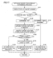
- step S78 A detailed description shown in this step S78 is displayed in a subroutine in Figure 17.
- the game processor 64 checks the state of the player's boxer, and determines whether or not the state of the player's boxer is "guard" in a step S132. That is, it is determined whether or not the player's boxer performs the right guard if the opponent boxer throws the left punch (right from a player's side), or whether or not the player's boxer performs the left guard if the opponent boxer throws the right punch (right from a player's side).
- step S132 the game processor 64 determines that the result of the punch of the opponent boxer is "guarded” in a step S133, and in succeeding step S134, sets the animation of the player's boxer to be displayed on the game screen 45 ( Figure 2) to "the punch is guarded”.
- step S132 determines that the result of the punch of the opponent boxer is "hit”. Then, in a next step S136, the game processor 64 calculates the damage of the player's boxer from the intensity of the punch (S100 in Figure 15) and the state at a time of being hit. Then, in a step S137, the calculated damage value is subtracted from the stamina value of the player's boxer.
- a step S138 the game processor 64 determines whether or not the stamina value of the player's boxer that subtracts the damage value by the punch of the opponent boxer is rendered equal to or smaller than "0" (zero). If “NO” is determined in the step S138, that is, in a case that the stamina value of the player's boxer that is equal to or larger than 1 is remained, in a step S139, as the animation of the player's boxer displayed on the game screen, "punch is hit” is set. On the contrary, when the stamina value of the player's boxer is run out, in the step S138, "YES" is determined. In this case, the game processor 64 sets the state of the player's boxer to "down” in a next step S140, and sets the animation of the player's boxer to "down after the punch is hit” in a step S141.
- step S77 after updating the location of the punch in the step S77, or after the result of the punch of the opponent boxer is processed in the step S78, the process advances to the succeeding step S75 so as to set the state of the opponent boxer to "neutral".
- the game processor 64 determines whether or not the predetermined time period is elapsed from starting averting in a next step S79. If “NO”, the process advances to the step S83. However, if "YES”, the process sets the state of the opponent boxer to "neutral” in the step S80.
- the game processor 64 determines whether or not the predetermined time period is elapse after being downed in the step S81. If “NO”, the process advances to the step S83, and if "YES”, the process sets the game state to "during being downed” in the step S82, and thereafter, advances to the step S83. In the step S83, the game processor 64 determines whether or not the remaining time period is 0 (zero), and if "YES", the game state is set to "determine result and display” in a step S84. However, if "NO”, an animation control for a game screen display is executed in the step S85.
- the voltage signal is extracted as the acceleration correlated signal generated in the piezoelectric buzzer element.
- the signal may be extracted as a current signal.
Abstract
Description
- The present invention relates to a boxing game system. More specifically, the present invention relates to a novel sensory boxing game system in which a globe-type inputting apparatus is attached to a hand, and by operating the inputting apparatus as if to actually play boxing in a real space, boxing is played against an opponent boxer displayed on a monitor screen.
- In the past, there are a number of home-use television games and arcade video games using boxing as a theme.
- The home-use television game is a television game in which, by operating a controller of a game machine by a finger, a player operates a character (boxer) in a screen. This lacks a real sensation or feeling of playing boxing.
- On the contrary, there is an arcade boxing game machine that by a retractable handle provided in the game machine, a kind and an intensity of a punch is input. It is possible to give the real sensation or feeling of boxing to the player in such the arcade game machine, and however, the game machine needs to be large in size due to mechanism, thus not possible to be used as the home-use game machine.
- Therefore, it is a primary object of the present invention to provide a novel sensory boxing game system.
- It is another object of the present invention to provide a home-use sensory boxing game system capable of playing a game while experiencing a real sensation of boxing.
- A boxing game system according to the present invention is a boxing game system, and comprises: an inputting apparatus swung in a real space, which is held by a hand of a game player, or attached to the hand of the game player, including an acceleration sensor for detecting a magnitude of a swing of the inputting apparatus, and a wireless transmitting means for transmitting in a wireless manner acceleration information detected by the acceleration sensor; a wireless receiving means for receiving the acceleration information transmitted by the wireless transmitting means; and a game processor for receiving the acceleration information received by the wireless receiving means, wherein the game processor determines an intensity of a punch based on the acceleration information.
- In a certain embodiment, the acceleration sensor may be a piezoelectric buzzer including a metal plate and a piezoelectric ceramic plate pasted on the metal plate, and outputs an acceleration correlated signal corresponding to a magnitude of the swing in a direction angular to a surface of the piezoelectric ceramic plate.
- In order to perform a wireless communication by an infrared light, the wireless transmitting means includes an infrared-light transmitting means, and the wireless receiving means includes an infrared-light receiving means.
- Furthermore, in a preferred embodiment, the inputting apparatus includes a boxing glove-shaped cushion member, and a main body provided to be integrated with the cushion member and held by the hand of the game player. In addition, the inputting apparatus includes a wristband provided to be integrated with the cushion member, and attached to a wrist of the game player.
- A glove-type inputting apparatus (34) shown in an embodiment includes a main body (40) held by a hand of a game player and swung in a real space, and in this main body, an acceleration sensor formed of a piezoelectric buzzer element (82) is accommodated, for example. When the game player swings the main body, that is, an inputting apparatus, as if to actually play boxing, acceleration information is detected by the acceleration sensor.
- An MCU (60) provided in the glove-type inputting apparatus drives an infrared LED (62) corresponding to the acceleration information. Therefore, the acceleration information is transmitted in a wireless manner.
- In an embodiment, an infrared light-receiving demodulating portion (32) is provided in a game machine (12), and the light-receiving demodulating portion receives an infrared light, and demodulates the acceleration information. The acceleration information is input into a game processor (64) provided in the game machine.
- The game processor displays a graphics of a boxer on a monitor, and changes a game screen corresponding to a game state. Furthermore, the game processor determines an intensity of the punch based on the acceleration information. In addition, the game processor, if required, calculates a damage value according to the intensity of the punch, calculates a stamina value of the boxer on the game screen from the damage value, and displays the stamina value.
- According to the present invention, the inputting apparatus is swung in the real space as if to actually play boxing so that the game is progressed, thus possible to realize a real sensory boxing game as if to actually play boxing for the game player. In addition, the acceleration information from the inputting apparatus is transmitted in a wireless manner to the game processor so that when swinging the inputting apparatus as if to actually play boxing, too, functionality of the inputting apparatus is not destroyed.
- The above described objects and other objects, features, aspects and advantages of the present invention will become more apparent from the following detailed description of the present invention when taken in conjunction with the accompanying drawings.
-
- Figure 1 is an illustrative view showing whole structure of a sensory boxing game system of one embodiment of the present invention;
- Figure 2 is an illustrative view showing one example of a game screen displayed on a television monitor in a Figure 1 embodiment;
- Figure 3 is a block diagram showing the Figure 1 embodiment;
- Figure 4 is an illustrative view showing internal structure of a glove-type inputting apparatus in the Figure 1 embodiment;
- Figure 5 is a circuit diagram showing the glove-type inputting apparatus;
- Figure 6 is a waveform diagram of each portion showing an operation of the glove-type inputting apparatus;
- Figure 7 is a flowchart showing whole structure of the Figure 1 embodiment;
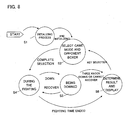
- Figure 8 is an illustrative view showing a state diagram of the Figure 1 embodiment;
- Figure 9 is a flowchart showing whole structure of an MCU of a Figure 4 embodiment;
- Figure 10 is a flowchart showing a specific operation of an acceleration detecting process shown in Figure 9;
- Figure 11 is a flowchart showing a specific operation of a code transmitting process in a Figure 9 embodiment;
- Figure 12 is a flowchart showing a specific operation of a code receiving process by a game processor in a Figure 7 embodiment;
- Figure 13 is a flowchart showing one portion of a specific operation of a during-the-fight process in the Figure 7 embodiment;
- Figure 14 is a flowchart showing a remaining portion of the specific operation of the during-the-fight process in the Figure 7 embodiment;
- Figure 15 is a flowchart showing a specific operation of a player's boxer behavior determining process by the game processor in a Figure 14 embodiment;
- Figure 16 is a flowchart showing one portion of the specific operation of the player' boxer behavior determining process by the game processor in the Figure 14 embodiment; and
- Figure 17 is a flowchart showing a specific operation of an opponent boxer punch result determining process by the game processor in the Figure 14 embodiment.
-
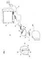
- Referring to Figure 1, a sensory
boxing game system 10, that is, one embodiment of the present invention, includes agame machine 12. A direct current (DC) power is supplied to thisgame machine 12 by anAC adapter 14. It is noted that this may be replaced by abattery 16. Furthermore, thegame machine 12 is connected to anAV terminal 18 of atelevision monitor 20 through anAV cable 22. - In addition, the
game machine 12 includes a housing, and above this housing, apower switch 24, adirection button 26, adetermination key 28, and acancel key 30 are provided. Thedirection button 26 has separate buttons for four directions (up and down, and right and left), and is used for moving a cursor in order to select a menu or a game mode on a display screen of thetelevision monitor 20, for example. Thedetermination key 28 is used for determining an input into thegame machine 12. Furthermore, the cancelkey 30 is used for canceling the input into thegame machine 12. - Furthermore, the
game machine 12 is provided with an infrared light-receivingportion 32, and this infrared light-receivingportion 32 receives an infrared signal from an infrared LED 62 (Figure 3, Figure 4) of a glove-type inputting apparatus 34 (34L, 34R) described later. - In this embodiment, two glove-
type inputting apparatuses 34 are used. The glove-type inputting apparatus 34 includes a portion (glove) 36 that is shaped like a boxing glove made of a cushion member covered by a nylon material, for example. In an edge portion on a near side of theglove 36, awristband 38 is mounted. Thewristband 38 is rendered opened and closed by a hook and loop fastener (trademark: Magic Tape), for example. In addition, in theglove 36, an inputting apparatusmain body 40 shown in detail in Figure 4 is mounted. - In the
main body 40, apower switch 42 and aguard key 44 are provided. Thepower switch 42 is a switch for turning on a power (not shown) when this glove-type inputting apparatus 34 is used. Theguard key 44 is a key switch for allowing a boxer on a player's side to perform a "left guard" or a "right guard" described later during a game play, and is used for guarding a punch from an opponent boxer. It is noted that thisguard key 44 offers an equivalent function to the above-described determination key 28 of thegame machine 12 at a time of "select a game mode and an opponent boxer" described later, and so forth. - The player holds left-handed and right-handed inputting apparatus
main bodies 40 by respective palms of the player's hand, pushes forward the inputtingapparatuses wristbands 38 worn around the wrist so as to play the sensory boxing game. At this time, theglove 36 functions as a cushion in order to prevent danger caused when the inputting apparatusmain body 40 is erroneously hit against atelevision 20 or an adjacent person, and in addition, theglove 36 is shaped like an actual boxing glove, thus effective to give a real sensation or feeling of playing boxing to the player. Furthermore, the glove-type inputting apparatus 34 is connected to the player's wrist by thewristband 38 so that even if the player erroneously releases themain body 40, the glove-type inputting apparatus 34 is not thrown out from the player's hand. - As described later, the glove-
type inputting apparatus 34 is provided with a piezoelectric buzzer element used as an acceleration sensor, and thegame machine 12 receives an acceleration correlated signal from the piezoelectric buzzer element so as to play the boxing game against anopponent boxer 46 on the game screen shown in Figure 2. - Referring to Figure 2, a
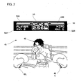
game screen 45 displayed on thetelevision monitor 20 in the sensoryboxing game system 10 is displayed as a graphic seen from a player's viewpoint, and the boxer on the player's side (player's boxer) is displayed by the glove. In thisgame screen 45, theopponent boxer 46 and thegloves 48L and 48R of the player's boxer are displayed as a moving image display-use object (sprite) together with one portion of a boxing ring. Above this image, one portion of a still image display-use object (text screen) is displayed in a predetermined manner. - At the center of an upper portion of the screen, a
round displaying portion 50 is formed, and in thisround displaying portion 50, the number of rounds and a remaining time-period are displayed. At the left of theround displaying portion 50, a player'sboxer displaying portion 52A is formed, and at the right, an opponent's displayingportion 52B is formed. In each of the displayingportions stamina value portions boxer displaying portion 52B, aname displaying portion 56 for displaying a name of the opponent boxer ("HIRO" in this embodiment) is further provided. It is noted that a displaying manner such as thisgame screen 45 is merely an example. - In this sensory
boxing game system 10, when the game player swings the glove-type inputting apparatus 34 corresponding to a movement of theopponent boxer 46 displayed on thegame screen 45 as if to play an actual boxing in a real space, a game processor 64 (Figure 4) detects the acceleration correlated signal from the piezoelectric buzzer element or a state of the guard key 44 (Figure 1) by the infrared signal transmitted from the infrared LED 62 (Figure 4) to the infrared light-receivingportion 32, and based on this, an intensity of the punch is calculated, a status of each boxer is changed, and so forth, for example. - It is noted that the left-handed glove-
type inputting apparatus 34L and the right-handed glove-type inputting apparatus 34R have the completely same structure as shown in this Figure 4 so that "L" indicating left-handed, and "R" indicating right-handed will be omitted unless otherwise specified. - The glove-
type inputting apparatus 34 includes anacceleration sensor circuit 58, theacceleration sensor circuit 58 includes apiezoelectric buzzer element 82 shown in Figure 4 described later and its associated circuit, and the acceleration correlated signal from thisacceleration sensor 58 is applied to theMCU 60. TheMCU 60 is 8 bits of a 1-chip microcomputer, for example, and converts the acceleration correlated signal from the piezoelectric buzzer element into a digital signal, and applies this digital signal to theinfrared LED 62. It is noted that in the glove-type inputting apparatus 34, the above-described guard key 44 (Figure 1) is further provided, and a state (value) of thisguard key 44 is also read by theMCU 60. - The digitally modulated infrared signals from each of the
infrared LEDs 62 of the two glove-type inputting apparatuses 34 is received by an infrared light-receivingdemodulating portion 32 of thegame machine 12, digitally demodulated, and then, input into thegame processor 64. One bit of this digital signal is transmitted as "1" or "0" corresponding to whether or not theguard key 44 is turned on or off, and therefore, thegame processor 64 is capable of recognizing whether "right guard" is set or "left guard" is set by checking the bit. - As the
game processor 64, an arbitrary kind of a processor is used. However, in this embodiment, a high-speed processor (trademark:XaviX) developed by the applicant of the present invention and already filed as a patent application is used. This high-speed processor is disclosed in detail in Japanese Patent Laying-open No.10-307790 [G06F13/36,15/78] and US Patent Application No.6,070,205 corresponding thereto. - Although not illustrated, in addition to various processors such as an operation processor, a graphic processor, a sound processor, a DMA processor, and etc., the
game processor 64 includes an A/D converter used for fetching an analog signal, and an input/output control circuit that receives an input signal such as an key operation signal and an infrared signal and applies an output signal to an external device. Therefore, the demodulated signal from the infrared light-receivingportion 32 and the input signal from the operation keys 26 -30 are applied to the operation processor via this input/output control circuit. The operation processor executes a necessary operation corresponding to the input signal, and applies a result to the graphic processor, and etc. Therefore, the graphic processor and the sound processor execute an image process and a sound process corresponding to the operation result. - It is noted that in a case that the
infrared LED 62 provided in themain body 40 of the glove-type inputting apparatus 34 forms one portion of a wireless transmitting means, the infrared light-receivingdemodulating portion 32 provided in thegame machine 12 is to form one portion of a wireless receiving means. It is noted that such the wireless transmitting means and the wireless receiving means may be a means that uses a normal radio wave, besides an infrared light. - In the
processor 64, aninternal memory 66 is provided, and theinternal memory 66 includes a ROM or a RAM (SRAM and/or DRAM). The RAM is used as a temporary memory, a working memory, or a counter or a register area (temporary data area), and a flag area. It is noted that the external memory 68 (ROM and/or RAM) is connected to theprocessor 64 through an external bus. A game program is stored to thisexternal memory 68 in advance. - The
processor 64 executes operations, graphic processes, sound processes, and etc., in each of the above-described processors according to the input signal from the infrared light-receivingdemodulating portion 32 and the operation keys 26 - 30, and outputs a video signal and an audio signal. The video signal is a signal composed of a text screen and a sprite image shown in Figure 2 described above, and the video signal and the audio signal are applied to thetelevision monitor 20 through theAV cable 22 and theAV terminal 18. Therefore, thegame screen 45 as shown in Figure 2 is displayed on the screen of thetelevision monitor 20, together with a necessary sound playing (sound effect, game music), for example. - The
main body 40 of the glove-type inputting apparatus 34 includes ahousing 70 molded of transparent (or translucent: transparency to light) plastic, and in thishousing 70, a concavity andconvexity 72 into which the fingers for holding thehousing 70 fit with each other is formed. Inside thehousing 70, amain board 74 is stored, and on thisboard 74, the above-describedMCU 60 is mounted. In addition, on themain board 74, thepower switch 42 is further provided, and in addition, oneinfrared LED 62 is fixed. Anotherinfrared LED 62 is fixed on an upper portion of thehousing 70. - A
piezoelectric buzzer case 76 is mounted between thesubstrate 74 and theabove LED 62 within thehousing 70, and in thispiezoelectric buzzer case 76, a mountingportion 78 is formed. Within the mountingportion 78, thepiezoelectric buzzer element 82 is mounted via arubber packing 80. Thispiezoelectric buzzer element 82 forms the acceleration sensor circuit 58 (Figure 5). - As well known, the
piezoelectric buzzer element 82 includes aceramic plate 86 pasted on ametal plate 84, and if a power voltage is applied between themetal plate 84 and an electrode on theceramic plate 86, a buzzer sound is generated. In this embodiment, thepiezoelectric buzzer element 82 thus structured is used as the acceleration sensor. That is, theceramic plate 84 is a piezoelectric ceramic, and it is well known that when a stress is worked onto the piezoelectric ceramic, an electric signal is generated from the piezoelectric ceramic. As a consequence, in this embodiment, corresponding to a movement (right and left movement in Figure 4, that is, a direction angular to a surface of the piezoelectric buzzer) of thepiezoelectric buzzer element 82, that is, the glove-type inputting apparatus 34, the electric signal generated in theceramic plate 86 is fetched between themetal plate 84 and the above-described electrode. However, in this embodiment, as described later, as a result of a predetermined digital signal process being performed according to the electric signal, an acceleration correlated digital signal or data is to be fetched by theMCU 60. - At an oblique surface of an upper edge of the
housing 70, the above-described guard key 44 is mounted. - Referring to Figure 5, the
piezoelectric buzzer element 82 described above is included in theacceleration sensor circuit 58. In addition, in theMCU 60, an externally attached oscillatingcircuit 88 is provided for theMCU 60, and theMCU 60 operates in response to a clock signal from thisoscillating circuit 88. - Then, the
MCU 60 outputs a rectangular-shaped waveform signal from anoutput port 0, and applies this signal to oneelectrode 82a of thepiezoelectric buzzer element 82 through 10 kilo ohms of a resistance, for example. Theelectrode 82a of thepiezoelectric buzzer element 82 may be the above-describedmetal plate 84, and is grounded via acapacitor 90 such as 0.1 µF, for example. Furthermore, adiode circuit 94 is connected to theelectrode 82a, and a fluctuation band of the voltage is thereby rendered within a predetermined range. - The
other electrode 82b of thepiezoelectric buzzer element 82 is connected to aninput port 0 of theMCU 60, and in addition, connected to thediode circuit 94. Thereby, the fluctuation band of the voltage is rendered within the predetermined range. It is noted that the twoelectrodes piezoelectric buzzer element 82 is electrically separated by a relativelyhigh resistance 96 such as 1 Mega ohms, for example. - When the rectangular-shaped waveform signal shown in Figure 6 (A) is applied to the
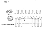
electrode 82a of thepiezoelectric buzzer element 82, concurrent with a charge and discharge of thecapacitor 90, a triangular waveform signal as in Figure 7 (B) is input into theinput port 0 of theMCU 60. It is noted that a size (waveform high value) of the rectangular-shaped waveform signal and a size (waveform high value) of the triangular waveform signal are restrained by thediode circuits - When the glove-type inputting apparatus 34 (Figure 4) is stationary, that is, when the
apparatus 34 is not displaced, a level on a minus side of the triangular waveform signal does not change as shown in a left edge of Figure 7 (B). However, if the glove-type inputting apparatus 34 is displaced by the operator to a right or left direction in a three-dimensional real space in Figure 4, due to a piezoelectric effect concurrent with the displacement, a voltage is produced in thepiezoelectric buzzer element 82. The acceleration correlated voltage biases the level on the minus side of the triangular waveform signal. Thus, if the glove-type inputting apparatus 34 is displaced, the acceleration correlated voltage at a level corresponding to the size of the displacing acceleration is produced to thepiezoelectric buzzer element 82. Therefore, the level on the minus side of the triangular waveform signal input into theinput port 0 of theMCU 60 varies corresponding to a level of the acceleration correlated voltage as shown in Figure 7 (B). - As described later, the
MCU 60 converts a level change on the minus side of such the triangular waveform signal into acceleration data or acceleration correlated data, and drives the LED 62 (Figure 3) corresponding to the acceleration data. - Herein, referring to Figure 7 and 8, a schematic operation of the sensory
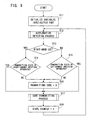
boxing game system 10 of the Figure 1 embodiment will be described. The power switches 24 and 42 shown in Figure 1 are turned on so as to start the game. Firstly, thegame processor 64 shown in Figure 3 executes an initializing process in a step S1. More specifically, a system hardware and each variable are initialized. - Thereafter, the
game processor 64 updates the image signal in a step S2 in Figure 7 and 8 so as to update the image displayed on themonitor 20. It is noted that this displayed image updating is executed by each 1 frame (television frame or video frame). - Then, the
game processor 64 executes a process corresponding to the game state. However, the process to be done first is "select game mode and opponent boxer". In this selection of the game mode and the opponent boxer, the operator or the game player operates aselection key 26 shown in Figure 1 in a step S3 in Figure 7 and 8 so as to selectively set the game mode, a level of difficulty of the game, and the opponent boxer. - In the actual boxing game of "during the fight" state shown in a step S4 in Figure 7 and 8, each boxer fights with punches against each other. In a case that the boxer is hit by the punch, and knocked down, a "down time process" is executed in a step S5 in Figure 7 and Figure 8.
- In the down time process, when the boxer on a game player side (the player's boxer) is knocked down, the stamina value is restored at each time that the inputting
apparatus 34 is swung, and if the stamina value reaches a predetermined value in 10 counts or earlier, the boxer is returned to the game state of the during the fight in the preceding step S4. Otherwise, the boxer moves to a game state of "determine result and display process" shown in a step S6 in Figure 7 and Figure 8. To the contrary, when the opponent boxer is knocked down, a returning or end fight is determined based on a behavior algorism of the opponent boxer. - It is noted that in the "determine result and the display" process, a victory-or-defeat determination in a case that the time runs out, and a display of a result of the fight are performed. It is noted that although the during-the-fight process shown in the step S4 will be described in detail by referring to a flowchart later, a detailed flowchart of the steps S5 and S6 are omitted.
- Thereafter, if there is a video synchronizing interruption, an image updating of the step S2 (Figure 7) is executed. In addition, the sound process of a step S8 in Figure 7 is executed when a sound interruption occurred, and the game music and the sound effect are thereby output. When an interruption other than interruptions for the sound process occurred, the
game processor 64 receives the infrared signal (code) input from the infrared light-receivingportion 32 in a step S9 in Figure 7. - Referring to Figure 9, Figure 9 shows a whole operation of the
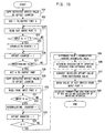
MCU 60 of the glove-type inputting apparatus 34, and in a first step S11, theMCU 60 initializes variables that theMCU 60 handles such as a detection offset value, an offset counter, and etc., described later, and in addition, initializes the input port and the output port (Figure 5). - Thereafter, via an acceleration detecting process (described in detail later) in a step S12, the
MCU 60 determines whether the glove-type inputting apparatus 34 is the right-handed inputting apparatus 34R or the left-handed inputting apparatus 34L. If a specific input port of theMCU 60 is set to "1", theapparatus 34 is the right-handed inputting apparatus 34R, and if "0", theapparatus 34 is the left-handed inputting apparatus 34L in a step S13 so that the specific input port of theMCU 60 needs to be sensed in the step S13. Then, it is determined whether or not the current state is the transmitting state in a step S13. If "YES" in the step S13, that is, in a case of the right-handed inputting apparatus 34R, the determination is made in a step S14, and if "NO" in the step S13, that is, in a case of the left-handed inputting apparatus 34L, the determination is made in a step S15. - Although not illustrated, the
MCU 60 has a state counter as a software counter, and the transmitting state is established at each time that this state counter becomes a predetermined value. Therefore, it is detected whether or not this state counter is rendered the predetermined value in the steps S14 and S15. In a case of "NO" in the step S14 or S15, the transmitting code is rendered "0" in a step S16, or in a case of "YES" in the step S14 or S15, the process directly advances to a code transmitting process (described in detail later) in a step S17. After executing the code transmitting process in the step S17, the process increments (+1) the state counter (not shown) in a step S18, and then, returns to the step S12. It is noted that as described later, the code transmitting process is performed in a bit serial, and a necessary time-period for transmitting 1 bit is approximately some micro seconds, that is, extremely short period of time. - Figure 10 is a flowchart showing in detail the step S12 in Figure 9, and in a first step S21 of this acceleration detecting process, the
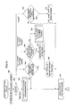
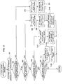
MCU 60 copies to the offset counter (not shown) a detected offset value set to the register (not shown). The "detected offset value" is a value for inputting in an equal manner in time a high level and a low level of a rectangular waveform determination shown in Figure 6 (A) when no voltage is generated in thepiezoelectric buzzer element 82, and this detected offset value is set to an arbitrary default value at a time of starting the operation. - In a step S22 that follows the step S21, the
MCU 60 sets "1" to theoutput port 0. That is, "1", that is, the high level, is output. Next, in a step S23, theMCU 60 reads data from theinput port 0. - In a step S24, it is determined whether or not the data of the
input port 0 read in the step S23 is "1". If "YES", theMCU 60 increments (+1) an accumulating counter (not shown) in a succeeding step S25. The "accumulating counter" is a counter for calculating a period during which the high level is being read, incremented when the input port is "1" or the high level, and is left intact when the input port is "0". - In a case of incrementing the accumulating counter in the step S25, or in a case of determining "NO" in the step S24, in a succeeding step S26, the
MCU 60 increments the offset counter, and determines whether or not the count value of the offset counter reaches the predetermined value in a next step S27. That is, as long as "NO" is determined in this step S27 after setting "1" to theoutput port 0 in the step S22, theMCU 60 continuously outputs "1" of theoutput port 0. - Furthermore, in a case that the count value of this offset counter reaches the predetermined value in the step S27, in a succeeding step S28, the
MCU 60 sets "0", that is, the low level, to theoutput port 0. In a succeeding step S29, theMCU 60 copies to the offset counter the detected offset value set to the register. - In a succeeding step S30, the
MCU 60 reads the data from theinput port 0. In a step S31, it is determined whether or not the data of theinput port 0 read in the step S30 is "1". If "YES", theMCU 60 increments (+1) the accumulating counter in a next step S32. - In a case of incrementing the accumulating counter in the step S32, or in a case of determining "NO" in the step S31, the
MCU 60 decrements (-1) the offset counter in a succeeding step S33, and determines whether or not the count value of the offset counter reaches 0 (zero) in a next step S34. That is, as long as "NO" is determined in this step S34 after setting "0" to theoutput port 0 in the step S28, theMCU 60 continuously outputs "0" of theoutput port 0. - Then, if "YES" is determined in the step S34, that is, if the offset counter is rendered zero (0), in a succeeding step S35, the
MCU 60 subtracts an intermediate value from the count value of the accumulating counter so as to evaluate the difference. Herein, the intermediate value is "N/2" where "N" is the total number of repetitions of the number of repetitions for the high level detection returning from the step S27 to the step S23, and the number of repetitions for the low level detection returning from the step S34 to the step S30. The reason why the difference is evaluated by using the intermediate value in this step S35 is that a ratio (duty 50%) of a period between the high level and the low level of an ideal piezoelectric buzzer element, and in a state that no acceleration correlated voltage is generated in the piezoelectric buzzer element is used as a reference for determining the acceleration. - To be described in detail, a count value of the accumulating counter is the number of reading "1" or the high level into the
input port 0 as described above, and in a case of being the ideal piezoelectric buzzer element and that no voltage is generated, the difference of the "accumulated counter intermediate value" is supposed to be zero (0). Therefore, in a case that any voltage is generated to thepiezoelectric buzzer element 82, a meaningful value is obtained as the difference. Herein, in a step S36, a displacing acceleration of the glove-type inputting apparatus 34 is determined according to this difference value. Basically, data that multiplies the difference value data by a predetermined coefficient is the acceleration data or the acceleration correlated data. - Thereafter, in a step S37, the detected offset value is corrected based on the difference value evaluated in the step S35. That is, in an initial state, the game player or the operator does not swing the glove-
type inputting apparatus 34 so that the acceleration correlated voltage is not generated in thepiezoelectric buzzer element 82. In spite thereof, the meaning that the difference value that is not 0 (zero) is detected in the step S35 is that the set detected offset value set in the step S21 is not correct, in view of a characteristic of the piezoelectric buzzer element used for the glove-type inputting apparatus. That is, this means that the piezoelectric buzzer element is not the ideal piezoelectric buzzer element. As a consequence, in such the case, in order to correct the bias of a characteristic of each piezoelectric buzzer element from the characteristic of an ideal piezoelectric buzzer element, the detected offset value is made to be corrected according to the difference value in the step S37. - On the other hand, if the detected offset value is always made to be changed or to be corrected in the step S37, even if the piezoelectric buzzer element is the difference value that as a result of the acceleration correlated voltage being actually generated, the detected offset value is to be corrected. However, a voltage generating period of the piezoelectric buzzer element is very short compared to other periods. Thus, there is no problem if the step S37 is executed at each time that the difference value is detected. That is, a proper correction is made at a time of starting an actual boxing game so that even if the step S37 is subsequently executed at each time that the acceleration is detected, there occurs no large variance to the detected offset value, thus no problem to the actual boxing game.
- In a succeeding step S38, the
MCU 60 reads from theinput port 1 the value "1" or "0" of the key switch, that is, theguard key 44, and in a succeeding step S39, theMCU 60 further adds a parity bit based on the value from theguard key 44 and the displacing acceleration or a moving acceleration of the glove-type inputting apparatus 34 determined in the preceding step S36, calculates the transmission code, and then, returns to the step S13 (Figure 9) of a main routine. - Herein, referring to Figure 11, a description will be made regarding the code transmission from the glove-
type inputting apparatus 34 to thegame processor 64 in the step S17 (Figure 9). In a first step S41, theMCU 60 copies the transmission code created in the step S12 or step S16 to a temporary data register (not shown). Then, it is determined whether or not the most significant bit is "1". If the most significant bit is "1", "YES" is determined in a step S42, and in a succeeding step S43, theMCU 60 sets "1" to theoutput port 1, and turns on the infrared LED 62 (Figure 3). Thereafter, a predetermined waiting time-period is elapsed in a step S44. However, if "NO" in the step S42, that is, if the most significant bit is "0", the process directly advances to the step S44. - After the predetermined waiting time-period is elapsed in the step S44, in a step S45, the
MCU 60 sets "0" to theoutput port 1, and turns off theinfrared LED 62. Thereafter, the predetermined waiting time-period is elapsed in a step S46. - After the predetermined waiting time-period is elapsed in the step S46, the
MCU 60 makes a left shift by 1 bit, and renders the bit that has been a least significant bit in a step S47. That is, a transmission bit is exchanged for a bit serial transmission. Then, in a step S48, it is determined whether or not the transmission of all bits is completed. If "NO", the process returns to the step S42, and if "YES", the process is ended, and then, advances to the step S18 shown in Figure 9. - Herein, referring to Figure 12, a description will be made regarding a code receiving process by the
game processor 64 shown in the step S9 in Figure 7. In the code receiving process, for the process to be processed by a timer interruption, thegame processor 64 determines whether or not there is a timer interruption in a first step S51. Unless the timer interruption, this is an interruption started by a transmission start bit. If "NO", the timer interruption is set in a step S52, and if "YES", the process directly advances to a step S53. - In the step S53, the
game processor 64 retains a code receiving-use temporary data area within the internal memory 66 (Figure 3). Then, in a succeeding step S54, data of the input port having the output signal being input from the infrared light-receivingportion 32 is read. In a succeeding step S55, thegame processor 64 applies a right shift to the temporary data, and renders the data read in the step S54 the least significant bit of the temporary data. - Thereafter, it is determined whether or not it is completed to receive all bits in a step S56, and if "NO", a next time interruption is waited in a step S57. If "YES", the timer interruption is cancelled in a step S58, and in a step S59, the temporary data is copied as the receiving code. The
game processor 64 uses this receiving code so as to execute the game process in Figure 7. - As shown in preceding Figure 7, after selecting the game mode in the step S3, the
game processor 64 executes a "during the fight" process in the next step S4. More specifically, this during-the-fight process is executed according to a flowchart shown in Figure 13 and Figure 14. - In a first step S61 of the during-the-fight process, the
game process 64 checks a state of the player's boxer so as to determine the state in the step S62. If this state is a "neutral", the process executes a player's boxer behavior determining process in a step S63. - Herein, referring to Figure 15, a detailed description will be made regarding a subroutine in this step S63. In a first step S91 in Figure 15, the
game processor 64 checks the input data from the glove-type inputting apparatus 34 obtained as a result of the receiving process in Figure 12 so as to determine whether or not there is the acceleration signal input from the left-handed inputting apparatus 34L in a step S92, whether or not there is the acceleration signal input from the right-handed inputting apparatus 34R in a step S93, whether or not theguard key 44 of the left-handed inputting apparatus 34L is depressed in a step S94, and whether or not theguard key 44 of the right-handed inputting apparatus 34R in a step S95, respectively. - If "YES" is determined in the step S92, that is, if the acceleration signal is input from the left-
handed inputting apparatus 34L, thegame processor 64 sets a "left punch" as the state of the player's boxer in a succeeding step S96, and sets the "left punch" as an animation of the player's boxer to be displayed on thegame screen 45 at that time. - If "YES" is determined in the step S93, that is, if the acceleration signal is input from the right-
handed inputting apparatus 34R, thegame processor 64 sets a "right punch" as the state of the player's boxer in a succeeding step S98, and sets the "right punch" as an animation of the player's boxer to be displayed on thegame screen 45 at that time. - After the step S97 or S99, that is, after the "left punch" or the "right punch" is set, the
game processor 64 determines an "intensity of the punch" of the left punch or the right punch from a magnitude of the acceleration at that time in a step S100. In this step S100, more specifically, thegame processor 64 calculates from the magnitude of the acceleration the intensity of the punch according to the predetermined coefficient for the conversion. - If "YES" is determined in the step S94, that is, if the
guard key 44 of the left-handed inputting apparatus 34L is turned on, thegame processor 64 sets a "left guard" as the state of the player's boxer in a succeeding step S101, and sets a "left guard" as the animation of the player's boxer to be displayed at that time on thegame screen 45 in a step S102. - Then, if "YES" is determined in the step S95, that is, if an on signal of the
guard key 44 is input from the right-handed inputting apparatus 34R, thegame processor 64 sets the "right guard" as the state of the player's boxer in a succeeding step S103, and sets the "right guard" as the animation of the player's boxer to be displayed at that time on thegame screen 45. - Thus, in the player's boxer behavior determining process in the step S63, according to the input signal (information) from the
input apparatus 34, only the state (in a case of the punch, the intensity is included) of the player's boxer (boxer of the game player), and the setting of the animation are performed. - Referring to Figure 13, when it is determined that the state of the player's boxer is the "left guard" or the "right guard" in the step S62, the
game processor 64 determines whether or not the predetermined time period is elapsed after starting the guard in a succeeding step S64. If "NO", the process advances to a step S71, and if "YES", the state of the player's boxer is set to the "neutral" in a step S65. That is, in a case that the predetermined time period is elapsed after theguard key 44 is depressed, the state of the player's boxer is returned to the "neutral". - If it is determined that the state of the player's boxer is the "left punch" or the "right punch" in the step S62, the
game processor 64 determines whether or not the punch of the player's boxer reaches a location of the opponent boxer in a next step S66. If "NO", the location of the punch is updated in a step S67, and if "YES", a result determining process of the punch of the player's boxer is executed in the step S68. - The detailed process shown in this step S68 is shown in a subroutine in Figure 16. In a first step S111, the
game processor 64 checks the state of the opponent boxer, and in a step S112, it is determined whether or not the state of the opponent boxer is an "avert". If "YES" is determined, in a succeeding step S113, thegame processor 64 determines that the result of the punch of the player's boxer is a "miss swing". - If "NO" in the step S112, it is determined whether or not the state of the opponent boxer is the "guard" in a next step S114. That is, it is determined whether or not the opponent boxer performs the left guard (right from a player's side) if the player's boxer throws the right punch, or whether or not the opponent boxer performs the right guard (left from a player's side) if the player's boxer throws the left punch. If "YES" is determined in this step S114, the
game processor 64 determines that the result of the punch of the player's boxer is the "guarded" in a step S115, and sets to "the punch is guarded" the animation of the opponent boxer to be displayed on the game screen 45 (Figure 2) in a succeeding step S116. - If "NO" is determined in the step S114, in a next step S117, the
game processor 64 determines that the result of the punch of the player's boxer is "hit". Then, in a next step S118, thegame processor 64 calculates a damage of the opponent boxer from the intensity of the punch (step S100 in Figure 15) and the state at a time of being hit. Then, the calculated damage value is subtracted from the stamina value of the opponent boxer (step S119). - In a step S120, the
game processor 64 determines whether or not the stamina value of the opponent boxer having the damage value by the punch of the player's boxer subtracted is rendered equal to or smaller than "0" (zero). In a case of determining "NO" in this step S120, that is, in a case that the stamina value that is equal to or more than 1 is remained as the stamina value of the opponent boxer, in a step S121, as the animation of the opponent boxer to be displayed on the game screen, "the punch is hit" is set. On the contrary, if the stamina value is run out, "YES" is determined in the step S120, and in this case, thegame processor 64 sets the state of the opponent boxer to "down" in a next step S122. The animation of the opponent boxer is set to "down after the punch is hit" in a step S123. - Thus, when the punch of the player's boxer reaches the opponent boxer, as a result of the punch, it is determined what has become of the opponent boxer in the step S68.
- Returning to Figure 13 once again, after the location of the punch is updated in the step S67, or after the result of the punch of the player's boxer is processed in the step S68, the process advances to the succeeding step S65 so as to set the state of the player's boxer to "neutral".
- When it is determined that the state of the player's boxer is "down" in the step S62, the
game processor 64 determines whether or not the predetermined time period is elapsed after the down in a step S69. If "NO", the process advances to the step S71, and if "YES", the game state is set to "being downed" in a step S70. - After the step S63, the step S65, or the step S70, the process advances to the step S71. In the step S71, the
game processor 64 checks the state of the opponent boxer. Thereafter, a similar operation to the case of determining the state of the player's boxer described before is performed. However, the state "avert" exists in the opponent boxer, in a case of the behavior determination of the player's boxer described before, no "avert" exists. Therefore, although "avert" exists in steps S73 - S82, the process is basically similar to the preceding steps S62 - S70. - In a first step S72 in Figure 14, the
game processor 64 determines the state of the opponent boxer. If this state is "neutral", in the step S73, based on the behavior algorism similar to the behavior determining process of the player's boxer shown in Figure 15, an opponent-boxer behavior determining process is executed, for example. - Then, it is determined that the state of the opponent boxer is "left guard" or "right guard" in the step S72, the
game processor 64 determines whether or not the predetermined time period is elapsed after starting the guard in a next step S74. If "NO", the process advances to the step S83, and if "YES", the state of the opponent boxer is set to "neutral" in the step S75. - If it is determined that the state of the opponent boxer is "left punch" or "right punch" in the step S72, the
game processor 64 determines whether or not the punch of the opponent boxer reaches the location of the player's boxer in a next step S76. If "NO" , the location of the punch of the opponent boxer is updated in the step S77, and if "YES", the result determining process of the punch of the opponent boxer is executed in the step S78. - A detailed description shown in this step S78 is displayed in a subroutine in Figure 17. In a first step S131, the
game processor 64 checks the state of the player's boxer, and determines whether or not the state of the player's boxer is "guard" in a step S132. That is, it is determined whether or not the player's boxer performs the right guard if the opponent boxer throws the left punch (right from a player's side), or whether or not the player's boxer performs the left guard if the opponent boxer throws the right punch (right from a player's side). If "YES" is determined in this step S132, thegame processor 64 determines that the result of the punch of the opponent boxer is "guarded" in a step S133, and in succeeding step S134, sets the animation of the player's boxer to be displayed on the game screen 45 (Figure 2) to "the punch is guarded". - If "NO" is determined in the step S132, in a next step S135, the
game processor 64 determines that the result of the punch of the opponent boxer is "hit". Then, in a next step S136, thegame processor 64 calculates the damage of the player's boxer from the intensity of the punch (S100 in Figure 15) and the state at a time of being hit. Then, in a step S137, the calculated damage value is subtracted from the stamina value of the player's boxer. - In a step S138, the
game processor 64 determines whether or not the stamina value of the player's boxer that subtracts the damage value by the punch of the opponent boxer is rendered equal to or smaller than "0" (zero). If "NO" is determined in the step S138, that is, in a case that the stamina value of the player's boxer that is equal to or larger than 1 is remained, in a step S139, as the animation of the player's boxer displayed on the game screen, "punch is hit" is set. On the contrary, when the stamina value of the player's boxer is run out, in the step S138, "YES" is determined. In this case, thegame processor 64 sets the state of the player's boxer to "down" in a next step S140, and sets the animation of the player's boxer to "down after the punch is hit" in a step S141. - Returning to Figure 14, after updating the location of the punch in the step S77, or after the result of the punch of the opponent boxer is processed in the step S78, the process advances to the succeeding step S75 so as to set the state of the opponent boxer to "neutral".
- In a case of determining that the state of the opponent boxer is "avert" in the step S72, the
game processor 64 determines whether or not the predetermined time period is elapsed from starting averting in a next step S79. If "NO", the process advances to the step S83. However, if "YES", the process sets the state of the opponent boxer to "neutral" in the step S80. - Then, in addition, when it is determined that the state of the opponent boxer is "down" in the step S72, the
game processor 64 determines whether or not the predetermined time period is elapse after being downed in the step S81. If "NO", the process advances to the step S83, and if "YES", the process sets the game state to "during being downed" in the step S82, and thereafter, advances to the step S83. In the step S83, thegame processor 64 determines whether or not the remaining time period is 0 (zero), and if "YES", the game state is set to "determine result and display" in a step S84. However, if "NO", an animation control for a game screen display is executed in the step S85. - It is noted that in the above embodiment, the voltage signal is extracted as the acceleration correlated signal generated in the piezoelectric buzzer element. However, the signal may be extracted as a current signal.
- Although the present invention has been described and illustrated in detail, it is clearly understood that the same is by way of illustration and example only and is not to be taken by way of limitation, the spirit and scope of the present invention being limited only by the terms of the appended claims.
Claims (5)
- A boxing game system, comprising:an inputting apparatus swung in a real space, which is held by a hand of a game player; or attached to the hand of the game player, including an acceleration sensor for detecting a magnitude of a swing of said inputting apparatus, and a wireless transmitting means for transmitting in a wireless manner acceleration information detected by said acceleration sensor;a wireless receiving means for receiving the acceleration information transmitted by said wireless transmitting means; anda game processor for receiving the acceleration information received by said wireless receiving means, whereinsaid game processor determines an intensity of a punch based on said acceleration information.
- A boxing game system according to claim 1, wherein said acceleration sensor is a piezoelectric buzzer including a metal plate and a piezoelectric ceramic plate pasted on said metal plate, and outputs an acceleration correlated signal corresponding to a magnitude of said swing in a direction angular to a surface of said piezoelectric ceramic plate.
- A boxing game system according to claim 1 or 2, wherein said wireless transmitting means includes an infrared-light transmitting means, and said wireless receiving means includes an infrared-light receiving means.
- A boxing game system according to any one of claims 1 to 3, wherein said inputting apparatus includes a boxing glove-shaped cushion member, and a main body provided to be integrated with said cushion member and held by the hand of the game player.
- A boxing game system according to any one of claims 1 to 4, wherein inputting apparatus includes a wristband provided to be integrated with said cushion member, and attached to a wrist of the game player.
Applications Claiming Priority (3)
| Application Number | Priority Date | Filing Date | Title |
|---|---|---|---|
| JP2002209201A JP3865663B2 (en) | 2002-07-18 | 2002-07-18 | Boxing game system |
| JP2002209201 | 2002-07-18 | ||
| PCT/JP2003/008742 WO2004009196A1 (en) | 2002-07-18 | 2003-07-09 | Boxing game system |
Publications (2)
| Publication Number | Publication Date |
|---|---|
| EP1524015A1 true EP1524015A1 (en) | 2005-04-20 |
| EP1524015A4 EP1524015A4 (en) | 2010-11-17 |
Family
ID=30767678
Family Applications (1)
| Application Number | Title | Priority Date | Filing Date |
|---|---|---|---|
| EP03741301A Withdrawn EP1524015A4 (en) | 2002-07-18 | 2003-07-09 | Boxing game system |
Country Status (8)
| Country | Link |
|---|---|
| US (1) | US7371164B2 (en) |
| EP (1) | EP1524015A4 (en) |
| JP (1) | JP3865663B2 (en) |
| KR (1) | KR100932593B1 (en) |
| CN (1) | CN100384494C (en) |
| AU (1) | AU2003281500A1 (en) |
| TW (1) | TWI288014B (en) |
| WO (1) | WO2004009196A1 (en) |
Cited By (1)
| Publication number | Priority date | Publication date | Assignee | Title |
|---|---|---|---|---|
| EP1870141B1 (en) * | 2006-06-20 | 2020-05-20 | Nintendo Co., Ltd. | Recording medium recording game program and game apparatus |
Families Citing this family (46)
| Publication number | Priority date | Publication date | Assignee | Title |
|---|---|---|---|---|
| US7682237B2 (en) * | 2003-09-22 | 2010-03-23 | Ssd Company Limited | Music game with strike sounds changing in quality in the progress of music and entertainment music system |
| JP4397741B2 (en) * | 2004-06-11 | 2010-01-13 | 株式会社コナミデジタルエンタテインメント | Game device |
| CN101068605B (en) * | 2004-12-03 | 2011-07-13 | 新世代株式会社 | Boxing game processing method, display control method, position detection method, cursor control method, energy consumption calculating method and exercise system |
| JP2006185109A (en) * | 2004-12-27 | 2006-07-13 | Hitachi Ltd | Image measurement device and image measurement method |
| KR100659888B1 (en) * | 2005-01-07 | 2006-12-20 | 엘지전자 주식회사 | 3d video processing system of mobile device |
| JP4372083B2 (en) * | 2005-10-28 | 2009-11-25 | 株式会社コナミデジタルエンタテインメント | Game system and game machine |
| US7874918B2 (en) * | 2005-11-04 | 2011-01-25 | Mattel Inc. | Game unit with motion and orientation sensing controller |
| US8574050B2 (en) | 2005-11-04 | 2013-11-05 | Mattel, Inc. | Game unit with dual joystick controllers |
| JP5089079B2 (en) * | 2006-05-08 | 2012-12-05 | 任天堂株式会社 | Program, information storage medium, and image generation system |
| JP4700584B2 (en) * | 2006-09-21 | 2011-06-15 | 株式会社ソニー・コンピュータエンタテインメント | Information processing apparatus, information processing method, and program |
| CN101209382B (en) * | 2006-12-27 | 2010-06-23 | 鸿富锦精密工业(深圳)有限公司 | Action sensing device |
| US20080207325A1 (en) * | 2007-02-27 | 2008-08-28 | Hsu Kent T J | Control arrangement for operating video game console |
| JP5420824B2 (en) * | 2007-03-30 | 2014-02-19 | 任天堂株式会社 | GAME DEVICE AND GAME PROGRAM |
| WO2008126419A1 (en) * | 2007-04-10 | 2008-10-23 | Ssd Company Limited | Exercise supporting method |
| US8475274B2 (en) | 2007-04-26 | 2013-07-02 | Sony Computer Entertainment America Llc | Method and apparatus for dynamically adjusting game or other simulation difficulty |
| TWI395604B (en) * | 2007-05-03 | 2013-05-11 | Pixart Imaging Inc | Interactive game method and system with anti - sports injury function |
| JP4327868B2 (en) | 2007-06-29 | 2009-09-09 | 株式会社コナミデジタルエンタテインメント | GAME DEVICE, GAME CONTROL METHOD, GAME CONTROL PROGRAM, AND COMPUTER-READABLE RECORDING MEDIUM CONTAINING THE PROGRAM |
| KR100943039B1 (en) * | 2008-06-12 | 2010-02-19 | 한국과학기술원 | Multi-Game Supporting System using Body-Attached Sensors and Digital Sport Equipments |
| US8461468B2 (en) | 2009-10-30 | 2013-06-11 | Mattel, Inc. | Multidirectional switch and toy including a multidirectional switch |
| EP2592998B1 (en) * | 2010-07-15 | 2018-12-19 | The Cleveland Clinic Foundation | Enhancement of the presentation of an athletic event |
| US10398959B2 (en) | 2012-03-02 | 2019-09-03 | Clarence V. Hall | Multi-head, multi-abdomen, multi-armed apparatus for use with a slip and counter fight simulation / workout machine or stand alone device for fight simulation |
| US9050518B2 (en) | 2013-02-28 | 2015-06-09 | Clarence V. Hall | Slip and counter fight simulation / workout machine |
| US10493346B2 (en) | 2012-03-02 | 2019-12-03 | Clarence V. Hall | Multi-headed, multi-abdomen, multi-armed apparatus for use with a slip and counter fight simulation / workout machine or stand alone device for fight simulation |
| US9044659B2 (en) | 2012-03-02 | 2015-06-02 | Clarence V. Hall | Slip and counter fight simulation / workout machine |
| US9821208B2 (en) | 2014-03-20 | 2017-11-21 | Clarence V. Hall | Multi-headed, multi-abdomen, multi-armed apparatus for use with a slip and counter fight simulation/workout machine or stand alone device for fight simulation |
| US20130282155A1 (en) * | 2012-03-23 | 2013-10-24 | Man On Li | Methods, systems, and devices for collecting and analyzing movement data of an athlete |
| KR101326349B1 (en) * | 2012-05-30 | 2013-11-11 | 유실근 | Smart grip exercise machine |
| US8696422B1 (en) | 2012-07-20 | 2014-04-15 | Rafael Santiago | Electronic boxing game, gear, method and systems |
| CN103721406A (en) * | 2012-10-11 | 2014-04-16 | 成都哆可梦网络科技有限公司 | Multi-side interaction boxing game system based on mobile Internet |
| TWI468212B (en) * | 2012-11-09 | 2015-01-11 | Borden Technology Corp | Gaming system and method for boxing machine |
| WO2014157755A1 (en) * | 2013-03-29 | 2014-10-02 | 엘지전자 주식회사 | Game device and method for driving same |
| KR101537866B1 (en) * | 2013-12-06 | 2015-07-23 | 주식회사 스타폴 | electronic equipment for controlling fighting competition |
| CN104368147A (en) * | 2014-10-24 | 2015-02-25 | 苏州德鲁森自动化系统有限公司 | Motion sensing game system control method |
| US9931560B2 (en) * | 2014-12-22 | 2018-04-03 | H. Carnell Caroll-James | Shadow gloves |
| CN105457255A (en) * | 2016-01-13 | 2016-04-06 | 薛晓东 | Boxing glove and movement data processing method and device |
| US10702770B2 (en) * | 2016-05-03 | 2020-07-07 | Disney Enterprises, Inc. | System and method of configuring disparate physical objects to provide control signals for controlling a game |
| JP6877893B2 (en) * | 2016-06-06 | 2021-05-26 | 任天堂株式会社 | Game device, game system, game program, and swing input judgment method |
| CN107454857A (en) * | 2016-07-29 | 2017-12-08 | 深圳市柔宇科技有限公司 | A kind of telecontrol equipment |
| KR101738870B1 (en) * | 2016-12-12 | 2017-05-23 | 주식회사 디플즈 | Game system based on VR glove and method for playing game using the same |
| US10120455B2 (en) * | 2016-12-28 | 2018-11-06 | Industrial Technology Research Institute | Control device and control method |
| JP6544869B2 (en) * | 2017-07-27 | 2019-07-17 | 任天堂株式会社 | Game system, accessory, game program, game device, game processing method, and cardboard member |
| WO2019193601A1 (en) * | 2018-04-03 | 2019-10-10 | MANTRI, Shamla T. | Piezoelectric sensors integrated hand gesture recognition device |
| US10918949B2 (en) | 2019-07-01 | 2021-02-16 | Disney Enterprises, Inc. | Systems and methods to provide a sports-based interactive experience |
| US11273367B1 (en) * | 2019-09-24 | 2022-03-15 | Wayne Hughes Beckett | Non-CRT pointing device |
| CN112933610A (en) * | 2021-05-13 | 2021-06-11 | 江西中业光文化科技有限公司 | Data interaction method and system and readable storage medium |
| CN115025472B (en) * | 2022-04-07 | 2024-01-12 | 杭州景而腾科技有限公司 | Counting system for boxing exercise |
Citations (6)
| Publication number | Priority date | Publication date | Assignee | Title |
|---|---|---|---|---|
| GB2106789A (en) * | 1981-10-07 | 1983-04-20 | Casio Computer Co Ltd | A fighting sport game machine |
| US5229756A (en) * | 1989-02-07 | 1993-07-20 | Yamaha Corporation | Image control apparatus |
| US5288078A (en) * | 1988-10-14 | 1994-02-22 | David G. Capper | Control interface apparatus |
| EP0949555A2 (en) * | 1998-04-10 | 1999-10-13 | Fujitsu Takamisawa Component Limited | Input device for use in a computer system |
| US6183365B1 (en) * | 1996-06-05 | 2001-02-06 | Casio Computer Co., Ltd. | Movement measuring device, electronic game machine including movement measuring device, and method of playing game machine |
| US20040038738A1 (en) * | 2000-10-27 | 2004-02-26 | Guo Pengfei | Electronic game device for simulating real wrestle |
Family Cites Families (8)
| Publication number | Priority date | Publication date | Assignee | Title |
|---|---|---|---|---|
| DE3339648A1 (en) | 1983-11-02 | 1985-05-09 | Georg F. 1000 Berlin Brückner | HAND GUARDS FOR SPORTSMEN |
| JPH0810446A (en) * | 1994-06-29 | 1996-01-16 | Copcom Co Ltd | Input device for amusement and amusement device |
| JP3780369B2 (en) | 1996-04-25 | 2006-05-31 | 株式会社ブレイニー | Glove for punch force measurement |
| JP2002007057A (en) * | 2000-06-23 | 2002-01-11 | Shinsedai Kk | Input device for processor |
| CN2429215Y (en) * | 2000-07-11 | 2001-05-09 | 张珊珊 | Recreation device for boxing |
| JP4027031B2 (en) | 2000-11-16 | 2007-12-26 | 株式会社コナミデジタルエンタテインメント | Competitive 3D video game device |
| JP2002200339A (en) * | 2000-12-28 | 2002-07-16 | Mitsumi Electric Co Ltd | Game device |
| JP4872504B2 (en) * | 2006-07-19 | 2012-02-08 | 富士ゼロックス株式会社 | Classification information management apparatus, classification information management system, and classification information management program |
-
2002
- 2002-07-18 JP JP2002209201A patent/JP3865663B2/en not_active Expired - Fee Related
-
2003
- 2003-07-09 CN CNB038017601A patent/CN100384494C/en not_active Expired - Fee Related
- 2003-07-09 EP EP03741301A patent/EP1524015A4/en not_active Withdrawn
- 2003-07-09 KR KR1020047007154A patent/KR100932593B1/en not_active IP Right Cessation
- 2003-07-09 US US10/493,302 patent/US7371164B2/en not_active Expired - Fee Related
- 2003-07-09 AU AU2003281500A patent/AU2003281500A1/en not_active Abandoned
- 2003-07-09 WO PCT/JP2003/008742 patent/WO2004009196A1/en active Application Filing
- 2003-07-14 TW TW092119101A patent/TWI288014B/en not_active IP Right Cessation
Patent Citations (6)
| Publication number | Priority date | Publication date | Assignee | Title |
|---|---|---|---|---|
| GB2106789A (en) * | 1981-10-07 | 1983-04-20 | Casio Computer Co Ltd | A fighting sport game machine |
| US5288078A (en) * | 1988-10-14 | 1994-02-22 | David G. Capper | Control interface apparatus |
| US5229756A (en) * | 1989-02-07 | 1993-07-20 | Yamaha Corporation | Image control apparatus |
| US6183365B1 (en) * | 1996-06-05 | 2001-02-06 | Casio Computer Co., Ltd. | Movement measuring device, electronic game machine including movement measuring device, and method of playing game machine |
| EP0949555A2 (en) * | 1998-04-10 | 1999-10-13 | Fujitsu Takamisawa Component Limited | Input device for use in a computer system |
| US20040038738A1 (en) * | 2000-10-27 | 2004-02-26 | Guo Pengfei | Electronic game device for simulating real wrestle |
Non-Patent Citations (1)
| Title |
|---|
| See also references of WO2004009196A1 * |
Cited By (1)
| Publication number | Priority date | Publication date | Assignee | Title |
|---|---|---|---|---|
| EP1870141B1 (en) * | 2006-06-20 | 2020-05-20 | Nintendo Co., Ltd. | Recording medium recording game program and game apparatus |
Also Published As
| Publication number | Publication date |
|---|---|
| TWI288014B (en) | 2007-10-11 |
| CN100384494C (en) | 2008-04-30 |
| JP2004049436A (en) | 2004-02-19 |
| KR20050047034A (en) | 2005-05-19 |
| US7371164B2 (en) | 2008-05-13 |
| EP1524015A4 (en) | 2010-11-17 |
| TW200403091A (en) | 2004-03-01 |
| WO2004009196A1 (en) | 2004-01-29 |
| US20050014542A1 (en) | 2005-01-20 |
| JP3865663B2 (en) | 2007-01-10 |
| CN1606465A (en) | 2005-04-13 |
| KR100932593B1 (en) | 2009-12-17 |
| AU2003281500A1 (en) | 2004-02-09 |
Similar Documents
| Publication | Publication Date | Title |
|---|---|---|
| EP1524015A1 (en) | Boxing game system | |
| CN1662283B (en) | Tennis game system | |
| US6183365B1 (en) | Movement measuring device, electronic game machine including movement measuring device, and method of playing game machine | |
| WO2004002593A1 (en) | Information processor having input system using stroboscope | |
| EP2302487B1 (en) | Storage medium with information processing program and information processing apparatus for detecting swing direction of input device | |
| JP3132531U (en) | Wearing tool | |
| JP6508061B2 (en) | INFORMATION PROCESSING APPARATUS, INFORMATION PROCESSING METHOD, AND PROGRAM | |
| JP2002007057A (en) | Input device for processor | |
| US7335105B2 (en) | Soccer game apparatus | |
| JP2003053032A (en) | Soccer game device | |
| JP4771343B2 (en) | Experience game device, experience game method, and recording medium | |
| JP4831261B2 (en) | Input device for processor | |
| JPH10179934A (en) | Electronic game apparatus | |
| JP2009217302A (en) | Input device and information processing system | |
| JP2011243225A (en) | Input device for processor | |
| JP2008246201A (en) | Input device and information processing system | |
| JP2000157728A (en) | Portable game machine | |
| JPH0910438A (en) | Video game equipment | |
| JPH08257230A (en) | Game device |
Legal Events
| Date | Code | Title | Description |
|---|---|---|---|
| PUAI | Public reference made under article 153(3) epc to a published international application that has entered the european phase |
Free format text: ORIGINAL CODE: 0009012 |
|
| 17P | Request for examination filed |
Effective date: 20040510 |
|
| AK | Designated contracting states |
Kind code of ref document: A1 Designated state(s): AT BE BG CH CY CZ DE DK EE ES FI FR GB GR HU IE IT LI LU MC NL PT RO SE SI SK TR |
|
| AX | Request for extension of the european patent |
Extension state: AL LT LV MK |
|
| REG | Reference to a national code |
Ref country code: HK Ref legal event code: DE Ref document number: 1072213 Country of ref document: HK |
|
| DAX | Request for extension of the european patent (deleted) | ||
| A4 | Supplementary search report drawn up and despatched |
Effective date: 20101014 |
|
| RIC1 | Information provided on ipc code assigned before grant |
Ipc: A63F 13/06 20060101ALI20101008BHEP Ipc: A63F 13/12 20060101ALI20101008BHEP Ipc: A63F 13/00 20060101AFI20040206BHEP |
|
| 17Q | First examination report despatched |
Effective date: 20110804 |
|
| REG | Reference to a national code |
Ref country code: HK Ref legal event code: WD Ref document number: 1072213 Country of ref document: HK |
|
| STAA | Information on the status of an ep patent application or granted ep patent |
Free format text: STATUS: THE APPLICATION IS DEEMED TO BE WITHDRAWN |
|
| 18D | Application deemed to be withdrawn |
Effective date: 20111215 |