EP1523958A1 - Graft coupling apparatus and methods of using same - Google Patents
Graft coupling apparatus and methods of using same Download PDFInfo
- Publication number
- EP1523958A1 EP1523958A1 EP04256298A EP04256298A EP1523958A1 EP 1523958 A1 EP1523958 A1 EP 1523958A1 EP 04256298 A EP04256298 A EP 04256298A EP 04256298 A EP04256298 A EP 04256298A EP 1523958 A1 EP1523958 A1 EP 1523958A1
- Authority
- EP
- European Patent Office
- Prior art keywords
- vessel
- graft
- bypass
- anchor
- coupling
- Prior art date
- Legal status (The legal status is an assumption and is not a legal conclusion. Google has not performed a legal analysis and makes no representation as to the accuracy of the status listed.)
- Granted
Links
Images


Classifications
-
- A—HUMAN NECESSITIES
- A61—MEDICAL OR VETERINARY SCIENCE; HYGIENE
- A61F—FILTERS IMPLANTABLE INTO BLOOD VESSELS; PROSTHESES; DEVICES PROVIDING PATENCY TO, OR PREVENTING COLLAPSING OF, TUBULAR STRUCTURES OF THE BODY, e.g. STENTS; ORTHOPAEDIC, NURSING OR CONTRACEPTIVE DEVICES; FOMENTATION; TREATMENT OR PROTECTION OF EYES OR EARS; BANDAGES, DRESSINGS OR ABSORBENT PADS; FIRST-AID KITS
- A61F2/00—Filters implantable into blood vessels; Prostheses, i.e. artificial substitutes or replacements for parts of the body; Appliances for connecting them with the body; Devices providing patency to, or preventing collapsing of, tubular structures of the body, e.g. stents
- A61F2/02—Prostheses implantable into the body
- A61F2/04—Hollow or tubular parts of organs, e.g. bladders, tracheae, bronchi or bile ducts
- A61F2/06—Blood vessels
- A61F2/064—Blood vessels with special features to facilitate anastomotic coupling
Landscapes
- Health & Medical Sciences (AREA)
- Gastroenterology & Hepatology (AREA)
- Pulmonology (AREA)
- Cardiology (AREA)
- Oral & Maxillofacial Surgery (AREA)
- Transplantation (AREA)
- Engineering & Computer Science (AREA)
- Biomedical Technology (AREA)
- Heart & Thoracic Surgery (AREA)
- Vascular Medicine (AREA)
- Life Sciences & Earth Sciences (AREA)
- Animal Behavior & Ethology (AREA)
- General Health & Medical Sciences (AREA)
- Public Health (AREA)
- Veterinary Medicine (AREA)
- Prostheses (AREA)
- Surgical Instruments (AREA)
- Media Introduction/Drainage Providing Device (AREA)
Abstract
Description
- The present invention relates to medical devices and methods for joining two vessels. More particularly, the present invention relates to devices and methods for using grafts, stents and other endovascular devices as a coupling device for joining two vessels.
- Endovascular grafts, stents and like devices are known in the art for aiding, repairing or bypassing blood flow through vascular vessels. As will be appreciated, these prior art devices require skill and precision during surgery to deliver and properly couple the device to the vasculature of the patient. Take bypass grafts for example. Aside from the difficulties associated with delivering the graft to the proper location, heretofore, in typical femoral-femoral or femoral-popliteal bypasses, for example, the bypass graft must be manually sutured to the native vessel. Surgically suturing the graft is a tedious and time consuming process, requiring substantial skill and experience to achieve a secure and leak-free coupling. Undesirable results, such as leaks, are not uncommon, and require the suturing to be modified or supplemented. The adverse consequences posed by suturing are clear drawbacks with these prior art grafts and like devices.
- Accordingly, there exists a long-felt, yet unresolved need in the art for improved devices and methods for endovascular treatment and repairs, such as coupling grafts and bypass grafts and the like to native vessels, without the need for suturing.
- The present invention overcomes the practical problems described above and offers new advantages as well. One object of the present invention is to provide a sutureless method of joining two vessels. Another object of the present invention is to provide a sutureless method of coupling an artificial graft to a native vessel. Another object of the present invention is to provide devices and methods for coupling vasculature end-to-end. Yet another object of the present invention is to provide devices and methods for coupling vasculature end-to-side.
- These and other objects and advantages of the present invention may be realized by an artificial graft coupling device including internal and/or external anchors to seal the endovascular vessel and graft.
- One advantageous feature of the present invention is the provision of alternative methods and devices for end-to-end coupling of an artificial graft or the like to a main vessel. In a preferred exemplary embodiment, the end-to-end coupling is achieved without inserting the bypass graft or donor vessel into the feeding vessel. Another advantageous feature of the present invention is the provision of methods and devices for coupling a donor vessel to a main vessel, with or without the use of an artificial graft or the like. Yet another advantageous feature of the present invention is the provision of methods and devices for end-to-side coupling of an artificial graft and/or donor vessel to a main vessel.
- In accordance with an aspect of the present invention, a device for coupling vessels comprises a main trunk, first and second stent-anchors associated with the main trunk and a graft extension extending from said main trunk. A bypass vessel is provided with an internal anchor and an external anchor, the internal anchor and the external anchor cooperating to seal said graft extension and the bypass vessel.
- In accordance with another aspect of the present invention, a device for coupling vessels comprises a main vessel having an end, a bypass vessel having an end and a coupling graft disposed around the main vessel end and the bypass end. A main vessel internal stent-anchor is provided to seal the main vessel with the coupling graft and a bypass vessel internal stent-anchor is provided to seal the bypass vessel with the coupling graft; whereby the main vessel and the bypass vessel are held in fluid communication via said coupling graft.
- The device of the invention can be used in a method of performing end-to-side anastamosis comprising the steps of:
- inserting a graft coupling device having a main trunk and a graft extension in a main vessel having an incision such that said graft extension protrudes from said extension;
- sealing said main trunk to said main vessel with anchors;
- placing a bypass graft over a portion of said graft extension; and
- sealing said bypass graft and said graft extension with cooperating interior and exterior anchors.
-
- The device of the invention can also be used in a method of performing end-to-side anastamosis comprising the steps of:
- delivering a first guide wire to a junction site in a main vessel;
- puncturing said main vessel at said junction site;
- delivering a graft coupling device having a main trunk and a graft extension having an external anchor to said junction site via said first guide wire;
- positioning a second guide wire to exit said graft extension of said graft coupling device at said puncture site;
- sealing said main trunk to said main vessel with interior anchors disposed on opposite ends of said puncture site;
- advancing a balloon along said second guide wire to a location corresponding to said external anchor;
- balloon expanding said external anchor to a diameter sufficient for accepting a bypass graft;
- navigating a bypass graft to said junction site and into said graft extension;
- advancing an internal anchor along said second guide wire; and
- deploying said internal anchor, thereby sealing said extension graft and said bypass graft.
-
- The device of the invention can also be used in a method of performing end-to-end anastamosis comprising the steps of:
- positioning a first vessel end and a second vessel end over a coupling graft; and
- expanding an anchor in each of said ends for sealing said vessels with said coupling graft.
-
- The present invention is based, in part, on the discovery that internal and external stent-like structures may be adapted to serve as anchors and seals to facilitate sutureless coupling of two or more vessels. While the present invention will be described in connection with end-to-end and end-to-side anastamosis methods and devices, one of ordinary skill in the art will readily appreciate that the present invention may be adapted for numerous uses in a variety of fields.
- Embodiments of the invention will now be described by way of example with reference to the accompanying drawings, in which:
- Figure 1 is a plan view of an embodiment of a graft coupling device for end-to-side sutureless coupling of vessels according to the invention;
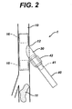
- Figure 2 is a plan view of another embodiment of a graft coupling device for end-to-side sutureless coupling of vessels according to the invention; and
- Figure 3 is a plan view of an embodiment of a coupling device for end-to-end sutureless coupling of vessels according to the invention.
-
- Like reference numbers indicate identical or functionally similar elements.
- Figure 1 depicts a presently preferred embodiment of a
graft coupling device 1 according to the invention for end-to-side anastamosis. As depicted in FIG.1,native vessel 10 has some disease orobstruction 11, requiring a bypass graft to preserve flow to some distal point in the vasculature. Such a situation is typical of femoral-femoral or femoral-politeal bypass procedures. As will be appreciated, in the case of end-to-side anastamosis, it is considered favorable to maintain flow distal to the site of graft attachment. In such a procedure,native vessel 10 will be accessed in an open procedure to allow a surgeon to make anincision 12 in side wall ofvessel 10. With direct access tovessel 10 available, the surgeon placesmain trunk 20 ofgraft coupling device 1 in theinterior 13 ofvessel 10. In placing thedevice 1, the surgeon allowsgraft extension 30 to protrude from theincision 12. - Proximal and distal
main trunk anchors main trunk 20 tonative vessel 10 proximally and distally to theincision 12 andgraft extension 30.Anchors trunk 20, or alternatively, may be deployed in a secondary step. - Preferably,
anchors main trunk 20 in place. Alternatively, exterior anchors which constrict radially or otherwise exert an inward force may be used. -
Bypass graft 40 is extended overcoupling graft extension 30. Preferably,graft extension 30 is sized such that its diameter approximates the inner diameter ofbypass graft 40. Aninternal graft anchor 41 withinbypass graft 40 exerts an outward force, while anexternal graft anchor 42 exerts and inward force. The opposing forces from these anchors secure the seal between thegraft extension 30 andbypass graft 40. Alternatively, only aninternal graft anchor 41 orexternal graft anchor 42 could be used. However, as will be appreciated by one of ordinary skill in the art, the opposing forces of using both anchors is preferably in sealing and ensuring the structural integrity of the device and its positioning is maintained. - The anchors according to the invention may be constructed of any suitable material and shaped in any suitable configuration. Preferably, the internal and external anchors exhibit stent-like characteristics. The internal and external stent-like anchors may both feature superelastic properties, or alternatively one or both may be plastically deformable.
- In the case of a plastically deforming internal stent coupled with a superelastic external stent, the sealing pressure could be adjusted by balloon dilation of the internal stent. As the internal stent is ratcheted up in diameter, it increases the diameter of the external superelastic stent, thereby increasing the inward force it exerts on the graft-to-vessel seal.
- In the case of a plastically deformable external stent, a similar effect may be achieved using a balloon internally to force expansion of the graft, vessel, and both anchor stents. Alternatively, the deformable external stent may be manually crimped or constrained in diameter to further reengage the superelastic internal stent, also thereby increasing sealing pressure.
- In the cases wherein both the external and internal anchors are superelastic, their diameters would be set such that they would engage each other over a range of diameters with predictable or predetermined resultant sealing pressure. As such, the memory diameter of the external anchor would be smaller than the anticipated outer diameter of the external graft or vessel (depending on the procedure), while the memory diameter of the internal anchor would be larger than the anticipated inner diameter of the internal graft or vessel.
- In an alternative exemplary embodiment for end-to-side anastamosis depicted in Figure 2, the roles of the
graft extension 30 andbypass graft 40 are reversed such that the graft extension is external and the bypass graft is internal. In accordance with this exemplary embodiment, the external stent-like anchor 42 could be integral with thegraft extension 30 as an exoskeleton. This exemplary embodiment offers the possibility of a less invasive procedure in that the device and coupling can be achieved without external access to the vessel or junction site. - In operation, access to the femoral artery 10 (or other target vessel) is achieved through normal means well known in the art of endovascular procedures. A guide wire (not shown) is delivered to the site at which the
bypass graft 40 is to join themain vessel 10. Once properly positioned, blood flow to the region is attenuated by some other endovascular means, for example, deployment of a balloon proximal to the site, preferably proximal to the wire access point. The desired junction site is deliberately punctured and dilated using endovascular techniques within the skill of the ordinary artisan. Thegraft coupling device 1, includingmain trunk 20,graft extension 30, andinternal anchors graft extension 30. - The primary guidewire remains in the main vessel, while the secondary guidewire is navigated to exit the
vessel 10 at the puncture site.Anchors main trunk 20 of thecoupling graft device 1 into themain vessel 10. Theexternal anchor exoskeleton 42 in this exemplary embodiment is preferably plastically deformable. Accordingly, at this point in the procedure, a balloon is advanced along the secondary guidewire to the location ofexternal anchor 42, and it is partially expanded to a diameter which allows it to accommodatebypass graft 40. -
Bypass graft 40 is preferably navigated to the attachment site using some endoscopic other minimally invasive technique. Preferably, the device used to advance the graft must have the capability to locate and snare the second guidewire which was punctured through the vessel as described above. Once the guidewire is successfully located, thebypass graft 40 may be advanced into the graft extension 30 (which has preferably been partially expanded as previously described).Internal anchor 41 may now be advanced along the secondary guidewire and deployed insidebypass graft 40. - A final balloon inflation inside the
internal anchor 41 fully expandsexternal anchor 42 and fully engages the internal and external anchors to provide an adequate seal. Accordingly, at this point the vessels have been joined together without external manual access to the junction site. Blood flow may be restored when the opposite end of the bypass graft is properly terminated. - Figure 3 depicts a presently preferred exemplary embodiment of the invention for end-to-end anastamosis. The device and procedure for end-to-end anastamosis according to this exemplary embodiment of the present invention is particularly preferred in cases where the bypass graft is a harvested vessel rather than an artificial graft. As depicted in FIG. 3, rather than insert one vessel inside another or suture their respective ends together, a straight tube-
like coupling graft 70 is provided for joining the vessels ends. Thiscoupling graft 70 is positioned inside of the two mating vessels. - As depicted,
main vessel 10 is to be coupled to bypass graft ordonor vessel 80. Accordingly,main vessel end 100 anddonor vessel end 101 are positioned overcoupling graft tube 70 and sealed in place withinternal anchors coupling graft tube 70 acts like an interior fluid coupling member, stent-anchor 142 which is positioned exterior of the mating vessels provides a force to provide fluid tight sealing from the exterior of the vessels. Preferably,tube 70 comprises a material suitable for use as an internal fluid carrying conduit and coupling device. - As will be appreciated, with this configuration of the present invention, neither
main vessel 10 nordonor vessel 80 has to be fit within the other or have theirrespective ends
Claims (16)
- A device for coupling vessels comprising:a main trunk;first and second stent-anchors associated with said main trunk;a graft extension extending from said main trunk;a bypass vessel;an internal anchor and an external anchor; said internal anchor and said external anchor cooperating to seal said graft extension and said bypass vessel.
- The device of claim 1 wherein said bypass vessel comprises an artificial graft or a donor vessel.
- The device of claim 2 wherein said bypass vessel extends over said graft extension and wherein said internal anchor is disposed in said graft extension in an area at least partially overlapped by said bypass vessel.
- The device of claim 3, wherein said external anchor is integral with said bypass vessel in an area which at least partially overlaps said bypass vessel.
- The device of claim 2 wherein said graft extension extends over said bypass vessel and wherein said internal anchor is disposed in said bypass vessel in an area at least partially overlapped by said graft extension.
- The device of claim 5 wherein said external anchor is integral with said graft extension in an area which at least partially overlaps said bypass vessel.
- The device of claim 1 wherein said first and second stent-anchors are disposed in an interior area of said main trunk on opposite ends of said graft extension.
- The device of claim 7 wherein said first and second stent-anchors exude an outward force to seal said main trunk in a main vessel.
- The device of claim 8 wherein said first and/or second stent-anchors comprise a plastically deformable material.
- A device for coupling vessels comprising:a main vessel having an end;a bypass vessel having an end;a coupling graft disposed within said main vessel end and said bypass vessel end;a main vessel internal stent-anchor configured to seal said main vessel with said coupling graft;a bypass vessel internal stent-anchor configured to seal said bypass vessel with said coupling graft; whereby said main vessel and said bypass vessel are held in fluid communication via said coupling graft.
- The device of claim 10, wherein said bypass vessel comprises a bypass graft or a donor vessel.
- The device of claim 11, further comprising an external anchor for sealing said main vessel end and said bypass vessel end around said coupling graft.
- The device of claim 12 wherein said main vessel internal stent-anchor and said bypass vessel internal stent-anchor exude an outward force to seal said coupling graft to said vessels.
- The device of claim 13 wherein said stent-anchors comprise a plastically deformable material.
- The device of claim 14 wherein said stent-anchors are ratchetable to increase a diameter of said stent-anchors.
- The device of claim 15 wherein said stent-anchors are ratchetable by balloon expansion.
Applications Claiming Priority (2)
| Application Number | Priority Date | Filing Date | Title |
|---|---|---|---|
| US10/685,374 US20050080482A1 (en) | 2003-10-14 | 2003-10-14 | Graft coupling apparatus and methods of using same |
| US685374 | 2003-10-14 |
Publications (2)
| Publication Number | Publication Date |
|---|---|
| EP1523958A1 true EP1523958A1 (en) | 2005-04-20 |
| EP1523958B1 EP1523958B1 (en) | 2012-08-01 |
Family
ID=34377620
Family Applications (1)
| Application Number | Title | Priority Date | Filing Date |
|---|---|---|---|
| EP04256298A Not-in-force EP1523958B1 (en) | 2003-10-14 | 2004-10-13 | Graft coupling apparatus and methods of using same |
Country Status (4)
| Country | Link |
|---|---|
| US (1) | US20050080482A1 (en) |
| EP (1) | EP1523958B1 (en) |
| JP (2) | JP2005131389A (en) |
| CA (1) | CA2484643C (en) |
Cited By (2)
| Publication number | Priority date | Publication date | Assignee | Title |
|---|---|---|---|---|
| EP1815822A2 (en) | 2006-02-01 | 2007-08-08 | Cordis Corporation | System of attaching vessels to grafts |
| WO2011043888A1 (en) | 2009-10-08 | 2011-04-14 | Circulite, Inc. | Two piece endovascular anastomotic connector |
Families Citing this family (11)
| Publication number | Priority date | Publication date | Assignee | Title |
|---|---|---|---|---|
| US7147661B2 (en) | 2001-12-20 | 2006-12-12 | Boston Scientific Santa Rosa Corp. | Radially expandable stent |
| US7361190B2 (en) * | 2004-06-29 | 2008-04-22 | Micardia Corporation | Adjustable cardiac valve implant with coupling mechanism |
| AU2006269444B2 (en) * | 2005-07-07 | 2011-07-21 | Cook Medical Technologies Llc | Branch vessel stent graft |
| CA2615535C (en) | 2005-07-27 | 2013-12-24 | Cook Critical Care Incorporated | Stent/graft device and method for open surgical placement |
| US20080294235A1 (en) * | 2007-05-24 | 2008-11-27 | Inverthis Ltd. | Bypass graft device and delivery system and method |
| WO2009055574A2 (en) | 2007-10-26 | 2009-04-30 | Cook Critical Care Incorporated | Vascular conduit and delivery system for open surgical placement |
| WO2009102439A1 (en) * | 2008-02-11 | 2009-08-20 | William Cook Europe Aps | Prosthesis coupling device and method |
| JP5544597B2 (en) * | 2009-11-27 | 2014-07-09 | 川澄化学工業株式会社 | Tubular tissue anastomosis instrument |
| JP5548981B2 (en) * | 2009-11-27 | 2014-07-16 | 川澄化学工業株式会社 | Tubular tissue anastomosis instrument |
| EP2524711B1 (en) * | 2011-05-16 | 2014-01-08 | Berlin Heart GmbH | Connection system for producing a connection channel for bodily fluids |
| DE102016120445A1 (en) * | 2016-10-26 | 2018-04-26 | Manemed Ingenieurbüro für Medizintechnik | double stent |
Citations (5)
| Publication number | Priority date | Publication date | Assignee | Title |
|---|---|---|---|---|
| US5984955A (en) * | 1997-09-11 | 1999-11-16 | Wisselink; Willem | System and method for endoluminal grafting of bifurcated or branched vessels |
| US20020099441A1 (en) * | 1999-12-29 | 2002-07-25 | Edwards Lifesciences, Llc | Towel graft means for enhancing tissue ingrowth in vascular grafts |
| US20020173808A1 (en) * | 1998-06-10 | 2002-11-21 | Russell A. Houser | Sutureless anastomosis systems |
| US20040073282A1 (en) * | 2001-08-06 | 2004-04-15 | Paul Stanish | Distally-narrowed vascular grafts and methods of using same for making artery-to-vein and artery-to-artery connections |
| US20040116945A1 (en) * | 2000-04-29 | 2004-06-17 | Ventrica, Inc., A Delaware Corporation | Components, systems and methods for forming anastomoses using magnetism or other coupling means |
Family Cites Families (12)
| Publication number | Priority date | Publication date | Assignee | Title |
|---|---|---|---|---|
| JPS6031743A (en) * | 1983-07-29 | 1985-02-18 | 日本ゼオン株式会社 | Blood bypassing tube |
| NL1009028C2 (en) * | 1998-04-28 | 1999-10-29 | Adri Marinus Blomme | Adhesives for connecting a tubular vascular prosthesis to a blood vessel in the body as well as branching means, a vascular prosthesis, a device for inserting and adhering a vascular prosthesis and a vascular prosthesis system. |
| IL149474A0 (en) * | 1999-11-05 | 2002-11-10 | Onux Medical Inc | Apparatus and method for placing multiple sutures during anastomosis |
| JP2004534552A (en) * | 2000-08-10 | 2004-11-18 | ダイアリシス・アクセス・ソルーションズ・インコーポレーテッド | Distally narrowed vascular graft and method of using the same to make arterial-to-venous and arterial-to-arterial connections |
| JP2004508884A (en) * | 2000-09-25 | 2004-03-25 | コヒージョン テクノロジーズ, インコーポレイテッド | Resorbable anastomotic stent and plug |
| JP3686833B2 (en) * | 2000-11-28 | 2005-08-24 | 壮介 木村 | Vascular anastomosis ring and artificial blood vessel equipped with vascular anastomosis ring |
| AU2002236790B2 (en) * | 2001-01-19 | 2006-08-17 | Boston Scientific Limited | Introducer for deployment of branched prosthesis |
| JP2002301083A (en) * | 2001-04-09 | 2002-10-15 | Nec Tokin Corp | Blood vessel anastomic device |
| FR2827502B1 (en) * | 2001-07-17 | 2004-04-09 | Univ Joseph Fourier | MICROMUSCLE IN A BIOLOGICAL ENVIRONMENT |
| JP2003290233A (en) * | 2002-04-02 | 2003-10-14 | Nippon Cable Syst Inc | Guide shaft for coupling tubular organs |
| DK1545396T3 (en) * | 2002-08-23 | 2009-03-02 | Cook William A Australia | composite prosthesis |
| EP1610720B1 (en) * | 2003-03-28 | 2009-02-18 | GI Dynamics, Inc. | Anti-obesity devices |
-
2003
- 2003-10-14 US US10/685,374 patent/US20050080482A1/en not_active Abandoned
-
2004
- 2004-10-13 EP EP04256298A patent/EP1523958B1/en not_active Not-in-force
- 2004-10-13 JP JP2004299123A patent/JP2005131389A/en active Pending
- 2004-10-13 CA CA002484643A patent/CA2484643C/en not_active Expired - Fee Related
-
2011
- 2011-04-07 JP JP2011085115A patent/JP5329594B2/en active Active
Patent Citations (5)
| Publication number | Priority date | Publication date | Assignee | Title |
|---|---|---|---|---|
| US5984955A (en) * | 1997-09-11 | 1999-11-16 | Wisselink; Willem | System and method for endoluminal grafting of bifurcated or branched vessels |
| US20020173808A1 (en) * | 1998-06-10 | 2002-11-21 | Russell A. Houser | Sutureless anastomosis systems |
| US20020099441A1 (en) * | 1999-12-29 | 2002-07-25 | Edwards Lifesciences, Llc | Towel graft means for enhancing tissue ingrowth in vascular grafts |
| US20040116945A1 (en) * | 2000-04-29 | 2004-06-17 | Ventrica, Inc., A Delaware Corporation | Components, systems and methods for forming anastomoses using magnetism or other coupling means |
| US20040073282A1 (en) * | 2001-08-06 | 2004-04-15 | Paul Stanish | Distally-narrowed vascular grafts and methods of using same for making artery-to-vein and artery-to-artery connections |
Cited By (6)
| Publication number | Priority date | Publication date | Assignee | Title |
|---|---|---|---|---|
| EP1815822A2 (en) | 2006-02-01 | 2007-08-08 | Cordis Corporation | System of attaching vessels to grafts |
| EP1815822A3 (en) * | 2006-02-01 | 2007-11-07 | Cordis Corporation | System of attaching vessels to grafts |
| EP2127615A2 (en) * | 2006-02-01 | 2009-12-02 | Cordis Corporation | System of Attaching Vessels to Grafts |
| EP2127615A3 (en) * | 2006-02-01 | 2010-05-19 | Cordis Corporation | System of Attaching Vessels to Grafts |
| WO2011043888A1 (en) | 2009-10-08 | 2011-04-14 | Circulite, Inc. | Two piece endovascular anastomotic connector |
| EP2485785A4 (en) * | 2009-10-08 | 2017-12-06 | CircuLite, Inc. | Two piece endovascular anastomotic connector |
Also Published As
| Publication number | Publication date |
|---|---|
| CA2484643C (en) | 2010-01-05 |
| JP2005131389A (en) | 2005-05-26 |
| US20050080482A1 (en) | 2005-04-14 |
| JP5329594B2 (en) | 2013-10-30 |
| CA2484643A1 (en) | 2005-04-14 |
| EP1523958B1 (en) | 2012-08-01 |
| JP2011156377A (en) | 2011-08-18 |
Similar Documents
| Publication | Publication Date | Title |
|---|---|---|
| JP5329594B2 (en) | Device for joining vessels | |
| US6533812B2 (en) | Medical anastomosis apparatus | |
| AU2008243229B2 (en) | Endovascular aneurysm repair system | |
| US7303569B2 (en) | Implantable superelastic anastomosis device | |
| US20030109887A1 (en) | Medical graft component and methods of installing same | |
| US5728131A (en) | Coupling device and method of use | |
| EP2127615A2 (en) | System of Attaching Vessels to Grafts | |
| US8109947B2 (en) | Medical grafting methods and apparatus | |
| EP2651314B1 (en) | Systems for bypassing an anastomosis site | |
| US20110118763A1 (en) | Method and apparatus for effecting an aortic valve bypass, including the provision and use of a t-stent for effecting a distal anastomosis for the same | |
| US11413043B2 (en) | Anchor device for vascular anastomosis | |
| TW202241363A (en) | Vascular and aortic grafts and deployment tool | |
| JP2005131389A5 (en) | ||
| US20030130671A1 (en) | Anastomosis device and method | |
| US20040044349A1 (en) | Anastomosis device delivery systems | |
| US20050137610A1 (en) | Facilitating catheter assembly |
Legal Events
| Date | Code | Title | Description |
|---|---|---|---|
| PUAI | Public reference made under article 153(3) epc to a published international application that has entered the european phase |
Free format text: ORIGINAL CODE: 0009012 |
|
| AK | Designated contracting states |
Kind code of ref document: A1 Designated state(s): AT BE BG CH CY CZ DE DK EE ES FI FR GB GR HU IE IT LI LU MC NL PL PT RO SE SI SK TR |
|
| AX | Request for extension of the european patent |
Extension state: AL HR LT LV MK |
|
| 17P | Request for examination filed |
Effective date: 20050523 |
|
| AKX | Designation fees paid |
Designated state(s): AT BE BG CH CY CZ DE DK EE ES FI FR GB GR HU IE IT LI LU MC NL PL PT RO SE SI SK TR |
|
| GRAP | Despatch of communication of intention to grant a patent |
Free format text: ORIGINAL CODE: EPIDOSNIGR1 |
|
| GRAS | Grant fee paid |
Free format text: ORIGINAL CODE: EPIDOSNIGR3 |
|
| GRAA | (expected) grant |
Free format text: ORIGINAL CODE: 0009210 |
|
| AK | Designated contracting states |
Kind code of ref document: B1 Designated state(s): AT BE BG CH CY CZ DE DK EE ES FI FR GB GR HU IE IT LI LU MC NL PL PT RO SE SI SK TR |
|
| REG | Reference to a national code |
Ref country code: GB Ref legal event code: FG4D |
|
| REG | Reference to a national code |
Ref country code: CH Ref legal event code: EP Ref country code: AT Ref legal event code: REF Ref document number: 568222 Country of ref document: AT Kind code of ref document: T Effective date: 20120815 |
|
| REG | Reference to a national code |
Ref country code: IE Ref legal event code: FG4D |
|
| REG | Reference to a national code |
Ref country code: DE Ref legal event code: R096 Ref document number: 602004038711 Country of ref document: DE Effective date: 20121011 |
|
| REG | Reference to a national code |
Ref country code: NL Ref legal event code: T3 |
|
| REG | Reference to a national code |
Ref country code: AT Ref legal event code: MK05 Ref document number: 568222 Country of ref document: AT Kind code of ref document: T Effective date: 20120801 |
|
| PG25 | Lapsed in a contracting state [announced via postgrant information from national office to epo] |
Ref country code: CY Free format text: LAPSE BECAUSE OF FAILURE TO SUBMIT A TRANSLATION OF THE DESCRIPTION OR TO PAY THE FEE WITHIN THE PRESCRIBED TIME-LIMIT Effective date: 20120801 Ref country code: FI Free format text: LAPSE BECAUSE OF FAILURE TO SUBMIT A TRANSLATION OF THE DESCRIPTION OR TO PAY THE FEE WITHIN THE PRESCRIBED TIME-LIMIT Effective date: 20120801 Ref country code: AT Free format text: LAPSE BECAUSE OF FAILURE TO SUBMIT A TRANSLATION OF THE DESCRIPTION OR TO PAY THE FEE WITHIN THE PRESCRIBED TIME-LIMIT Effective date: 20120801 |
|
| PG25 | Lapsed in a contracting state [announced via postgrant information from national office to epo] |
Ref country code: PT Free format text: LAPSE BECAUSE OF FAILURE TO SUBMIT A TRANSLATION OF THE DESCRIPTION OR TO PAY THE FEE WITHIN THE PRESCRIBED TIME-LIMIT Effective date: 20121203 Ref country code: PL Free format text: LAPSE BECAUSE OF FAILURE TO SUBMIT A TRANSLATION OF THE DESCRIPTION OR TO PAY THE FEE WITHIN THE PRESCRIBED TIME-LIMIT Effective date: 20120801 Ref country code: SE Free format text: LAPSE BECAUSE OF FAILURE TO SUBMIT A TRANSLATION OF THE DESCRIPTION OR TO PAY THE FEE WITHIN THE PRESCRIBED TIME-LIMIT Effective date: 20120801 Ref country code: SI Free format text: LAPSE BECAUSE OF FAILURE TO SUBMIT A TRANSLATION OF THE DESCRIPTION OR TO PAY THE FEE WITHIN THE PRESCRIBED TIME-LIMIT Effective date: 20120801 Ref country code: GR Free format text: LAPSE BECAUSE OF FAILURE TO SUBMIT A TRANSLATION OF THE DESCRIPTION OR TO PAY THE FEE WITHIN THE PRESCRIBED TIME-LIMIT Effective date: 20121102 |
|
| PG25 | Lapsed in a contracting state [announced via postgrant information from national office to epo] |
Ref country code: CZ Free format text: LAPSE BECAUSE OF FAILURE TO SUBMIT A TRANSLATION OF THE DESCRIPTION OR TO PAY THE FEE WITHIN THE PRESCRIBED TIME-LIMIT Effective date: 20120801 Ref country code: RO Free format text: LAPSE BECAUSE OF FAILURE TO SUBMIT A TRANSLATION OF THE DESCRIPTION OR TO PAY THE FEE WITHIN THE PRESCRIBED TIME-LIMIT Effective date: 20120801 Ref country code: ES Free format text: LAPSE BECAUSE OF FAILURE TO SUBMIT A TRANSLATION OF THE DESCRIPTION OR TO PAY THE FEE WITHIN THE PRESCRIBED TIME-LIMIT Effective date: 20121112 Ref country code: DK Free format text: LAPSE BECAUSE OF FAILURE TO SUBMIT A TRANSLATION OF THE DESCRIPTION OR TO PAY THE FEE WITHIN THE PRESCRIBED TIME-LIMIT Effective date: 20120801 Ref country code: EE Free format text: LAPSE BECAUSE OF FAILURE TO SUBMIT A TRANSLATION OF THE DESCRIPTION OR TO PAY THE FEE WITHIN THE PRESCRIBED TIME-LIMIT Effective date: 20120801 |
|
| PG25 | Lapsed in a contracting state [announced via postgrant information from national office to epo] |
Ref country code: SK Free format text: LAPSE BECAUSE OF FAILURE TO SUBMIT A TRANSLATION OF THE DESCRIPTION OR TO PAY THE FEE WITHIN THE PRESCRIBED TIME-LIMIT Effective date: 20120801 Ref country code: MC Free format text: LAPSE BECAUSE OF NON-PAYMENT OF DUE FEES Effective date: 20121031 |
|
| REG | Reference to a national code |
Ref country code: CH Ref legal event code: PL |
|
| PLBE | No opposition filed within time limit |
Free format text: ORIGINAL CODE: 0009261 |
|
| STAA | Information on the status of an ep patent application or granted ep patent |
Free format text: STATUS: NO OPPOSITION FILED WITHIN TIME LIMIT |
|
| 26N | No opposition filed |
Effective date: 20130503 |
|
| PG25 | Lapsed in a contracting state [announced via postgrant information from national office to epo] |
Ref country code: CH Free format text: LAPSE BECAUSE OF NON-PAYMENT OF DUE FEES Effective date: 20121031 Ref country code: BG Free format text: LAPSE BECAUSE OF FAILURE TO SUBMIT A TRANSLATION OF THE DESCRIPTION OR TO PAY THE FEE WITHIN THE PRESCRIBED TIME-LIMIT Effective date: 20121101 Ref country code: LI Free format text: LAPSE BECAUSE OF NON-PAYMENT OF DUE FEES Effective date: 20121031 |
|
| REG | Reference to a national code |
Ref country code: DE Ref legal event code: R097 Ref document number: 602004038711 Country of ref document: DE Effective date: 20130503 |
|
| PG25 | Lapsed in a contracting state [announced via postgrant information from national office to epo] |
Ref country code: TR Free format text: LAPSE BECAUSE OF FAILURE TO SUBMIT A TRANSLATION OF THE DESCRIPTION OR TO PAY THE FEE WITHIN THE PRESCRIBED TIME-LIMIT Effective date: 20120801 |
|
| PG25 | Lapsed in a contracting state [announced via postgrant information from national office to epo] |
Ref country code: LU Free format text: LAPSE BECAUSE OF NON-PAYMENT OF DUE FEES Effective date: 20121013 |
|
| PG25 | Lapsed in a contracting state [announced via postgrant information from national office to epo] |
Ref country code: HU Free format text: LAPSE BECAUSE OF FAILURE TO SUBMIT A TRANSLATION OF THE DESCRIPTION OR TO PAY THE FEE WITHIN THE PRESCRIBED TIME-LIMIT Effective date: 20041013 |
|
| REG | Reference to a national code |
Ref country code: FR Ref legal event code: PLFP Year of fee payment: 13 |
|
| REG | Reference to a national code |
Ref country code: FR Ref legal event code: PLFP Year of fee payment: 14 |
|
| PGFP | Annual fee paid to national office [announced via postgrant information from national office to epo] |
Ref country code: DE Payment date: 20171027 Year of fee payment: 14 Ref country code: FR Payment date: 20171025 Year of fee payment: 14 |
|
| PGFP | Annual fee paid to national office [announced via postgrant information from national office to epo] |
Ref country code: BE Payment date: 20171027 Year of fee payment: 14 Ref country code: NL Payment date: 20171026 Year of fee payment: 14 Ref country code: IE Payment date: 20171031 Year of fee payment: 14 Ref country code: IT Payment date: 20171024 Year of fee payment: 14 Ref country code: GB Payment date: 20171027 Year of fee payment: 14 |
|
| REG | Reference to a national code |
Ref country code: GB Ref legal event code: 732E Free format text: REGISTERED BETWEEN 20180614 AND 20180620 |
|
| REG | Reference to a national code |
Ref country code: DE Ref legal event code: R119 Ref document number: 602004038711 Country of ref document: DE |
|
| REG | Reference to a national code |
Ref country code: NL Ref legal event code: MM Effective date: 20181101 |
|
| GBPC | Gb: european patent ceased through non-payment of renewal fee |
Effective date: 20181013 |
|
| REG | Reference to a national code |
Ref country code: BE Ref legal event code: MM Effective date: 20181031 |
|
| REG | Reference to a national code |
Ref country code: IE Ref legal event code: MM4A |
|
| PG25 | Lapsed in a contracting state [announced via postgrant information from national office to epo] |
Ref country code: DE Free format text: LAPSE BECAUSE OF NON-PAYMENT OF DUE FEES Effective date: 20190501 Ref country code: NL Free format text: LAPSE BECAUSE OF NON-PAYMENT OF DUE FEES Effective date: 20181101 |
|
| REG | Reference to a national code |
Ref country code: DE Ref legal event code: R082 Ref document number: 602004038711 Country of ref document: DE Representative=s name: BOEHMERT & BOEHMERT ANWALTSPARTNERSCHAFT MBB -, DE |
|
| PG25 | Lapsed in a contracting state [announced via postgrant information from national office to epo] |
Ref country code: FR Free format text: LAPSE BECAUSE OF NON-PAYMENT OF DUE FEES Effective date: 20181031 Ref country code: BE Free format text: LAPSE BECAUSE OF NON-PAYMENT OF DUE FEES Effective date: 20181031 |
|
| PG25 | Lapsed in a contracting state [announced via postgrant information from national office to epo] |
Ref country code: IT Free format text: LAPSE BECAUSE OF NON-PAYMENT OF DUE FEES Effective date: 20181013 Ref country code: GB Free format text: LAPSE BECAUSE OF NON-PAYMENT OF DUE FEES Effective date: 20181013 Ref country code: IE Free format text: LAPSE BECAUSE OF NON-PAYMENT OF DUE FEES Effective date: 20181013 |