EP1523919A1 - Holder and cleaning implement using the holder - Google Patents
Holder and cleaning implement using the holder Download PDFInfo
- Publication number
- EP1523919A1 EP1523919A1 EP03741481A EP03741481A EP1523919A1 EP 1523919 A1 EP1523919 A1 EP 1523919A1 EP 03741481 A EP03741481 A EP 03741481A EP 03741481 A EP03741481 A EP 03741481A EP 1523919 A1 EP1523919 A1 EP 1523919A1
- Authority
- EP
- European Patent Office
- Prior art keywords
- handle
- support member
- cleaning
- locking member
- locking
- Prior art date
- Legal status (The legal status is an assumption and is not a legal conclusion. Google has not performed a legal analysis and makes no representation as to the accuracy of the status listed.)
- Granted
Links
Images


Classifications
-
- A—HUMAN NECESSITIES
- A47—FURNITURE; DOMESTIC ARTICLES OR APPLIANCES; COFFEE MILLS; SPICE MILLS; SUCTION CLEANERS IN GENERAL
- A47L—DOMESTIC WASHING OR CLEANING; SUCTION CLEANERS IN GENERAL
- A47L13/00—Implements for cleaning floors, carpets, furniture, walls, or wall coverings
- A47L13/10—Scrubbing; Scouring; Cleaning; Polishing
- A47L13/38—Other dusting implements
-
- A—HUMAN NECESSITIES
- A47—FURNITURE; DOMESTIC ARTICLES OR APPLIANCES; COFFEE MILLS; SPICE MILLS; SUCTION CLEANERS IN GENERAL
- A47L—DOMESTIC WASHING OR CLEANING; SUCTION CLEANERS IN GENERAL
- A47L13/00—Implements for cleaning floors, carpets, furniture, walls, or wall coverings
- A47L13/10—Scrubbing; Scouring; Cleaning; Polishing
- A47L13/20—Mops
- A47L13/24—Frames for mops; Mop heads
- A47L13/254—Plate frames
- A47L13/256—Plate frames for mops made of cloth
-
- B—PERFORMING OPERATIONS; TRANSPORTING
- B25—HAND TOOLS; PORTABLE POWER-DRIVEN TOOLS; MANIPULATORS
- B25G—HANDLES FOR HAND IMPLEMENTS
- B25G1/00—Handle constructions
- B25G1/06—Handle constructions reversible or adjustable for position
Definitions
- the present invention relates to a device for holding a disposable or reusable cleaning wiper and a cleaning tool constructed of the holding device and the cleaning wiper.
- Japanese Unexamined Patent Publication Nos. 9-154791 and 9-38009 disclose cleaning tools for holding a cleaning cloth comprising nonwoven fabric and the like, in which a head for supporting the cleaning cloth is provided at a front end of a short handle or axially extendable handle that can be held with one hand.
- the head disclosed in the above-mentioned Patent Publications is fixed in position so as not to move at the front end of the handle, the handle held with hand for cleaning a surface to be cleaned with the cleaning cloth attached to the head need be turned in various directions in accordance with the shape of the surface to be cleaned. Therefore, it is not suitable for cleaning a variously oriented surface to be cleaned such as furniture surface.
- Japanese Unexamined Patent Publication Nos. 51-85273 and 2002-17640 disclose cleaning tools in which a brush-like cleaning device is attached to a front end of a handle so as to be adjustable in position.
- the brush-like cleaning device used for these cleaning tools is pivotally attached to the front end of the handle.
- a plurality of recesses are formed in an outer periphery of a rotary portion that rotates together with the cleaning device, while a locking member for fitting in the recesses are provided in the handle, so that the position of the brush-like cleaning device can be changed and fixed by fitting the locking member in the recesses.
- the locking member cannot enter the recess if the rotary ring is turned or the operating part is pushed forward by hand before the locking member is exactly confronted by the recess, so that the locking member sometimes fails in fitting into the recess. Accordingly, the operation of the rotary ring or the operating part must be done after the locking member is confronted by the recess, so that it tends to take much time to certainly fix the cleaning device in position.
- the cleaning devices disclosed in the two Patent Publications still moreover, although the position of the brush-like cleaning device can be changed within a predetermined angular range, the cleaning device cannot be folded back to overlie the handle. That is, the cleaning tools disclosed in the two Patent Publications are not intended to support a disposable cleaning wiper, but the brush-like cleaning device for a long time use is attached to the handle. Therefore, the holding device is intended to be left attached even when it is not used, not assuming such a usage that the cleaning tool is folded back for storage with a wiper removed therefrom, unlike a cleaning tool to which a disposable wiper is intended to be attached.
- the present invention has been worked out in view of the shortcomings in the prior art set forth above. It is therefore an object of the present invention to provide a holding device, wherein the position of a support member to which a cleaning wiper is to be attached can be changed with a simple operation and the support member can be stabilized in predetermined positions without causing unexpected turn, and a cleaning tool with the holding device.
- a holding device for a cleaning wiper comprising:
- the locking member can be released from the recesses by moving the locking member away from the recesses against the biasing force of the biasing member, thereby permitting the support member to turn. Thereafter, when the operating force to the locking member is eliminated, the locking member moves along the axis of the handle due to the biasing force, whereby the locking member fits in one recess so that the support member goes to an engaged and fixed state (locked state).
- the locking member can automatically fit in the recess due to the biasing force so that the support member goes to the engaged and fixed state. That is, when the position of the support member is to be changed, the support member can automatically go to the engaged and fixed state such that the locking member is moved away from the recess by operation of the operating member, the operating member is let go of during a turn of the support member, and then the support member is turned only a little more.
- the operation for changing the position of the support member is quite simple.
- the locking member since the locking member is so provided axially movably inside the handle as to fit in the recess of the support member, the locking member can be made thick as well as the support member can be made wide at its portion having the recesses. Accordingly, the locking strength when the locking member fits in the recess can be increased.
- the handle can be made thin when the locking member is provided axially movably.
- the pivot connection between the handle and the support member can be of a simple construction and the radius from the pivot axis to the sliding surfaces can be made large to increase the fixing strength when the locking member is engaged with and fixed to the recess. Accordingly, when the support member goes to the engaged and fixed state, the position of the support member can be stabilized so as not to cause unexpected change.
- the present invention may be constructed such that the sliding surfaces are formed on an imaginary cylindrical surface with center at the pivot axis.
- the sliding surfaces are part of the cylindrical surface, when the support member is turned with the locking member in contact with the sliding surface, the locking member can smoothly slide on the sliding surface to fit into the recess.
- the sliding surfaces located between adjacent recesses may be flat surfaces extending in a direction tangential to an imaginary circle with center at the pivot axis.
- the present invention may be constructed such that the support member has a cleaning support surface for pressing a cleaning wiper attached thereto against a surface to be cleaned, wherein selective engagement of the locking member in the recesses permits a stepwise change of angle between the shaft axis and the cleaning support surface.
- the handle With the stepwise change of the angle of the cleaning support surface for pressing the cleaning wiper against a surface to be cleaned, the handle can be held with hand always in suitable positions for cleaning operation, so that an object such as furniture having variously oriented surfaces to be cleaned, ceiling, and the like can be easily cleaned.
- one of the recesses is a fold locking recess and when the locking member engages in the fold locking recess, the support member is folded back to substantially overlie the handle.
- the support member when the holding device is not used, the support member can be folded back to substantially overlie the handle with the cleaning wiper removed from the support member, for instance, so that a large storage space is not required.
- the present invention may be constructed such that the operating member is a push button that is externally exposed on an outer periphery of the handle and movable in a direction crossing the shaft axis, and at least one of the push button and the locking member has an inclined sliding surface inclined to both a direction along which the push button is to be pushed and a direction along which the locking member is movable, wherein a sliding component force acting on the inclined sliding surface as the push button is pushed permits the locking member to move against the biasing force of the biasing member.
- the handle can be made thin, as set forth above.
- the push button is provided to be movable in a direction crossing the shaft axis of the handle, the operation for releasing the engagement and fixation (lock) between the locking member and the recess can be performed quite easily.
- the present invention may be constructed such that the operating member is a sliding button that is externally exposed on an outer periphery of the handle and movable along the shaft axis, wherein the sliding button permits the locking member to move against the biasing force of the biasing member.
- the sliding button is thus provided to be movable axially of the handle, the inner structure of the handle can be made simple, and even if the handle is made thin, the locking member can be certainly operated.
- a cleaning tool comprising: the foregoing holding device; and a cleaning wiper to be attached to the support member, wherein the cleaning wiper is a disposable wiper comprising nonwoven fabric, paper or a combination of nonwoven fabric and a bundle of fibers, and the cleaning wiper is supported by the support member with the support member inserted into holding spaces formed in the cleaning wiper.
- the cleaning wiper can be made soft, it can easily be attached to the support member or replaced.
- Figs. 1A, 1B and 1C are general side views showing a holding device according to a first embodiment of the present invention, wherein Fig. 1A shows a state where a cleaning support surface of a support member is oriented parallel with a shaft axis of a handle, Fig. 1B shows a state where the cleaning support surface is oriented perpendicular to the shaft axis of the handle, and Fig. 1C shows a state where the support member is folded back to substantially overlie the handle.
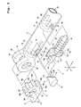
- Fig. 2 is a perspective view showing a structure of the support member and a cleaning wiper to be attached to the support member;
- Fig. 3 is an exploded perspective view showing a pivot connection between the handle and the support member and a locking mechanism;
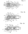
- Fig. 4 is a sectional view taken along an XY-plane, showing the pivot connection and the locking mechanism;
- Figs 5A and 5B and Figs. 6A and 6B are sectional views taken along a YZ-plane, showing the support member in different positions.
- a holding device 1 has a handle 2 and a housing handle 3.
- the handle 2 is illustrated as projecting forwardly from the housing handle 3, but the handle 2 can be retracted into the housing handle 3 so as to decrease the length of the assembly of the handle 2 and the housing handle 3.
- the housing handle 3 may be a telescopic handle so as to increase the length of the assembly of the handle 2 and the housing handle 3.
- the handle 2 is a cylinder of a hollow circular cross-section.
- the housing handle 3 is also a cylinder of a hollow circular cross-section. Referring to Fig. 1A, the shaft axis of the handle 2 and the housing handle 3 is indicated by Os.
- a support member 4 is pivotally connected to the front end of the handle 2 through a pivot connection 5.
- the pivot axis of the support member 4 at the pivot connection 5 is indicated by Or.
- the pivot axis Or is oriented in a direction perpendicularly intersecting the shaft axis Os of the handle 2.
- the support member 4 is pivotable about the pivot axis Or, and after the support member 4 is turned to respective positions, the support member 4 can be engaged and fixed (locked) by a locking mechanism 6 provided inside the handle 2.
- the lower surface of the support member 4 is a cleaning support surface 4a for pressing a cleaning wiper 8 attached to the support member 4 against a surface to be cleaned.
- the support member 4 can be engaged and fixed at five different positions.
- Fig. 1A shows a first cleaning position (i), in which the cleaning support surface 4a of the support member 4 is substantially parallel with the shaft axis Os of the handle 2, a second cleaning position (ii), in which the cleaning support surface 4a is turned by ⁇ 1 downwardly from the first cleaning position (i), and a third cleaning position (iii), in which the cleaning support surface 4a is turned by ⁇ 1 upwardly from the first cleaning position (i).
- Fig. 1B shows a fourth cleaning position (iv), in which the cleaning support surface 4a is further turned by ⁇ 1 upwardly from the third cleaning position (iii), and at this time, the cleaning support surface 4a becomes substantially perpendicular to the shaft axis Os.
- the support member 4 is further turned clockwise by ⁇ 2 from the fourth cleaning position (iv) of Fig. 1B, the support member 4 thus folded back overlies the handle 2 to take a folded position (v), wherein the cleaning support surface 4a faces upward and becomes substantially parallel with the shaft axis Os.
- the pivot angles ⁇ 1 of the support member 4 between adjacent cleaning positions are equal, while the pivot angel ⁇ 2 of the support member 4 from the fourth cleaning position (iv) to the folded position (v) is set larger than the pivot angles ⁇ 1 between adjacent cleaning positions. For instance, ⁇ 1 is 45 degrees, and ⁇ 2 is 90 degrees.
- a push button 70 as operating member for releasing the engagement and fixation (lock) through the locking mechanism 6, wherein the push button 70 projects outwardly beyond the outer periphery of the handle 2.
- the push button 70 is so positioned as not to interfere with the operation of the support member 4 in the folded position (v).
- Individual components constituting the handle 2, the housing handle 3, the support member 4, the pivot connection 5 and the locking mechanism 6 are all made of synthetic resin, such as ABS, vinyl chloride, PE (polyethylene), PP (polypropylene) and PET (polyethylene terephthalate), except for coil spring.
- synthetic resin such as ABS, vinyl chloride, PE (polyethylene), PP (polypropylene) and PET (polyethylene terephthalate), except for coil spring.
- the support body 4 has an arm 14 extending forwardly from the pivot connection 5, and the arm 14 is bifurcated to provide support strips 11, 11 in the form of parallel flat plates.
- the arm 14 is bifurcated to provide support strips 11, 11 in the form of parallel flat plates.
- two thin deformable projections 12, 12 are integrally formed.
- a clip 13 is integrally formed to extend forwardly between the support strips 11, 11.
- the lower surfaces of the support strips 11, 11 are regarded as the cleaning support surface 4a.
- the cleaning wiper 8 of Fig. 2 is a disposable, soft wiper, of which a main body 21 comprises a nonwoven fabric, a stack of nonwoven fabrics, a stack of papers, a foamed resin material, a stack of a nonwoven fabric and a bundle of fibers that is referred to as tow, or the like.
- a holding sheet 22 that comprises a nonwoven fabric or the like.
- the main body 21 and the holding sheet 22 are joined together at a pair of longitudinally extending side bond lines 23, 23 and a center bond line 24 extending parallel with and between the two side bond lines 23, 23.
- holding spaces 25, 25 Between the main body 21 and the holding sheet 22, there are formed holding spaces 25, 25 individually defined between one side bond line 23 and the center bond line 24.
- the individual holding spaces 25 have openings 25a, 25a on longitudinally opposite sides of the main body 21.
- the main body 21 of the cleaning wiper 8 beneath the cleaning support surface 4a i.e., the lower surfaces of the support strips 11, 11
- a surface to be cleaned such as floor and furniture.
- a washable (reusable) cleaning wiper may be attached to the support member 4, in place of the disposable wiper.
- the support member 4 is integrally formed, at its rear end of the arm 14, with a generally disc-shaped rotary portion 31, and a shaft hole 32 is formed to passes through the rotary portion 31 in the X-direction.
- the handle 2 is integrally formed, at its front end, with a pair of disc-shaped support portions 33, 33 to have a support space 34 between the support portions 33, 33. Support holes 35, 35 are formed to pass through the support portions 33, 33 in the X-direction.
- the thickness of the rotary portion 31 formed in the support member 4 is substantially equal to the width of the support space 34, so that the rotary portion 31 can be inserted into the support space 34 substantially without play.
- a first support shaft 36a is inserted into the support hole 35 from outside one support portion 33, while a second support shaft 36b is inserted into the support hole 35 from outside the other support portion 33.
- the first and second support shafts 36a, 36b are then inserted into the shaft hole 32 of the rotary portion 31 to fit each other within the shaft hole 32, wherein the first and second support shafts 36a, 36b may be bonded and fixed to each other, if desired.
- the shaft axis of the first and second support shafts 36a, 36b is the pivot axis Or.
- the pivot axis Or is oriented in a direction perpendicularly intersecting the shaft axis Os of the handle 2.
- the rotary portion 31, being integral with the support member 4 has first, second third and fourth recesses 38a, 38b, 38c and 38d formed in circumferentially spaced relation toward the pivot axis Or.
- the individual recesses 38a, 38b, 38c and 38d are formed linearly along the X-direction (direction parallel with the pivot axis Or) at a constant width.
- adjacent recesses i.e., the first and second recesses 38a and 38b, the first and third recesses 38a and 38c, and the third and fourth recesses 38c and 38d
- ⁇ 1 is 45 degrees, for instance.
- a fold locking recess 38e is provided at a position spaced counterclockwise apart from the fourth recess 38d by ⁇ 2.
- the ⁇ 2 is 90 degrees, for instance.
- a first sliding surface 39a is provided between the first and second recesses 38a and 38b
- a second sliding surface 39b is provided between the first and third recesses 38a and 38c
- a third sliding surface 39c is provided between the third and fourth recesses 38c and 38d.
- a fold sliding surface 39d is provided between the fourth recesses 38d and the fold locking recess 38e.
- the individual sliding surfaces 39a, 39b, 39c and 39d are formed on an imaginary cylindrical surface with radius R and center at the pivot axis Or.
- the rotary portion 31 of the support member 4 is held between the support portions 33 and 33 provided at the front end of the handle 2, not only the width but also the radius R of the rotary portion 31 can be made relatively large, so that the strength of engagement and fixation (locking strength) at the time when a locking projection 53 (which will be described later in detail) fits in the recess can be increased.
- the handle 2 is a cylinder having a mechanism housing space 2a inside of it.
- a partition 41 is integrally formed to separate the mechanism housing space 2a, at its front side adjacent the support portions 33, from the support space 34, and a rectangular window 42 is formed to pass through the partition 41 axially of the handle 2 (i.e., along the shaft axis Os).
- the handle 2 At a location closely spaced apart from the support portions 33 toward the rear side (toward the housing handle 3), the handle 2 has an operating hole 43 passing through the cylinder wall of the handle 2 in the X-direction. At a location spaced apart from the operating hole 43 toward the rear side, there is also formed a small-diameter fitting hole 44 passing through the cylinder wall in the X-direction.
- a pair of sliding grooves 2b and 2c are formed to extend axially of the handle 2 from the inward surface of the partition 41. The sliding grooves 2b and 2c are located in opposite positions vertically (in the Z-direction).
- the locking member 50 has a sliding body 51, whose upper and lower surfaces 51a and 51b are curved surfaces having the same curvature as the inner periphery of the handle 2 that defines the mechanism housing space 2a, so that when the locking member 50 is inserted into the mechanism housing space 2a, the upper and lower surfaces 51a and 51b can slide on the inner periphery defining the mechanism housing space 2a.
- the sliding body 51 also has a rib 51c extending along the Y-direction on the upper surface 51a and a rib 51d extending along the Y-direction on the lower surface 51b. Since the ribs 51c and 51d can slidingly fit in the sliding grooves 2b and 2c, the locking member 50 is permitted to move axially of the handle 2 without rotating inside the mechanism housing space 2a.
- a sliding shaft 52 of a rectangular cross-section is provided axially of the handle 2 to extend forwardly from the sliding body 51.
- the sliding shaft 52 is inserted into the window 42 formed in the partition 41.
- the locking projection 53 of a rectangular cross-section is integrally formed and is permitted to project into the support space 34.
- the sliding body 51 has inclined sliding surfaces 51e and 51f that are located in opposite positions across the sliding shaft 52 vertically (in the Z-direction).
- the inclined sliding surfaces 51e and 51f are inclined to both the Y-direction along which is the axis of the handle 2 extends and the X-direction along which the push button 70 is to be pushed.
- a guide shaft 54 of a circular cross-section is integrally formed to extend rearwardly from the sliding body 51 in the axial direction of the handle 2.
- a compression coil spring 55 is provided as biasing member.
- a stopper 60 is located at a position spaced apart from the partition 41 toward the rear side.
- the stopper 60 as prepared separately from the handle 2, has a disc-shaped stopper wall 61 that is opposite the partition 41, and a circular guide hole 62 is formed centrally of the stopper wall 61 to pass through it axially of the handle 2.
- the stopper 60 has a pair of resilient arms 63 and 64 extending rearwardly from the stopper wall 61. As shown in Fig.
- one resilient arm 63 is integrally formed with a fitting claw 63a for fitting in a groove formed in the inner periphery of the handle 2, while the other resilient arm 64 is integrally formed with a fitting projection 65 for fitting in the fitting hole 44 to appear on the outer periphery of the handle 2.
- the stopper 60 is assembled in the mechanism housing space 2a such that the fitting claw 63a of the resilient arm 63 fits in the groove formed in the inner periphery of the handle 2 while the fitting projection 65 fits in the fitting hole 44, thereby securing the stopper 60 so as not to slip off.
- the guide shaft 54 of the locking member 50 is inserted into the guide hole 62 of the stopper wall 61, so that the compression coil spring 55 is disposed between the partition 41 and the stopper wall 61 in a compressed state. Due to a biasing force of the compression coil spring 55, the locking member 50 is always biased toward the support space 34.
- the locking member 50 can be removed out of the mechanism housing space 2a by pushing the fitting projection 65 with a finger to release the fitting projection 65 inwardly from the fitting hole 44.
- the push button 70 as operating member is disposed.
- the push button 70 is integrally formed with a pair of operating arms 71 and 72 that are opposite one another vertically (in the Z-direction): the operating arm 71 having an engaging claw 71a that projects outwardly; the operating arm 72 having an engaging claw (not shown) that likewise projects outwardly.
- the push button 70 is inserted into the mechanism housing space 2a of the handle 2 to project outwardly through the operating hole 43.
- the push button 70 thus assembled is permitted to project outwardly a predetermined distance, but prevented from slipping out of the operating hole 43 by contact of the engaging claw 71a of the operating arm 71 and the engaging claw (not shown) of the operating arm 72 with a stopper (not shown) provided in the mechanism housing space 2a.
- the push button 70 is provided movably in the X-direction.
- the operating arms 71 and 72 of the push button 70 have contact portions 71b and 72b for facing the sliding body 51 of the locking member 50.
- the contact portions 71b and 72b are inclined in the same direction as the inclined sliding surfaces 51e and 51f of the sliding body 51, so that the contact portions 71b and 72b are in sliding contact with the inclined sliding surfaces 51e and 51f.
- the push button 70 is projecting beyond the outer periphery of the handle 2 due to a sliding component force of the inclined sliding surfaces 51e and 51f, as shown in Fig. 4.
- the push button 70 thus projecting can be operated from outside the outer periphery by pushing.
- the push button 70 is first pushed along the X-direction of Fig. 3.
- the inclined sliding surfaces 51e and 51f are pushed by the contact portions 71b and 72b and their component force makes the locking member 50 move away from the support space 34 against the spring force of the compression coil spring 55.
- the locking projection 53 of the locking member 50 comes out of the first recess 38a to release the engagement and fixation of the support member 4.
- the support member 4 After the engagement and fixation of the support member 4 is released, the support member 4 is turned while the push button 70 is being kept pushed, and then, the pressing force against the push button 70 is eliminated at the time when the locking projection 53 is confronted by any one of the recesses 38b, 38c, 38d and 38e.
- the locking member 50 moves forward due to the biasing force of the compression coil spring 55 so that the locking projection 53 fits in the confronting one of the recesses for engagement and fixation of the support member 4 in a selected position.
- the support member 4 When the locking projection 53 fits in the recess 38b, the support member 4 is in the second cleaning position (ii); when the locking projection 53 fits in the recess 38c, the support member 4 is in the third cleaning position (iii); when the locking projection 53 fits in the recess 38d, the support member 4 is in the fourth cleaning position (iv); and when the locking projection 53 fits in the fold locking recess 38e, the support member 4 is in the folded position (v).
- the locking projection 53 can certainly fit in one of the recesses that is the closest to the locking projection 53 in the turning direction of the support member 4. That is, it is not necessary to keep applying the pressing force against the push button 70 until the locking projection 53 is aligned with the recess.
- the locking projection 53 can likewise fit in the second and fourth recesses 38b and 38d and the fold locking recess 38e.
- Fig. 6A shows a state where the locking projection 53 fits in the fourth recess 38d for engaging and fixing the support member 4 in the fourth cleaning position (iv).
- the tip end of the locking projection 53 is pressed against the fold sliding surface 39d. Accordingly, as the support member 4 is turned to the position of Fig. 6B, the tip end of the locking projection 53 slides along the fold sliding surface 39d and then fits in the fold locking recess 38e, thereby engaging and fixing the support member 4 in the folded position (v).
- the support member 4 can be engaged and fixed in the respective positions with a simple operation that involves push and quick release of the push button 70. Folding back the support member 4 against the handle 2 into the folded position (v) and maintaining the support member 4 in the folded position (v) can also be performed only by pushing the push button 70 once and subsequently turning the support member 4.
- the operation of the push button 70 is quite simple because the push button 70 can be operated only by pushing in a direction perpendicularly intersecting the shaft axis Os of the handle 2.
- the push button 70 is so positioned as not to overlap with the support member 4 in the folded position (v) of Fig. 1C, the push button 70 can be easily pushed even in the folded position (v).
- the cleaning tool in which the cleaning wiper 8 is attached to the support member 4 can be used for cleaning upper surfaces of furniture and the like with the cleaning support surface 4a of the support member 4 engaged and fixed in the first cleaning position (i) of Fig. 1A or the second cleaning position (ii) and for cleaning floor surfaces and the like with the cleaning support surface 4a engaged and fixed in the third cleaning position (iii) or the fourth cleaning position (iv) of Fig. 1B.
- the support member 4 can be turned from the fourth cleaning position (iv) into the folded position (v) of Fig. 1C.
- the holding device 1 In the folded position (v), the holding device 1 can be compactly stored with the cleaning wiper 8 removed from the support member 4.
- the holding device 1 in the folded position (v) can be made more compact with the handle 2 retracted into the housing handle 3 to decrease the entire handle length for storage in a narrow space.
- Fig. 7 is an exploded perspective view showing a portion of a holding device 101 according to a second embodiment of the present invention.
- the holding device 101 has a locking mechanism 106 whose construction is different from that of the locking mechanism 6 of the first embodiment, but a locking member 150 provided in the locking mechanism 106 with a different support structure operates in the same manner as the locking member 50 of the locking mechanism 6.
- the support member 4 and the pivot connection 5 have the same construction as those of the holding device 1 according to the first embodiment.
- the pivotal operation of the support member 4 and the operation for engaging and fixing the support member 4 in the individual positions can be performed in the same manner as described with reference to Figs. 1A, 1B, 1C, 4, 5A, 5B, 6A and 6B.
- Only the portions of the holding device 101 having constructions different from those of the holding device 1 will be described.
- Fig. 7 shows a handle 102 that is of a cylindrical shape and formed, at its front end, with the support portions 33, 33 for constituting the pivot connection 5 and the support space 34 between the support portions 33, 33.
- a ring-shaped stopper 141 is integrally formed to project inwardly from the inner periphery, and an engaging hole 141a is formed centrally of the stopper 141 to pass through it axially of the handle 102.
- a mechanism housing space 102b is provided inside the handle 102.
- upper and lower wall surfaces 102d and 102e opposite one another in the Z-direction are part of the inner periphery of the cylinder, while side wall surfaces 102f and 102g extending in the Z-direction are flat surfaces in parallel with the YZ-plane.
- a predetermined width of engaging rib 102h is formed on the upper wall surface 102d to extend forwardly from the stopper 141, while an engaging rib 102i is also formed on the lower wall surface 102e to extend forwardly from the stopper 141.
- an opening 142 is formed to communicate with the support space 34.
- the opening shape of the opening 142 is such that upper and lower edges 142a and 142d are so arcuate as to continue to the upper and lower wall surfaces 102d and 102e, respectively, and two side edges 142c and 142d are so linear as to continue to the two side wall surfaces 102f and 102g, respectively.
- the handle 102 At a location between the stopper 141 and the opening 142, the handle 102 has an operating hole 143 passing through the cylinder wall of the handle 102 in the X-direction.
- a guide member 160 is housed in the mechanism housing space 102b of the handle 102.
- upper and lower surfaces 161a and 161b are curved surfaces that match the upper and lower wall surfaces 102d and 102e defining the mechanism housing space 102b
- side surfaces 161c and 161d are flat surfaces that match the two side wall surfaces 102f and 102g defining the mechanism housing space 102b.
- the guide member 160 is integrally formed with engaging arms 162, 162 extending rearwardly from vertically opposite positions of a rear end surface 161e, and the individual engaging arms 162, 162 are integrally formed, at their tip ends, with outwardly directed engaging claws 162a, 162a.
- shoulders 163, 163 are formed between the rear end surface 161e and the upper surface 161a and between the rear end surface 161e and the lower surface 161b.
- a sliding space 164 is formed to pass through the guide member 160 in the X-direction perpendicularly intersecting the axial direction (the Y-direction) of the handle 102.
- a wall 165 for closing the opening 142 of the handle 102 is provided, and a rectangular sliding hole 166 is formed in the wall 165.
- a circular guide hole 167 is formed to communicate with the sliding space 164.
- engaging projections 168, 168 for preventing the push button 70 from slipping out are formed to project toward the sliding space 164.
- the locking member 150 is housed in the sliding space 164.
- the locking member 150 functions in the same manner as the locking member 50 of the first embodiment, and is integrally formed, at its front end facing the support space 34, with a locking projection 151 of a rectangular cross-section.
- Stoppers 152 and 153 are formed at the rear end of the locking projection 151 to project in the X-direction, wherein inclined sliding surfaces 154a and 154b are formed in the stopper 153 in vertically opposite positions across the locking projection 151.
- the inclined sliding surfaces 154a and 154b are formed in the same angle as the inclined sliding surfaces 51e and 51f formed in the locking member 50 of the first embodiment.
- a guide shaft 155 is integrally formed to extend rearwardly.
- the compression coil spring 55 is provided as biasing member.
- the push button 70 identical to that used in the first embodiment is used as operating member.
- the compression coil spring 55 is disposed around the guide shaft 155 of the locking member 150 and then the locking projection 151 and the guide shaft 155 are inserted into the sliding hole 166 and the guide hole 167. This assembly is performed such that one of the locking projection 151 and the guide shaft 155 is inserted into the hole 166 or 167 and then shifted in the Y-direction to let the other into the hole.
- the compression coil spring 55 is located between the stoppers 152 and 153 and the inner wall surface of the rear end surface 161e.
- the guide member 160 in which the locking member 150 and the compression coil spring 55 are assembled is inserted into the mechanism housing space 102b through the opening 142 of the handle 102.
- the shoulders 163 and 163 at the rear end of the guide member 160 abut against the front end surfaces of the engaging ribs 102h and 102i, while the engaging arms 162 and 162 enter the engaging hole 141a so that engaging claws 162a and 162a of the engaging arms 162 and 162 engage a rear-side engaging surface 141b of the stopper 141.
- the guide member 160 can be housed in the mechanism housing space 102b while being prevented from moving axially of the handle 102 and rotating about the shaft axis Os.
- the opening 142 of the handle 102 is closed by the wall 165 of the guide member 160.
- the pivot connection 5 is assembled.
- the locking projection 151 of the locking member 150 fits in any one of the recesses 38a, 38b, 38c, 38d and 38e of the rotary portion 31 of the support member 4 or abuts against any one of the sliding surfaces 39a, 39b, 39c and 39d.
- the push button 70 is inserted into the operating hole 143 from outside the handle 102.
- the operating arms 71 and 72 of the push button 70 are elastically deformed to decrease the opposition interval therebetween so that the engaging claw 71a of the operating arm 71 and the engaging claw (not shown) of the operating arm 72 slide along the upper and lower wall surfaces of the guide member 160 that define the sliding space 164 therebetween.
- the engaging claw 71a of the operating arm 71 and the engaging claw (not shown) of the operating arm 72 engage the engaging projections 168 and 168 projecting toward the sliding space 164, so that the push button 70 is retained so as not to slip out of the guide member 160.
- the contact portions 71b and 72b of the operating arms 71 and 72 are brought into sliding contact with the inclined sliding surfaces 154a and 154b of the locking member 150.
- the locking mechanism 106 thus assembled can operate in the same manner as the locking mechanism 6 of the first embodiment as shown in Fig. 4. That is, the locking projection 151 subjected to the biasing force of the compression coil spring 55 can fit in any one of the recesses 38a, 38b, 38c, 38d and 38e of the rotary portion 31.
- the push button 70 is pushed, then, the locking member 150 moves away from the support space 34 due to slide between the contact portions 71b and 72b and the inclined sliding surfaces 154a and 154b, thereby releasing the fit of the locking projection 151 in the recess.
- the assembly is quite simple, so that the assembly can be performed efficiently.
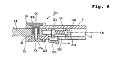
- Fig. 8 shows a holding device 201 according to a third embodiment of the present invention, which is a sectional view taken along the same plane as Fig. 4.
- the holding device 201 only the locking member and the operating member have different constructions from those of the holding device 1 of the first embodiment, but the other portions have the same constructions as those of the holding device 1. Therefore, the detailed description of the portions having the same constructions as those of the holding device 1 of the first embodiment will be omitted by designating them by the common reference numerals.
- a locking member 250 is provided in the mechanism housing space 2a of the handle 2.
- the locking member 250 has a sliding body 251 axially slidingly supported in the mechanism housing space 2a and a locking projection 253 on the front side for facing the recesses 38a, 38b, 38c, 38d and 38e and the sliding surfaces 39a, 39b, 39c and 39d provided in the rotary portion 31 of the support member 4.
- the locking member 250 also has a guide shaft 254 on the rear side, around which the compression coil spring 55 is provided, so that the locking member 250 is always biased forwardly of the handle 2 due to the spring force of the compression coil spring 55.
- the locking member 250 is provided along with a sliding button 270 as operating member.
- the sliding button 270 may be integral with or separate from the locking member 250.
- the sliding button 270 projects out of the handle 2 through the operating hole 243 so that the sliding operation of the sliding button 270 can be performed from outside the handle 2.
- the sliding button 270 is separate from the locking member 250, as the sliding button 270 is slid in the direction of the arrow, the locking member 250 is moved in the direction of the arrow with pressed by the sliding button 270. In this case, the locking member 250 and the sliding button 270 are directly or indirectly engaged together through appropriate means.
- the engagement and fixation of the locking projection to one of the recesses 38a, 38b, 38c, 38d and 38e can be released by operating the push button or the sliding button, and subsequently, the locking projection sliding on one of the sliding surfaces 39a, 39b, 39c and 39d can automatically fit in the adjacent recess.
- the position of the support member 4 can be easily changed, and the support member 4 can be always stabilized in one of the positions (i), (ii), (iii), (iv) and (v) by letting the locking projection fit in one of the recesses 38a, 38b, 38c, 38d and 38e.
- the locking mechanism since the locking mechanism is housed in the mechanism housing space of the handle so that only the push button or the sliding button projects beyond the outer periphery of the handle, the locking mechanism does not appear on the outer periphery of the handle to provide a compact appearance.
- the locking member since the locking member is provided axially movably in the handle, the locking mechanism can be housed in a thin handle. If the operating member is the push button 70 to be operated by pushing in a direction perpendicularly intersecting the shaft axis Os as shown in Figs. 3 and 7, it can be operated easily. If the operating member is the sliding button 270 to be operated by sliding in the same direction as the locking member as shown in Fig. 8, on the other hand, the locking mechanism can be made more simple to make the handle much thinner.
- the locking projection of the locking member can be made thicker within the inner diameter of the handle.
- the recesses 38a-38e of the rotary portion 31 can be of an increased width in the X-direction, the strength of engagement and fixation when the locking projection fits in one of the recesses 38a, 38b, 38c, 38d and 38e can be increased.
- the shaft axis Os of the handle and the pivot axis Or of the support member have been described as perpendicularly intersecting each other in the foregoing embodiments, the axes Os and Or need not intersect each other exactly perpendicularly, as well as a plane inclusive of the axis Os and a plane inclusive of the axis Or need not be common.
- the width of the recesses 38a, 38b, 38c, 38d and 38e formed in the rotary portion 31 may be constant in a direction normal to the pivot axis Or or may be radially increased in the normal direction.
- the locking projection of the locking member may be of any shape as long as can enter the recesses 38a, 38b, 38c, 38d and 38e to stabilize the support member 4.
- the width of the recesses 38a, 38b, 38c, 38d and 38e is radially increased as set forth above and that the locking projection is in the shape of a square rod, because the locking projection subjected to the spring force of the compression coil spring 55 can be certainly brought into contact with the slopes of the recesses 38a, 38b, 38c, 38d and 38e, so that the support member 4 can be certainly engaged and fixed through the locking projection.
- the angle between the first recess 38a and the second recess 38b, the angle between the first recess 38a and the third recess 38c, and the angle between the third recess 38c and the fourth recess 38d are all ⁇ 1 (45 degrees), but these angles between the recesses need not be equal and the angle ⁇ 1 need not be 45 degrees.
- At least a few of components constituting the handle 2, 102, the housing handle 3, the pivot connection 5 and the locking mechanism 6, 106 may be made of metal such as aluminum or alloy such as aluminum alloy, instead of synthetic resin.
- the position of the support member to which a cleaning wiper is to be attached can be changed with a simple operation.
- the support member can be stabilized in predetermined positions without causing unexpected turn.
Abstract
Description
- The present application has been filed with claiming priority based on Japanese Patent Application NO. 2002-212532, filed on July 22, 2002. Disclosure of the above-identified Japanese Patent Applications are herein incorporated by reference.
- The present invention relates to a device for holding a disposable or reusable cleaning wiper and a cleaning tool constructed of the holding device and the cleaning wiper.
- Japanese Unexamined Patent Publication Nos. 9-154791 and 9-38009 disclose cleaning tools for holding a cleaning cloth comprising nonwoven fabric and the like, in which a head for supporting the cleaning cloth is provided at a front end of a short handle or axially extendable handle that can be held with one hand.
- However, since the head disclosed in the above-mentioned Patent Publications is fixed in position so as not to move at the front end of the handle, the handle held with hand for cleaning a surface to be cleaned with the cleaning cloth attached to the head need be turned in various directions in accordance with the shape of the surface to be cleaned. Therefore, it is not suitable for cleaning a variously oriented surface to be cleaned such as furniture surface.
- On the other hand, Japanese Unexamined Patent Publication Nos. 51-85273 and 2002-17640 disclose cleaning tools in which a brush-like cleaning device is attached to a front end of a handle so as to be adjustable in position.
- More specifically, the brush-like cleaning device used for these cleaning tools is pivotally attached to the front end of the handle. In this pivot connection, a plurality of recesses are formed in an outer periphery of a rotary portion that rotates together with the cleaning device, while a locking member for fitting in the recesses are provided in the handle, so that the position of the brush-like cleaning device can be changed and fixed by fitting the locking member in the recesses.
- In the cleaning tool disclosed in Japanese Unexamined Patent Publication No. 51-85273, however, the fit of the locking member in the recess is stabilized after positioning of the cleaning device with a rotary ring, which is threadably attached to an external thread formed around the handle, tightened along the external thread. Therefore, every time the position of the cleaning device is to be changed, there will be required such an extremely laborious operation that the rotary ring is first turned in the loosening direction of the thread for changing the position of the cleaning device and then the rotary ring is turned in the tightening direction of the thread. In addition, the front end of the handle becomes not only thicker but also heavier due to the provision of the rotary ring.
- In the cleaning tool disclosed in Japanese Unexamined Patent Publication No. 2002-17640, on the other hand, after the position of the brush-like cleaning device is pivotally changed, an operating part provided in the handle should be pushed forwardly of the handle by hand so as to fit a locking part provided in the operating part into the recess. Thus, the operating part need be strongly pushed forwardly of the handle by finger for setting the cleaning device in position, so that the operation for setting the cleaning device in position becomes laborious.
- In the cleaning tools disclosed in the two Patent Publications, moreover, the locking member cannot enter the recess if the rotary ring is turned or the operating part is pushed forward by hand before the locking member is exactly confronted by the recess, so that the locking member sometimes fails in fitting into the recess. Accordingly, the operation of the rotary ring or the operating part must be done after the locking member is confronted by the recess, so that it tends to take much time to certainly fix the cleaning device in position.
- In the cleaning tools disclosed in the two Patent Publications, still moreover, although the position of the brush-like cleaning device can be changed within a predetermined angular range, the cleaning device cannot be folded back to overlie the handle. That is, the cleaning tools disclosed in the two Patent Publications are not intended to support a disposable cleaning wiper, but the brush-like cleaning device for a long time use is attached to the handle. Therefore, the holding device is intended to be left attached even when it is not used, not assuming such a usage that the cleaning tool is folded back for storage with a wiper removed therefrom, unlike a cleaning tool to which a disposable wiper is intended to be attached.
- The present invention has been worked out in view of the shortcomings in the prior art set forth above. It is therefore an object of the present invention to provide a holding device, wherein the position of a support member to which a cleaning wiper is to be attached can be changed with a simple operation and the support member can be stabilized in predetermined positions without causing unexpected turn, and a cleaning tool with the holding device.
- According to a first aspect of the present invention, there is provided a holding device for a cleaning wiper comprising:
- a handle; and
- a support member pivotally connected to a front end of the handle for supporting a cleaning wiper, the support member having a pivot axis oriented in a direction crossing a shaft axis of the handle, wherein
- the support member has sliding surfaces that are formed at a predetermined normal distance from the pivot axis and recesses that are formed toward the pivot axis from the sliding surfaces, the sliding surfaces and the recesses alternating with each other about the pivot axis, and
- the handle has a locking member capable of engaging in the recesses, the locking member being movable along the shaft axis inside the handle, the locking member being provided along with a biasing member for applying a biasing force to the locking member toward the recesses and an operating member for moving the locking member in a direction opposite to the biasing force of the biasing member.
-
- In the holding device, the locking member can be released from the recesses by moving the locking member away from the recesses against the biasing force of the biasing member, thereby permitting the support member to turn. Thereafter, when the operating force to the locking member is eliminated, the locking member moves along the axis of the handle due to the biasing force, whereby the locking member fits in one recess so that the support member goes to an engaged and fixed state (locked state).
- Here, even if the locking member is not confronted by the recess at the time when the operating force to the locking member is eliminated, the locking member subjected to the biasing force comes into contact with the sliding surface, and therefore, when the support member is turned a little in such a state, the locking member can automatically fit in the recess due to the biasing force so that the support member goes to the engaged and fixed state. That is, when the position of the support member is to be changed, the support member can automatically go to the engaged and fixed state such that the locking member is moved away from the recess by operation of the operating member, the operating member is let go of during a turn of the support member, and then the support member is turned only a little more. Thus, the operation for changing the position of the support member is quite simple.
- In the holding device, moreover, since the locking member is so provided axially movably inside the handle as to fit in the recess of the support member, the locking member can be made thick as well as the support member can be made wide at its portion having the recesses. Accordingly, the locking strength when the locking member fits in the recess can be increased. In addition, the handle can be made thin when the locking member is provided axially movably.
- Moreover, since the locking member provided in the handle along with the operating member is separate from the pivot connection, the pivot connection between the handle and the support member can be of a simple construction and the radius from the pivot axis to the sliding surfaces can be made large to increase the fixing strength when the locking member is engaged with and fixed to the recess. Accordingly, when the support member goes to the engaged and fixed state, the position of the support member can be stabilized so as not to cause unexpected change.
- The present invention may be constructed such that the sliding surfaces are formed on an imaginary cylindrical surface with center at the pivot axis.
- If the sliding surfaces are part of the cylindrical surface, when the support member is turned with the locking member in contact with the sliding surface, the locking member can smoothly slide on the sliding surface to fit into the recess. In the present invention, however, the sliding surfaces located between adjacent recesses may be flat surfaces extending in a direction tangential to an imaginary circle with center at the pivot axis.
- The present invention may be constructed such that the support member has a cleaning support surface for pressing a cleaning wiper attached thereto against a surface to be cleaned, wherein selective engagement of the locking member in the recesses permits a stepwise change of angle between the shaft axis and the cleaning support surface.
- With the stepwise change of the angle of the cleaning support surface for pressing the cleaning wiper against a surface to be cleaned, the handle can be held with hand always in suitable positions for cleaning operation, so that an object such as furniture having variously oriented surfaces to be cleaned, ceiling, and the like can be easily cleaned.
- In the present invention, it is preferred that one of the recesses is a fold locking recess and when the locking member engages in the fold locking recess, the support member is folded back to substantially overlie the handle.
- If the fold locking recess is provided, when the holding device is not used, the support member can be folded back to substantially overlie the handle with the cleaning wiper removed from the support member, for instance, so that a large storage space is not required.
- The present invention may be constructed such that the operating member is a push button that is externally exposed on an outer periphery of the handle and movable in a direction crossing the shaft axis, and at least one of the push button and the locking member has an inclined sliding surface inclined to both a direction along which the push button is to be pushed and a direction along which the locking member is movable, wherein a sliding component force acting on the inclined sliding surface as the push button is pushed permits the locking member to move against the biasing force of the biasing member.
- In the present invention, since the locking member is provided to be movable axially of the handle, the handle can be made thin, as set forth above. In this construction, if the push button is provided to be movable in a direction crossing the shaft axis of the handle, the operation for releasing the engagement and fixation (lock) between the locking member and the recess can be performed quite easily.
- Alternatively, the present invention may be constructed such that the operating member is a sliding button that is externally exposed on an outer periphery of the handle and movable along the shaft axis, wherein the sliding button permits the locking member to move against the biasing force of the biasing member.
- If the sliding button is thus provided to be movable axially of the handle, the inner structure of the handle can be made simple, and even if the handle is made thin, the locking member can be certainly operated.
- According to a second aspect of the present invention, there is provided a cleaning tool comprising: the foregoing holding device; and a cleaning wiper to be attached to the support member, wherein
the cleaning wiper is a disposable wiper comprising nonwoven fabric, paper or a combination of nonwoven fabric and a bundle of fibers, and the cleaning wiper is supported by the support member with the support member inserted into holding spaces formed in the cleaning wiper. - In this construction, since the cleaning wiper can be made soft, it can easily be attached to the support member or replaced.
- The present invention will be understood more fully from the detailed description given hereinafter and from the accompanying drawings of the preferred embodiments of the present invention, which, however, should not be taken to be limitative to the invention, but are for explanation and understanding only.
- In the drawings:
- Fig. 1A, 1B and 1C are general side views showing a holding device according to a first embodiment of the present invention, wherein a support member is in different positions;
- Fig. 2 is a perspective view showing the support member of the holding device and a cleaning wiper;
- Fig. 3 is an exploded perspective view showing a pivot connection and a locking mechanism in the holding device;
- Fig. 4 is a sectional view of the holding device taken along an XY-plane of Fig. 3;
- Figs. 5A and 5B are sectional views of the holding device taken along a YZ-plane of Fig. 3, wherein the support member is in different positions;
- Figs. 6A and 6B are sectional views of the holding device taken along the YZ-plane of Fig. 3, wherein the support member is in different positions;
- Fig. 7 is an exploded perspective view showing a locking mechanism in a holding device according to a second embodiment of the present invention; and
- Fig. 8 shows a holding device according to a third embodiment of the present invention, which is a sectional view corresponding to Fig. 4.
-
- The present invention will be discussed hereinafter in detail in terms of the preferred embodiment according to the present invention with reference to the accompanying drawings. In the following description, numerous specific details are set forth in order to provide a thorough understanding of the present invention. It will be obvious, however, to those skilled in the art that the present invention may be practiced without these specific details. In other instance, well-known structures are not shown in detail in order to avoid unnecessary obscurity of the present invention.
- Figs. 1A, 1B and 1C are general side views showing a holding device according to a first embodiment of the present invention, wherein Fig. 1A shows a state where a cleaning support surface of a support member is oriented parallel with a shaft axis of a handle, Fig. 1B shows a state where the cleaning support surface is oriented perpendicular to the shaft axis of the handle, and Fig. 1C shows a state where the support member is folded back to substantially overlie the handle.
- Fig. 2 is a perspective view showing a structure of the support member and a cleaning wiper to be attached to the support member; Fig. 3 is an exploded perspective view showing a pivot connection between the handle and the support member and a locking mechanism; Fig. 4 is a sectional view taken along an XY-plane, showing the pivot connection and the locking mechanism; and Figs 5A and 5B and Figs. 6A and 6B are sectional views taken along a YZ-plane, showing the support member in different positions.
- As shown in Figs. 1A, 1B and 1C, a holding device 1 has a
handle 2 and a housing handle 3. In Figs. 1A, 1B and 1C, thehandle 2 is illustrated as projecting forwardly from the housing handle 3, but thehandle 2 can be retracted into the housing handle 3 so as to decrease the length of the assembly of thehandle 2 and the housing handle 3. It should be noted that the housing handle 3 may be a telescopic handle so as to increase the length of the assembly of thehandle 2 and the housing handle 3. - As shown in Fig. 3 and the following Figures, the
handle 2 is a cylinder of a hollow circular cross-section. The housing handle 3 is also a cylinder of a hollow circular cross-section. Referring to Fig. 1A, the shaft axis of thehandle 2 and the housing handle 3 is indicated by Os. - A support member 4 is pivotally connected to the front end of the
handle 2 through apivot connection 5. The pivot axis of the support member 4 at thepivot connection 5 is indicated by Or. In the present embodiment, the pivot axis Or is oriented in a direction perpendicularly intersecting the shaft axis Os of thehandle 2. The support member 4 is pivotable about the pivot axis Or, and after the support member 4 is turned to respective positions, the support member 4 can be engaged and fixed (locked) by a locking mechanism 6 provided inside thehandle 2. - Referring to Fig. 1A, the lower surface of the support member 4 is a cleaning
support surface 4a for pressing acleaning wiper 8 attached to the support member 4 against a surface to be cleaned. In the present embodiment, the support member 4 can be engaged and fixed at five different positions. - Fig. 1A shows a first cleaning position (i), in which the
cleaning support surface 4a of the support member 4 is substantially parallel with the shaft axis Os of thehandle 2, a second cleaning position (ii), in which thecleaning support surface 4a is turned by 1 downwardly from the first cleaning position (i), and a third cleaning position (iii), in which thecleaning support surface 4a is turned by 1 upwardly from the first cleaning position (i). - Fig. 1B shows a fourth cleaning position (iv), in which the
cleaning support surface 4a is further turned by 1 upwardly from the third cleaning position (iii), and at this time, the cleaningsupport surface 4a becomes substantially perpendicular to the shaft axis Os. When the support member 4 is further turned clockwise by 2 from the fourth cleaning position (iv) of Fig. 1B, the support member 4 thus folded back overlies thehandle 2 to take a folded position (v), wherein the cleaningsupport surface 4a faces upward and becomes substantially parallel with the shaft axis Os. - The pivot angles 1 of the support member 4 between adjacent cleaning positions are equal, while the pivot angel 2 of the support member 4 from the fourth cleaning position (iv) to the folded position (v) is set larger than the pivot angles 1 between adjacent cleaning positions. For instance, 1 is 45 degrees, and 2 is 90 degrees.
- At the front end of the
handle 2, there is provided apush button 70 as operating member for releasing the engagement and fixation (lock) through the locking mechanism 6, wherein thepush button 70 projects outwardly beyond the outer periphery of thehandle 2. In order that thepush button 70 can be operated even when the support member 4 is folded back against thehandle 2 into the folded position (v), thepush button 70 is so positioned as not to interfere with the operation of the support member 4 in the folded position (v). - Individual components constituting the
handle 2, the housing handle 3, the support member 4, thepivot connection 5 and the locking mechanism 6 are all made of synthetic resin, such as ABS, vinyl chloride, PE (polyethylene), PP (polypropylene) and PET (polyethylene terephthalate), except for coil spring. - As shown in Fig. 2, the support body 4 has an
arm 14 extending forwardly from thepivot connection 5, and thearm 14 is bifurcated to provide support strips 11, 11 in the form of parallel flat plates. Along an outer edge of the individual support strips 11, two thindeformable projections clip 13 is integrally formed to extend forwardly between the support strips 11, 11. Here, the lower surfaces of the support strips 11, 11 are regarded as the cleaningsupport surface 4a. - The
cleaning wiper 8 of Fig. 2 is a disposable, soft wiper, of which amain body 21 comprises a nonwoven fabric, a stack of nonwoven fabrics, a stack of papers, a foamed resin material, a stack of a nonwoven fabric and a bundle of fibers that is referred to as tow, or the like. On themain body 21, laid is a holdingsheet 22 that comprises a nonwoven fabric or the like. Themain body 21 and the holdingsheet 22 are joined together at a pair of longitudinally extendingside bond lines center bond line 24 extending parallel with and between the twoside bond lines - Between the
main body 21 and the holdingsheet 22, there are formed holdingspaces side bond line 23 and thecenter bond line 24. Theindividual holding spaces 25 haveopenings main body 21. When the support strips 11, 11 of the support member 4 are inserted into the holdingspaces openings sheet 22 is pressed by theclip 13, whereby thecleaning wiper 8 attached to the support member 4 can be prevented from easily detaching therefrom. - With the
cleaning wiper 8 thus attached to the support member 4, themain body 21 of thecleaning wiper 8 beneath the cleaningsupport surface 4a (i.e., the lower surfaces of the support strips 11, 11) can be pressed against a surface to be cleaned such as floor and furniture. - It should be noted that a washable (reusable) cleaning wiper may be attached to the support member 4, in place of the disposable wiper.
- As shown in Fig. 3, the support member 4 is integrally formed, at its rear end of the
arm 14, with a generally disc-shapedrotary portion 31, and ashaft hole 32 is formed to passes through therotary portion 31 in the X-direction. Thehandle 2 is integrally formed, at its front end, with a pair of disc-shapedsupport portions support space 34 between thesupport portions support portions - The thickness of the
rotary portion 31 formed in the support member 4 is substantially equal to the width of thesupport space 34, so that therotary portion 31 can be inserted into thesupport space 34 substantially without play. As shown in Fig. 4, afirst support shaft 36a is inserted into thesupport hole 35 from outside onesupport portion 33, while asecond support shaft 36b is inserted into thesupport hole 35 from outside theother support portion 33. The first andsecond support shafts shaft hole 32 of therotary portion 31 to fit each other within theshaft hole 32, wherein the first andsecond support shafts - As a result, the
rotary portion 31, being integral with the support member 4, becomes rotatable about the first andsecond support shafts second support shafts handle 2. - As shown in Fig. 3 and Fig. 5A, the
rotary portion 31, being integral with the support member 4, has first, second third andfourth recesses individual recesses second recesses third recesses fourth recesses - Moreover, a
fold locking recess 38e is provided at a position spaced counterclockwise apart from thefourth recess 38d by 2. The 2 is 90 degrees, for instance. - Thus, a first sliding
surface 39a is provided between the first andsecond recesses surface 39b is provided between the first andthird recesses surface 39c is provided between the third andfourth recesses fourth recesses 38d and thefold locking recess 38e, furthermore, provided is afold sliding surface 39d. The individual slidingsurfaces - In the present embodiment, since the
rotary portion 31 of the support member 4 is held between thesupport portions handle 2, not only the width but also the radius R of therotary portion 31 can be made relatively large, so that the strength of engagement and fixation (locking strength) at the time when a locking projection 53 (which will be described later in detail) fits in the recess can be increased. - Next, the structure of the locking mechanism 6 will be described.
- As shown in Fig. 3, the
handle 2 is a cylinder having amechanism housing space 2a inside of it. In thehandle 2, apartition 41 is integrally formed to separate themechanism housing space 2a, at its front side adjacent thesupport portions 33, from thesupport space 34, and a rectangular window 42 is formed to pass through thepartition 41 axially of the handle 2 (i.e., along the shaft axis Os). - At a location closely spaced apart from the
support portions 33 toward the rear side (toward the housing handle 3), thehandle 2 has anoperating hole 43 passing through the cylinder wall of thehandle 2 in the X-direction. At a location spaced apart from the operatinghole 43 toward the rear side, there is also formed a small-diameterfitting hole 44 passing through the cylinder wall in the X-direction. In the inner periphery of thehandle 2, a pair of slidinggrooves handle 2 from the inward surface of thepartition 41. The slidinggrooves - Into the
mechanism housing space 2a of thehandle 2, a lockingmember 50 is inserted. The lockingmember 50 has a slidingbody 51, whose upper andlower surfaces handle 2 that defines themechanism housing space 2a, so that when the lockingmember 50 is inserted into themechanism housing space 2a, the upper andlower surfaces mechanism housing space 2a. - The sliding
body 51 also has arib 51c extending along the Y-direction on theupper surface 51a and arib 51d extending along the Y-direction on thelower surface 51b. Since theribs grooves member 50 is permitted to move axially of thehandle 2 without rotating inside themechanism housing space 2a. - In the locking
member 50, a slidingshaft 52 of a rectangular cross-section is provided axially of thehandle 2 to extend forwardly from the slidingbody 51. The slidingshaft 52 is inserted into the window 42 formed in thepartition 41. At the front end of the slidingshaft 52, the lockingprojection 53 of a rectangular cross-section is integrally formed and is permitted to project into thesupport space 34. - At its front side, the sliding
body 51 has inclined slidingsurfaces shaft 52 vertically (in the Z-direction). The inclined slidingsurfaces handle 2 extends and the X-direction along which thepush button 70 is to be pushed. - In the locking
member 50, aguide shaft 54 of a circular cross-section is integrally formed to extend rearwardly from the slidingbody 51 in the axial direction of thehandle 2. Around theguide shaft 54, acompression coil spring 55 is provided as biasing member. - In the
mechanism housing space 2a, astopper 60 is located at a position spaced apart from thepartition 41 toward the rear side. Thestopper 60, as prepared separately from thehandle 2, has a disc-shapedstopper wall 61 that is opposite thepartition 41, and acircular guide hole 62 is formed centrally of thestopper wall 61 to pass through it axially of thehandle 2. Thestopper 60 has a pair ofresilient arms stopper wall 61. As shown in Fig. 4, oneresilient arm 63 is integrally formed with afitting claw 63a for fitting in a groove formed in the inner periphery of thehandle 2, while the otherresilient arm 64 is integrally formed with afitting projection 65 for fitting in thefitting hole 44 to appear on the outer periphery of thehandle 2. - After the locking
member 50 and thecompression coil spring 55 are inserted into themechanism housing space 2a and the slidingshaft 52 is inserted into the window 42, thestopper 60 is assembled in themechanism housing space 2a such that thefitting claw 63a of theresilient arm 63 fits in the groove formed in the inner periphery of thehandle 2 while thefitting projection 65 fits in thefitting hole 44, thereby securing thestopper 60 so as not to slip off. - Then, the
guide shaft 54 of the lockingmember 50 is inserted into theguide hole 62 of thestopper wall 61, so that thecompression coil spring 55 is disposed between thepartition 41 and thestopper wall 61 in a compressed state. Due to a biasing force of thecompression coil spring 55, the lockingmember 50 is always biased toward thesupport space 34. - It should be noted that the locking
member 50 can be removed out of themechanism housing space 2a by pushing thefitting projection 65 with a finger to release thefitting projection 65 inwardly from thefitting hole 44. - In the
operating hole 43 formed in thehandle 2, thepush button 70 as operating member is disposed. Thepush button 70 is integrally formed with a pair of operatingarms arm 71 having an engagingclaw 71a that projects outwardly; theoperating arm 72 having an engaging claw (not shown) that likewise projects outwardly. Thepush button 70 is inserted into themechanism housing space 2a of thehandle 2 to project outwardly through the operatinghole 43. Thepush button 70 thus assembled is permitted to project outwardly a predetermined distance, but prevented from slipping out of theoperating hole 43 by contact of the engagingclaw 71a of theoperating arm 71 and the engaging claw (not shown) of theoperating arm 72 with a stopper (not shown) provided in themechanism housing space 2a. Thepush button 70 is provided movably in the X-direction. - The operating
arms push button 70 havecontact portions body 51 of the lockingmember 50. Thecontact portions surfaces body 51, so that thecontact portions surfaces - Next, how to operate the holding device 1 will be described.
- In the first cleaning position (i) where the cleaning
support surface 4a of the support member 4 is substantially parallel with the shaft axis Os of thehandle 2, as shown in Fig. 1A, thepivot connection 5 and the locking mechanism 6 are in the state of Fig. 5A. - In Fig. 5A, since the locking
member 50 is biased toward thesupport space 34 due to the biasing force of thecompression coil spring 55, the lockingprojection 53 integrally formed in the lockingmember 50 fits in thefirst recess 38a of therotary portion 31 provided at the rear end of the support member 4. Accordingly, the support member 4 is engaged and fixed (locked) in the first cleaning position (i) of Fig. 1A. - Here, since the
contact portions push button 70 are pressed toward thepartition 41 with the inclined slidingsurfaces member 50, thepush button 70 is projecting beyond the outer periphery of thehandle 2 due to a sliding component force of the inclined slidingsurfaces push button 70 thus projecting can be operated from outside the outer periphery by pushing. - In order to change the position of the support member 4, the
push button 70 is first pushed along the X-direction of Fig. 3. When thepush button 70 is pushed, the inclined slidingsurfaces contact portions member 50 move away from thesupport space 34 against the spring force of thecompression coil spring 55. As a result, the lockingprojection 53 of the lockingmember 50 comes out of thefirst recess 38a to release the engagement and fixation of the support member 4. - After the engagement and fixation of the support member 4 is released, the support member 4 is turned while the
push button 70 is being kept pushed, and then, the pressing force against thepush button 70 is eliminated at the time when the lockingprojection 53 is confronted by any one of therecesses member 50 moves forward due to the biasing force of thecompression coil spring 55 so that the lockingprojection 53 fits in the confronting one of the recesses for engagement and fixation of the support member 4 in a selected position. When the lockingprojection 53 fits in therecess 38b, the support member 4 is in the second cleaning position (ii); when the lockingprojection 53 fits in therecess 38c, the support member 4 is in the third cleaning position (iii); when the lockingprojection 53 fits in therecess 38d, the support member 4 is in the fourth cleaning position (iv); and when the lockingprojection 53 fits in thefold locking recess 38e, the support member 4 is in the folded position (v). - Here, it should be noted that even if the pressing force against the
push button 70 is eliminated before the lockingprojection 53 is confronted by one of the recesses during the position change of the support member 4, the lockingprojection 53 can certainly fit in one of the recesses that is the closest to the lockingprojection 53 in the turning direction of the support member 4. That is, it is not necessary to keep applying the pressing force against thepush button 70 until the lockingprojection 53 is aligned with the recess. - For instance, after the locking
projection 53 is released from thefirst recess 38a by pushing thepush button 70 to make the lockingmember 50 move rightward from the engaged and fixed position of Fig. 5A in which the lockingprojection 53 is fitting in thefirst recess 38a, the support member 4 is turned a little clockwise and the pressing force against thepush button 70 is eliminated. Then, the lockingmember 50 moves forward due to the biasing force of thecompression coil spring 55 to press the tip end of the lockingprojection 53 against the second slidingsurface 39b adjacent to thefirst recess 38a, as shown in Fig. 5B. If the support member 4 in this position is turned a little more clockwise without pushing thepush button 70, the tip end of the lockingprojection 53 subjected to the biasing force of thecompression coil spring 55 slides along the second slidingsurface 39b and then moves into thethird recess 38c automatically, thereby engaging and fixing the support member 4 in the third cleaning position (iii). - The locking
projection 53 can likewise fit in the second andfourth recesses fold locking recess 38e. Fig. 6A shows a state where the lockingprojection 53 fits in thefourth recess 38d for engaging and fixing the support member 4 in the fourth cleaning position (iv). Here, if the lockingprojection 53 is released from thefourth recess 38d by pushing thepush button 70 and then the pressing force against thepush button 70 is immediately eliminated, the tip end of the lockingprojection 53 is pressed against thefold sliding surface 39d. Accordingly, as the support member 4 is turned to the position of Fig. 6B, the tip end of the lockingprojection 53 slides along thefold sliding surface 39d and then fits in thefold locking recess 38e, thereby engaging and fixing the support member 4 in the folded position (v). - Thus, the support member 4 can be engaged and fixed in the respective positions with a simple operation that involves push and quick release of the
push button 70. Folding back the support member 4 against thehandle 2 into the folded position (v) and maintaining the support member 4 in the folded position (v) can also be performed only by pushing thepush button 70 once and subsequently turning the support member 4. - It should be noted that the operation of the
push button 70 is quite simple because thepush button 70 can be operated only by pushing in a direction perpendicularly intersecting the shaft axis Os of thehandle 2. In addition, since thepush button 70 is so positioned as not to overlap with the support member 4 in the folded position (v) of Fig. 1C, thepush button 70 can be easily pushed even in the folded position (v). - According to the present embodiment, the cleaning tool in which the
cleaning wiper 8 is attached to the support member 4 can be used for cleaning upper surfaces of furniture and the like with the cleaningsupport surface 4a of the support member 4 engaged and fixed in the first cleaning position (i) of Fig. 1A or the second cleaning position (ii) and for cleaning floor surfaces and the like with the cleaningsupport surface 4a engaged and fixed in the third cleaning position (iii) or the fourth cleaning position (iv) of Fig. 1B. Moreover, the support member 4 can be turned from the fourth cleaning position (iv) into the folded position (v) of Fig. 1C. In the folded position (v), the holding device 1 can be compactly stored with thecleaning wiper 8 removed from the support member 4. The holding device 1 in the folded position (v) can be made more compact with thehandle 2 retracted into the housing handle 3 to decrease the entire handle length for storage in a narrow space. - Fig. 7 is an exploded perspective view showing a portion of a
holding device 101 according to a second embodiment of the present invention. - The holding
device 101 has alocking mechanism 106 whose construction is different from that of the locking mechanism 6 of the first embodiment, but a lockingmember 150 provided in thelocking mechanism 106 with a different support structure operates in the same manner as the lockingmember 50 of the locking mechanism 6. Here, the support member 4 and thepivot connection 5 have the same construction as those of the holding device 1 according to the first embodiment. In addition, the pivotal operation of the support member 4 and the operation for engaging and fixing the support member 4 in the individual positions can be performed in the same manner as described with reference to Figs. 1A, 1B, 1C, 4, 5A, 5B, 6A and 6B. Hereinbelow, only the portions of the holdingdevice 101 having constructions different from those of the holding device 1 will be described. - Fig. 7 shows a
handle 102 that is of a cylindrical shape and formed, at its front end, with thesupport portions pivot connection 5 and thesupport space 34 between thesupport portions - Inside the
handle 102, a ring-shaped stopper 141 is integrally formed to project inwardly from the inner periphery, and anengaging hole 141a is formed centrally of the stopper 141 to pass through it axially of thehandle 102. Forwardly from the stopper 141, amechanism housing space 102b is provided inside thehandle 102. In themechanism housing space 102b, upper andlower wall surfaces - In the
mechanism housing space 102b, a predetermined width of engagingrib 102h is formed on theupper wall surface 102d to extend forwardly from the stopper 141, while anengaging rib 102i is also formed on thelower wall surface 102e to extend forwardly from the stopper 141. At the front end of themechanism housing space 102b, anopening 142 is formed to communicate with thesupport space 34. The opening shape of theopening 142 is such that upper andlower edges lower wall surfaces side edges - At a location between the stopper 141 and the
opening 142, thehandle 102 has anoperating hole 143 passing through the cylinder wall of thehandle 102 in the X-direction. - In the
mechanism housing space 102b of thehandle 102, aguide member 160 is housed. In theguide member 160, upper andlower surfaces lower wall surfaces mechanism housing space 102b, while side surfaces 161c and 161d are flat surfaces that match the two side wall surfaces 102f and 102g defining themechanism housing space 102b. - The
guide member 160 is integrally formed with engagingarms rear end surface 161e, and theindividual engaging arms engaging claws arms rear end surface 161e and theupper surface 161a and between therear end surface 161e and thelower surface 161b. - Here, a sliding
space 164 is formed to pass through theguide member 160 in the X-direction perpendicularly intersecting the axial direction (the Y-direction) of thehandle 102. At the front end of the slidingspace 164, awall 165 for closing theopening 142 of thehandle 102 is provided, and a rectangular slidinghole 166 is formed in thewall 165. In therear end surface 161e, on the other hand, acircular guide hole 167 is formed to communicate with the slidingspace 164. On upper and lower wall surfaces opposite one another in the Z-direction to define the slidingspace 164 therebetween, engagingprojections push button 70 from slipping out are formed to project toward the slidingspace 164. - The locking
member 150 is housed in the slidingspace 164. The lockingmember 150 functions in the same manner as the lockingmember 50 of the first embodiment, and is integrally formed, at its front end facing thesupport space 34, with a lockingprojection 151 of a rectangular cross-section.Stoppers projection 151 to project in the X-direction, wherein inclined slidingsurfaces stopper 153 in vertically opposite positions across the lockingprojection 151. The inclined slidingsurfaces surfaces member 50 of the first embodiment. - In the locking
member 150, aguide shaft 155 is integrally formed to extend rearwardly. Around theguide shaft 155, thecompression coil spring 55 is provided as biasing member. - In the
locking mechanism 106, thepush button 70 identical to that used in the first embodiment is used as operating member. - Next, the assembly of the
locking mechanism 106 will be described. - At first, the
compression coil spring 55 is disposed around theguide shaft 155 of the lockingmember 150 and then the lockingprojection 151 and theguide shaft 155 are inserted into the slidinghole 166 and theguide hole 167. This assembly is performed such that one of the lockingprojection 151 and theguide shaft 155 is inserted into thehole member 150 is assembled in theguide member 160, thecompression coil spring 55 is located between thestoppers rear end surface 161e. - Then, the
guide member 160 in which the lockingmember 150 and thecompression coil spring 55 are assembled is inserted into themechanism housing space 102b through theopening 142 of thehandle 102. When thus inserted, theshoulders guide member 160 abut against the front end surfaces of theengaging ribs arms hole 141a so that engagingclaws arms side engaging surface 141b of the stopper 141. Thus, theguide member 160 can be housed in themechanism housing space 102b while being prevented from moving axially of thehandle 102 and rotating about the shaft axis Os. It should be noted that theopening 142 of thehandle 102 is closed by thewall 165 of theguide member 160. - Thereafter, the
pivot connection 5 is assembled. At this time, the lockingprojection 151 of the lockingmember 150 fits in any one of therecesses rotary portion 31 of the support member 4 or abuts against any one of the slidingsurfaces - Finally, the
push button 70 is inserted into theoperating hole 143 from outside thehandle 102. At this time, the operatingarms push button 70 are elastically deformed to decrease the opposition interval therebetween so that the engagingclaw 71a of theoperating arm 71 and the engaging claw (not shown) of theoperating arm 72 slide along the upper and lower wall surfaces of theguide member 160 that define the slidingspace 164 therebetween. As thepush button 70 is further pushed in, the engagingclaw 71a of theoperating arm 71 and the engaging claw (not shown) of theoperating arm 72 engage the engagingprojections space 164, so that thepush button 70 is retained so as not to slip out of theguide member 160. As a result, thecontact portions arms surfaces member 150. - The
locking mechanism 106 thus assembled can operate in the same manner as the locking mechanism 6 of the first embodiment as shown in Fig. 4. That is, the lockingprojection 151 subjected to the biasing force of thecompression coil spring 55 can fit in any one of therecesses rotary portion 31. When thepush button 70 is pushed, then, the lockingmember 150 moves away from thesupport space 34 due to slide between thecontact portions surfaces projection 151 in the recess. - When the locking
member 150 and thecompression coil spring 55 are assembled in theguide member 160 and then the assembly is housed in themechanism housing space 102b of thehandle 102, as set forth above, the assembly is quite simple, so that the assembly can be performed efficiently. - Fig. 8 shows a
holding device 201 according to a third embodiment of the present invention, which is a sectional view taken along the same plane as Fig. 4. - In the
holding device 201, only the locking member and the operating member have different constructions from those of the holding device 1 of the first embodiment, but the other portions have the same constructions as those of the holding device 1. Therefore, the detailed description of the portions having the same constructions as those of the holding device 1 of the first embodiment will be omitted by designating them by the common reference numerals. - In the
holding device 201 of Fig. 8, a lockingmember 250 is provided in themechanism housing space 2a of thehandle 2. The lockingmember 250 has a slidingbody 251 axially slidingly supported in themechanism housing space 2a and a lockingprojection 253 on the front side for facing therecesses surfaces rotary portion 31 of the support member 4. The lockingmember 250 also has aguide shaft 254 on the rear side, around which thecompression coil spring 55 is provided, so that the lockingmember 250 is always biased forwardly of thehandle 2 due to the spring force of thecompression coil spring 55. - The locking
member 250 is provided along with a slidingbutton 270 as operating member. The slidingbutton 270 may be integral with or separate from the lockingmember 250. In the cylinder wall of thehandle 2, there is formed anoperating hole 243 being axially elongated slot. The slidingbutton 270 projects out of thehandle 2 through theoperating hole 243 so that the sliding operation of the slidingbutton 270 can be performed from outside thehandle 2. - In the
holding device 201, when the slidingbutton 270 is slid in the direction of the arrow of Fig. 8 from the engaged and fixed state where the lockingprojection 253 fits in thefirst recess 38a as in Fig. 5A, for instance, the lockingmember 250 moves in the direction of the arrow against the biasing force of thecompression coil spring 55, so that the lockingprojection 253 is released from thefirst recess 38a. If the support member 4 is turned a little in such a state and then the operating force to the slidingbutton 270 is eliminated, the tip end of the lockingprojection 253 abuts against the second slidingsurface 39b, as shown in Fig. 5B. By turning thesupport member 4 a little more in such a state, the lockingprojection 253 can fit in thethird recess 38c, for instance. - In the embodiment shown in Fig. 8, if the sliding
button 270 is separate from the lockingmember 250, as the slidingbutton 270 is slid in the direction of the arrow, the lockingmember 250 is moved in the direction of the arrow with pressed by the slidingbutton 270. In this case, the lockingmember 250 and the slidingbutton 270 are directly or indirectly engaged together through appropriate means. - In the foregoing embodiments, the engagement and fixation of the locking projection to one of the
recesses surfaces recesses - In the foregoing embodiments, since the locking mechanism is housed in the mechanism housing space of the handle so that only the push button or the sliding button projects beyond the outer periphery of the handle, the locking mechanism does not appear on the outer periphery of the handle to provide a compact appearance. In addition, since the locking member is provided axially movably in the handle, the locking mechanism can be housed in a thin handle. If the operating member is the
push button 70 to be operated by pushing in a direction perpendicularly intersecting the shaft axis Os as shown in Figs. 3 and 7, it can be operated easily. If the operating member is the slidingbutton 270 to be operated by sliding in the same direction as the locking member as shown in Fig. 8, on the other hand, the locking mechanism can be made more simple to make the handle much thinner. - Since the locking member is provided axially movably in the handle, moreover, the locking projection of the locking member can be made thicker within the inner diameter of the handle. In addition, since the
recesses 38a-38e of therotary portion 31 can be of an increased width in the X-direction, the strength of engagement and fixation when the locking projection fits in one of therecesses - Although the preferred embodiments of the present invention have been described in detail with reference to the accompanying drawings, the present invention should not be construed as limited to the specific embodiments, but various changes may be made without departing from the scope of the present invention.
- For instance, although the shaft axis Os of the handle and the pivot axis Or of the support member have been described as perpendicularly intersecting each other in the foregoing embodiments, the axes Os and Or need not intersect each other exactly perpendicularly, as well as a plane inclusive of the axis Os and a plane inclusive of the axis Or need not be common.
- The width of the
recesses rotary portion 31 may be constant in a direction normal to the pivot axis Or or may be radially increased in the normal direction. The locking projection of the locking member may be of any shape as long as can enter therecesses recesses compression coil spring 55 can be certainly brought into contact with the slopes of therecesses - In the foregoing embodiment, the angle between the
first recess 38a and thesecond recess 38b, the angle between thefirst recess 38a and thethird recess 38c, and the angle between thethird recess 38c and thefourth recess 38d are all 1 (45 degrees), but these angles between the recesses need not be equal and the angle 1 need not be 45 degrees. - At least a few of components constituting the
handle pivot connection 5 and thelocking mechanism 6, 106 may be made of metal such as aluminum or alloy such as aluminum alloy, instead of synthetic resin. - The present invention should not be understood as limited to the specific embodiment set out above but to include all possible embodiments which can be embodied within a scope encompassed and equivalent thereof with respect to the feature set out in the appended claims.
- According to the present invention, as has been described hereinabove, the position of the support member to which a cleaning wiper is to be attached can be changed with a simple operation. In addition, the support member can be stabilized in predetermined positions without causing unexpected turn.
Claims (7)
- A holding device for a cleaning wiper comprising:a handle (2); anda support member (4) pivotally connected to a front end of the handle (2) for supporting a cleaning wiper, the support member (4) having a pivot axis (Or) oriented in a direction crossing a shaft axis (Os) of the handle (2), whereinthe support member (4) has sliding surfaces (39a-39d) that are formed at a predetermined normal distance from the pivot axis (Or) and recesses (38a-38e) that are formed toward the pivot axis (Or) from the sliding surfaces (39a-39d), the sliding surfaces (39a-39d) and the recesses (38a-38e) alternating with each other about the pivot axis (Or), andthe handle (2) has a locking member (50) capable of engaging in the recesses (38a-38e), the locking member (50) being movable along the shaft axis (Os) inside the handle (2), the locking member (50) being provided along with a biasing member (55) for applying a biasing force to the locking member (50) toward the recesses (38a-38e) and an operating member (70, 270) for moving the locking member (50) in a direction opposite to the biasing force of the biasing member (55).
- A holding device as set forth in claim 1, wherein the sliding surfaces (39a-39d) are formed on an imaginary cylindrical surface with center at the pivot axis (Or).
- A holding device as set forth in claim 1, wherein the support member (4) has a cleaning support surface (4a) for pressing a cleaning wiper attached thereto against a surface to be cleaned, wherein selective engagement of the locking member (50) in the recesses (38a-38e) permits a stepwise change of angle between the shaft axis (Os) and the cleaning support surface (4a).
- A holding device as set forth in claim 1, wherein one of the recesses (38a-38e) is a fold locking recess (38e) and when the locking member (50) engages in the fold locking recess (38e), the support member (4) is folded back to substantially overlie the handle (2).
- A holding device as set forth in claim 1, wherein the operating member is a push button (70) that is externally exposed on an outer periphery of the handle (2) and movable in a direction crossing the shaft axis (Os), and at least one of the push button (70) and the locking member (50) has an inclined sliding surface inclined to both a direction along which the push button (70) is to be pushed and a direction along which the locking member (50) is movable, wherein a sliding component force acting on the inclined sliding surface as the push button (70) is pushed permits the locking member (50) to move against the biasing force of the biasing member (55).
- A holding device as set forth in claim 1, wherein the operating member is a sliding button (270) that is externally exposed on an outer periphery of the handle (2) and movable along the shaft axis (Os), wherein the sliding button (270) permits the locking member (50) to move against the biasing force of the biasing member (55).
- A cleaning tool comprising: the holding device of claim 1; and a cleaning wiper (8) to be attached to the support member (4), wherein
the cleaning wiper (8) is a disposable wiper comprising nonwoven fabric, paper or a combination of nonwoven fabric and a bundle of fibers, and the cleaning wiper (8) is supported by the support member (4) with the support member (4) inserted into holding spaces (25) formed in the cleaning wiper (8).
Applications Claiming Priority (3)
| Application Number | Priority Date | Filing Date | Title |
|---|---|---|---|
| JP2002212532A JP4041706B2 (en) | 2002-07-22 | 2002-07-22 | Cleaning holder and cleaning article using the cleaning holder |
| JP2002212532 | 2002-07-22 | ||
| PCT/JP2003/009156 WO2004008935A1 (en) | 2002-07-22 | 2003-07-18 | Holder and cleaning implement using the holder |
Publications (3)
| Publication Number | Publication Date |
|---|---|
| EP1523919A1 true EP1523919A1 (en) | 2005-04-20 |
| EP1523919A4 EP1523919A4 (en) | 2008-09-17 |
| EP1523919B1 EP1523919B1 (en) | 2010-11-17 |
Family
ID=30767810
Family Applications (1)
| Application Number | Title | Priority Date | Filing Date |
|---|---|---|---|
| EP03741481A Expired - Lifetime EP1523919B1 (en) | 2002-07-22 | 2003-07-18 | Holder and cleaning implement using the holder |
Country Status (16)
| Country | Link |
|---|---|
| US (1) | US7293317B2 (en) |
| EP (1) | EP1523919B1 (en) |
| JP (1) | JP4041706B2 (en) |
| KR (1) | KR101004306B1 (en) |
| CN (1) | CN1306904C (en) |
| AR (1) | AR040609A1 (en) |
| AT (1) | ATE488169T1 (en) |
| AU (1) | AU2003281463B2 (en) |
| CA (1) | CA2492582C (en) |
| DE (1) | DE60334993D1 (en) |
| EG (1) | EG24557A (en) |
| ES (1) | ES2355720T3 (en) |
| MX (1) | MXPA05000910A (en) |
| MY (1) | MY169757A (en) |
| TW (1) | TWI273901B (en) |
| WO (1) | WO2004008935A1 (en) |
Cited By (10)
| Publication number | Priority date | Publication date | Assignee | Title |
|---|---|---|---|---|
| WO2007044249A1 (en) * | 2005-09-30 | 2007-04-19 | S. C. Johnson & Son, Inc. | Extendable cleaning implement having two support heads |
| WO2008002429A1 (en) * | 2006-06-26 | 2008-01-03 | S. C. Johnson & Son, Inc. | Fringeless cleaning or dusting pad |
| WO2008048608A2 (en) * | 2006-10-18 | 2008-04-24 | S. C. Jonhson & Son, Inc. | Flexible cleaning tool with replaceable non-woven pad and cleaning fluid reservoir |
| EP2174577A1 (en) * | 2007-08-01 | 2010-04-14 | Kao Corporation | Cleaning tool, and rod-shaped tool |
| US7740412B2 (en) | 2005-01-28 | 2010-06-22 | S.C. Johnson & Son, Inc. | Method of cleaning using a device with a liquid reservoir and replaceable non-woven pad |
| US7886396B2 (en) | 2004-12-14 | 2011-02-15 | S.C. Johnson & Son, Inc. | Adjustable holder for cleaning implement having two support heads |
| US7976235B2 (en) | 2005-01-28 | 2011-07-12 | S.C. Johnson & Son, Inc. | Cleaning kit including duster and spray |
| ITPD20120137A1 (en) * | 2012-05-04 | 2013-11-05 | T T S S R L Tecno Trolley System | BASE FOR MOP EQUIPPED WITH ROTATION LIMITER |
| US8893347B2 (en) | 2007-02-06 | 2014-11-25 | S.C. Johnson & Son, Inc. | Cleaning or dusting pad with attachment member holder |
| ITMI20131818A1 (en) * | 2013-11-04 | 2015-05-05 | Nespoli Group S P A | DEVICE FOR REMOVAL OF HAIRS, PELUCCHI AND OTHER FROM FABRICS AND / OR CLOTHES |
Families Citing this family (71)
| Publication number | Priority date | Publication date | Assignee | Title |
|---|---|---|---|---|
| JP4463062B2 (en) * | 2004-09-30 | 2010-05-12 | リョービ株式会社 | Working machine |
| JP4785369B2 (en) | 2004-11-16 | 2011-10-05 | ユニ・チャーム株式会社 | Cleaning goods |
| TWM272500U (en) * | 2004-12-22 | 2005-08-11 | Rock Tone Entpr Co Ltd | Dust removal whisk structure |
| US8931971B2 (en) * | 2005-01-28 | 2015-01-13 | S.C. Johnson & Son, Inc. | Cleaning pad impregnated with a volatile liquid for improved dust adhesion |
| US20060171767A1 (en) * | 2005-01-28 | 2006-08-03 | Hoadley David A | Cleaning device with liquid reservoir and replaceable non-woven pad |
| US7566671B2 (en) * | 2005-01-28 | 2009-07-28 | S.C. Johnson & Son, Inc. | Cleaning or dusting pad |
| SE530086C2 (en) * | 2005-06-30 | 2008-02-26 | Haakan Kronogaard | Implements and procedure for its use |
| ES2388746T3 (en) * | 2005-10-19 | 2012-10-18 | Kao Corporation | Cleaning tool |
| JP4657075B2 (en) * | 2005-10-21 | 2011-03-23 | 花王株式会社 | Cleaning goods |
| WO2007102254A1 (en) * | 2006-03-09 | 2007-09-13 | Kao Corporation | Cleaning article, fiber raising method for the article, and production method for the article |
| US7650665B2 (en) | 2006-07-18 | 2010-01-26 | Kimberly-Clark Worlwide, Inc. | Mop assembly with fastener channels |
| US7574768B2 (en) * | 2006-07-18 | 2009-08-18 | Kimberly-Clark Worldwide, Inc. | Quick-release handle and interchangeable cleaning system |
| US7735182B2 (en) * | 2006-07-18 | 2010-06-15 | Kimberly-Clark Worldwide, Inc. | Mop assembly with reversible head |
| US7624468B2 (en) * | 2006-07-18 | 2009-12-01 | Kimberly-Clark Worldwide, Inc. | Wet mop with multi-layer substrate |
| US20080052856A1 (en) * | 2006-08-31 | 2008-03-06 | George Lin | Angle-adjustable bath brush |
| JP4976211B2 (en) * | 2007-06-20 | 2012-07-18 | ユニ・チャーム株式会社 | Cleaning tool |
| ITMO20070215A1 (en) * | 2007-06-22 | 2008-12-23 | Nuova F Lli Dondi S R L | TOOL TO CLEAN SURFACES |
| JP5001079B2 (en) * | 2007-07-10 | 2012-08-15 | 花王株式会社 | Cleaning tool |
| JP5119069B2 (en) * | 2008-07-11 | 2013-01-16 | キクロン株式会社 | Cleaning tool mounting structure |
| US8578564B2 (en) | 2009-11-05 | 2013-11-12 | The Procter & Gamble Company | Handle for removable cleaning implement |
| EP4085813A1 (en) | 2010-04-29 | 2022-11-09 | Diversey, Inc. | Floor cleaning tool |
| JP5606397B2 (en) * | 2011-05-31 | 2014-10-15 | 株式会社オーエ | Cleaning tool |
| CN103040420B (en) * | 2011-10-17 | 2015-11-25 | 杨雅菁 | Collapsible dedusting duster |
| US9408522B2 (en) | 2012-03-09 | 2016-08-09 | 3M Innovative Properties Company | Fryer cleaning tool with cleaning head with cleaning pad slidably mountable thereon |
| TW201340926A (en) * | 2012-04-13 | 2013-10-16 | Ya-Jing Yang | Automatically foldable length-variable duster handle |
| US9351624B2 (en) | 2012-06-18 | 2016-05-31 | S. C. Johnson & Son, Inc. | Cleaning implement |
| US9775486B2 (en) | 2012-11-09 | 2017-10-03 | 3M Innovative Properties Company | Cleaning pad with support body |
| CN103022079B (en) | 2012-12-12 | 2015-05-20 | 京东方科技集团股份有限公司 | Array substrate, preparation method of array substrate and organic light emitting diode display device |
| TWI576079B (en) * | 2013-03-28 | 2017-04-01 | Oimo Ind Co Ltd | Three-dimensional cyclone dust |
| US20150121728A1 (en) * | 2013-11-01 | 2015-05-07 | Black Diamond Equipment, Ltd. | Dual mode collaapsable shovel |
| USD779143S1 (en) | 2014-04-25 | 2017-02-14 | Unger Marketing International, Llc | Window scraper |
| EP2995321B1 (en) | 2014-09-15 | 2017-07-26 | Procter & Gamble International Operations SA | A consumer goods product comprising chitin nanofibrils, lignin and a polymer or co-polymer |
| US20160106294A1 (en) | 2014-10-16 | 2016-04-21 | The Procter & Gamble Company | Kit having a package containing cleaning implements, package therefor and blank therefor |
| USD782271S1 (en) | 2015-04-29 | 2017-03-28 | Unger Marketing International, Llc | Tool handle |
| WO2016175903A1 (en) * | 2015-04-29 | 2016-11-03 | Unger Marketing International, Llc | Versatile cleaning devices |
| KR101686044B1 (en) | 2015-07-14 | 2016-12-13 | 신만철 | Mop stick for multiple using |
| CN204889883U (en) * | 2015-07-27 | 2015-12-23 | 嘉兴捷顺旅游制品有限公司 | Flat mops |
| JP6490537B2 (en) * | 2015-08-21 | 2019-03-27 | 株式会社ダスキン | One side push button type wiping body holder and cleaning tool |
| JP6588805B2 (en) * | 2015-11-10 | 2019-10-09 | 株式会社アイセン | Foldable cleaning tool |
| JP6588811B2 (en) * | 2015-12-07 | 2019-10-09 | 株式会社アイセン | Two-member connecting structure and cleaning tool using the same |
| EP3390719B1 (en) | 2015-12-15 | 2021-03-03 | The Procter and Gamble Company | Fibrous structures comprising regions having different micro-ct intensive property values and associated transition slopes |
| US10428464B2 (en) | 2015-12-15 | 2019-10-01 | The Procter & Gamble Company | Fibrous structures comprising three or more regions |
| WO2017106416A1 (en) | 2015-12-15 | 2017-06-22 | The Procter & Gamble Company | Pre-moistened fibrous structures exhibiting increased mileage |
| WO2017106422A1 (en) | 2015-12-15 | 2017-06-22 | The Procter & Gamble Company | Compressible pre-moistened fibrous structures |
| PL3390721T3 (en) | 2015-12-15 | 2021-08-09 | The Procter & Gamble Company | Pre-moistened fibrous structures exhibiting increased capacity |
| EP3390718B1 (en) | 2015-12-15 | 2021-03-03 | The Procter and Gamble Company | Fibrous structures comprising regions having different solid additive levels |
| WO2017106421A2 (en) | 2015-12-15 | 2017-06-22 | The Procter & Gamble Company | Pre-moistened fibrous structures |
| US9963230B2 (en) | 2016-01-11 | 2018-05-08 | The Procter & Gamble Company | Aerial drone cleaning device and method of cleaning a target surface therewith |
| US10702121B2 (en) * | 2016-02-17 | 2020-07-07 | Ecolab Usa Inc. | Cleaning tool with removable sock |
| KR101769706B1 (en) | 2016-03-14 | 2017-08-21 | 신만철 | Mop holder for cleaning |
| WO2017160899A1 (en) | 2016-03-15 | 2017-09-21 | The Procter & Gamble Company | Method and apparatus for manufacturing an absorbent article including an ultra short pulse laser source |
| WO2017160901A1 (en) | 2016-03-15 | 2017-09-21 | The Procter & Gamble Company | Method and apparatus for manufacturing an absorbent article including an ultra short pulse laser source |
| EP3429526B1 (en) | 2016-03-15 | 2019-12-18 | The Procter and Gamble Company | Method and apparatus for manufacturing an absorbent article including an ultra short pulse laser source |
| US11172803B2 (en) | 2016-08-12 | 2021-11-16 | The Procter & Gamble Company | Cleaning sheets having coating thereon |
| WO2018106853A1 (en) | 2016-12-08 | 2018-06-14 | The Procter & Gamble Company | Pre-moistened cleaning pads |
| CA3043530C (en) | 2016-12-08 | 2021-06-01 | The Procter & Gamble Company | Cleaning pad with split core fibrous structures |
| US11622664B2 (en) | 2016-12-08 | 2023-04-11 | The Procter & Gamble Company | Fibrous structures having a contact surface |
| EP3720689B1 (en) | 2017-12-07 | 2023-07-19 | The Procter & Gamble Company | Flexible bonding |
| EP3731714A4 (en) * | 2017-12-27 | 2020-12-23 | SharkNinja Operating LLC | Cleaning apparatus with selectable combing unit for removing debris from cleaning roller |
| JP6567116B1 (en) | 2018-03-20 | 2019-08-28 | ユニ・チャーム株式会社 | Arm for cleaning tool |
| JP7008553B2 (en) | 2018-03-20 | 2022-01-25 | ユニ・チャーム株式会社 | Cleaning tool |
| CN108406676B (en) * | 2018-03-30 | 2023-09-08 | 钦州学院 | Ship base cushion block-based grinding and matching method |
| US11135707B2 (en) * | 2018-04-26 | 2021-10-05 | Hersh Designs LLC | Wrench assembly |
| US11759085B2 (en) | 2018-05-29 | 2023-09-19 | Unger Marketing International, Llc | Floor cleaning system |
| US11389986B2 (en) | 2018-12-06 | 2022-07-19 | The Procter & Gamble Company | Compliant anvil |
| USD922712S1 (en) | 2019-01-28 | 2021-06-15 | Unger Marketing International, Llc | Flat headed mop |
| USD923896S1 (en) | 2019-05-28 | 2021-06-29 | Unger Marketing International, Llc | Floor cleaning system |
| USD915703S1 (en) | 2019-05-28 | 2021-04-06 | Unger Marketng International, Llc | Flat headed mop |
| DE102020108193A1 (en) * | 2020-03-25 | 2021-09-30 | Airbus Operations Gmbh | Multipurpose tool for flight attendants |
| US11219995B1 (en) * | 2020-10-29 | 2022-01-11 | Lone Star College System District | Pivoting assembly, tool, and method of use |
| KR102349700B1 (en) * | 2020-12-14 | 2022-01-12 | 정연우 | Multipurpose cleaning device |
Citations (7)
| Publication number | Priority date | Publication date | Assignee | Title |
|---|---|---|---|---|
| US612491A (en) * | 1898-10-18 | John j | ||
| US881782A (en) * | 1907-04-24 | 1908-03-10 | George F Elliott | Intrenching-tool. |
| US5414889A (en) * | 1994-01-14 | 1995-05-16 | M. B. Walton, Inc. | Broom with position-maintaining multi-angle handle interconnector |
| JPH09154791A (en) * | 1995-12-08 | 1997-06-17 | Kao Corp | Cleaning cloth and cleaning tool |
| US5862723A (en) * | 1997-06-20 | 1999-01-26 | Rowlands; Albert J. | Pivot head wrench |
| US6315341B1 (en) * | 2000-08-11 | 2001-11-13 | Sandra Leon | Shovel having an adjustable blade angle |
| JP2002017640A (en) * | 2000-07-04 | 2002-01-22 | Teramoto Corp | Head holder for cleaning utensil |
Family Cites Families (19)
| Publication number | Priority date | Publication date | Assignee | Title |
|---|---|---|---|---|
| US261894A (en) * | 1882-08-01 | Manure-fork | ||
| US357408A (en) * | 1887-02-08 | Spade | ||
| US1427865A (en) * | 1921-11-22 | 1922-09-05 | Szabo Joseph | Digging implement |
| US1570189A (en) * | 1924-12-17 | 1926-01-19 | Sturm John Simon | Adjustable shovel |
| US2740146A (en) * | 1953-06-09 | 1956-04-03 | Sidney P Vaughn | Sponge mop with adjustable handle and squeezer means |
| JPS5185273A (en) * | 1975-01-22 | 1976-07-26 | Takeshi Abiru | BURASHIHORUDAA |
| JPS5340271A (en) | 1976-09-27 | 1978-04-12 | Hitachi Ltd | Semiconductor diffusing method |
| CN85202172U (en) * | 1985-06-11 | 1986-03-26 | 郭家明 | Multifunction room cleanser |
| US4658461A (en) * | 1985-10-02 | 1987-04-21 | The Wooster Brush Company | Flat pad applicator |
| JPH0361057U (en) * | 1989-10-17 | 1991-06-14 | ||
| US5110230A (en) * | 1991-02-22 | 1992-05-05 | Cole Jr Mark F | Adjustable swimming-pool cleaning tool |
| CN2164785Y (en) * | 1993-04-13 | 1994-05-18 | 李志明 | Multifunctional cleaning wiper |
| JPH0938009A (en) | 1995-08-01 | 1997-02-10 | Kao Corp | Cloth, handle and tool for cleaning |
| JPH1043116A (en) | 1996-08-05 | 1998-02-17 | Kao Corp | Handle for cleaning tool |
| JPH10309251A (en) * | 1997-05-13 | 1998-11-24 | Lion Corp | Cleaner |
| US5926896A (en) * | 1997-11-25 | 1999-07-27 | Rubbermaid Commercial Products Llc | Collapsible cleaning implement |
| US5960509A (en) * | 1998-02-18 | 1999-10-05 | Wu; Chia-Hao | Multi-functional back brush |
| JP3061057U (en) * | 1999-01-27 | 1999-09-14 | 株式会社東北石橋 | Swivel head type brush with handle |
| JP4643819B2 (en) * | 2000-12-11 | 2011-03-02 | 株式会社ダスキン | Mop gripper with handle |
-
2002
- 2002-07-22 JP JP2002212532A patent/JP4041706B2/en not_active Expired - Lifetime
-
2003
- 2003-07-14 TW TW092119159A patent/TWI273901B/en not_active IP Right Cessation
- 2003-07-17 MY MYPI20032694A patent/MY169757A/en unknown
- 2003-07-18 EP EP03741481A patent/EP1523919B1/en not_active Expired - Lifetime
- 2003-07-18 DE DE60334993T patent/DE60334993D1/en not_active Expired - Lifetime
- 2003-07-18 CN CNB038164426A patent/CN1306904C/en not_active Expired - Fee Related
- 2003-07-18 ES ES03741481T patent/ES2355720T3/en not_active Expired - Lifetime
- 2003-07-18 AT AT03741481T patent/ATE488169T1/en not_active IP Right Cessation
- 2003-07-18 AU AU2003281463A patent/AU2003281463B2/en not_active Ceased
- 2003-07-18 WO PCT/JP2003/009156 patent/WO2004008935A1/en active Application Filing
- 2003-07-18 CA CA002492582A patent/CA2492582C/en not_active Expired - Lifetime
- 2003-07-18 MX MXPA05000910A patent/MXPA05000910A/en active IP Right Grant
- 2003-07-18 KR KR1020057001090A patent/KR101004306B1/en active IP Right Grant
- 2003-07-21 AR AR20030102611A patent/AR040609A1/en active IP Right Grant
- 2003-07-22 EG EG2003070713A patent/EG24557A/en active
-
2004
- 2004-12-14 US US11/012,949 patent/US7293317B2/en not_active Expired - Fee Related
Patent Citations (7)
| Publication number | Priority date | Publication date | Assignee | Title |
|---|---|---|---|---|
| US612491A (en) * | 1898-10-18 | John j | ||
| US881782A (en) * | 1907-04-24 | 1908-03-10 | George F Elliott | Intrenching-tool. |
| US5414889A (en) * | 1994-01-14 | 1995-05-16 | M. B. Walton, Inc. | Broom with position-maintaining multi-angle handle interconnector |
| JPH09154791A (en) * | 1995-12-08 | 1997-06-17 | Kao Corp | Cleaning cloth and cleaning tool |
| US5862723A (en) * | 1997-06-20 | 1999-01-26 | Rowlands; Albert J. | Pivot head wrench |
| JP2002017640A (en) * | 2000-07-04 | 2002-01-22 | Teramoto Corp | Head holder for cleaning utensil |
| US6315341B1 (en) * | 2000-08-11 | 2001-11-13 | Sandra Leon | Shovel having an adjustable blade angle |
Non-Patent Citations (1)
| Title |
|---|
| See also references of WO2004008935A1 * |
Cited By (19)
| Publication number | Priority date | Publication date | Assignee | Title |
|---|---|---|---|---|
| US7802340B2 (en) | 2004-12-14 | 2010-09-28 | S.C. Johnson & Son, Inc. | Extendable cleaning implement having two support heads |
| US7886396B2 (en) | 2004-12-14 | 2011-02-15 | S.C. Johnson & Son, Inc. | Adjustable holder for cleaning implement having two support heads |
| US8657515B2 (en) | 2005-01-28 | 2014-02-25 | S.C. Johnson & Son, Inc. | Cleaning kit including duster and spray |
| US7740412B2 (en) | 2005-01-28 | 2010-06-22 | S.C. Johnson & Son, Inc. | Method of cleaning using a device with a liquid reservoir and replaceable non-woven pad |
| US7891898B2 (en) | 2005-01-28 | 2011-02-22 | S.C. Johnson & Son, Inc. | Cleaning pad for wet, damp or dry cleaning |
| US7976235B2 (en) | 2005-01-28 | 2011-07-12 | S.C. Johnson & Son, Inc. | Cleaning kit including duster and spray |
| WO2007044249A1 (en) * | 2005-09-30 | 2007-04-19 | S. C. Johnson & Son, Inc. | Extendable cleaning implement having two support heads |
| WO2008002429A1 (en) * | 2006-06-26 | 2008-01-03 | S. C. Johnson & Son, Inc. | Fringeless cleaning or dusting pad |
| WO2008048608A2 (en) * | 2006-10-18 | 2008-04-24 | S. C. Jonhson & Son, Inc. | Flexible cleaning tool with replaceable non-woven pad and cleaning fluid reservoir |
| WO2008048608A3 (en) * | 2006-10-18 | 2008-06-12 | S C Jonhson & Son Inc | Flexible cleaning tool with replaceable non-woven pad and cleaning fluid reservoir |
| US8893347B2 (en) | 2007-02-06 | 2014-11-25 | S.C. Johnson & Son, Inc. | Cleaning or dusting pad with attachment member holder |
| EP2174577A1 (en) * | 2007-08-01 | 2010-04-14 | Kao Corporation | Cleaning tool, and rod-shaped tool |
| US8595884B2 (en) | 2007-08-01 | 2013-12-03 | Kao Corporation | Cleaning tool and stick-like tool |
| US8813298B2 (en) | 2007-08-01 | 2014-08-26 | Kao Corporation | Cleaning tool and stick-like tool |
| EP2174577A4 (en) * | 2007-08-01 | 2010-12-15 | Kao Corp | Cleaning tool, and rod-shaped tool |
| WO2013164800A1 (en) * | 2012-05-04 | 2013-11-07 | T.T.S. S.R.L. | Mop base fitted with a hinged rotation limiter |
| ITPD20120137A1 (en) * | 2012-05-04 | 2013-11-05 | T T S S R L Tecno Trolley System | BASE FOR MOP EQUIPPED WITH ROTATION LIMITER |
| RU2598144C2 (en) * | 2012-05-04 | 2016-09-20 | Т.Т.С. С.Р.Л. | Mop base fitted with a hinged rotation limiter |
| ITMI20131818A1 (en) * | 2013-11-04 | 2015-05-05 | Nespoli Group S P A | DEVICE FOR REMOVAL OF HAIRS, PELUCCHI AND OTHER FROM FABRICS AND / OR CLOTHES |
Also Published As
| Publication number | Publication date |
|---|---|
| AU2003281463A1 (en) | 2004-02-09 |
| WO2004008935A1 (en) | 2004-01-29 |
| EG24557A (en) | 2009-10-12 |
| CA2492582C (en) | 2008-07-29 |
| CN1306904C (en) | 2007-03-28 |
| EP1523919A4 (en) | 2008-09-17 |
| US20050102781A1 (en) | 2005-05-19 |
| MY169757A (en) | 2019-05-15 |
| ES2355720T3 (en) | 2011-03-30 |
| CA2492582A1 (en) | 2004-01-29 |
| TW200401623A (en) | 2004-02-01 |
| TWI273901B (en) | 2007-02-21 |
| JP4041706B2 (en) | 2008-01-30 |
| AR040609A1 (en) | 2005-04-13 |
| CN1668240A (en) | 2005-09-14 |
| JP2004049619A (en) | 2004-02-19 |
| EP1523919B1 (en) | 2010-11-17 |
| AU2003281463B2 (en) | 2009-01-08 |
| US7293317B2 (en) | 2007-11-13 |
| DE60334993D1 (en) | 2010-12-30 |
| MXPA05000910A (en) | 2005-03-23 |
| KR101004306B1 (en) | 2010-12-28 |
| ATE488169T1 (en) | 2010-12-15 |
| KR20050026502A (en) | 2005-03-15 |
Similar Documents
| Publication | Publication Date | Title |
|---|---|---|
| AU2003281463B2 (en) | Holder and cleaning implement using the holder | |
| US8156603B2 (en) | Cleaning tool | |
| US5937471A (en) | Multipurpose floor cleaning device | |
| US7055204B2 (en) | Cleaning device | |
| EP1974648B1 (en) | Cleaning element and cleaning tool | |
| CA2627876C (en) | Cleaning element and cleaning tool | |
| JP4404752B2 (en) | clip | |
| JP4113740B2 (en) | Cleaning holder and cleaning article using the cleaning holder | |
| JP6656880B2 (en) | Opening / closing method of cover with cleaning tool and cleaning tool with cover | |
| JP6490537B2 (en) | One side push button type wiping body holder and cleaning tool | |
| JP3182554B2 (en) | Replacement blade for hair comb razor and razor for hair comb | |
| JP2002017640A (en) | Head holder for cleaning utensil | |
| JP4508989B2 (en) | Cleaning tool | |
| JP2010274026A (en) | Mop and set of mop and storage case | |
| JP5961425B2 (en) | Cleaning body holder, cleaning tool | |
| JP5114231B2 (en) | Cleaning member and cleaning tool provided with the cleaning member | |
| JP2001218719A (en) | Mop holder with handle | |
| CN113825437A (en) | Cleaning tool | |
| JP3208914U (en) | Binding tool and file with the same | |
| JPH081906Y2 (en) | File binding tool | |
| JP2023037164A (en) | dustpan | |
| CN113840563A (en) | Cleaning tool |
Legal Events
| Date | Code | Title | Description |
|---|---|---|---|
| PUAI | Public reference made under article 153(3) epc to a published international application that has entered the european phase |
Free format text: ORIGINAL CODE: 0009012 |
|
| 17P | Request for examination filed |
Effective date: 20041209 |
|
| AK | Designated contracting states |
Kind code of ref document: A1 Designated state(s): AT BE BG CH CY CZ DE DK EE ES FI FR GB GR HU IE IT LI LU MC NL PT RO SE SI SK TR |
|
| AX | Request for extension of the european patent |
Extension state: AL LT LV MK |
|
| DAX | Request for extension of the european patent (deleted) | ||
| A4 | Supplementary search report drawn up and despatched |
Effective date: 20080819 |
|
| 17Q | First examination report despatched |
Effective date: 20081111 |
|
| GRAP | Despatch of communication of intention to grant a patent |
Free format text: ORIGINAL CODE: EPIDOSNIGR1 |
|
| GRAS | Grant fee paid |
Free format text: ORIGINAL CODE: EPIDOSNIGR3 |
|
| GRAA | (expected) grant |
Free format text: ORIGINAL CODE: 0009210 |
|
| AK | Designated contracting states |
Kind code of ref document: B1 Designated state(s): AT BE BG CH CY CZ DE DK EE ES FI FR GB GR HU IE IT LI LU MC NL PT RO SE SI SK TR |
|
| REG | Reference to a national code |
Ref country code: GB Ref legal event code: FG4D |
|
| REG | Reference to a national code |
Ref country code: CH Ref legal event code: EP |
|
| REG | Reference to a national code |
Ref country code: IE Ref legal event code: FG4D |
|
| REF | Corresponds to: |
Ref document number: 60334993 Country of ref document: DE Date of ref document: 20101230 Kind code of ref document: P |
|
| REG | Reference to a national code |
Ref country code: NL Ref legal event code: T3 |
|
| REG | Reference to a national code |
Ref country code: ES Ref legal event code: FG2A Ref document number: 2355720 Country of ref document: ES Kind code of ref document: T3 Effective date: 20110330 |
|
| REG | Reference to a national code |
Ref country code: SK Ref legal event code: T3 Ref document number: E 8580 Country of ref document: SK |
|
| PG25 | Lapsed in a contracting state [announced via postgrant information from national office to epo] |
Ref country code: BG Free format text: LAPSE BECAUSE OF FAILURE TO SUBMIT A TRANSLATION OF THE DESCRIPTION OR TO PAY THE FEE WITHIN THE PRESCRIBED TIME-LIMIT Effective date: 20110217 Ref country code: PT Free format text: LAPSE BECAUSE OF FAILURE TO SUBMIT A TRANSLATION OF THE DESCRIPTION OR TO PAY THE FEE WITHIN THE PRESCRIBED TIME-LIMIT Effective date: 20110317 Ref country code: SI Free format text: LAPSE BECAUSE OF FAILURE TO SUBMIT A TRANSLATION OF THE DESCRIPTION OR TO PAY THE FEE WITHIN THE PRESCRIBED TIME-LIMIT Effective date: 20101117 Ref country code: AT Free format text: LAPSE BECAUSE OF FAILURE TO SUBMIT A TRANSLATION OF THE DESCRIPTION OR TO PAY THE FEE WITHIN THE PRESCRIBED TIME-LIMIT Effective date: 20101117 Ref country code: FI Free format text: LAPSE BECAUSE OF FAILURE TO SUBMIT A TRANSLATION OF THE DESCRIPTION OR TO PAY THE FEE WITHIN THE PRESCRIBED TIME-LIMIT Effective date: 20101117 Ref country code: CY Free format text: LAPSE BECAUSE OF FAILURE TO SUBMIT A TRANSLATION OF THE DESCRIPTION OR TO PAY THE FEE WITHIN THE PRESCRIBED TIME-LIMIT Effective date: 20101117 Ref country code: SE Free format text: LAPSE BECAUSE OF FAILURE TO SUBMIT A TRANSLATION OF THE DESCRIPTION OR TO PAY THE FEE WITHIN THE PRESCRIBED TIME-LIMIT Effective date: 20101117 |
|
| REG | Reference to a national code |
Ref country code: HU Ref legal event code: AG4A Ref document number: E010189 Country of ref document: HU |
|
| PG25 | Lapsed in a contracting state [announced via postgrant information from national office to epo] |
Ref country code: EE Free format text: LAPSE BECAUSE OF FAILURE TO SUBMIT A TRANSLATION OF THE DESCRIPTION OR TO PAY THE FEE WITHIN THE PRESCRIBED TIME-LIMIT Effective date: 20101117 |
|
| PG25 | Lapsed in a contracting state [announced via postgrant information from national office to epo] |
Ref country code: RO Free format text: LAPSE BECAUSE OF FAILURE TO SUBMIT A TRANSLATION OF THE DESCRIPTION OR TO PAY THE FEE WITHIN THE PRESCRIBED TIME-LIMIT Effective date: 20101117 Ref country code: DK Free format text: LAPSE BECAUSE OF FAILURE TO SUBMIT A TRANSLATION OF THE DESCRIPTION OR TO PAY THE FEE WITHIN THE PRESCRIBED TIME-LIMIT Effective date: 20101117 |
|
| PLBE | No opposition filed within time limit |
Free format text: ORIGINAL CODE: 0009261 |
|
| STAA | Information on the status of an ep patent application or granted ep patent |
Free format text: STATUS: NO OPPOSITION FILED WITHIN TIME LIMIT |
|
| 26N | No opposition filed |
Effective date: 20110818 |
|
| REG | Reference to a national code |
Ref country code: DE Ref legal event code: R097 Ref document number: 60334993 Country of ref document: DE Effective date: 20110818 |
|
| PG25 | Lapsed in a contracting state [announced via postgrant information from national office to epo] |
Ref country code: MC Free format text: LAPSE BECAUSE OF NON-PAYMENT OF DUE FEES Effective date: 20110731 |
|
| REG | Reference to a national code |
Ref country code: CH Ref legal event code: PL |
|
| PG25 | Lapsed in a contracting state [announced via postgrant information from national office to epo] |
Ref country code: CH Free format text: LAPSE BECAUSE OF NON-PAYMENT OF DUE FEES Effective date: 20110731 Ref country code: LI Free format text: LAPSE BECAUSE OF NON-PAYMENT OF DUE FEES Effective date: 20110731 |
|
| PG25 | Lapsed in a contracting state [announced via postgrant information from national office to epo] |
Ref country code: TR Free format text: LAPSE BECAUSE OF FAILURE TO SUBMIT A TRANSLATION OF THE DESCRIPTION OR TO PAY THE FEE WITHIN THE PRESCRIBED TIME-LIMIT Effective date: 20101117 |
|
| REG | Reference to a national code |
Ref country code: GR Ref legal event code: EP Ref document number: 20100402950 Country of ref document: GR Effective date: 20110119 |
|
| REG | Reference to a national code |
Ref country code: FR Ref legal event code: PLFP Year of fee payment: 14 |
|
| REG | Reference to a national code |
Ref country code: FR Ref legal event code: PLFP Year of fee payment: 15 |
|
| REG | Reference to a national code |
Ref country code: FR Ref legal event code: PLFP Year of fee payment: 16 |
|
| PGFP | Annual fee paid to national office [announced via postgrant information from national office to epo] |
Ref country code: GR Payment date: 20210611 Year of fee payment: 19 Ref country code: IT Payment date: 20210610 Year of fee payment: 19 Ref country code: NL Payment date: 20210615 Year of fee payment: 19 Ref country code: SK Payment date: 20210615 Year of fee payment: 19 Ref country code: FR Payment date: 20210611 Year of fee payment: 19 Ref country code: CZ Payment date: 20210629 Year of fee payment: 19 |
|
| PGFP | Annual fee paid to national office [announced via postgrant information from national office to epo] |
Ref country code: BE Payment date: 20210617 Year of fee payment: 19 Ref country code: GB Payment date: 20210623 Year of fee payment: 19 |
|
| PGFP | Annual fee paid to national office [announced via postgrant information from national office to epo] |
Ref country code: LU Payment date: 20210712 Year of fee payment: 19 Ref country code: IE Payment date: 20210712 Year of fee payment: 19 |
|
| PGFP | Annual fee paid to national office [announced via postgrant information from national office to epo] |
Ref country code: ES Payment date: 20210804 Year of fee payment: 19 Ref country code: HU Payment date: 20210616 Year of fee payment: 19 Ref country code: DE Payment date: 20210622 Year of fee payment: 19 |
|
| REG | Reference to a national code |
Ref country code: DE Ref legal event code: R119 Ref document number: 60334993 Country of ref document: DE |
|
| REG | Reference to a national code |
Ref country code: NL Ref legal event code: MM Effective date: 20220801 |
|
| REG | Reference to a national code |
Ref country code: SK Ref legal event code: MM4A Ref document number: E 8580 Country of ref document: SK Effective date: 20220718 |
|
| GBPC | Gb: european patent ceased through non-payment of renewal fee |
Effective date: 20220718 |
|
| REG | Reference to a national code |
Ref country code: BE Ref legal event code: MM Effective date: 20220731 |
|
| PG25 | Lapsed in a contracting state [announced via postgrant information from national office to epo] |
Ref country code: LU Free format text: LAPSE BECAUSE OF NON-PAYMENT OF DUE FEES Effective date: 20220718 Ref country code: FR Free format text: LAPSE BECAUSE OF NON-PAYMENT OF DUE FEES Effective date: 20220731 Ref country code: CZ Free format text: LAPSE BECAUSE OF NON-PAYMENT OF DUE FEES Effective date: 20220718 |
|
| PG25 | Lapsed in a contracting state [announced via postgrant information from national office to epo] |
Ref country code: SK Free format text: LAPSE BECAUSE OF NON-PAYMENT OF DUE FEES Effective date: 20220718 Ref country code: HU Free format text: LAPSE BECAUSE OF NON-PAYMENT OF DUE FEES Effective date: 20220719 Ref country code: GR Free format text: LAPSE BECAUSE OF NON-PAYMENT OF DUE FEES Effective date: 20230209 Ref country code: GB Free format text: LAPSE BECAUSE OF NON-PAYMENT OF DUE FEES Effective date: 20220718 Ref country code: DE Free format text: LAPSE BECAUSE OF NON-PAYMENT OF DUE FEES Effective date: 20230201 Ref country code: BE Free format text: LAPSE BECAUSE OF NON-PAYMENT OF DUE FEES Effective date: 20220731 |
|
| PG25 | Lapsed in a contracting state [announced via postgrant information from national office to epo] |
Ref country code: NL Free format text: LAPSE BECAUSE OF NON-PAYMENT OF DUE FEES Effective date: 20220801 |
|
| PG25 | Lapsed in a contracting state [announced via postgrant information from national office to epo] |
Ref country code: IT Free format text: LAPSE BECAUSE OF NON-PAYMENT OF DUE FEES Effective date: 20220718 Ref country code: IE Free format text: LAPSE BECAUSE OF NON-PAYMENT OF DUE FEES Effective date: 20220718 |
|
| REG | Reference to a national code |
Ref country code: ES Ref legal event code: FD2A Effective date: 20230830 |
|
| PG25 | Lapsed in a contracting state [announced via postgrant information from national office to epo] |
Ref country code: ES Free format text: LAPSE BECAUSE OF NON-PAYMENT OF DUE FEES Effective date: 20220719 |