EP1523916B1 - Hand-held cordless vacuum cleaner - Google Patents
Hand-held cordless vacuum cleaner Download PDFInfo
- Publication number
- EP1523916B1 EP1523916B1 EP04024286A EP04024286A EP1523916B1 EP 1523916 B1 EP1523916 B1 EP 1523916B1 EP 04024286 A EP04024286 A EP 04024286A EP 04024286 A EP04024286 A EP 04024286A EP 1523916 B1 EP1523916 B1 EP 1523916B1
- Authority
- EP
- European Patent Office
- Prior art keywords
- filter
- hand
- housing
- dirt
- held portable
- Prior art date
- Legal status (The legal status is an assumption and is not a legal conclusion. Google has not performed a legal analysis and makes no representation as to the accuracy of the status listed.)
- Active
Links
- 238000004140 cleaning Methods 0.000 claims abstract description 49
- 238000003860 storage Methods 0.000 claims abstract description 6
- 238000011045 prefiltration Methods 0.000 claims description 57
- 230000013011 mating Effects 0.000 description 16
- 238000001914 filtration Methods 0.000 description 8
- 210000003811 finger Anatomy 0.000 description 7
- 239000000463 material Substances 0.000 description 7
- 239000002245 particle Substances 0.000 description 6
- 230000000694 effects Effects 0.000 description 5
- NJPPVKZQTLUDBO-UHFFFAOYSA-N novaluron Chemical compound C1=C(Cl)C(OC(F)(F)C(OC(F)(F)F)F)=CC=C1NC(=O)NC(=O)C1=C(F)C=CC=C1F NJPPVKZQTLUDBO-UHFFFAOYSA-N 0.000 description 5
- 239000000853 adhesive Substances 0.000 description 4
- 230000001070 adhesive effect Effects 0.000 description 4
- 210000003813 thumb Anatomy 0.000 description 4
- 230000005611 electricity Effects 0.000 description 3
- 230000004044 response Effects 0.000 description 3
- 238000003466 welding Methods 0.000 description 3
- 230000009471 action Effects 0.000 description 2
- 239000004744 fabric Substances 0.000 description 2
- 230000002401 inhibitory effect Effects 0.000 description 2
- 238000002347 injection Methods 0.000 description 2
- 239000007924 injection Substances 0.000 description 2
- 238000009434 installation Methods 0.000 description 2
- 230000007246 mechanism Effects 0.000 description 2
- 238000000034 method Methods 0.000 description 2
- 238000012986 modification Methods 0.000 description 2
- 230000004048 modification Effects 0.000 description 2
- 239000004698 Polyethylene Substances 0.000 description 1
- 238000009825 accumulation Methods 0.000 description 1
- 230000005540 biological transmission Effects 0.000 description 1
- 230000008859 change Effects 0.000 description 1
- 238000007599 discharging Methods 0.000 description 1
- 238000009826 distribution Methods 0.000 description 1
- 239000000428 dust Substances 0.000 description 1
- 239000012530 fluid Substances 0.000 description 1
- 239000000123 paper Substances 0.000 description 1
- 230000035515 penetration Effects 0.000 description 1
- 229920003023 plastic Polymers 0.000 description 1
- 239000004033 plastic Substances 0.000 description 1
- -1 polyethylene Polymers 0.000 description 1
- 229920000573 polyethylene Polymers 0.000 description 1
- 230000000717 retained effect Effects 0.000 description 1
- 238000007789 sealing Methods 0.000 description 1
- 239000007787 solid Substances 0.000 description 1
Images


Classifications
-
- A—HUMAN NECESSITIES
- A47—FURNITURE; DOMESTIC ARTICLES OR APPLIANCES; COFFEE MILLS; SPICE MILLS; SUCTION CLEANERS IN GENERAL
- A47L—DOMESTIC WASHING OR CLEANING; SUCTION CLEANERS IN GENERAL
- A47L5/00—Structural features of suction cleaners
- A47L5/12—Structural features of suction cleaners with power-driven air-pumps or air-compressors, e.g. driven by motor vehicle engine vacuum
- A47L5/22—Structural features of suction cleaners with power-driven air-pumps or air-compressors, e.g. driven by motor vehicle engine vacuum with rotary fans
- A47L5/24—Hand-supported suction cleaners
-
- A—HUMAN NECESSITIES
- A47—FURNITURE; DOMESTIC ARTICLES OR APPLIANCES; COFFEE MILLS; SPICE MILLS; SUCTION CLEANERS IN GENERAL
- A47L—DOMESTIC WASHING OR CLEANING; SUCTION CLEANERS IN GENERAL
- A47L9/00—Details or accessories of suction cleaners, e.g. mechanical means for controlling the suction or for effecting pulsating action; Storing devices specially adapted to suction cleaners or parts thereof; Carrying-vehicles specially adapted for suction cleaners
- A47L9/10—Filters; Dust separators; Dust removal; Automatic exchange of filters
- A47L9/12—Dry filters
- A47L9/127—Dry filters tube- or sleeve-shaped
-
- A—HUMAN NECESSITIES
- A47—FURNITURE; DOMESTIC ARTICLES OR APPLIANCES; COFFEE MILLS; SPICE MILLS; SUCTION CLEANERS IN GENERAL
- A47L—DOMESTIC WASHING OR CLEANING; SUCTION CLEANERS IN GENERAL
- A47L9/00—Details or accessories of suction cleaners, e.g. mechanical means for controlling the suction or for effecting pulsating action; Storing devices specially adapted to suction cleaners or parts thereof; Carrying-vehicles specially adapted for suction cleaners
- A47L9/10—Filters; Dust separators; Dust removal; Automatic exchange of filters
- A47L9/16—Arrangement or disposition of cyclones or other devices with centrifugal action
- A47L9/1608—Cyclonic chamber constructions
-
- A—HUMAN NECESSITIES
- A47—FURNITURE; DOMESTIC ARTICLES OR APPLIANCES; COFFEE MILLS; SPICE MILLS; SUCTION CLEANERS IN GENERAL
- A47L—DOMESTIC WASHING OR CLEANING; SUCTION CLEANERS IN GENERAL
- A47L9/00—Details or accessories of suction cleaners, e.g. mechanical means for controlling the suction or for effecting pulsating action; Storing devices specially adapted to suction cleaners or parts thereof; Carrying-vehicles specially adapted for suction cleaners
- A47L9/10—Filters; Dust separators; Dust removal; Automatic exchange of filters
- A47L9/16—Arrangement or disposition of cyclones or other devices with centrifugal action
- A47L9/165—Construction of inlets
-
- A—HUMAN NECESSITIES
- A47—FURNITURE; DOMESTIC ARTICLES OR APPLIANCES; COFFEE MILLS; SPICE MILLS; SUCTION CLEANERS IN GENERAL
- A47L—DOMESTIC WASHING OR CLEANING; SUCTION CLEANERS IN GENERAL
- A47L9/00—Details or accessories of suction cleaners, e.g. mechanical means for controlling the suction or for effecting pulsating action; Storing devices specially adapted to suction cleaners or parts thereof; Carrying-vehicles specially adapted for suction cleaners
- A47L9/10—Filters; Dust separators; Dust removal; Automatic exchange of filters
- A47L9/16—Arrangement or disposition of cyclones or other devices with centrifugal action
- A47L9/1658—Construction of outlets
- A47L9/1666—Construction of outlets with filtering means
-
- A—HUMAN NECESSITIES
- A47—FURNITURE; DOMESTIC ARTICLES OR APPLIANCES; COFFEE MILLS; SPICE MILLS; SUCTION CLEANERS IN GENERAL
- A47L—DOMESTIC WASHING OR CLEANING; SUCTION CLEANERS IN GENERAL
- A47L9/00—Details or accessories of suction cleaners, e.g. mechanical means for controlling the suction or for effecting pulsating action; Storing devices specially adapted to suction cleaners or parts thereof; Carrying-vehicles specially adapted for suction cleaners
- A47L9/20—Means for cleaning filters
-
- A—HUMAN NECESSITIES
- A47—FURNITURE; DOMESTIC ARTICLES OR APPLIANCES; COFFEE MILLS; SPICE MILLS; SUCTION CLEANERS IN GENERAL
- A47L—DOMESTIC WASHING OR CLEANING; SUCTION CLEANERS IN GENERAL
- A47L9/00—Details or accessories of suction cleaners, e.g. mechanical means for controlling the suction or for effecting pulsating action; Storing devices specially adapted to suction cleaners or parts thereof; Carrying-vehicles specially adapted for suction cleaners
- A47L9/28—Installation of the electric equipment, e.g. adaptation or attachment to the suction cleaner; Controlling suction cleaners by electric means
- A47L9/2805—Parameters or conditions being sensed
-
- A—HUMAN NECESSITIES
- A47—FURNITURE; DOMESTIC ARTICLES OR APPLIANCES; COFFEE MILLS; SPICE MILLS; SUCTION CLEANERS IN GENERAL
- A47L—DOMESTIC WASHING OR CLEANING; SUCTION CLEANERS IN GENERAL
- A47L9/00—Details or accessories of suction cleaners, e.g. mechanical means for controlling the suction or for effecting pulsating action; Storing devices specially adapted to suction cleaners or parts thereof; Carrying-vehicles specially adapted for suction cleaners
- A47L9/28—Installation of the electric equipment, e.g. adaptation or attachment to the suction cleaner; Controlling suction cleaners by electric means
- A47L9/2836—Installation of the electric equipment, e.g. adaptation or attachment to the suction cleaner; Controlling suction cleaners by electric means characterised by the parts which are controlled
- A47L9/2842—Suction motors or blowers
-
- A—HUMAN NECESSITIES
- A47—FURNITURE; DOMESTIC ARTICLES OR APPLIANCES; COFFEE MILLS; SPICE MILLS; SUCTION CLEANERS IN GENERAL
- A47L—DOMESTIC WASHING OR CLEANING; SUCTION CLEANERS IN GENERAL
- A47L9/00—Details or accessories of suction cleaners, e.g. mechanical means for controlling the suction or for effecting pulsating action; Storing devices specially adapted to suction cleaners or parts thereof; Carrying-vehicles specially adapted for suction cleaners
- A47L9/28—Installation of the electric equipment, e.g. adaptation or attachment to the suction cleaner; Controlling suction cleaners by electric means
- A47L9/2857—User input or output elements for control, e.g. buttons, switches or displays
-
- A—HUMAN NECESSITIES
- A47—FURNITURE; DOMESTIC ARTICLES OR APPLIANCES; COFFEE MILLS; SPICE MILLS; SUCTION CLEANERS IN GENERAL
- A47L—DOMESTIC WASHING OR CLEANING; SUCTION CLEANERS IN GENERAL
- A47L9/00—Details or accessories of suction cleaners, e.g. mechanical means for controlling the suction or for effecting pulsating action; Storing devices specially adapted to suction cleaners or parts thereof; Carrying-vehicles specially adapted for suction cleaners
- A47L9/28—Installation of the electric equipment, e.g. adaptation or attachment to the suction cleaner; Controlling suction cleaners by electric means
- A47L9/2868—Arrangements for power supply of vacuum cleaners or the accessories thereof
- A47L9/2873—Docking units or charging stations
-
- A—HUMAN NECESSITIES
- A47—FURNITURE; DOMESTIC ARTICLES OR APPLIANCES; COFFEE MILLS; SPICE MILLS; SUCTION CLEANERS IN GENERAL
- A47L—DOMESTIC WASHING OR CLEANING; SUCTION CLEANERS IN GENERAL
- A47L9/00—Details or accessories of suction cleaners, e.g. mechanical means for controlling the suction or for effecting pulsating action; Storing devices specially adapted to suction cleaners or parts thereof; Carrying-vehicles specially adapted for suction cleaners
- A47L9/28—Installation of the electric equipment, e.g. adaptation or attachment to the suction cleaner; Controlling suction cleaners by electric means
- A47L9/2868—Arrangements for power supply of vacuum cleaners or the accessories thereof
- A47L9/2884—Details of arrangements of batteries or their installation
Definitions
- the present invention generally relates to hand-held portable vacuum cleaners and improvements thereto.
- hand-held portable vacuum cleaners employ a motor that is powered by either a main supply of electricity (i.e., a source of alternating current power) or a battery pack, which may be rechargeable, to drive an impeller. Rotation of the impeller generates an air flow which entrains therein dirt and debris which enter the vacuum cleaner via an inlet.
- a main supply of electricity i.e., a source of alternating current power
- a battery pack which may be rechargeable
- Rotation of the impeller generates an air flow which entrains therein dirt and debris which enter the vacuum cleaner via an inlet.
- One or more filters may be employed to retain the dirt and debris within the vacuum.
- a hand-held portable vacuum comprising the features of claim 1.
- the present teachings provide a hand-held portable vacuum having a housing, an impeller that is at least partially disposed in the housing, a dirt cup and a HEPA filter.
- the dirt cup which is removably attached to the housing, includes an inlet and defines a container for storage of dirt and debris therein.
- the HEPA filter is disposed between the impeller and the inlet.
- the present teachings provide provides a method for filtering a dirt and debris laden air flow.
- the method includes: providing a hand-held vacuum with a housing, an impeller, an inlet, a container and a primary filter, the housing including a handle that permits a user to employ the hand-held vacuum for vacuuming with a single hand, the impeller being disposed within the housing, the inlet being configured to receive the dirt and debris laden air flow therethrough, the container being configured to retain dirt and debris removed from the dirt and debris laden air flow and the primary filter being disposed between the impeller and the inlet; rotating the impeller to generate the dirt and debris laden air flow; and swirling the dirt and debris laden air flow about the interior of the container.
- a hand-held portable vacuum including a housing with a handle, a dirt cup, an impeller at least partially disposed in the housing, a filter and a filter cleaning device.
- the dirt cup which is removably attached to the housing, has an inlet and defines a container for storage of dirt and debris therein.
- the filter which is disposed between the impeller and the inlet, is formed with a plurality of pleats.
- the filter cleaning device is coupled to at least one of the housing and the dirt cup and includes at least one rib and a hub.
- the hub is coupled to one of the filter and the rib and configured to rotate the one of the filter and the rib about the other one of the filter to generate contact between the rib and the filter to at least partially dislodge accumulated dirt and debris from the pleats.
- the present teachings provide a hand-held portable vacuum including a housing with a handle, a dirt cup, an impeller, a filter and a means for swirling the dirt and debris laden air in the dirt cup.
- the dirt cup which is removably attached to the housing, has an inlet and defining a container for storage of dirt and debris therein.
- the impeller is at least partially disposed in the housing and operable for generating an air flow that flows through the inlet.
- the filter is disposed between the impeller and the inlet.
- the vacuum kit 10 may include a hand-held cordless vacuum 10a and an optional set of accessories 10b.
- the vacuum 10a may include a dirt cup assembly 12 and a housing assembly 14.
- the dirt cup assembly 12 includes an inlet housing or dirt cup 20 and an elbow 22, while the housing assembly 14 may include motor assembly 30, an outlet housing or housing 32, a filter system 34, a filter cleaning system 36 and a latch release 38 having a conventional latch mechanism 40 and a conventional retaining tab 42 that may be integrally formed with the housing 32.
- the dirt cup 20 includes a wall member 50 that defines a container-like housing structure 52 and an inlet port 54 that may be formed through the housing structure 52 and which may extend rearwardly therefrom.
- a pair of securing apertures 56a and 56b may be formed in and through the housing structure 52, respectively, and a plurality of prefilter locating tabs 58 may extend inwardly from the wall member 50 about the inside perimeter of the housing structure 52. Both the securing apertures 56a and 56b and the prefilter locating tabs 58 will be discussed in additional detail, below.
- the inlet port 54 may have a generally rectangular cross-sectional shape that extends rearwardly from the housing structure 52 and terminates at a rearward face 60. As will be discussed in greater detail, below, the front end of the inlet port 54 may be configured to frictionally engage various components of the accessory set 10b ( Fig. 1 ), while the rear end of the inlet port 54 may be configured to frictionally engage the elbow 22, which is shown in Figure 6 .
- the elbow 22 may include an attachment portion 62 that may be sized to frictionally but removably engage the rear end of the inlet port 54 and a body portion 64 that turns the incoming air flow in a desired manner as will be discussed in greater detail, below.
- the body portion 64 may be sized so as not to choke or diffuse the air flow that is provided through the inlet port 54.
- the interior of the dirt cup 20 i.e., a cross section taken perpendicular to the longitudinal axis of the dirt cup 20
- the motor assembly 30 may include a motor 70, a fan assembly 72, a battery pack 74 and a power switch 76.
- the motor 70 may be a conventional DC motor having a motor output shaft 88.
- the fan assembly 72 may be a conventional centrifugal fan that includes a fan or impeller 90, which may be coupled for rotation with the output shaft 88, and a fan housing 92.
- the fan housing 92 includes an inlet aperture 94 that may be centered about the rotational axis of the impeller 90, and one or more discharge apertures 96, which may be located on a bottom side of the fan housing 92 generally transverse to the inlet aperture 94. Air that is discharged from the discharge aperture 96 may be guided through an associated flow channel 98 that is also integrally formed with the fan housing 92 in the particular example provided.
- the flow channel 98 may direct the air downwardly and somewhat rearwardly.
- the battery pack 74 conventionally includes a plurality of rechargeable batteries 100, which are adapted to be electrically coupled to a source of electrical power, as through the recharging base 75 that is illustrated in Figure 1 .
- the battery pack 74 may be coupled to the motor 70 and the power switch 76 in a conventional and well known manner.
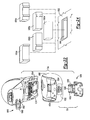
- the battery pack 74 may be coupled to the motor 70 by way of an integrated snap connector 108 as illustrated in Figures 36 through 39 .
- the snap connector 108 may have a first portion 108a that may be integrated with the motor 70 and a second portion 108b that may be integrated with the battery pack 74.
- the first portion 108a may include a circuit board 110 with a plurality of terminals, such as blade-type male terminals 112.
- the circuit board 110 may include all of the integrated circuits and solid state components that are employed for controlling the distribution of electrical power from the battery pack 74 to the motor 70, as well as for controlling the charging of the battery pack 74 (e.g., timers).
- the second portion 108b may include a plurality of mating terminals, such as blade receiving terminals 114, that matingly engage the terminals of the first portion 108a.
- the blade receiving terminals 114 slidably receive the blade-type male terminals 112 to permit the motor assembly 30 to be coupled to the battery pack 74 prior to their installation to the housing 32.
- the battery pack 74 may further include a housing 120 having a pair of engagement features 122 that co-engage mating features 124 ( Fig. 11 ) to permit the battery pack 74 to be coupled to the housing 32 without separate fasteners, etc.
- the engagement features 122 are tabs and the mating features 124 are slots that are configured to receive an associated one of the tabs to thereby fixedly but removably couple the battery pack 74 to the housing 32.
- At least one of the tabs may be a cross-tab (i.e., a tab with two portions that are skewed to one another) that is configured to engage an associated mating feature 124 in a manner that inhibits vertical and horizontal movement of the cross-tab relative to the associated mating feature 124.
- the structure into which the cross-tab is received defines a cross-slot (i.e., a slot with two portions for receiving the two portions of the cross-tab), but as those skilled in the art will appreciate from this disclosure, one portion of the cross-tab may be disposed in the slot while the other portion of the cross-tab abuts an end of the structure that defines the slot.
- the housing 120 may house a pair of charging terminals 126 that may be configured to extend through the housing 32 so as to be accessible by the recharging base 75 ( Fig. 1 ) when the vacuum 10a is coupled thereto.
- the power switch 76 may include a conventional slide switch 76a that selectively enables or disables the transmission of electric power therethrough to close or open the electrical circuit between the batteries 100 and the motor 70.
- the slide switch 76a may be fixedly coupled to the circuit board 110 in the particular example provided and employed to move contacts into and out of electrical connection with terminals on the circuit board 110.
- the housing 32 of the particular embodiment provided may include a pair of housing shells 150a and 150b and an exhaust deflector 154.
- the housing shells 150a and 150b may be configured to be coupled together in a conventional and well known manner to define a switch mounting structure 160, a switch aperture 162, a latch mounting structure 164, the retaining tab 42 and a handle 168.
- the switch mounting structure 160 may be conventionally configured to receive therein and support the power switch 76 of the motor assembly 30 such that the power switch 76 extends through the switch aperture 162 so as to be actuate-able by the user of the vacuum 10a.
- the latch mounting structure 164 may be configured to receive therein and support a conventional latch mechanism 40 having a latch member 170 for engaging the securing aperture 56a in the housing structure 52 of the dirt cup assembly 12 and a spring (not shown) for biasing the latch member 170 upwardly relative to the housing 32.
- the retaining tab 42 extends outwardly from the housing 32 and defines an abutting wall 174.
- the retaining tab 42 may be configured to project through the securing aperture 56b when the dirt cup assembly 12 is coupled to the housing assembly 14 to permit the abutting wall 174 to cooperate with the rear edge of the securing aperture 56b to thereby limit forward movement of the dirt cup assembly 12 relative to the housing assembly 14.
- the handle 168 is integrally formed with the housing shells 150a and 150b and may extend between the forward and rearward portions of the housing 32 and above the body of the housing 32 to define therebetween a handle aperture 180 that is sized to receive the hand of the user of the vacuum 10a.
- the handle 168 may be otherwise positioned and/or a discrete component that is joined or fastened to the remainder of the housing 32 in a known manner.
- the housing shell 150a includes a wall member 186 that may define a front wall 188, a central cavity 196, an exhaust cavity 200 and a recessed area 202 through which an elliptical through-hole 204 is formed.
- the wall member 186 may also define a motor mount 206 and a hub mount 208, both of which being disposed in the central cavity 196.
- the motor mount 206 may include first and second mount portions 206a and 206b, respectively, that are employed to fixedly couple the motor 70 to the housing 32.
- the motor mount 206 may be configured to receive the motor 70 in a snap-fit manner so that discrete fasteners and the like are not required.
- the hub mount 208 may include structure which, in association with the fan housing 92 in the example provided, serves to maintain the filter cleaning system 36 in a desired location along a longitudinal axis of the vacuum 10a relative to the filter system 34.
- the hub mount 208 includes first and second bearing portions 208a and 208b, respectively, which are axially spaced apart along an axis that is coincident with a rotational axis of the motor 70.
- the first bearing portion 208a may be semi-circular in shape so as to form a circular aperture when the housing shells 150a, 150b are coupled to one another.
- the second bearing portion 208b may include a rear wall 210 that may be generally transverse to the rotational axis of the motor 70.
- the fan housing 92 may form the inlet aperture 94 and one or more discharge apertures 96 through which air is introduced and discharged, respectively, from the fan assembly 72.
- the fan housing 92 forms a volute that terminates at the discharge aperture 96.
- the flow channel 98 may serve as a fluid conduit which couples the discharge aperture 96 with the exhaust cavity 200.
- the exhaust deflector 154 may include a frame 270 and a plurality of flow guiding vanes 272 that are set into the frame 270 and fixedly coupled thereto.
- the flow guiding vanes 272 of the particular embodiment illustrated are shaped so as to direct the air exiting the exhaust cavity 200 both downwardly and rearwardly.
- the frame 270 of the exhaust deflector 154 may extend upwardly of the flow guiding vanes 272 to create a pocket 276 into which may be fitted an optional exhaust filter 280.
- the exhaust filter 280 operates to filter the air that exits the exhaust cavity 200 and thereby prevents fine dust particles from being expelled from the vacuum 10a.
- the exhaust filter 280 may be formed from a non-woven mesh fabric so as to be washable should it become undesirably dirty or clogged. Those skilled in the art will appreciate from this disclosure, however, that the exhaust filter 280 may be formed from another washable filter media or may alternately be a disposable type filter (e.g., paper).
- the exhaust filter may be configured to provide HEPA (high efficiency particulate air) filtration or ULPA (ultra low penetration air) filtration.
- HEPA high efficiency particulate air
- ULPA ultra low penetration air
- the frame 270 may also include a pair of trunnions 284 and a pair of clip structures 286.
- the trunnions 284 permit the exhaust deflector 154 to be pivotably coupled to the housing 32. More specifically, each of the housing shells 150a and 150b may include a recess (not specifically shown) for receiving an associated one of the trunnions 284.
- Each trunnion 284 is illustrated as being coupled to a portion of the frame 270 that may be deflected laterally inward (i.e., toward the centerline of the exhaust deflector 154) so that the trunnions 284 may be installed to their respective recess when the housing shells 150a and 150b are coupled to one another.
- the exhaust deflector 154 may be pivoted between a closed position, wherein the rear surface of the exhaust deflector 154 covers the exhaust cavity 200, and an open position, wherein the exhaust deflector 154 substantially clears the exhaust cavity 200.
- the clip structures 286 are configured to resiliently deflect in response to the application of a modest force to the exhaust deflector 154 to permit the exhaust deflector 154 to be secured to or released from the wall member 186 when the exhaust deflector 154 is moved into or out of the closed position.
- engagement of the clip structures 286 to the wall member 186 effectively maintains the exhaust deflector 154 in the closed position.
- features such as recesses or tabs 288 may be formed into the wall member 186 to serve as points that enhance or improve the ability of the clip structures 286 to engage the wall member 186.
- the top of the frame 270 of the exhaust deflector 154 may be arcuately shaped to define a finger grip 290 that is configured to receive the thumb or finger of the user of the vacuum 10a so that the thumb or finger may be employed to move the exhaust deflector 154 out of the closed position.
- the finger grip 290 may include a gripping feature, such as a raised lip, that permits the user to pry downwardly and outwardly on the exhaust deflector 154 with their thumb or finger to thereby disengage the clip structures 286 from the wall member 186.
- the filter cleaning system 36 may include a cleaning wheel 300 that housed by the housing 32.
- the cleaning wheel 300 may be generally hollow and may include a gripping portion 302, a hub portion 304, a filter drive portion 306 and a filter engagement portion 308.
- the gripping portion 302 may be an annular ring that may be coupled to the rearward side of the hub portion 304 and which may include a plurality of circumferentially spaced apart recesses 310.
- the hub portion 304 may define a bearing surface 312 that may be journally supported by the housing 32.
- the filter drive portion 306 may be formed on a wall 314 that is coupled to the hub portion 304 generally transverse to the bearing surface 312.
- the filter drive portion 306 includes a plurality of radially extending drive tabs 316 that are circumferentially spaced apart from one another and collectively oriented concentric with the bearing surface 312.
- the filter engagement portion 308, through frictional engagement or other engagement with the primary filter 414, may also serve in whole or in part as the filter drive portion 306.
- the filter engagement portion 308 may be an elongated annular structure that may extend forwardly from the wall 314 of the filter drive portion 306.
- the cleaning wheel 300 may also include a grille 320 which inhibits the passage of relatively large objects from passing through the cleaning wheel 300 and contacting the impeller 90.
- the cleaning wheel 300 may be installed over the fan housing 92 prior to the installation of the motor 70 and fan assembly 72 to the housing 32, thereby permitting these components to be collectively assembled to one of the housing shells (e.g., housing shell 150a) substantially simultaneously.
- the cleaning wheel 300 may be positioned relative to the housing 32 such that gripping portion 302 partially extends through the elliptical through-holes 204 in the recessed areas 202 of the housing 32 as shown in Figure 17 .
- movement of the cleaning wheel 300 in an axial direction along the rotational axis of the motor 70 may be limited through contact between the gripping portion 302 and housing 32 along the perimeter of the elliptical through-holes 204.
- contact with the fan housing 92 and the rear wall 210 of the second bearing portion 208b ( Figure 11 ) may be employed to limit movement of the cleaning wheel 300 axially along the rotational axis of the motor 70.
- the first and second bearing portions 208a and 208b of the hub mount 208 cooperate with the bearing surface 312 to limit the movement of the cleaning wheel 300 vertically and horizontally relative to the rotational axis of the motor 70, but permit the cleaning wheel to be rotated about the rotational axis of the motor 70.
- the recesses 310 in the gripping portion are specifically configured to be gripped by the thumb and/or fingers of a user of the vacuum 10a to rotate the cleaning wheel 300.
- the filter system 34 may include an intake filter 400 and the above-discussed optional exhaust filter 280.
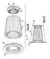
- the intake filter 400 may include a prefilter 412 and a primary filter 414.
- the prefilter 412 may include a filter flange 420, a prefilter body 422 and a securing means 424 for releasably securing the prefilter 412 to the housing 32.
- the filter flange 420 may extend radially outwardly from the prefilter body 422 and may be configured to abut the front face 188 of the housing 32.
- the filter flange 420 may be unitarily formed with the remainder of the prefilter 412 from a material that is structural, such as polyethylene or polpropylene. Those skilled in the art will appreciate, however, that the filter flange 420 could alternatively include a resilient band of material (not shown) that is coupled to the remainder of the filter flange 420, via a mechanical connection, adhesives or overmolding, and employed to sealingly engage at least one of the housing 32 and the dirt cup 20.
- the prefilter body 422 may have a truncated cone shape, with a front wall 430 and a side wall 432 that has a plurality of filtering apertures 434 formed therethrough.
- the filtering apertures 434 may be sized to prevent relatively coarse dirt and debris from contacting the primary filter 414 ( Fig. 3 ).
- the filtering apertures 434 are about 0.020 inch (0.5 mm) to about 0.040 inch (1.0 mm) in diameter.
- one or more ribs 436 are formed on the interior surface 438 of the side wall 432. The ribs 436 will be discussed in greater detail, below.
- any appropriate means may be employed to removably couple the filter flange 420 to one or both of the housing 32 and the dirt cup 20.
- the securing means 424 will not automatically detach from the housing 32 when the dirt cup 20 is removed from the housing 32.
- the securing means 424 is illustrated in Figure 18 to include a plurality of holes 440 that are configured to receive therethrough corresponding pegs 442 that extend from the front face 188 of the housing 32 as illustrated in Figure 16 .
- the holes 440 may be shaped to directly correspond to the shape of the pegs 442, but in the example illustrated, include first and second portions 440a and 440b, respectively, that intersect one another.
- the first portion 440a is relatively large and configured to receive therethrough an associated peg 442, which is illustrated in Figure 10 to include a relatively large head portion 442a and a somewhat smaller body portion 442b.
- the second portion 440b is configured only to receive therethrough the body portion 442b of the associated peg 442.
- the prefilter 412 may be rotated to position the body portion 442b of the pegs 442 into the second portion 440b of the holes 440.
- the filter flange 420 will remain attached to the housing 32 when the dirt cup 20 is removed, unless the filter flange 420 is rotated to align the pegs 442 with the first portion 440a of the holes 440.
- the securing means 424 may include a resilient finger 440c that contacts the body portion 442b of an associated peg 442 to inhibit rotation of the filter flange 420 unless a force in excess of a predetermined force has been applied to rotate the filter flange 420 in a desired rotational direction relative to the housing 32.
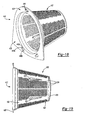
- the primary filter 414 may have a filter body 450 with first and second seal portions 452 and 454, respectively, disposed on opposite sides thereof.
- the filter body 450 may have a shape that is similar to that of the prefilter body 422 ( Fig. 19 ) and in the example provided, is illustrated to have a truncated cone shape.
- the filter body 450 may be formed from any appropriate filter media, such as paper, plastic or fabric and is preferably formed with a plurality of pleats 460.
- the filter media is wear resistant or includes a wear resistant outer layer 462.
- the filter body 450 is preferably formed from a filter media that provides HEPA or ULPA filtration.
- One such suitable filter media is manufactured by W. L. Gore & Associates, a Delaware Corporation having a place of business in Elkton, Maryland.
- the pleats 460 are formed such that their outer ends or peaks 464 lie along a straight line that intersects the axis of a theoretical cone (not shown) that includes the peak 464 of each pleat 460 on the filter body 450.
- the pleats 460 may be formed such that their peaks 464 are straight but skewed to the axis of the theoretical cone or generally helical in shape.
- the pleats 460 should be formed relative to the theoretical cone in a manner that is consistent with the ribs 436 on the interior surface 438 of the filter housing 432.
- the first seal portion 452 which is coupled to the smaller end of the filter body 450, may be a plate-like structure that is formed from a suitable material and is sealingly bonded to a lower end of the filter body 450.
- the first seal portion 452 may be wholly or partially formed from an appropriate filter material, such as the material from which the filter body 450 is manufactured, and bonded or otherwise sealingly coupled to the filter body 450.
- the second seal portion 454 may be an annular flange that may be sealingly bonded to an upper end of the filter body 450.
- the second seal portion 454 may include a body 470 that defines a receiving aperture 472, a primary seal 474 which is disposed about the perimeter of the receiving aperture 472 and sized to sealingly engage the seal engaging portion 308 of the cleaning wheel 300 ( Fig. 15 ), a secondary seal 476 that sealingly engages the interior surface 438 of the prefilter body 422 of the prefilter 412, and a plurality of drive tabs 478.
- the drive tabs 478 which extend radially outward and are circumferentially spaced apart from one another, are configured to engage the drive tabs 316 that are formed on the filter drive portion 306 of the cleaning wheel 300.
- the prefilter 412 may be positioned over the primary filter 414 such that the first portion 440a of the through-holes 204 in the filter flange 420 are aligned to the pegs 442 on the housing 32.
- the prefilter 412 may be urged toward the housing 32 such that the pegs 442 are fitted through the through-holes 204 and thereafter the prefilter 412 is rotated to position the pegs 442 within the second portion 440b of the through-holes 204.
- the prefilter locating tabs 58 urge the filter flange 420 rearwardly toward the front face 188 of the housing 32 so that the secondary seal 476 sealingly engages the prefilter body 422 of the prefilter 412.
- the primary filter 414 may be formed in various other manners.
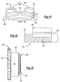
- the primary filter 414 may include a pair of discretely formed, caps 480a and 480b as illustrated in Figures 40 and 41 .
- the cap 480a may be generally cup shaped, with a closed top 482 and a side wall 484 with a plurality of teeth 486 formed about the inside perimeter of the side wall 484.
- the cap 480b may be an annular ring that similarly includes a plurality of teeth 488 formed about its inside perimeter.
- the caps 480a, 480b may be secured to the opposite ends of the filter body 450 through an adhesive, heat staking or sonic welding, for example, so that the teeth 486 and 488 of the caps 480a and 480b meshingly engage the pleats 460 of the filter media.
- the first seal portion 452 may be integrally formed with, molded onto or bonded to the annular cap 480b.
- the second seal portion 454 is optional in this embodiment, as the cap 480a may be formed with a closed configuration, rather than the annular shape of the cap 480b.
- Figures 42 and 43 is similar to that discussed above in that it likewise employs a pair of discretely formed caps 480c and 480d. However, the teeth 486 and 488 are formed on the exterior surfaces of the caps 480c and 480d so as to meshingly engage the pleats 460 from the interior of the filter body 450.
- the embodiment of Figures 44 and 45 employs a pair of ring sets 490 and 492.
- the ring set 490 may include an outer ring 490a, which may be similar to the cap 480a, and an inner ring 490b, which may be similar to the cap 480c.
- the outer and inner rings 490a and 490b are assembled to the filter body 450 such that the filter media is sandwiched therebetween and secured to the filter body 450 and/or to one another via an adhesive, heat staking or sonic welding, for example.
- the ring set 492 includes an outer ring 492a, which may be similar to the cap 480b, and an inner ring 492b, which may be similar to the cap 480d.
- the outer and inner rings 492a and 492b are assembled to the filter body 450 such that the filter media is sandwiched therebetween.
- the outer and inner rings 492a and 492b are secured to the filter body 450 and/or to one another via an adhesive, heat staking or sonic welding, for example.
- the fan assembly 72 expels air from the fan housing 92 which creates a negative pressure differential relative to atmospheric conditions and causes a dirt and debris laden air flow to rush into the dirt cup 20 through the inlet port 54.
- the elbow 22 When coupled to the inlet port 54, the elbow 22 directs the dirt and debris laden air that is flowing through the inlet port 54 toward the interior wall of the dirt cup 20, causing the dirt and debris laden air to swirl about the interior of the dirt cup.
- the outlet 500 of the elbow 22 is configured to direct the dirt and debris laden air flow in a direction to the side and rear of the dirt cup 20.
- the elbow 22 may be configured to direct the dirt and debris laden air flow in a direction generally transverse to the inlet port 54, that the outlet 500 of the elbow 22 may or may not lie in the same "plane" as the inlet port 54 (i.e., the centerline of the elbow 22 at the outlet 500 may or may not lie in a plane that is contains the centerline of the inlet port 54) and that any portion of the elbow 22 between the outlet 22 and the inlet port 54 may be formed with a desired shape (e.g., helical) to enhance the swirling effect produced by the elbow 22 and the dirt cup 20.
- a desired shape e.g., helical
- the swirling effect may be so strong as to create centrifugal force that causes the dirt and debris to move outwardly toward and collect against the dirt cup 20.
- the swirling effect may also slow the collection of dirt and debris on the prefilter 412 and the primary filter 414 to thereby provide improved efficiency of the vacuum 10a. Improved efficiency is particularly important with cordless vacuums, as it permits extended operation on a given battery charge.
- the elbow 22 may be removable from the inlet port 54.
- the vacuum 10a may be additionally and further maintained in an efficient state by rotating the cleaning wheel 300 as needed or at a desired interval when the impeller 90 is not rotating to at least partially clear accumulated dirt and debris from the pleats 460 of the primary filter 414. More specifically, as the primary filter may be coupled to the cleaning wheel 300, rotation of the cleaning wheel 300 causes contact between the ribs 436 and an associated set of the pleats 460 which may deflect the pleats 460 and vibrate the pleats 460 after the pleat 460 has rotated past the rib 436. The force of the impact, the deflection of the pleat 460 and its subsequent vibration may cooperate to dislodge particles of dirt and debris from both the prefilter 412 and the primary filter 414.
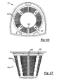
- the prefilter 412 may be constructed with one or more apertures 5000 as shown in Figures 46 and 47 .
- the apertures 5000 are relatively larger than the filtering apertures 434 so that dirt and debris that are dislodged from the primary filter 414 ( Fig. 20 ) during cleaning, e.g., rotation of the cleaning wheel 300 ( Fig. 15 ), may more readily fall through the prefilter body 422 and collect in the dirt cup 20 ( Fig. 1 ).
- the prefilter body 422 is constructed such that at least a portion of the ribs 436 are shifted along the longitudinal axis of the prefilter body 422. In the particular example provided, each of the ribs 436 is shifted so that no two ribs 436 contact the same area of the pleats 460 ( Fig. 20 ).
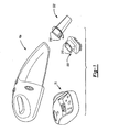
- the tool set 10b may include a brush tool 500 and a crevice tool 502 that may be fixedly but removably engaged to the front end of the inlet port 54 via a friction fit.
- the brush tool 500 and crevice tool 502 each employ a body portion 504 having first and second portions 506 and 508 with a U-shaped aperture 510 formed therebetween.
- the U-shaped aperture 510 permits a relatively large degree of flexure between the first and second portions 506 and 508 so as to ensure high quality friction fit and associated seal between the body portion 504 and inlet port 54 of the dirt cup 20.
- the brush tool 500 may be stored in a cavity 518 formed in the rear of the housing 32, while the crevice tool 502 may be coupled to a bottom face 520 of the housing 32.
- One or more resilient clips 522 may be employed to retain the particular accessory to the housing 32.
- the recharging base 75 is illustrated in association with the vacuum 10a.
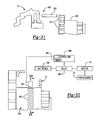
- the recharging base 75 may include a base 1000, a charging circuit 1002, a pair of terminals 1004 and a key 1006.
- the base 1000 may be a molded structure and may be configured to slidably receive the vacuum 10a such that a pair of mating terminals 1014 and a mating key 1016 matingly engage the terminals 1004 and the key 1006, respectively.
- the charging circuit 1002 may be configured in a conventional and well known manner to receive electrical power from a source of A.C. power and provide a source of D.C. power of a predetermined voltage to the terminals 1004.
- the terminals 1004 which may be mounted to the base 1000, may extend outwardly from the base 1000 so as to contact associated ones of the mating terminals 1014 when the vacuum 10a is fully received into the base 1000. As the terminals 1014 are electrically coupled to the battery pack 74, contact between the terminals 1004 and 1014 permits electrical energy to be transmitted from the charging circuit 1002 to the batteries 100.
- the key 1006 and the mating key 1016 coordinate with one another to permit the base 1000 to fully receive the vacuum 10a.
- the key 1006 includes a pedestal 1028, a flange 1030 and optionally one or more engagement tabs 1032, while the mating key 1016 includes a receiver 1040.
- the pedestal 1028 of the key 1006 may be coupled to the base 1000 in any conventional manner, including for example, threaded fasteners and/or features that are integrally formed onto and/or into the pedestal 1028 and base 1000 that permit the pedestal 1028 and the base 1000 to be engaged to one another in a snap-fit manner.
- the flange 1030 may be coupled to the pedestal 1028, extending upwardly therefrom so as to protrude from a corresponding aperture 1036 in the base 1000 when the key 1006 and the base 1000 are coupled to one another. If employed, the engagement tabs 1032 extend from the flange 1030 in the example provided.
- the receiver 1040 may be coupled to the housing 32 in any conventional manner, including for example, threaded fasteners and/or features that are integrally formed onto and/or into the receiver 1040 and housing 32 that permit the receiver 1040 and the housing 32 to be engaged to one another in a snap-fit manner.
- the receiver 1040 of the mating key 1016 may optionally include one or more slots 1042 for receiving the engagement tabs 1032.
- the engagement tabs 1032 and slots 1042 are positioned such that they must engage one another before the terminals 1020 and 1022 may contact one another.
- the vacuum 10a has been described thus far as including slots 1042 for receiving engagement tabs 1032 that are associated with the recharging base 75, the slots 1042 and engagement tabs 1032 may alternatively be associated with the recharging base 75 and the vacuum 10a, respectively.
- FIG. 23 the interchangeable nature of the charging system of the present invention is illustrated. Specifically, several terminal block (1004) and key (i.e., 1006a, 1006b, 1006c, 1006d, and 1006e) combinations are illustrated as being interchangeable with the base 1000, while several receivers (1040a, 1040b, 1040c, 1040d, and 1040e) are illustrated in association with the vacuum 10a.
- the injection molds for each of the key and the receiver employ exchangeable tooling segments that permit the molds to be readily converted so that they may be employed to form each of the various key configurations and receiver configurations.
- five tooling segments 1050a, 1050b, 1050c, 1050d and 1050e are employed in conjunction with a base mold 1052 to produce each of the receiver combinations.
- One especially significant aspect of providing various key and mating key combinations is the ability to provide a family of similar vacuums having different batteries (i.e., different voltages) yet which utilize as many common components as possible.
- the various key and mating key combinations are employed to "key" a particular vacuum to a particular recharging base so as to prevent a vacuum from being coupled to a recharging base having a charging circuit that provides a charging voltage in excess of that which the batteries of the vacuum are designed to be charged.
- a family of hand-held cordless vacuums is generally indicated by reference numeral 2000.
- the family of vacuums 2000 includes vacuums 2002a, 2004a, 2006a, 2008a and 2010a, which are associated with recharging bases 2002b, 2004b, 2006b, 2008b and 2010b, respectively.
- the vacuums 2002a, 2004a and 2006a are generally identical to vacuum 10a and differ from one another only in the design charging voltage of their respective battery packs 74.
- the vacuum 2002a may have a design charging voltage of 14.4 volts
- the vacuum 2004a may have a design charging voltage of 12 volts
- the vacuum 2006a may have a design charging voltage of 9.6 volts.
- the vacuums 2008a and 2010a are similar to the vacuum 10a ( Fig.
- the recharging bases 2002b, 2004b, 2006b, 2008b and 2010b are generally identical to the recharging base 75 ( Fig. 1 ) and differ from one another only in the charging voltage that they output.
- the recharging bases i.e., the keys
- the recharging bases may be configured so that they will only engage one vacuum (i.e., mating key).
- a recharging base i.e., key
- any member of the family of vacuums 2000 may be engaged to the recharging base 2010b.
- the vacuum 2004a may also be engaged to the charging bases 2004b, 2006b, and 2008b.
- the vacuum 10c may employ one or more vanes to swirl the incoming dirt and debris laden air flow as shown in Figures 26 and 27 .
- the vacuum 10c is identical to the vacuum 10a described above, except that the elbow 22 ( Fig. 3 ) is not employed and a prefilter 412c has been substituted for the prefilter 412.
- the prefilter 412c is substantially similar to the prefilter 412, except for the inclusion of a plurality of flow guiding vanes 600 on the front wall 430c of the prefilter body 422c.
- the flow guiding vanes 600 are disposed axially in-line with the inlet port 54c such that the axially directed incoming dirt and debris laden air flow is turned by the flow guiding vanes 600 outwardly toward the interior surface of the wall of the dirt cup 20c.
- the flow guiding vanes 600 may be configured aggressively, wherein the entire flow is turned outwardly at the interior surface of the dirt cup 20c, or somewhat less aggressively, wherein the flow is turned outwardly but retains a portion of its original axial velocity.
- vanes 600d for swirling the incoming dirt and debris laden air flow may be additionally or alternatively formed on another surface, such as the exterior surface 620 of the side wall 432d of the prefilter 412d, as illustrated in Figure 28 .
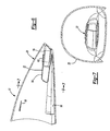
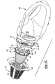
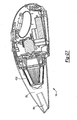
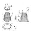
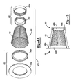
- the vacuum 10e may be configured as is shown in Figures 29 and 30 .
- the housing assembly 14e defines a filter recess 700 into which the filter system 34e is disposed.
- the filter system 34e includes a hat-shaped prefilter 412e and a hat-shaped primary filter 414e.
- the prefilter 412e includes a filter flange 420e and a prefilter body 422e, while the primary filter 414e includes a filter flange 710 and a filter body 712.
- a nozzle 720 is pivotally coupled to the housing assembly 14e and unlike the dirt cup 20 of Figure 1 , the nozzle 720 has no capacity for the storage of the dirt and debris that is drawn up by the vacuum 10e.
- the nozzle 720 includes an outlet 730 that directs an incoming flow of dirt and debris laden air tangentially into the prefilter 412e, thereby generating a swirling effect that tends to reduce the accumulation of dirt and debris against the side wall 432e of the prefilter 412e.
- This configuration is highly advantageous in that it permits the user to not only perform vacuuming operations with a single hand, but also to empty the vacuum 10e of dirt and debris with a single hand. More specifically, the user need only access the latch release 38 to unlatch the nozzle 720 from the housing assembly 14e to permit the nozzle 720 to pivot into the open condition.
- a detent (not specifically shown) may be employed to retain the nozzle 720 in the open condition. The user need only grasp the handle 168 of the housing assembly 14e and overturn the vacuum 10e to empty the contents of the prefilter 412e.
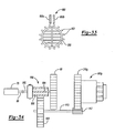
- a lock-out member 802 When the power switch 76 is activated, a lock-out member 802 translates into locking engagement with one of the circumferentially spaced apart recesses 310 in the gripping portion 302 of the cleaning wheel 300 to prevent the cleaning wheel 300 from being rotated.
- a sensor 850 is employed to detect the rotation of the cleaning wheel 300 relative to the housing 32 and generate a sensor signal in response thereto.
- the sensor 850 includes a pair of spaced apart contacts 850a and 850b which are normally not in contact with one another but which are urged into electrical contact with one another by actuating features 852 that are formed on the cleaning wheel 300.
- a controller 860 is employed to inhibit the flow of electricity from the batteries 100 to the motor 70 to thereby deactivate the fan assembly 72.
- the controller 860 employs a conventional relay 862 to inhibit the flow of electricity from the batteries 100 to the motor 70.
- the controller 860 may include a timer 864 which maintains the motor 70 in a deactivated state for a predetermined amount of time after receipt of the sensor signal.
- the cleaning wheel is illustrated to be driven by a motor rather than manually operated.
- a clutch 900 having an input shaft 902, which is coupled to the output shaft 88 of the motor 70, a first output shaft 904, to which the impeller 90 is coupled for rotation therewith, and a second output shaft 906, which is concentric with the first output shaft 904, which is meshingly engaged with an idler gear 908.
- a shaft 910 couples an output pinion 912, which is meshingly engaged with teeth 310g formed on the cleaning wheel 300g, for rotation with the idler gear 908.
- the clutch 900 is normally operable in first condition, wherein rotary power is transmitted to the first output shaft 904 but not the second output shaft 906, and a second condition, wherein rotary power is transmitted to the second output shaft 906 but not the first output shaft 904.
- the clutch 900 is preferably electronically controlled, so that the user need only press a button to change the condition of the clutch 900 from the first condition to the second condition (such as by translating the power switch 76 ( Fig. 3 ) in a direction opposite that which is normally employed to actuate the vacuum 10a).
- the clutch 900 is normally operable in the first condition, so that when the button is released, the clutch 900 will revert to the first condition.
- a second motor 950 is employed to rotate the cleaning wheel 300.
Abstract
Description
- The present invention generally relates to hand-held portable vacuum cleaners and improvements thereto.
- Typically, hand-held portable vacuum cleaners employ a motor that is powered by either a main supply of electricity (i.e., a source of alternating current power) or a battery pack, which may be rechargeable, to drive an impeller. Rotation of the impeller generates an air flow which entrains therein dirt and debris which enter the vacuum cleaner via an inlet. One or more filters may be employed to retain the dirt and debris within the vacuum.
- One problem with such vacuum cleaners concerns the relatively rapid rate with which the efficiency and performance of such vacuum cleaners may deteriorate. Specifically, the use of such vacuums to collect relatively small sized particles can rapidly load the filter and substantially reduce the amount of air that passes therethrough. When filter loading is encountered in the known hand vacuum configurations, the user must disassemble the vacuum, remove the filter, clean (or dispose of and replace) the filter and replace the filter. In some situations, the user may be reluctant to perform the tasks of removing and cleaning the filter due to the unwholesomeness of the material that has accumulated on the filter. In situations where the filter is heavily loaded, the vacuum will have a relatively low efficiency and consequently, vacuuming tasks will take longer, the vacuum will experience greater wear, and if battery powered, the user will be able to perform relatively fewer vacuuming tasks per charge.
- An example of a vacuum cleaner of the prior art which demonstrates some of the problems set out above is disclosed in
US5025529 . - According to an aspect of the present invention, there is provided a hand-held portable vacuum comprising the features of
claim 1. - In one form, the present teachings provide a hand-held portable vacuum having a housing, an impeller that is at least partially disposed in the housing, a dirt cup and a HEPA filter. The dirt cup, which is removably attached to the housing, includes an inlet and defines a container for storage of dirt and debris therein. The HEPA filter is disposed between the impeller and the inlet.
- In another form, the present teachings provide provides a method for filtering a dirt and debris laden air flow. The method includes: providing a hand-held vacuum with a housing, an impeller, an inlet, a container and a primary filter, the housing including a handle that permits a user to employ the hand-held vacuum for vacuuming with a single hand, the impeller being disposed within the housing, the inlet being configured to receive the dirt and debris laden air flow therethrough, the container being configured to retain dirt and debris removed from the dirt and debris laden air flow and the primary filter being disposed between the impeller and the inlet; rotating the impeller to generate the dirt and debris laden air flow; and swirling the dirt and debris laden air flow about the interior of the container.
- According to the invention there is provided a hand-held portable vacuum including a housing with a handle, a dirt cup, an impeller at least partially disposed in the housing, a filter and a filter cleaning device. The dirt cup, which is removably attached to the housing, has an inlet and defines a container for storage of dirt and debris therein. The filter, which is disposed between the impeller and the inlet, is formed with a plurality of pleats. The filter cleaning device is coupled to at least one of the housing and the dirt cup and includes at least one rib and a hub. The hub is coupled to one of the filter and the rib and configured to rotate the one of the filter and the rib about the other one of the filter to generate contact between the rib and the filter to at least partially dislodge accumulated dirt and debris from the pleats.
- In a further form, the present teachings provide a hand-held portable vacuum including a housing with a handle, a dirt cup, an impeller, a filter and a means for swirling the dirt and debris laden air in the dirt cup. The dirt cup, which is removably attached to the housing, has an inlet and defining a container for storage of dirt and debris therein. The impeller is at least partially disposed in the housing and operable for generating an air flow that flows through the inlet. The filter is disposed between the impeller and the inlet.
- Further areas of applicability of the present teachings will become apparent from the detailed description provided hereinafter. It should be understood that the detailed description and specific examples, while indicating the preferred embodiment of the invention, are intended for purposes of illustration only and are not intended to limit the scope of the invention.
- Additional advantages and features of the present invention will become apparent from the subsequent description and the appended claims, taken in conjunction with the accompanying drawings, wherein:
-
Figure 1 is a perspective view of a vacuum kit constructed in accordance with the teachings of the present invention; -
Figure 2 is a side elevation view of a portion of the vacuum kit ofFigure 1 illustrating the vacuum in greater detail; -
Figure 3 is a longitudinal section view of the vacuum ofFigure 2 ; -
Figure 4 is a perspective view of a portion of the vacuum ofFigure 2 illustrating the dirt cup in greater detail; -
Figure 5 is a longitudinal section view of the dirt cup ofFigure 4 ; -
Figure 6 is a longitudinal section view of a portion of the vacuum ofFigure 2 illustrating the dirt cup assembly in greater detail; -
Figure 7 is a sectional view taken along the line 7-7 ofFigure 6 ; -
Figure 8 is a perspective view illustrating the interior of the dirt cup assembly; -
Figure 9 is a perspective view of a portion of the dirt cup assembly illustrating the elbow in greater detail; -
Figure 10 is a top view of a portion of the vacuum ofFigure 2 illustrating the housing assembly in greater detail; -
Figure 11 is a side elevation view of a portion of the housing assembly illustrating a housing shell in greater detail; -
Figure 12 is an exploded perspective view of a portion of the housing assembly; -
Figure 13 is a elevation view of a portion of the vacuum ofFigure 2 illustrating the exhaust grille in greater detail; -
Figure 14 is section view taken along the line 14-14 ofFigure 13 ; -
Figure 15 is a side elevation view of a portion of the vacuum ofFigure 2 illustrating the cleaning wheel in greater detail; -
Figure 16 is a front elevation view of the housing assembly; -
Figure 17 is a side elevation view of the housing assembly; -
Figure 18 is a perspective view of a portion of the housing assembly illustrating the prefilter in greater detail; -
Figure 19 is a longitudinal section view of the prefilter; -
Figure 20 is a longitudinal section view of the primary filter; -
Figure 21 is a longitudinal section view of a portion of the housing assembly illustrating the second seal portion of the primary filter in sealing engagement with the prefilter; -
Figure 22 is an exploded perspective view of the vacuum and recharging base ofFigure 1 ; -
Figure 23 is an exploded perspective view of the vacuum and recharging base illustrating one means by which the vacuum and recharging base may be keyed to one another; -
Figure 24 is a schematic illustration of a portion of an injection mold for forming the mating key that is associated with the vacuum in the example provided; -
Figure 25 is a perspective view of a family of vacuums and recharging bases constructed in accordance with the teachings of the present invention; -
Figure 26 is a perspective view of an alternately constructed prefilter; -
Figure 27 is a longitudinal section view similar to that ofFigure 3 but illustrating the prefilter ofFigure 26 ; -
Figure 28 is a perspective view of another alternately constructed prefilter; -
Figure 29 is a perspective view of an alternately constructed vacuum; -
Figure 30 is an exploded perspective view of the vacuum ofFigure 29 ; -
Figure 31 is a partial longitudinal section view of another alternately constructed vacuum illustrating a lock-out device for inhibiting the operation of the cleaning wheel; -
Figure 32 is a schematic illustration of another alternately constructed vacuum illustrating an electronic lock-out device for inhibiting the operation of the motor when the cleaning wheel is rotated; -
Figure 33 is a sectional view taken along the line 33-33 ofFigure 32 ; -
Figure 34 is a schematic illustration of yet another alternately constructed vacuum illustrating a drive system for rotating the cleaning wheel under a source of power; -
Figure 35 is a schematic illustration of still another alternately constructed vacuum illustrating another drive system for rotating the cleaning wheel under a source of power; -
Figure 36 is an exploded perspective view of a portion of the vacuum ofFigure 2 illustrating the battery pack and motor assembly in greater detail; -
Figure 37 is another exploded perspective view of the battery pack and motor assembly; -
Figure 38 is an exploded side elevation view of the battery pack and motor assembly; -
Figure 39 is a bottom plan view of the battery pack as coupled to the motor assembly; -
Figure 40 is an exploded perspective view of an alternately constructed primary filter; -
Figure 41 is a longitudinal section view of the primary filter ofFigure 40 ; -
Figure 42 is an exploded perspective view of another alternately constructed primary filter; -
Figure 43 is a longitudinal section view of the primary filter ofFigure 42 ; -
Figure 44 is an exploded perspective view of yet another alternately constructed primary filter; -
Figure 45 is a longitudinal section view of the primary filter ofFigure 44 ; -
Figure 46 is a rear view of another prefilter constructed in accordance with the teachings of the present invention; -
Figure 47 is a bottom view of the prefilter ofFigure 46 ; and -
Figure 48 is a perspective view of yet another prefilter constructed in accordance with the teachings of the present invention. - With reference to
Figure 1 of the drawings, a vacuum kit constructed in accordance with the teachings of the present invention is generally indicated byreference numeral 10. Thevacuum kit 10 may include a hand-heldcordless vacuum 10a and an optional set of accessories 10b. With reference toFigures 2 and3 , thevacuum 10a may include adirt cup assembly 12 and ahousing assembly 14. In the particular example provided, thedirt cup assembly 12 includes an inlet housing ordirt cup 20 and anelbow 22, while thehousing assembly 14 may includemotor assembly 30, an outlet housing orhousing 32, afilter system 34, afilter cleaning system 36 and alatch release 38 having aconventional latch mechanism 40 and aconventional retaining tab 42 that may be integrally formed with thehousing 32. - In
Figures 4 and 5 , thedirt cup 20 includes awall member 50 that defines a container-like housing structure 52 and aninlet port 54 that may be formed through thehousing structure 52 and which may extend rearwardly therefrom. A pair of securingapertures housing structure 52, respectively, and a plurality ofprefilter locating tabs 58 may extend inwardly from thewall member 50 about the inside perimeter of thehousing structure 52. Both the securingapertures prefilter locating tabs 58 will be discussed in additional detail, below. - The
inlet port 54 may have a generally rectangular cross-sectional shape that extends rearwardly from thehousing structure 52 and terminates at arearward face 60. As will be discussed in greater detail, below, the front end of theinlet port 54 may be configured to frictionally engage various components of the accessory set 10b (Fig. 1 ), while the rear end of theinlet port 54 may be configured to frictionally engage theelbow 22, which is shown inFigure 6 . - With reference to
Figures 6 through 9 , theelbow 22 may include anattachment portion 62 that may be sized to frictionally but removably engage the rear end of theinlet port 54 and abody portion 64 that turns the incoming air flow in a desired manner as will be discussed in greater detail, below. Thebody portion 64 may be sized so as not to choke or diffuse the air flow that is provided through theinlet port 54. The interior of the dirt cup 20 (i.e., a cross section taken perpendicular to the longitudinal axis of the dirt cup 20) may be at least somewhat circular in shape (i.e., lacking sharp corners - see,Figure 7 ) so as to promote the swirling of the inlet air flow about the longitudinal axis of thedirt cup 20. - In
Figure 3 , themotor assembly 30 may include amotor 70, afan assembly 72, abattery pack 74 and apower switch 76. Themotor 70 may be a conventional DC motor having amotor output shaft 88. Thefan assembly 72 may be a conventional centrifugal fan that includes a fan orimpeller 90, which may be coupled for rotation with theoutput shaft 88, and afan housing 92. Thefan housing 92 includes aninlet aperture 94 that may be centered about the rotational axis of theimpeller 90, and one ormore discharge apertures 96, which may be located on a bottom side of thefan housing 92 generally transverse to theinlet aperture 94. Air that is discharged from thedischarge aperture 96 may be guided through an associatedflow channel 98 that is also integrally formed with thefan housing 92 in the particular example provided. Theflow channel 98 may direct the air downwardly and somewhat rearwardly. - The
battery pack 74 conventionally includes a plurality ofrechargeable batteries 100, which are adapted to be electrically coupled to a source of electrical power, as through the rechargingbase 75 that is illustrated inFigure 1 . Thebattery pack 74 may be coupled to themotor 70 and thepower switch 76 in a conventional and well known manner. In the alternative, thebattery pack 74 may be coupled to themotor 70 by way of anintegrated snap connector 108 as illustrated inFigures 36 through 39 . Thesnap connector 108 may have afirst portion 108a that may be integrated with themotor 70 and asecond portion 108b that may be integrated with thebattery pack 74. Thefirst portion 108a may include acircuit board 110 with a plurality of terminals, such as blade-type male terminals 112. Thecircuit board 110 may include all of the integrated circuits and solid state components that are employed for controlling the distribution of electrical power from thebattery pack 74 to themotor 70, as well as for controlling the charging of the battery pack 74 (e.g., timers). Thesecond portion 108b may include a plurality of mating terminals, such asblade receiving terminals 114, that matingly engage the terminals of thefirst portion 108a. In the particular embodiment illustrated, theblade receiving terminals 114 slidably receive the blade-type male terminals 112 to permit themotor assembly 30 to be coupled to thebattery pack 74 prior to their installation to thehousing 32. - The
battery pack 74 may further include ahousing 120 having a pair of engagement features 122 that co-engage mating features 124 (Fig. 11 ) to permit thebattery pack 74 to be coupled to thehousing 32 without separate fasteners, etc. In the particular embodiment illustrated, the engagement features 122 are tabs and the mating features 124 are slots that are configured to receive an associated one of the tabs to thereby fixedly but removably couple thebattery pack 74 to thehousing 32. At least one of the tabs may be a cross-tab (i.e., a tab with two portions that are skewed to one another) that is configured to engage an associatedmating feature 124 in a manner that inhibits vertical and horizontal movement of the cross-tab relative to the associatedmating feature 124. In the particular embodiment illustrated, the structure into which the cross-tab is received defines a cross-slot (i.e., a slot with two portions for receiving the two portions of the cross-tab), but as those skilled in the art will appreciate from this disclosure, one portion of the cross-tab may be disposed in the slot while the other portion of the cross-tab abuts an end of the structure that defines the slot. Additionally, thehousing 120 may house a pair of chargingterminals 126 that may be configured to extend through thehousing 32 so as to be accessible by the recharging base 75 (Fig. 1 ) when thevacuum 10a is coupled thereto. - One
suitable power switch 76 is described in detail inU.S. Patent No. 5,544,274 , which is hereby incorporated by reference as if fully set forth herein. Briefly, thepower switch 76 may include a conventional slide switch 76a that selectively enables or disables the transmission of electric power therethrough to close or open the electrical circuit between thebatteries 100 and themotor 70. The slide switch 76a may be fixedly coupled to thecircuit board 110 in the particular example provided and employed to move contacts into and out of electrical connection with terminals on thecircuit board 110. - With reference to
Figures 3 ,10 and 11 , thehousing 32 of the particular embodiment provided may include a pair ofhousing shells exhaust deflector 154. Thehousing shells switch mounting structure 160, aswitch aperture 162, alatch mounting structure 164, the retainingtab 42 and ahandle 168. Theswitch mounting structure 160 may be conventionally configured to receive therein and support thepower switch 76 of themotor assembly 30 such that thepower switch 76 extends through theswitch aperture 162 so as to be actuate-able by the user of thevacuum 10a. - The
latch mounting structure 164 may be configured to receive therein and support aconventional latch mechanism 40 having alatch member 170 for engaging the securingaperture 56a in thehousing structure 52 of thedirt cup assembly 12 and a spring (not shown) for biasing thelatch member 170 upwardly relative to thehousing 32. - The retaining
tab 42 extends outwardly from thehousing 32 and defines anabutting wall 174. The retainingtab 42 may be configured to project through the securingaperture 56b when thedirt cup assembly 12 is coupled to thehousing assembly 14 to permit theabutting wall 174 to cooperate with the rear edge of the securingaperture 56b to thereby limit forward movement of thedirt cup assembly 12 relative to thehousing assembly 14. - In the example provided, the
handle 168 is integrally formed with thehousing shells housing 32 and above the body of thehousing 32 to define therebetween ahandle aperture 180 that is sized to receive the hand of the user of thevacuum 10a. Those skilled in the art will appreciate, however, that thehandle 168 may be otherwise positioned and/or a discrete component that is joined or fastened to the remainder of thehousing 32 in a known manner. - Except as noted below, each of the
housing shells housing shell 150a will suffice for both. With primary reference toFigure 11 and additional reference toFigure 12 , thehousing shell 150a includes awall member 186 that may define afront wall 188, acentral cavity 196, anexhaust cavity 200 and a recessedarea 202 through which an elliptical through-hole 204 is formed. Thewall member 186 may also define amotor mount 206 and ahub mount 208, both of which being disposed in thecentral cavity 196. - The
motor mount 206 may include first andsecond mount portions motor 70 to thehousing 32. Themotor mount 206 may be configured to receive themotor 70 in a snap-fit manner so that discrete fasteners and the like are not required. - The
hub mount 208 may include structure which, in association with thefan housing 92 in the example provided, serves to maintain thefilter cleaning system 36 in a desired location along a longitudinal axis of thevacuum 10a relative to thefilter system 34. In the example provided, thehub mount 208 includes first andsecond bearing portions motor 70. Thefirst bearing portion 208a may be semi-circular in shape so as to form a circular aperture when thehousing shells second bearing portion 208b may include arear wall 210 that may be generally transverse to the rotational axis of themotor 70. - As is apparent from the discussion above, the
fan housing 92 may form theinlet aperture 94 and one ormore discharge apertures 96 through which air is introduced and discharged, respectively, from thefan assembly 72. In the particular example provided, thefan housing 92 forms a volute that terminates at thedischarge aperture 96. Theflow channel 98 may serve as a fluid conduit which couples thedischarge aperture 96 with theexhaust cavity 200. - With specific reference to
Figure 13 , theexhaust deflector 154 may include aframe 270 and a plurality offlow guiding vanes 272 that are set into theframe 270 and fixedly coupled thereto. Theflow guiding vanes 272 of the particular embodiment illustrated are shaped so as to direct the air exiting theexhaust cavity 200 both downwardly and rearwardly. - With additional reference to
Figures 3 and14 , theframe 270 of theexhaust deflector 154 may extend upwardly of theflow guiding vanes 272 to create apocket 276 into which may be fitted anoptional exhaust filter 280. Theexhaust filter 280 operates to filter the air that exits theexhaust cavity 200 and thereby prevents fine dust particles from being expelled from thevacuum 10a. Theexhaust filter 280 may be formed from a non-woven mesh fabric so as to be washable should it become undesirably dirty or clogged. Those skilled in the art will appreciate from this disclosure, however, that theexhaust filter 280 may be formed from another washable filter media or may alternately be a disposable type filter (e.g., paper). Those skilled in the art will also appreciate from this disclosure that the exhaust filter may be configured to provide HEPA (high efficiency particulate air) filtration or ULPA (ultra low penetration air) filtration. As used herein, a "HEPA" filter will be understood as being capable of removing 99.97% of particles as small as 0.3 µm from an air flow, while a "ULPA" filter will be understood as being capable of removing 99.999% of particles as small as 0.12 µm from an air flow. - Returning to
Figures 3 and13 , theframe 270 may also include a pair oftrunnions 284 and a pair ofclip structures 286. Thetrunnions 284 permit theexhaust deflector 154 to be pivotably coupled to thehousing 32. More specifically, each of thehousing shells trunnions 284. Eachtrunnion 284 is illustrated as being coupled to a portion of theframe 270 that may be deflected laterally inward (i.e., toward the centerline of the exhaust deflector 154) so that thetrunnions 284 may be installed to their respective recess when thehousing shells trunnions 284 engaged to recesses, theexhaust deflector 154 may be pivoted between a closed position, wherein the rear surface of theexhaust deflector 154 covers theexhaust cavity 200, and an open position, wherein theexhaust deflector 154 substantially clears theexhaust cavity 200. - The
clip structures 286 are configured to resiliently deflect in response to the application of a modest force to theexhaust deflector 154 to permit theexhaust deflector 154 to be secured to or released from thewall member 186 when theexhaust deflector 154 is moved into or out of the closed position. As will be apparent to those of ordinary skill in the art, engagement of theclip structures 286 to thewall member 186 effectively maintains theexhaust deflector 154 in the closed position. Those skilled in the art will also appreciate that features such as recesses ortabs 288 may be formed into thewall member 186 to serve as points that enhance or improve the ability of theclip structures 286 to engage thewall member 186. - Returning to
Figures 3 and13 , the top of theframe 270 of theexhaust deflector 154 may be arcuately shaped to define afinger grip 290 that is configured to receive the thumb or finger of the user of thevacuum 10a so that the thumb or finger may be employed to move theexhaust deflector 154 out of the closed position. Thefinger grip 290 may include a gripping feature, such as a raised lip, that permits the user to pry downwardly and outwardly on theexhaust deflector 154 with their thumb or finger to thereby disengage theclip structures 286 from thewall member 186. - With renewed reference to
Figure 12 , thefilter cleaning system 36 may include acleaning wheel 300 that housed by thehousing 32. With additional reference toFigures 3 ,15 and16 , thecleaning wheel 300 may be generally hollow and may include agripping portion 302, ahub portion 304, afilter drive portion 306 and afilter engagement portion 308. The grippingportion 302 may be an annular ring that may be coupled to the rearward side of thehub portion 304 and which may include a plurality of circumferentially spaced apart recesses 310. Thehub portion 304 may define abearing surface 312 that may be journally supported by thehousing 32. Thefilter drive portion 306 may be formed on awall 314 that is coupled to thehub portion 304 generally transverse to thebearing surface 312. - In the particular example provided, the
filter drive portion 306 includes a plurality of radially extendingdrive tabs 316 that are circumferentially spaced apart from one another and collectively oriented concentric with the bearingsurface 312. Those skilled in the art will appreciate from this disclosure, however, that thefilter engagement portion 308, through frictional engagement or other engagement with theprimary filter 414, may also serve in whole or in part as thefilter drive portion 306. - The
filter engagement portion 308 may be an elongated annular structure that may extend forwardly from thewall 314 of thefilter drive portion 306. Thecleaning wheel 300 may also include agrille 320 which inhibits the passage of relatively large objects from passing through thecleaning wheel 300 and contacting theimpeller 90. - The
cleaning wheel 300 may be installed over thefan housing 92 prior to the installation of themotor 70 andfan assembly 72 to thehousing 32, thereby permitting these components to be collectively assembled to one of the housing shells (e.g.,housing shell 150a) substantially simultaneously. Thecleaning wheel 300 may be positioned relative to thehousing 32 such thatgripping portion 302 partially extends through the elliptical through-holes 204 in the recessedareas 202 of thehousing 32 as shown inFigure 17 . Once thecleaning wheel 300 has been installed to thehousing 32, movement of thecleaning wheel 300 in an axial direction along the rotational axis of themotor 70 may be limited through contact between thegripping portion 302 andhousing 32 along the perimeter of the elliptical through-holes 204. Additionally or alternatively, contact with thefan housing 92 and therear wall 210 of thesecond bearing portion 208b (Figure 11 ) may be employed to limit movement of thecleaning wheel 300 axially along the rotational axis of themotor 70. - The first and
second bearing portions hub mount 208, however, cooperate with the bearingsurface 312 to limit the movement of thecleaning wheel 300 vertically and horizontally relative to the rotational axis of themotor 70, but permit the cleaning wheel to be rotated about the rotational axis of themotor 70. Therecesses 310 in the gripping portion are specifically configured to be gripped by the thumb and/or fingers of a user of thevacuum 10a to rotate thecleaning wheel 300. - In
Figures 3 and12 , thefilter system 34 may include anintake filter 400 and the above-discussedoptional exhaust filter 280. Theintake filter 400 may include aprefilter 412 and aprimary filter 414. InFigure 18 and with additional reference toFigures 10 and16 , theprefilter 412 may include afilter flange 420, aprefilter body 422 and a securing means 424 for releasably securing theprefilter 412 to thehousing 32. Thefilter flange 420 may extend radially outwardly from theprefilter body 422 and may be configured to abut thefront face 188 of thehousing 32. Thefilter flange 420 may be unitarily formed with the remainder of theprefilter 412 from a material that is structural, such as polyethylene or polpropylene. Those skilled in the art will appreciate, however, that thefilter flange 420 could alternatively include a resilient band of material (not shown) that is coupled to the remainder of thefilter flange 420, via a mechanical connection, adhesives or overmolding, and employed to sealingly engage at least one of thehousing 32 and thedirt cup 20. - With additional reference to
Figure 19 , theprefilter body 422 may have a truncated cone shape, with afront wall 430 and aside wall 432 that has a plurality offiltering apertures 434 formed therethrough. Thefiltering apertures 434 may be sized to prevent relatively coarse dirt and debris from contacting the primary filter 414 (Fig. 3 ). In the example provided, thefiltering apertures 434 are about 0.020 inch (0.5 mm) to about 0.040 inch (1.0 mm) in diameter. In the particular embodiment provided, one ormore ribs 436 are formed on theinterior surface 438 of theside wall 432. Theribs 436 will be discussed in greater detail, below. - As those of ordinary skill in the art will appreciate from this disclosure, any appropriate means may be employed to removably couple the
filter flange 420 to one or both of thehousing 32 and thedirt cup 20. Preferably, the securing means 424 will not automatically detach from thehousing 32 when thedirt cup 20 is removed from thehousing 32. - In the particular example provided, the securing means 424 is illustrated in
Figure 18 to include a plurality ofholes 440 that are configured to receive therethroughcorresponding pegs 442 that extend from thefront face 188 of thehousing 32 as illustrated inFigure 16 . Theholes 440 may be shaped to directly correspond to the shape of thepegs 442, but in the example illustrated, include first andsecond portions 440a and 440b, respectively, that intersect one another. The first portion 440a is relatively large and configured to receive therethrough an associatedpeg 442, which is illustrated inFigure 10 to include a relativelylarge head portion 442a and a somewhatsmaller body portion 442b. In contrast, thesecond portion 440b is configured only to receive therethrough thebody portion 442b of the associatedpeg 442. Accordingly, once theprefilter 412 has been installed over thepegs 442, it may be rotated to position thebody portion 442b of thepegs 442 into thesecond portion 440b of theholes 440. As thehead portion 442a of thepegs 442 is relatively larger than thesecond portion 440b, thefilter flange 420 will remain attached to thehousing 32 when thedirt cup 20 is removed, unless thefilter flange 420 is rotated to align thepegs 442 with the first portion 440a of theholes 440. - To guard against undesired rotation of the
filter flange 420 relative to thehousing 32 when thedirt cup 20 has been removed from the rear housing, the securing means 424 may include aresilient finger 440c that contacts thebody portion 442b of an associatedpeg 442 to inhibit rotation of thefilter flange 420 unless a force in excess of a predetermined force has been applied to rotate thefilter flange 420 in a desired rotational direction relative to thehousing 32. - In
Figure 20 , theprimary filter 414 may have afilter body 450 with first andsecond seal portions filter body 450 may have a shape that is similar to that of the prefilter body 422 (Fig. 19 ) and in the example provided, is illustrated to have a truncated cone shape. Thefilter body 450 may be formed from any appropriate filter media, such as paper, plastic or fabric and is preferably formed with a plurality ofpleats 460. Also preferably, the filter media is wear resistant or includes a wear resistantouter layer 462. Furthermore, thefilter body 450 is preferably formed from a filter media that provides HEPA or ULPA filtration. One such suitable filter media is manufactured by W. L. Gore & Associates, a Delaware Corporation having a place of business in Elkton, Maryland. - In the example provided, the
pleats 460 are formed such that their outer ends orpeaks 464 lie along a straight line that intersects the axis of a theoretical cone (not shown) that includes thepeak 464 of eachpleat 460 on thefilter body 450. Alternatively, thepleats 460 may be formed such that theirpeaks 464 are straight but skewed to the axis of the theoretical cone or generally helical in shape. For reasons that will be apparent from the discussion below, however, thepleats 460 should be formed relative to the theoretical cone in a manner that is consistent with theribs 436 on theinterior surface 438 of thefilter housing 432. - The
first seal portion 452, which is coupled to the smaller end of thefilter body 450, may be a plate-like structure that is formed from a suitable material and is sealingly bonded to a lower end of thefilter body 450. Alternatively, thefirst seal portion 452 may be wholly or partially formed from an appropriate filter material, such as the material from which thefilter body 450 is manufactured, and bonded or otherwise sealingly coupled to thefilter body 450. - The
second seal portion 454 may be an annular flange that may be sealingly bonded to an upper end of thefilter body 450. With additional reference toFigures 12 and21 , thesecond seal portion 454 may include abody 470 that defines a receivingaperture 472, aprimary seal 474 which is disposed about the perimeter of the receivingaperture 472 and sized to sealingly engage theseal engaging portion 308 of the cleaning wheel 300 (Fig. 15 ), asecondary seal 476 that sealingly engages theinterior surface 438 of theprefilter body 422 of theprefilter 412, and a plurality ofdrive tabs 478. Thedrive tabs 478, which extend radially outward and are circumferentially spaced apart from one another, are configured to engage thedrive tabs 316 that are formed on thefilter drive portion 306 of thecleaning wheel 300. - With the
primary filter 414 installed to thecleaning wheel 300 such that theprimary seal 474 sealingly engages theseal engaging portion 308 and thedrive tabs prefilter 412 may be positioned over theprimary filter 414 such that the first portion 440a of the through-holes 204 in thefilter flange 420 are aligned to thepegs 442 on thehousing 32. Theprefilter 412 may be urged toward thehousing 32 such that thepegs 442 are fitted through the through-holes 204 and thereafter theprefilter 412 is rotated to position thepegs 442 within thesecond portion 440b of the through-holes 204. With thedirt cup 20 coupled to thehousing assembly 14, theprefilter locating tabs 58 urge thefilter flange 420 rearwardly toward thefront face 188 of thehousing 32 so that thesecondary seal 476 sealingly engages theprefilter body 422 of theprefilter 412. - While the
primary filter 414 has been illustrated and described as including first andsecond seal portions filter body 450, theprimary filter 414 may be formed in various other manners. For example, theprimary filter 414 may include a pair of discretely formed,caps Figures 40 and 41 . Thecap 480a may be generally cup shaped, with aclosed top 482 and aside wall 484 with a plurality ofteeth 486 formed about the inside perimeter of theside wall 484. Thecap 480b may be an annular ring that similarly includes a plurality ofteeth 488 formed about its inside perimeter. Thecaps filter body 450 through an adhesive, heat staking or sonic welding, for example, so that theteeth caps pleats 460 of the filter media. Thefirst seal portion 452 may be integrally formed with, molded onto or bonded to theannular cap 480b. Thesecond seal portion 454 is optional in this embodiment, as thecap 480a may be formed with a closed configuration, rather than the annular shape of thecap 480b. - The embodiment of
Figures 42 and 43 is similar to that discussed above in that it likewise employs a pair of discretely formed caps 480c and 480d. However, theteeth caps pleats 460 from the interior of thefilter body 450. - The embodiment of
Figures 44 and 45 employs a pair of ring sets 490 and 492. The ring set 490 may include anouter ring 490a, which may be similar to thecap 480a, and aninner ring 490b, which may be similar to thecap 480c. The outer andinner rings filter body 450 such that the filter media is sandwiched therebetween and secured to thefilter body 450 and/or to one another via an adhesive, heat staking or sonic welding, for example. Likewise, the ring set 492 includes anouter ring 492a, which may be similar to thecap 480b, and aninner ring 492b, which may be similar to thecap 480d. The outer andinner rings filter body 450 such that the filter media is sandwiched therebetween. The outer andinner rings filter body 450 and/or to one another via an adhesive, heat staking or sonic welding, for example. - With reference to
Figures 3 and8 , when thevacuum 10a is operated, thefan assembly 72 expels air from thefan housing 92 which creates a negative pressure differential relative to atmospheric conditions and causes a dirt and debris laden air flow to rush into thedirt cup 20 through theinlet port 54. When coupled to theinlet port 54, theelbow 22 directs the dirt and debris laden air that is flowing through theinlet port 54 toward the interior wall of thedirt cup 20, causing the dirt and debris laden air to swirl about the interior of the dirt cup. In the particular example provided, theoutlet 500 of theelbow 22 is configured to direct the dirt and debris laden air flow in a direction to the side and rear of thedirt cup 20. Those of ordinary skill in the art will appreciate from this disclosure, however, that theelbow 22 may be configured to direct the dirt and debris laden air flow in a direction generally transverse to theinlet port 54, that theoutlet 500 of theelbow 22 may or may not lie in the same "plane" as the inlet port 54 (i.e., the centerline of theelbow 22 at theoutlet 500 may or may not lie in a plane that is contains the centerline of the inlet port 54) and that any portion of theelbow 22 between theoutlet 22 and theinlet port 54 may be formed with a desired shape (e.g., helical) to enhance the swirling effect produced by theelbow 22 and thedirt cup 20. - In some situations, the swirling effect may be so strong as to create centrifugal force that causes the dirt and debris to move outwardly toward and collect against the
dirt cup 20. The swirling effect may also slow the collection of dirt and debris on theprefilter 412 and theprimary filter 414 to thereby provide improved efficiency of thevacuum 10a. Improved efficiency is particularly important with cordless vacuums, as it permits extended operation on a given battery charge. Those of ordinary skill in the art will readily appreciate in view of this disclosure that the swirling effect may not be desirable under some circumstances and as such, theelbow 22 may be removable from theinlet port 54. - With reference to
Figures 3 ,12 ,19 and20 , thevacuum 10a may be additionally and further maintained in an efficient state by rotating thecleaning wheel 300 as needed or at a desired interval when theimpeller 90 is not rotating to at least partially clear accumulated dirt and debris from thepleats 460 of theprimary filter 414. More specifically, as the primary filter may be coupled to thecleaning wheel 300, rotation of thecleaning wheel 300 causes contact between theribs 436 and an associated set of thepleats 460 which may deflect thepleats 460 and vibrate thepleats 460 after thepleat 460 has rotated past therib 436. The force of the impact, the deflection of thepleat 460 and its subsequent vibration may cooperate to dislodge particles of dirt and debris from both theprefilter 412 and theprimary filter 414. - Those skilled in the art will appreciate from this disclosure that various modifications may be made to the
prefilter 412 to aid in discharging dirt and debris that are dislodged from theprimary filter 414 and/or to slow the rate with which thepleats 460 of theprimary filter 414 wear. For example, theprefilter 412 may be constructed with one ormore apertures 5000 as shown inFigures 46 and 47 . Theapertures 5000 are relatively larger than thefiltering apertures 434 so that dirt and debris that are dislodged from the primary filter 414 (Fig. 20 ) during cleaning, e.g., rotation of the cleaning wheel 300 (Fig. 15 ), may more readily fall through theprefilter body 422 and collect in the dirt cup 20 (Fig. 1 ). In the example ofFigure 48 , theprefilter body 422 is constructed such that at least a portion of theribs 436 are shifted along the longitudinal axis of theprefilter body 422. In the particular example provided, each of theribs 436 is shifted so that no tworibs 436 contact the same area of the pleats 460 (Fig. 20 ). - Returning to
Figures 1 and3 , the tool set 10b may include abrush tool 500 and acrevice tool 502 that may be fixedly but removably engaged to the front end of theinlet port 54 via a friction fit. Unlike the known configurations of accessories, thebrush tool 500 andcrevice tool 502 each employ a body portion 504 having first and second portions 506 and 508 with aU-shaped aperture 510 formed therebetween. TheU-shaped aperture 510 permits a relatively large degree of flexure between the first and second portions 506 and 508 so as to ensure high quality friction fit and associated seal between the body portion 504 andinlet port 54 of thedirt cup 20. - In the particular example provided, the
brush tool 500 may be stored in a cavity 518 formed in the rear of thehousing 32, while thecrevice tool 502 may be coupled to a bottom face 520 of thehousing 32. One or moreresilient clips 522 may be employed to retain the particular accessory to thehousing 32. - With reference to
Figure 22 , the rechargingbase 75 is illustrated in association with thevacuum 10a. The rechargingbase 75 may include abase 1000, acharging circuit 1002, a pair ofterminals 1004 and a key 1006. Thebase 1000 may be a molded structure and may be configured to slidably receive thevacuum 10a such that a pair ofmating terminals 1014 and amating key 1016 matingly engage theterminals 1004 and the key 1006, respectively. Thecharging circuit 1002 may be configured in a conventional and well known manner to receive electrical power from a source of A.C. power and provide a source of D.C. power of a predetermined voltage to theterminals 1004. - In the particular example provided, the
terminals 1004, which may be mounted to thebase 1000, may extend outwardly from thebase 1000 so as to contact associated ones of themating terminals 1014 when thevacuum 10a is fully received into thebase 1000. As theterminals 1014 are electrically coupled to thebattery pack 74, contact between theterminals charging circuit 1002 to thebatteries 100. - The key 1006 and the
mating key 1016 coordinate with one another to permit thebase 1000 to fully receive thevacuum 10a. In the particular example provided, the key 1006 includes a pedestal 1028, aflange 1030 and optionally one ormore engagement tabs 1032, while themating key 1016 includes areceiver 1040. The pedestal 1028 of the key 1006 may be coupled to thebase 1000 in any conventional manner, including for example, threaded fasteners and/or features that are integrally formed onto and/or into the pedestal 1028 and base 1000 that permit the pedestal 1028 and thebase 1000 to be engaged to one another in a snap-fit manner. Theflange 1030 may be coupled to the pedestal 1028, extending upwardly therefrom so as to protrude from a corresponding aperture 1036 in thebase 1000 when the key 1006 and thebase 1000 are coupled to one another. If employed, theengagement tabs 1032 extend from theflange 1030 in the example provided. - The
receiver 1040 may be coupled to thehousing 32 in any conventional manner, including for example, threaded fasteners and/or features that are integrally formed onto and/or into thereceiver 1040 andhousing 32 that permit thereceiver 1040 and thehousing 32 to be engaged to one another in a snap-fit manner. Thereceiver 1040 of themating key 1016 may optionally include one ormore slots 1042 for receiving theengagement tabs 1032. Theengagement tabs 1032 andslots 1042 are positioned such that they must engage one another before theterminals 1020 and 1022 may contact one another. Those of ordinary skill in the art will appreciate from this disclosure that although thevacuum 10a has been described thus far as includingslots 1042 for receivingengagement tabs 1032 that are associated with the rechargingbase 75, theslots 1042 andengagement tabs 1032 may alternatively be associated with the rechargingbase 75 and thevacuum 10a, respectively. - With reference to
Figure 23 , the interchangeable nature of the charging system of the present invention is illustrated. Specifically, several terminal block (1004) and key (i.e., 1006a, 1006b, 1006c, 1006d, and 1006e) combinations are illustrated as being interchangeable with thebase 1000, while several receivers (1040a, 1040b, 1040c, 1040d, and 1040e) are illustrated in association with thevacuum 10a. Significantly, the injection molds for each of the key and the receiver employ exchangeable tooling segments that permit the molds to be readily converted so that they may be employed to form each of the various key configurations and receiver configurations. With reference toFigure 24 , fivetooling segments base mold 1052 to produce each of the receiver combinations. - One especially significant aspect of providing various key and mating key combinations is the ability to provide a family of similar vacuums having different batteries (i.e., different voltages) yet which utilize as many common components as possible. In this regard, the various key and mating key combinations are employed to "key" a particular vacuum to a particular recharging base so as to prevent a vacuum from being coupled to a recharging base having a charging circuit that provides a charging voltage in excess of that which the batteries of the vacuum are designed to be charged.
- With reference to
Figure 25 , a family of hand-held cordless vacuums is generally indicated byreference numeral 2000. The family ofvacuums 2000 includesvacuums bases vacuums vacuum 10a and differ from one another only in the design charging voltage of their respective battery packs 74. For example, thevacuum 2002a may have a design charging voltage of 14.4 volts, thevacuum 2004a may have a design charging voltage of 12 volts and thevacuum 2006a may have a design charging voltage of 9.6 volts. Thevacuums vacuum 10a (Fig. 1 ) except that they lack afilter cleaning system 36 and may have design charging voltages of 7.2 volts and 4.8 volts, respectively. The recharging bases 2002b, 2004b, 2006b, 2008b and 2010b are generally identical to the recharging base 75 (Fig. 1 ) and differ from one another only in the charging voltage that they output. - As those skilled in the art will appreciate from this disclosure, the recharging bases (i.e., the keys) may be configured so that they will only engage one vacuum (i.e., mating key). However, it is permissible for a recharging base (i.e., key) to receive more than one type of vacuum (i.e., mating key) so long as the charging voltage provided by the recharging base will not exceed the design charging voltage of any vacuum that may be engaged thereto. In the particular example provided, any member of the family of
vacuums 2000 may be engaged to therecharging base 2010b. Furthermore, thevacuum 2004a may also be engaged to the chargingbases - While the
vacuum 10a has been described thus far as employing an elbow to impart a swirling action to an incoming dirt and debris laden air flow and a manually rotatable cleaning wheel for use in dislodging particles of dirt and debris from a filter, those skilled in the art will appreciate that the invention, in its broader aspects, may be constructed somewhat differently. For example, thevacuum 10c may employ one or more vanes to swirl the incoming dirt and debris laden air flow as shown inFigures 26 and27 . In this example, thevacuum 10c is identical to thevacuum 10a described above, except that the elbow 22 (Fig. 3 ) is not employed and aprefilter 412c has been substituted for theprefilter 412. Theprefilter 412c is substantially similar to theprefilter 412, except for the inclusion of a plurality offlow guiding vanes 600 on thefront wall 430c of theprefilter body 422c. Theflow guiding vanes 600 are disposed axially in-line with theinlet port 54c such that the axially directed incoming dirt and debris laden air flow is turned by theflow guiding vanes 600 outwardly toward the interior surface of the wall of thedirt cup 20c. As with theelbow 22, theflow guiding vanes 600 may be configured aggressively, wherein the entire flow is turned outwardly at the interior surface of thedirt cup 20c, or somewhat less aggressively, wherein the flow is turned outwardly but retains a portion of its original axial velocity. - As those of ordinary skill in the art will appreciate from this disclosure,
vanes 600d for swirling the incoming dirt and debris laden air flow may be additionally or alternatively formed on another surface, such as theexterior surface 620 of theside wall 432d of the prefilter 412d, as illustrated inFigure 28 . - Alternatively, the
vacuum 10e may be configured as is shown inFigures 29 and 30 . In this embodiment, thehousing assembly 14e defines afilter recess 700 into which thefilter system 34e is disposed. Thefilter system 34e includes a hat-shapedprefilter 412e and a hat-shapedprimary filter 414e. Theprefilter 412e includes afilter flange 420e and aprefilter body 422e, while theprimary filter 414e includes afilter flange 710 and afilter body 712. Anozzle 720 is pivotally coupled to thehousing assembly 14e and unlike thedirt cup 20 ofFigure 1 , thenozzle 720 has no capacity for the storage of the dirt and debris that is drawn up by thevacuum 10e. Rather, coarse dirt and debris are retained in theprefilter 412e while finer dirt and debris which pass through theprefilter 412e are contained by theprimary filter 414e. Pivoting of thenozzle 720 into the closed position causes thenozzle 720 to compress thefilter flange 420e and filterflange 710 against one another such that a seal is formed between thenozzle 720 and thehousing assembly 14e. - The
nozzle 720 includes anoutlet 730 that directs an incoming flow of dirt and debris laden air tangentially into theprefilter 412e, thereby generating a swirling effect that tends to reduce the accumulation of dirt and debris against theside wall 432e of theprefilter 412e. This configuration is highly advantageous in that it permits the user to not only perform vacuuming operations with a single hand, but also to empty thevacuum 10e of dirt and debris with a single hand. More specifically, the user need only access thelatch release 38 to unlatch thenozzle 720 from thehousing assembly 14e to permit thenozzle 720 to pivot into the open condition. A detent (not specifically shown) may be employed to retain thenozzle 720 in the open condition. The user need only grasp thehandle 168 of thehousing assembly 14e and overturn thevacuum 10e to empty the contents of theprefilter 412e. - As is apparent from the discussion above, rotation of the
cleaning wheel 300 when theimpeller 90 is rotating renders the cleaning action relatively less effective (as compared to when theimpeller 90 is not rotating) since dirt and debris that are dislodged when thecleaning wheel 300 is rotated tends to be immediately drawn back into theprimary filter 414. Accordingly, it is within the scope of the present invention to include with thevacuum 10a a device that either locks thecleaning wheel 300 or electrically disables thefan assembly 72 when thecleaning wheel 300 is rotated. InFigure 31 , a lock-outdevice 800 is illustrated to be coupled to thepower switch 76 for translation therewith. When thepower switch 76 is activated, a lock-out member 802 translates into locking engagement with one of the circumferentially spaced apart recesses 310 in thegripping portion 302 of thecleaning wheel 300 to prevent thecleaning wheel 300 from being rotated. InFigure 32 , asensor 850 is employed to detect the rotation of thecleaning wheel 300 relative to thehousing 32 and generate a sensor signal in response thereto. In the particular example provided, thesensor 850 includes a pair of spaced apartcontacts features 852 that are formed on thecleaning wheel 300. In response to receipt of the sensor signal, acontroller 860 is employed to inhibit the flow of electricity from thebatteries 100 to themotor 70 to thereby deactivate thefan assembly 72. In the example provided, thecontroller 860 employs aconventional relay 862 to inhibit the flow of electricity from thebatteries 100 to themotor 70. In this latter embodiment, thecontroller 860 may include atimer 864 which maintains themotor 70 in a deactivated state for a predetermined amount of time after receipt of the sensor signal. - In the embodiments of
Figures 34 and35 , the cleaning wheel is illustrated to be driven by a motor rather than manually operated. InFigure 34 , a clutch 900 having aninput shaft 902, which is coupled to theoutput shaft 88 of themotor 70, afirst output shaft 904, to which theimpeller 90 is coupled for rotation therewith, and asecond output shaft 906, which is concentric with thefirst output shaft 904, which is meshingly engaged with anidler gear 908. Ashaft 910 couples anoutput pinion 912, which is meshingly engaged withteeth 310g formed on thecleaning wheel 300g, for rotation with theidler gear 908. The clutch 900 is normally operable in first condition, wherein rotary power is transmitted to thefirst output shaft 904 but not thesecond output shaft 906, and a second condition, wherein rotary power is transmitted to thesecond output shaft 906 but not thefirst output shaft 904. The clutch 900 is preferably electronically controlled, so that the user need only press a button to change the condition of the clutch 900 from the first condition to the second condition (such as by translating the power switch 76 (Fig. 3 ) in a direction opposite that which is normally employed to actuate thevacuum 10a). As noted above, the clutch 900 is normally operable in the first condition, so that when the button is released, the clutch 900 will revert to the first condition. In the embodiment ofFigure 35 , asecond motor 950 is employed to rotate thecleaning wheel 300. - While the invention has been described in the specification and illustrated in the drawings with reference to various embodiments, it will be understood by those skilled in the art that various changes may be made and equivalents may be substituted for elements thereof without departing from the scope of the invention as defined in the claims. Furthermore, the mixing and matching of features, elements and/or functions between various embodiments is expressly contemplated herein so that one of ordinary skill in the art would appreciate from this disclosure that features, elements and/or functions of one embodiment may be incorporated into another embodiment as appropriate, unless described otherwise, above. Moreover, many modifications may be made to adapt a particular situation or material to the teachings of the invention without departing from the essential scope thereof. Therefore, it is intended that the invention not be limited to the particular embodiment illustrated by the drawings and described in the specification as the best mode presently contemplated for carrying out this invention, but that the invention will include any embodiments falling within the scope of the appended claims.
Claims (15)
- A hand-held portable vacuum (10a) comprising:a housing (32) having a handle (168);a dirt cup (20) having an inlet (54) and defining a container for storage of dirt and debris therein, the dirt cup being removably attached to the housing;an impeller (90) at least partially disposed in the housing;a filter (414) disposed between the impeller and the inlet, the filter being formed with a plurality of pleats (460);characterised by a filter cleaning device (300) coupled to at least one of the housing and the dirt cup, the filter cleaning device including at least one rib (436) and a hub (304), the hub being coupled to one of the filter and the rib and configured to rotate the one of the filter and the rib about the other one of the filter to generate contact between the rib and the filter to at least partially dislodge accumulated dirt and debris from the pleats.
- A hand-held portable vacuum according to claim 1, wherein the hub is rotatably coupled to the housing.
- A hand-held portable vacuum according to claim 2, wherein the hub includes a gripping portion (302) that extends through the housing and is manually rotatable.
- A hand-held portable vacuum according to claim 2, wherein the filter is sealingly attached to the hub.
- A hand-held portable vacuum according to claim 2, wherein the hub includes a plurality of drive tabs (316) that meshingly engage a plurality of drive tabs (478) formed on the filter.
- A hand-held portable vacuum according to claim 2, further comprising a prefilter (412) with a prefilter body that surrounds the filter, the prefilter body having an open end which is sealingly engaged with the filter, the rib extending from an interior surface of the prefilter body.
- A hand-held portable vacuum according to claim 6, wherein the prefilter body has an open end and the prefilter and filter are sealingly engaged to close the open end.
- A hand-held portable vacuum according to claim 6 or 7, wherein the prefilter body has a truncated cone shape.
- A hand-held portable vacuum according to any one of the preceding claims, wherein the filter has a truncated cone shape.
- A hand-held portable vacuum according to any one of the preceding claims, wherein the filter is a HEPA filter.
- A hand-held portable vacuum according to any one of the preceding claims, further comprising means for swirling the incoming air about the dirt cup.
- A hand-held portable vacuum according to claim 11, wherein the swirling means includes a flow deflector associated with the inlet of the dirt cup.
- A hand-held portable vacuum according to claim 12, wherein the flow deflector is an elbow (22).
- A hand-held portable vacuum according to claim 11, wherein the swirling means includes a plurality of vanes (600) disposed in an axially spaced relation to the inlet.
- A hand-held portable vacuum according to claim 14, wherein the vanes are associated with a prefilter, the vanes being disposed between the inlet and the HEPA filter.
Priority Applications (1)
| Application Number | Priority Date | Filing Date | Title |
|---|---|---|---|
| EP08103164.3A EP1958560B1 (en) | 2003-10-15 | 2004-10-12 | Hand-held cordless vacuum cleaner |
Applications Claiming Priority (2)
| Application Number | Priority Date | Filing Date | Title |
|---|---|---|---|
| US686506 | 2003-10-15 | ||
| US10/686,506 US20050081321A1 (en) | 2003-10-15 | 2003-10-15 | Hand-held cordless vacuum cleaner |
Related Child Applications (1)
| Application Number | Title | Priority Date | Filing Date |
|---|---|---|---|
| EP08103164.3A Division EP1958560B1 (en) | 2003-10-15 | 2004-10-12 | Hand-held cordless vacuum cleaner |
Publications (3)
| Publication Number | Publication Date |
|---|---|
| EP1523916A2 EP1523916A2 (en) | 2005-04-20 |
| EP1523916A3 EP1523916A3 (en) | 2006-04-26 |
| EP1523916B1 true EP1523916B1 (en) | 2009-07-29 |
Family
ID=34377644
Family Applications (2)
| Application Number | Title | Priority Date | Filing Date |
|---|---|---|---|
| EP08103164.3A Active EP1958560B1 (en) | 2003-10-15 | 2004-10-12 | Hand-held cordless vacuum cleaner |
| EP04024286A Active EP1523916B1 (en) | 2003-10-15 | 2004-10-12 | Hand-held cordless vacuum cleaner |
Family Applications Before (1)
| Application Number | Title | Priority Date | Filing Date |
|---|---|---|---|
| EP08103164.3A Active EP1958560B1 (en) | 2003-10-15 | 2004-10-12 | Hand-held cordless vacuum cleaner |
Country Status (8)
| Country | Link |
|---|---|
| US (3) | US20050081321A1 (en) |
| EP (2) | EP1958560B1 (en) |
| CN (2) | CN101822506A (en) |
| AT (1) | ATE437599T1 (en) |
| AU (2) | AU2004220716B2 (en) |
| CA (1) | CA2484587C (en) |
| DE (1) | DE602004022234D1 (en) |
| NZ (1) | NZ535942A (en) |
Families Citing this family (197)
| Publication number | Priority date | Publication date | Assignee | Title |
|---|---|---|---|---|
| SE0300355D0 (en) | 2003-02-10 | 2003-02-10 | Electrolux Ab | Hand held vacuum cleaner |
| US20050081321A1 (en) * | 2003-10-15 | 2005-04-21 | Milligan Michael A. | Hand-held cordless vacuum cleaner |
| JP2006034537A (en) * | 2004-07-26 | 2006-02-09 | Sanyo Electric Co Ltd | Electric vacuum cleaner and swirling type dust collecting device |
| US20060156508A1 (en) * | 2005-01-14 | 2006-07-20 | Royal Appliance Mfg. Co. | Vacuum cleaner with cyclonic separating dirt cup and dirt cup door |
| JP4007454B2 (en) * | 2005-07-13 | 2007-11-14 | 株式会社東芝 | Electric vacuum cleaner |
| EP1752076B1 (en) | 2005-08-11 | 2009-10-21 | BLACK & DECKER INC. | Hand-holdable vacuum cleaners |
| CN1951301A (en) * | 2005-10-21 | 2007-04-25 | 乐金电子(天津)电器有限公司 | Easily cleaned filter core of filter device |
| ATE460108T1 (en) * | 2006-01-27 | 2010-03-15 | Black & Decker Inc | FILTER CLEANING MECHANISM OF VACUUM CLEANER |
| SE0600668L (en) * | 2006-03-24 | 2007-10-23 | Electrolux Abp | Handheld vacuum cleaner |
| US20080040883A1 (en) * | 2006-04-10 | 2008-02-21 | Jonas Beskow | Air Flow Losses in a Vacuum Cleaners |
| WO2007117197A1 (en) * | 2006-04-10 | 2007-10-18 | Aktiebolaget Electrolux | A vacuum cleaner |
| SE531125C2 (en) * | 2007-01-19 | 2008-12-23 | Electrolux Ab | Improvements in air flow losses in a vacuum cleaner |
| EP2007264B1 (en) | 2006-04-10 | 2019-03-13 | Aktiebolaget Electrolux | Vacuum cleaner with filter cleaning means |
| WO2007141712A1 (en) * | 2006-06-02 | 2007-12-13 | Koninklijke Philips Electronics N.V. | Dust filter and vacuum cleaner comprising such a filter |
| GB2474176A (en) | 2006-07-18 | 2011-04-06 | Dyson Technology Ltd | A hand-held vacuum cleaner with handle and suction pipe relatively angled |
| GB2440515B (en) * | 2006-08-01 | 2011-06-15 | Dyson Technology Ltd | A filter assembly |
| GB2440514A (en) * | 2006-08-01 | 2008-02-06 | Dyson Technology Ltd | A filter assembly |
| CA2658372C (en) | 2009-03-13 | 2016-09-27 | G.B.D. Corp. | Surface cleaning apparatus |
| CA2599303A1 (en) | 2007-08-29 | 2009-02-28 | Gbd Corp. | Surface cleaning apparatus |
| US8950039B2 (en) * | 2009-03-11 | 2015-02-10 | G.B.D. Corp. | Configuration of a surface cleaning apparatus |
| US11819178B2 (en) | 2018-11-26 | 2023-11-21 | Omachron Intellectual Property Inc. | Surface cleaning apparatus |
| US10765277B2 (en) | 2006-12-12 | 2020-09-08 | Omachron Intellectual Property Inc. | Configuration of a surface cleaning apparatus |
| US11857142B2 (en) | 2006-12-15 | 2024-01-02 | Omachron Intellectual Property Inc. | Surface cleaning apparatus having an energy storage member and a charger for an energy storage member |
| US9888817B2 (en) | 2014-12-17 | 2018-02-13 | Omachron Intellectual Property Inc. | Surface cleaning apparatus |
| US20210401246A1 (en) | 2016-04-11 | 2021-12-30 | Omachron Intellectual Property Inc. | Surface cleaning apparatus |
| US10165912B2 (en) | 2006-12-15 | 2019-01-01 | Omachron Intellectual Property Inc. | Surface cleaning apparatus |
| US10258208B2 (en) | 2016-04-11 | 2019-04-16 | Omachron Intellectual Property Inc. | Surface cleaning apparatus |
| US9192269B2 (en) | 2006-12-15 | 2015-11-24 | Omachron Intellectual Property Inc. | Surface cleaning apparatus |
| EP2106231B1 (en) * | 2007-01-23 | 2018-08-22 | Aktiebolaget Electrolux | Vacuum cleaner nozzle |
| DE602007010720D1 (en) | 2007-02-12 | 2011-01-05 | Black & Decker Inc | vacuum cleaner |
| EP2223644B1 (en) | 2007-02-12 | 2014-03-26 | Black & Decker Inc. | Motor, fan and filter arrangement for a vacuum cleaner |
| ATE514367T1 (en) * | 2007-04-04 | 2011-07-15 | Black & Decker Inc | FILTER CLEANING MECHANISMS |
| GB2449484B (en) * | 2007-05-25 | 2009-04-08 | Richards Morphy N I Ltd | Vacuum cleaner having filter device |
| CN100515304C (en) * | 2007-07-20 | 2009-07-22 | 沈锦焕 | Cleaner with rotatable dust suction head |
| US11751733B2 (en) | 2007-08-29 | 2023-09-12 | Omachron Intellectual Property Inc. | Portable surface cleaning apparatus |
| US20090097953A1 (en) * | 2007-10-12 | 2009-04-16 | R.A. Jones & Co., Inc. | Device for moving packages and methods of using the same |
| CN102017227B (en) * | 2008-03-14 | 2013-09-18 | 创科地板护理技术有限公司 | Removable battery pack with latching mechanism |
| GB2459300B (en) * | 2008-04-18 | 2010-03-10 | Black & Decker Inc | Vacuum cleaner |
| CN101606837A (en) | 2008-06-20 | 2009-12-23 | 泰怡凯电器(苏州)有限公司 | Rotoclone collector |
| US8539639B2 (en) | 2008-10-10 | 2013-09-24 | Ab Electrolux | Dustcup |
| SE532852C2 (en) * | 2008-10-10 | 2010-04-20 | Electrolux Ab | dust container |
| US9591952B2 (en) | 2009-03-11 | 2017-03-14 | Omachron Intellectual Property Inc. | Hand vacuum cleaner with removable dirt chamber |
| CA2658046A1 (en) * | 2009-03-11 | 2010-09-11 | G.B.D. Corp. | Surface cleaning apparatus |
| US11690489B2 (en) | 2009-03-13 | 2023-07-04 | Omachron Intellectual Property Inc. | Surface cleaning apparatus with an external dirt chamber |
| US10722086B2 (en) | 2017-07-06 | 2020-07-28 | Omachron Intellectual Property Inc. | Handheld surface cleaning apparatus |
| US9433332B2 (en) | 2013-02-27 | 2016-09-06 | Omachron Intellectual Property Inc. | Surface cleaning apparatus |
| US9265395B2 (en) | 2010-03-12 | 2016-02-23 | Omachron Intellectual Property Inc. | Surface cleaning apparatus |
| GB2469129B (en) | 2009-04-04 | 2013-12-11 | Dyson Technology Ltd | Current controller for an electric machine |
| GB2469140B (en) | 2009-04-04 | 2013-12-11 | Dyson Technology Ltd | Control of an electric machine |
| GB2469130B (en) * | 2009-04-04 | 2014-01-29 | Dyson Technology Ltd | Control system for an electric machine |
| US8167964B2 (en) * | 2009-04-09 | 2012-05-01 | Lau Ying Wai | Cyclonic chamber for air filtration devices |
| US7789922B1 (en) | 2009-04-09 | 2010-09-07 | Lau Ying Wai | Cyclonic chamber for air filtration devices |
| US8302324B1 (en) * | 2009-05-26 | 2012-11-06 | Stella Sharon Connelly | Oscillating hair dryer |
| FR2951087B1 (en) | 2009-10-08 | 2013-07-19 | Nielsen Innovation | DEVICE FOR FILTRATION OF DUST |
| CN102038464B (en) * | 2009-10-09 | 2013-12-25 | 宝田国际有限公司 | Improved cyclonic chamber for air filtration devices |
| US10517449B2 (en) * | 2010-05-31 | 2019-12-31 | Samsung Electronics Co., Ltd. | Cyclone dust collecting apparatus and hand-held cleaner having the same |
| US20120030898A1 (en) * | 2010-08-05 | 2012-02-09 | James Todd Crouch | Hand-held vacuum cleaner with resilient rubber flap valve |
| CA2758037C (en) * | 2010-11-09 | 2018-11-20 | Susanne Debora Lantos | Panel assembly for a partial drop-side crib |
| EP2677916B1 (en) * | 2011-02-22 | 2015-01-14 | Aktiebolaget Electrolux | Filter unit for vacuum cleaner |
| US11534043B2 (en) | 2011-03-04 | 2022-12-27 | Omachron Intellectual Property Inc. | Surface cleaning apparatus |
| US8281441B1 (en) * | 2011-05-16 | 2012-10-09 | Water Tech Llc | Hand-held submersible pool and spa power cleaner |
| DE102012100050A1 (en) | 2012-01-04 | 2013-07-04 | Miele & Cie. Kg | Detachable dust collection container for battery-powered suction cleaner, e.g. handheld cleaner, has airflow filter element connected with container and removable via opposite end of container from opening used to discharge accumulated dust |
| DE102012100049B4 (en) * | 2012-01-04 | 2015-07-02 | Miele & Cie. Kg | Hand or table vacuum cleaner |
| DE102012207353A1 (en) * | 2012-05-03 | 2013-11-07 | BSH Bosch und Siemens Hausgeräte GmbH | Staubabscheideeinheit with a Siebabreinigung |
| KR102007839B1 (en) * | 2012-07-12 | 2019-08-06 | 엘지전자 주식회사 | Vaccuum Cleaner |
| JP2014018300A (en) * | 2012-07-13 | 2014-02-03 | Toshiba Corp | Vacuum cleaner |
| JP2014068673A (en) * | 2012-09-27 | 2014-04-21 | Hitachi Koki Co Ltd | Handheld cleaner |
| DE102014200663A1 (en) | 2013-01-28 | 2014-07-31 | Robert Bosch Gmbh | Battery operated hand vacuum cleaner |
| US20140209119A1 (en) * | 2013-01-30 | 2014-07-31 | John F. Fleming | Surgical tool cleaner and bone storage device |
| US20160100903A1 (en) * | 2013-01-30 | 2016-04-14 | John Ferguson Fleming | Surgical device cleaning tool and collector |
| US9603497B2 (en) * | 2013-02-20 | 2017-03-28 | Chevron (Hk) Limited | Handheld blower |
| US11248626B2 (en) * | 2013-02-20 | 2022-02-15 | Chervon (Hk) Limited | Handheld blower |
| US10337526B2 (en) | 2015-05-11 | 2019-07-02 | Chervon (Hk) Limited | Blower |
| US9027198B2 (en) | 2013-02-27 | 2015-05-12 | G.B.D. Corp. | Surface cleaning apparatus |
| US9320401B2 (en) | 2013-02-27 | 2016-04-26 | Omachron Intellectual Property Inc. | Surface cleaning apparatus |
| US9591958B2 (en) | 2013-02-27 | 2017-03-14 | Omachron Intellectual Property Inc. | Surface cleaning apparatus |
| US10674884B2 (en) | 2013-02-28 | 2020-06-09 | Omachron Intellectual Property Inc. | Hand carryable surface cleaning apparatus |
| US10729294B2 (en) | 2013-02-28 | 2020-08-04 | Omachron Intellectual Property Inc. | Hand carryable surface cleaning apparatus |
| WO2014187471A1 (en) * | 2013-05-20 | 2014-11-27 | Aktiebolaget Electrolux | Handheld vacuum cleaner |
| MY182950A (en) * | 2013-06-05 | 2021-02-05 | Grey Technology Ltd | Hand-held vacuum cleaner and extendable hose |
| US9609987B2 (en) * | 2013-06-12 | 2017-04-04 | Elizabeth Christensen | Cosmetic and grooming vacuum |
| JP6492429B2 (en) * | 2013-10-15 | 2019-04-03 | 株式会社リコー | Dry cleaning housing, dry cleaning device, and separation plate mounting method |
| US9550139B2 (en) | 2014-03-04 | 2017-01-24 | Vincent James Madonia | Apparatus and system for cleaning a filter |
| KR102161872B1 (en) | 2014-03-12 | 2020-10-05 | 에이비 엘렉트로룩스 | Bagless vacuum cleaner with filter cleaning member |
| US9585530B2 (en) | 2014-07-18 | 2017-03-07 | Omachron Intellectual Property Inc. | Portable surface cleaning apparatus |
| US9451853B2 (en) | 2014-07-18 | 2016-09-27 | Omachron Intellectual Property Inc. | Portable surface cleaning apparatus |
| CA2952254A1 (en) * | 2014-07-18 | 2016-01-18 | Omachron Intellectual Property Inc. | Portable surface cleaning apparatus |
| US9314139B2 (en) | 2014-07-18 | 2016-04-19 | Omachron Intellectual Property Inc. | Portable surface cleaning apparatus |
| US9420925B2 (en) | 2014-07-18 | 2016-08-23 | Omachron Intellectual Property Inc. | Portable surface cleaning apparatus |
| US10791889B2 (en) | 2016-01-08 | 2020-10-06 | Omachron Intellectual Property Inc. | Hand carryable surface cleaning apparatus |
| US11903546B2 (en) | 2014-12-17 | 2024-02-20 | Omachron Intellectual Property Inc. | Surface cleaning apparatus |
| US10136778B2 (en) | 2014-12-17 | 2018-11-27 | Omachron Intellectual Property Inc. | Surface cleaning apparatus |
| US11445874B2 (en) | 2014-12-17 | 2022-09-20 | Omachron Intellectual Property Inc. | Hand carryable surface cleaning apparatus |
| US11445873B2 (en) | 2014-12-17 | 2022-09-20 | Omachron Intellectual Property Inc. | Hand carryable surface cleaning apparatus |
| US10251519B2 (en) | 2014-12-17 | 2019-04-09 | Omachron Intellectual Property Inc. | Surface cleaning apparatus |
| US9756999B2 (en) | 2014-12-22 | 2017-09-12 | Aktiebolaget Electrolux | Vacuum cleaner filtration system with filter cleaning mode |
| CN105832246B (en) * | 2015-01-13 | 2019-01-15 | 科沃斯机器人股份有限公司 | Vacuum cleaner |
| DE102015106287A1 (en) * | 2015-04-23 | 2016-10-27 | Miele & Cie. Kg | Method for producing a vacuum cleaner with a motor-cleanable fine dust filter, method for producing a preassembled motor-electronics module, pre-assembled motor-electronics module and vacuum cleaner with motor-cleaned fine dust filter |
| US9903133B2 (en) | 2015-05-08 | 2018-02-27 | Kokido Development Limited | Underwater cleaner |
| CN105212829A (en) * | 2015-09-07 | 2016-01-06 | 太仓文广汇清洁设备有限公司 | A kind of portable dust collector |
| US10064530B2 (en) * | 2015-09-16 | 2018-09-04 | Bissell Homecare, Inc. | Handheld vacuum cleaner |
| GB2542385B (en) | 2015-09-17 | 2018-10-10 | Dyson Technology Ltd | Vacuum Cleaner |
| GB2542386B (en) * | 2015-09-17 | 2018-10-10 | Dyson Technology Ltd | Vacuum Cleaner |
| GB2542387B (en) | 2015-09-17 | 2017-11-01 | Dyson Technology Ltd | Vacuum cleaner |
| EP3373789B1 (en) * | 2015-11-10 | 2020-01-08 | Techtronic Industries Co., Ltd. | Handheld vacuum cleaner |
| KR102516499B1 (en) * | 2015-12-30 | 2023-04-03 | 삼성전자주식회사 | Cyclone dust collector and vacuum cleaner having the same |
| US20170196423A1 (en) | 2016-01-08 | 2017-07-13 | Omachron Intellectual Property Inc. | Hand carryable surface cleaning apparatus |
| US10165914B2 (en) | 2016-01-08 | 2019-01-01 | Omachron Intellectual Property Inc. | Hand carryable surface cleaning apparatus |
| US9962048B2 (en) | 2016-01-08 | 2018-05-08 | Omachron Intellectual Property | Hand carryable surface cleaning apparatus |
| DE102016100820A1 (en) * | 2016-01-19 | 2017-07-20 | Vorwerk & Co. Interholding Gmbh | vacuum cleaning |
| RU2710769C1 (en) | 2016-03-31 | 2020-01-13 | ЭлДжи ЭЛЕКТРОНИКС ИНК. | Cleaning device |
| US10646082B2 (en) | 2016-03-31 | 2020-05-12 | Lg Electronics Inc. | Cleaner |
| WO2017171495A1 (en) | 2016-03-31 | 2017-10-05 | 엘지전자 주식회사 | Cleaning apparatus |
| KR102560970B1 (en) | 2016-03-31 | 2023-07-31 | 엘지전자 주식회사 | Cleaner |
| US11166607B2 (en) | 2016-03-31 | 2021-11-09 | Lg Electronics Inc. | Cleaner |
| US10016105B2 (en) | 2016-04-11 | 2018-07-10 | Omachron Intellectual Property Inc. | Surface cleaning apparatus |
| US10568477B2 (en) | 2016-04-11 | 2020-02-25 | Omachron Intellectual Property Inc. | Surface cleaning apparatus |
| US10016104B2 (en) | 2016-04-11 | 2018-07-10 | Omachron Intellectual Property Inc. | Surface cleaning apparatus |
| US11918170B2 (en) | 2016-04-11 | 2024-03-05 | Omachron Intellectual Property Inc. | Surface cleaning apparatus |
| US11241129B2 (en) * | 2016-04-11 | 2022-02-08 | Omachron Intellectual Property Inc. | Surface cleaning apparatus |
| US9986880B2 (en) | 2016-04-11 | 2018-06-05 | Omachron Intellectual Property Inc. | Surface cleaning apparatus |
| US10292559B2 (en) * | 2016-04-15 | 2019-05-21 | Transform Sr Brands Llc | Ergonomic gripping mechanisms of a handheld air movement apparatus |
| US10258210B2 (en) | 2016-12-27 | 2019-04-16 | Omachron Intellectual Property Inc. | Multistage cyclone and surface cleaning apparatus having same |
| USD813475S1 (en) | 2016-06-01 | 2018-03-20 | Milwaukee Electric Tool Corporation | Handheld vacuum cleaner |
| AU2017101264A4 (en) | 2016-09-29 | 2017-10-26 | Bissell Inc. | Vacuum cleaner |
| EP3323333B1 (en) * | 2016-11-16 | 2019-05-15 | Black & Decker Inc. | Vacuum cleaner |
| US10827891B2 (en) | 2016-12-27 | 2020-11-10 | Omachron Intellectual Property Inc. | Multistage cyclone and surface cleaning apparatus having same |
| US11285495B2 (en) | 2016-12-27 | 2022-03-29 | Omachron Intellectual Property Inc. | Multistage cyclone and surface cleaning apparatus having same |
| US10299643B2 (en) | 2016-12-27 | 2019-05-28 | Omachron Intellectual Property Inc. | Multistage cyclone and surface cleaning apparatus having same |
| US10016106B1 (en) | 2016-12-27 | 2018-07-10 | Omachron Intellectual Property Inc. | Multistage cyclone and surface cleaning apparatus having same |
| US10405709B2 (en) | 2016-12-27 | 2019-09-10 | Omachron Intellectual Property Inc. | Multistage cyclone and surface cleaning apparatus having same |
| US10271704B2 (en) | 2016-12-27 | 2019-04-30 | Omachron Intellectual Property Inc. | Multistage cyclone and surface cleaning apparatus having same |
| US11431224B2 (en) | 2017-02-15 | 2022-08-30 | Black & Decker Inc. | Power and home tools |
| DE102017209152A1 (en) | 2017-05-31 | 2018-12-06 | BSH Hausgeräte GmbH | Conveniently rechargeable hand-held battery operated vacuum cleaner |
| KR102350782B1 (en) | 2017-07-04 | 2022-01-14 | 엘지전자 주식회사 | Cleaner |
| US10828649B2 (en) | 2019-01-23 | 2020-11-10 | Omachron Intellectual Property Inc. | Cyclonic air treatment member and surface cleaning apparatus including the same |
| US11766156B2 (en) | 2020-03-18 | 2023-09-26 | Omachron Intellectual Property Inc. | Surface cleaning apparatus with removable air treatment member assembly |
| US10631693B2 (en) | 2017-07-06 | 2020-04-28 | Omachron Intellectual Property Inc. | Handheld surface cleaning apparatus |
| US11666193B2 (en) | 2020-03-18 | 2023-06-06 | Omachron Intellectual Property Inc. | Surface cleaning apparatus with removable air treatment member assembly |
| US10506904B2 (en) | 2017-07-06 | 2019-12-17 | Omachron Intellectual Property Inc. | Handheld surface cleaning apparatus |
| US11445878B2 (en) | 2020-03-18 | 2022-09-20 | Omachron Intellectual Property Inc. | Surface cleaning apparatus with removable air treatment member assembly |
| US10966583B2 (en) | 2019-01-23 | 2021-04-06 | Omachron Intellectual Property Inc. | Surface cleaning apparatus, cyclonic air treatment member and surface cleaning apparatus including the same |
| US10842330B2 (en) | 2017-07-06 | 2020-11-24 | Omachron Intellectual Property Inc. | Handheld surface cleaning apparatus |
| US10750913B2 (en) | 2017-07-06 | 2020-08-25 | Omachron Intellectual Property Inc. | Handheld surface cleaning apparatus |
| US10702113B2 (en) | 2017-07-06 | 2020-07-07 | Omachron Intellectual Property Inc. | Handheld surface cleaning apparatus |
| US11219906B2 (en) | 2019-01-23 | 2022-01-11 | Omachron Intellectual Property Inc. | Surface cleaning apparatus, cyclonic air treatment member and surface cleaning apparatus including the same |
| US10537216B2 (en) | 2017-07-06 | 2020-01-21 | Omachron Intellectual Property Inc. | Handheld surface cleaning apparatus |
| US11730327B2 (en) | 2020-03-18 | 2023-08-22 | Omachron Intellectual Property Inc. | Surface cleaning apparatus with removable air treatment assembly |
| EP3651629B1 (en) | 2017-07-12 | 2021-09-08 | Alfred Kärcher SE & Co. KG | Vacuum cleaner with at least two filters and methode for using said vacuum cleaner |
| US11198085B2 (en) | 2017-08-31 | 2021-12-14 | Omachron Intellectual Property Inc. | Filter apparatus for a surface cleaning apparatus |
| WO2019052667A1 (en) * | 2017-09-18 | 2019-03-21 | Aktiebolaget Electrolux | Vacuum cleaner and method of handling vacuum cleaner |
| EP3831260A1 (en) | 2017-09-22 | 2021-06-09 | SharkNinja Operating LLC | Hand-held surface cleaning device |
| CN107822560A (en) * | 2017-11-30 | 2018-03-23 | 莱克电气股份有限公司 | A kind of hand-held cleaners main frame |
| CN107773151A (en) * | 2017-11-30 | 2018-03-09 | 莱克电气股份有限公司 | A kind of wireless handheld dust catcher |
| CN107736837A (en) * | 2017-12-01 | 2018-02-27 | 莱克电气股份有限公司 | A kind of hand held cleaner |
| JP6844559B2 (en) * | 2018-02-28 | 2021-03-17 | 三菱電機株式会社 | Dust collector and vacuum cleaner |
| US11160427B2 (en) * | 2018-03-07 | 2021-11-02 | Sharkninja Operating Llc | Cover for a fluff screen in a surface treatment apparatus |
| CN108326626A (en) * | 2018-04-16 | 2018-07-27 | 马鞍山市增润机械制造有限公司 | A kind of dust suction subassembly and its application method of drilling machine |
| US11013378B2 (en) | 2018-04-20 | 2021-05-25 | Omachon Intellectual Property Inc. | Surface cleaning apparatus |
| US11687092B2 (en) | 2018-04-23 | 2023-06-27 | Sharkninja Operating Llc | Techniques for bounding cleaning operations of a robotic surface cleaning device within a region of interest |
| WO2019213269A1 (en) | 2018-05-01 | 2019-11-07 | Sharkninja Operating Llc | Docking station for robotic cleaner |
| USD973986S1 (en) * | 2018-05-29 | 2022-12-27 | Robert Bosch Gmbh | Vacuum cleaner |
| US10932634B2 (en) | 2018-05-30 | 2021-03-02 | Omachron Intellectual Property Inc. | Surface cleaning apparatus |
| US10827889B2 (en) | 2018-05-30 | 2020-11-10 | Omachron Intellectual Property Inc. | Surface cleaning apparatus |
| CN115089055B (en) | 2018-07-20 | 2024-02-13 | 尚科宁家运营有限公司 | Docking station and cleaning system for robotic cleaner |
| US11192122B2 (en) | 2018-08-13 | 2021-12-07 | Omachron Intellectual Property Inc. | Cyclonic air treatment member and surface cleaning apparatus including the same |
| US11013384B2 (en) | 2018-08-13 | 2021-05-25 | Omachron Intellectual Property Inc. | Cyclonic air treatment member and surface cleaning apparatus including the same |
| US11006799B2 (en) | 2018-08-13 | 2021-05-18 | Omachron Intellectual Property Inc. | Cyclonic air treatment member and surface cleaning apparatus including the same |
| KR102072009B1 (en) * | 2018-08-30 | 2020-01-31 | 삼성전자 주식회사 | A vacuum cleaner |
| US10919051B2 (en) | 2019-01-23 | 2021-02-16 | Omachron Intellectual Property Inc. | Surface cleaning apparatus, cyclonic air treatment member and surface cleaning apparatus including the same |
| US11129510B2 (en) | 2019-01-23 | 2021-09-28 | Omachron Intellectual Property Inc. | Surface cleaning apparatus, cyclonic air treatment member and surface cleaning apparatus including the same |
| US11213832B2 (en) | 2019-01-23 | 2022-01-04 | Omachron Intellectual Property Inc. | Surface cleaning apparatus, cyclonic air treatment member and surface cleaning apparatus including the same |
| US11059054B2 (en) | 2019-01-23 | 2021-07-13 | Omachron Intellectual Property Inc. | Surface cleaning apparatus, cyclonic air treatment member and surface cleaning apparatus including the same |
| US11026550B2 (en) | 2019-01-23 | 2021-06-08 | Omachron Intellectual Property Inc. | Surface cleaning apparatus, cyclonic air treatment member and surface cleaning apparatus including the same |
| US11135602B2 (en) | 2019-01-23 | 2021-10-05 | Omachron Intellectual Property Inc. | Surface cleaning apparatus, cyclonic air treatment member and surface cleaning apparatus including the same |
| US10925451B2 (en) | 2019-01-23 | 2021-02-23 | Omachron Intellectual Property Inc. | Surface cleaning apparatus, cyclonic air treatment member and surface cleaning apparatus including the same |
| US10974258B2 (en) | 2019-01-23 | 2021-04-13 | Omachron Intellectual Property Inc. | Surface cleaning apparatus, cyclonic air treatment member and surface cleaning apparatus including the same |
| DE102019103010A1 (en) * | 2019-02-07 | 2020-08-13 | Miele & Cie. Kg | Suction container and hand-held cyclone vacuum cleaner |
| CN111603091A (en) * | 2019-02-22 | 2020-09-01 | 浪速亚洲企业 | Dust collecting device for dust collector and dust collector |
| US11612290B2 (en) | 2019-06-05 | 2023-03-28 | Omachron Intellectual Property Inc. | Surface cleaning apparatus |
| CN112386159A (en) * | 2019-08-11 | 2021-02-23 | 苏州谷为电器有限公司 | Hand-held type surface cleaning device |
| CN214631951U (en) * | 2019-08-28 | 2021-11-09 | 尚科宁家运营有限公司 | Debris fin for a dust cup of a robot cleaner and a dust cup |
| KR102253662B1 (en) * | 2019-09-30 | 2021-05-18 | 엘지전자 주식회사 | Clearner |
| EP3821776A1 (en) | 2019-11-12 | 2021-05-19 | Eurofilters Holding N.V. | Vacuum cleaner filter bag for a hand vacuum cleaner |
| EP3821777A1 (en) | 2019-11-12 | 2021-05-19 | Eurofilters Holding N.V. | Vacuum cleaner filter bag for a hand vacuum cleaner |
| US11246462B2 (en) | 2019-11-18 | 2022-02-15 | Omachron Intellectual Property Inc. | Multi-inlet cyclone |
| US11751740B2 (en) | 2019-11-18 | 2023-09-12 | Omachron Intellectual Property Inc. | Multi-inlet cyclone |
| US11547257B2 (en) | 2020-02-04 | 2023-01-10 | Dustless Depot, Llc | Vacuum bag with inlet gasket and closure seal |
| USD1015662S1 (en) * | 2020-06-04 | 2024-02-20 | Kokido Development Limited | Rechargeable pool cleaner |
| CA209499S (en) * | 2020-11-25 | 2022-11-14 | 22 Thrasio Twenty Two Inc | Vacuum cleaner |
| CN112544670B (en) * | 2020-11-27 | 2022-04-26 | 杭州小帘栊餐饮管理有限公司 | Meat and bone weighing and cutting device |
| CN112386160A (en) * | 2020-12-01 | 2021-02-23 | 爱源(厦门)电子有限公司 | Self-cleaning dust barrel assembly and handheld dust collector with same |
| CN112971587B (en) * | 2021-04-14 | 2022-12-02 | 深圳市杉川机器人有限公司 | Portable dust collector |
| DE102021120141A1 (en) * | 2021-08-03 | 2023-02-09 | Hengst Se | Filter unit for a mobile cleaning device |
| WO2024010509A1 (en) * | 2022-07-07 | 2024-01-11 | Husqvarna Ab | Pre-filter arrangements and valves for an industrial dust extractor |
| SE2250866A1 (en) * | 2022-07-07 | 2024-01-08 | Husqvarna Ab | A pre-filter arrangement for an industrial dust extractor |
| USD1013302S1 (en) * | 2023-04-11 | 2024-01-30 | Yadan Chen | Household vacuum cleaner |
Family Cites Families (167)
| Publication number | Priority date | Publication date | Assignee | Title |
|---|---|---|---|---|
| DE630169C (en) | 1936-05-22 | Siemens Schuckertwerke Akt Ges | Hand-held vacuum cleaner with a suction nozzle arranged on one end | |
| US156288A (en) * | 1874-10-27 | Improvement in cones for smoke-stacks | ||
| FR1094603A (en) | 1955-05-23 | |||
| DE620117C (en) | 1935-10-14 | Karl Ludwig Lanninger | Procedure for large field irrigation | |
| US971044A (en) * | 1909-02-16 | 1910-09-27 | Charles G Hutchinson | Hand vacuum-cleaner. |
| US1156235A (en) * | 1910-06-11 | 1915-10-12 | James B Kirby | Handhold vacuum-cleaner. |
| US1420665A (en) * | 1920-05-10 | 1922-06-27 | John W Newcombe | Centrifugal dust separator |
| US1768617A (en) * | 1924-01-14 | 1930-07-01 | Delco Light Co | Domestic appliance |
| US1786384A (en) | 1927-01-12 | 1930-12-23 | Willis J Amstutz | Vacuum brush |
| US2036789A (en) * | 1935-01-29 | 1936-04-07 | Electric Vacuum Cleaner Co | Suction cleaner tool |
| US2226630A (en) | 1936-12-19 | 1940-12-31 | Alvin C Mccord | Cleaning device |
| US2198568A (en) * | 1937-09-08 | 1940-04-23 | Jr Edward H Yonkers | Suction cleaner |
| US2242278A (en) * | 1940-04-19 | 1941-05-20 | Jr Edward H Yonkers | Suction cleaner |
| US2439182A (en) * | 1943-09-27 | 1948-04-06 | Air Way Electric Appl Corp | Blower control device for suction cleaners |
| US2395158A (en) * | 1943-12-18 | 1946-02-19 | Goldie M Ball | Power-driven hand plane |
| US2564468A (en) * | 1946-02-15 | 1951-08-14 | Electrolux Corp | Vacuum cleaner |
| US2594456A (en) * | 1948-10-16 | 1952-04-29 | Hoover Co | Vacuum cleaner |
| DE1607730U (en) | 1949-08-29 | 1950-06-07 | Gustav Rasche Nachf Fa | SPRING FOR HOLDING THE LOCATION OF A LOCKING PART, E.G. OVERFLOW HOOK OF A SIDE GATE LOCK OF POWER TRUCKS, TRAILERS OR THE LIKE. |
| US2539195A (en) * | 1950-05-02 | 1951-01-23 | Gen Electric | Inlet dirt deflector and filter arrangement for suction cleaners |
| DE1611157U (en) | 1950-06-22 | 1950-08-03 | Karl-Heinz Dr Ing Stuebing | DETACHABLE GRINDING TABLE. |
| DE1768312U (en) | 1954-02-01 | 1958-06-12 | Elisa Danuser | HAND DEVICE WITH BRUSH. |
| DE1403131A1 (en) | 1956-07-31 | 1969-02-20 | Therese Bieding Geb Hannig | Filter for vacuum cleaner |
| FR1215496A (en) * | 1958-02-14 | 1960-04-19 | Fortuna Werke Spezialmaschinen | Dust filter |
| DE1403128A1 (en) | 1958-04-22 | 1968-11-28 | Fritz Donner | Paper dust bags for vacuum cleaners |
| DE1874119U (en) | 1961-05-05 | 1963-06-20 | Siemens Elektrogeraete Gmbh | FILTER ARRANGEMENT FOR VACUUM CLEANER. |
| DE1428322A1 (en) * | 1962-04-03 | 1968-12-12 | Electrolux Ab | vacuum cleaner |
| DE1453089A1 (en) * | 1963-02-23 | 1968-12-12 | Tokio Denki Kabushiki Kaisha | vacuum cleaner |
| US3296781A (en) * | 1964-11-10 | 1967-01-10 | Auergesellschaft Gmbh | Filter |
| US3339350A (en) * | 1965-05-28 | 1967-09-05 | Monsanto Co | Gas-liquid separator |
| US3465413A (en) * | 1966-10-25 | 1969-09-09 | Universal Filters Inc | Method of manufacturing pleated filters |
| DE1959657U (en) | 1967-02-16 | 1967-05-03 | Hugo Heidemann | SUCTION CLEANING BRUSH, IN PARTICULAR CLOTHING BRUSH. |
| DE1964261U (en) | 1967-02-27 | 1967-07-20 | Jean Mueller O H G Elektrotech | CIRCUIT BAR CONSTRUCTED FROM FUSE BASES. |
| DE1988318U (en) | 1968-01-16 | 1968-06-27 | Kurt Dr Ing Zenkner | VACUUM CLEANER. |
| US3486626A (en) | 1968-02-01 | 1969-12-30 | Sam Close | Replaceable medium,extended area filter unit |
| US3561824A (en) * | 1968-05-22 | 1971-02-09 | Virgil A Homan | Cone separator |
| US3524211A (en) * | 1968-07-05 | 1970-08-18 | Haley Corp | Vacuum cleaner with air director tube |
| US3621640A (en) | 1968-10-14 | 1971-11-23 | Matsushita Electric Ind Co Ltd | Electric vacuum cleaner |
| DE6813511U (en) | 1968-12-29 | 1969-05-14 | Hartmut Esslinger | HAND VACUUM CLEANER |
| US3653189A (en) * | 1969-01-20 | 1972-04-04 | Sanyo Electric Co | Vacuum cleaner |
| US3731465A (en) * | 1970-01-19 | 1973-05-08 | Hitachi Ltd | Electric vacuum cleaner |
| US3816983A (en) * | 1971-06-03 | 1974-06-18 | Matsushita Electric Ind Co Ltd | Electric vacuum cleaner |
| JPS5242777B2 (en) * | 1971-10-28 | 1977-10-26 | ||
| US3898488A (en) * | 1972-02-28 | 1975-08-05 | Mallory & Co Inc P R | Electric motor construction |
| JPS544854Y2 (en) * | 1972-09-05 | 1979-03-01 | ||
| US3856488A (en) | 1972-09-05 | 1974-12-24 | Mitsubishi Electric Corp | Electric vacuum cleaner |
| US3861381A (en) * | 1973-04-02 | 1975-01-21 | Esb Inc | Disposable respirator |
| US3898414A (en) * | 1974-05-06 | 1975-08-05 | Dollinger Corp | Filter unit with cleaning attachment |
| US3921250A (en) | 1974-05-29 | 1975-11-25 | Jerabek & Associates Ltd | Suction cleaner air inlet device |
| US4007026A (en) * | 1975-08-13 | 1977-02-08 | Fmc Corporation | Compact dust filter system |
| USD247341S (en) * | 1976-08-09 | 1978-02-28 | Cal Custom Accessories, Inc. | Portable vacuum cleaner |
| US4105420A (en) * | 1977-05-23 | 1978-08-08 | Bayfront Carpet And Vacuum, Inc. | Canister vacuum cleaner with transparent lid |
| GB2015791B (en) * | 1978-02-01 | 1982-06-03 | Ici Ltd | Selective actuation of electrical loads |
| US4392101A (en) * | 1978-05-31 | 1983-07-05 | Black & Decker Inc. | Method of charging batteries and apparatus therefor |
| US4388582A (en) * | 1978-05-31 | 1983-06-14 | Black & Decker Inc. | Apparatus and method for charging batteries |
| US4225814A (en) * | 1978-08-11 | 1980-09-30 | Black & Decker, Inc. | Cordless vacuum cleaner storing and recharging system |
| US4209875A (en) | 1978-08-11 | 1980-07-01 | Black & Decker, Inc. | Cordless vacuum cleaner bowl and filter system |
| US4248613A (en) * | 1979-08-27 | 1981-02-03 | Linhart Donald E | Air precleaner for internal combustion engine |
| US4304580A (en) | 1980-08-04 | 1981-12-08 | Donaldson Company, Inc. | Air cleaner with suspended cartridge |
| US4426211A (en) * | 1980-12-19 | 1984-01-17 | Sharp Kabushiki Kaisha | Vacuum cleaner with dust disposal |
| US4533370A (en) * | 1982-03-30 | 1985-08-06 | Sharp Kabushiki Kaisha | Electric cleaner with minimum noise |
| DE3302297C2 (en) | 1983-01-25 | 1986-10-16 | Progress-Elektrogeräte Mauz & Pfeiffer GmbH & Co, 7000 Stuttgart | vacuum cleaner |
| DE3309162A1 (en) | 1983-03-15 | 1984-09-20 | Krups Stiftung | Battery-operated table vacuum cleaner |
| DE3325336A1 (en) | 1983-07-13 | 1985-01-24 | Bosch Siemens Hausgeraete | Dust bag for vacuum cleaners, in particular for small vacuum cleaners |
| JPS6058208A (en) * | 1983-09-09 | 1985-04-04 | Kurabo Ind Ltd | Filter element and preparation thereof |
| USRE33074E (en) * | 1984-03-07 | 1989-10-03 | Cic Int'l Corp. | Wet-dry vacuum cleaner |
| US4878930A (en) | 1984-03-15 | 1989-11-07 | W. L. Gore & Associates, Inc. | Filter cartridge |
| SE451947B (en) * | 1984-05-30 | 1987-11-09 | Nederman Philip & Co Ab | Filter cleaning device |
| GB2162768B (en) * | 1984-08-06 | 1989-01-11 | Tilghman Wheelabrator Ltd | Filtering apparatus |
| DE3429565A1 (en) | 1984-08-10 | 1986-02-20 | H & H Industriebedarfs- und Handels GmbH, 5000 Köln | LOW VACUUM CLEANER |
| US4716352A (en) | 1984-12-26 | 1987-12-29 | Black & Decker, Inc. | Charging base for a battery-powered appliance |
| DE8506818U1 (en) | 1985-03-08 | 1986-07-03 | Siemens Ag, 1000 Berlin Und 8000 Muenchen | Filter arrangement in a vacuum cleaner |
| KR870001812A (en) * | 1985-08-08 | 1987-03-28 | 이노우에 가오루 | Mini Portable Electric Cleaner |
| DE3583441D1 (en) | 1985-09-09 | 1991-08-14 | Cic Int Corp | WET / DRY VACUUM CLEANER. |
| US4924548A (en) * | 1986-08-08 | 1990-05-15 | Sanyo Electric Co., Ltd. | Portable vacuum cleaner |
| DE8623695U1 (en) | 1986-09-04 | 1986-10-16 | Ing. Walter Hengst Gmbh & Co Kg, 4400 Muenster | Air filters, in particular for vacuum cleaners |
| DE8629781U1 (en) | 1986-11-07 | 1988-03-03 | Siemens Ag, 1000 Berlin Und 8000 Muenchen, De | |
| US5005252A (en) * | 1987-07-24 | 1991-04-09 | Emerson Electric Co. | Portable wet/dry vacuum cleaner and recharging base |
| US5035024A (en) * | 1987-07-24 | 1991-07-30 | Emerson Electric Co. | Portable wet/dry vacuum cleaner and recharging base |
| DE3727980A1 (en) | 1987-08-21 | 1989-03-02 | Bosch Siemens Hausgeraete | Vacuum cleaner, in particular hand vacuum cleaner (upright vacuum cleaner) |
| US4790306A (en) | 1987-09-25 | 1988-12-13 | Minnesota Mining And Manufacturing Company | Respiratory mask having a rigid or semi-rigid, insert-molded filtration element and method of making |
| DE3743083C2 (en) | 1987-12-18 | 1997-08-07 | Bosch Siemens Hausgeraete | Handheld vacuum cleaner |
| US5144217A (en) | 1989-03-03 | 1992-09-01 | Black & Decker Inc. | Cordless tool battery housing and charging system |
| US4821366A (en) * | 1988-05-03 | 1989-04-18 | Cic Int'l. Corp. | Wet-dry vacuum cleaner |
| BE1002081A3 (en) * | 1988-06-17 | 1990-06-19 | Picanol Nv | DEVICE FOR PRESENTING weft threads in weaving machines. |
| US5025529A (en) * | 1988-08-08 | 1991-06-25 | Emerson Electric Co. | Portable hand held vacuum cleaner |
| US4920608A (en) * | 1988-08-08 | 1990-05-01 | Emerson Electric Co. | Portable hand held vacuum cleaner |
| US5065473A (en) | 1989-01-09 | 1991-11-19 | Black & Decker Inc. | Filter assembly for a vacuum cleaner |
| US4967443A (en) | 1989-01-09 | 1990-11-06 | Black & Decker, Inc. | Filter assembly for a vacuum cleaner |
| US4934020A (en) * | 1989-01-09 | 1990-06-19 | Black & Decker Inc. | Charging unit and vacuum cleaner |
| US4947514A (en) * | 1989-01-09 | 1990-08-14 | Black & Decker, Inc. | Internal contact for a charging circuit |
| US4920606A (en) * | 1989-01-09 | 1990-05-01 | Black & Decker, Inc. | Electrical power circuit for a vacuum cleaner |
| US4993108A (en) * | 1989-07-24 | 1991-02-19 | White Consolidated Industries, Inc. | Vacuum cleaner with adjustable nozzle shield |
| US5074006A (en) | 1989-09-01 | 1991-12-24 | Nunzio Eremita | Pet vacuum comb |
| US5020186A (en) * | 1990-01-24 | 1991-06-04 | Black & Decker Inc. | Vacuum cleaners |
| US5115538A (en) * | 1990-01-24 | 1992-05-26 | Black & Decker Inc. | Vacuum cleaners |
| US5084934A (en) * | 1990-01-24 | 1992-02-04 | Black & Decker Inc. | Vacuum cleaners |
| US5011058A (en) * | 1990-01-30 | 1991-04-30 | Textron Inc. | Leaf blower back pack frame |
| CA2023347A1 (en) | 1990-03-01 | 1991-09-02 | Marco Ferrari | Stick type vacuum cleaner |
| US5043640A (en) * | 1990-03-09 | 1991-08-27 | Orton Kevin R | RC speed controller |
| US5020187A (en) * | 1990-03-19 | 1991-06-04 | Black & Decker, Inc. | Filter assembly for a vacuum cleaner |
| US5114217A (en) * | 1990-06-08 | 1992-05-19 | Leo Beiser Inc. | Double-reflection light scanner |
| USD327342S (en) * | 1990-06-25 | 1992-06-23 | Joiner Electric Products Co., Ltd. | Hand held vacuum cleaner |
| DE9010910U1 (en) | 1990-07-23 | 1990-10-25 | Electrostar Schoettle Gmbh & Co, 7313 Reichenbach, De | |
| US5148094A (en) * | 1990-08-10 | 1992-09-15 | Black & Decker Inc. | Charger with universal battery pack receptacle |
| DE9012439U1 (en) | 1990-08-30 | 1990-10-31 | Bosch-Siemens Hausgeraete Gmbh, 8000 Muenchen, De | |
| US5134751A (en) * | 1991-01-04 | 1992-08-04 | Black & Decker Inc. | Hand-held vacuum cleaner |
| US5105505A (en) * | 1991-01-04 | 1992-04-21 | Black & Decker Inc. | Hand-held vacuum cleaner |
| US5092015A (en) * | 1991-01-04 | 1992-03-03 | Black & Decker Inc. | Hand-held vacuum cleaner with attachment connector |
| DE4141969A1 (en) | 1991-12-19 | 1993-06-24 | Knecht Filterwerke Gmbh | RING FILTER ELEMENT MADE OF A ZIGZAG FOLDED FILTER RAIL MATERIAL |
| US5297311A (en) * | 1992-05-04 | 1994-03-29 | Citywide Machine Wholesale, Inc. | Vacuum cleaner |
| SG46302A1 (en) | 1992-06-24 | 1998-02-20 | Notetry Ltd | Vacuum cleaner |
| US5199963A (en) * | 1992-07-30 | 1993-04-06 | Scarp Arcoline J | Dual filtering vacuum system |
| GB9221178D0 (en) * | 1992-10-08 | 1992-11-25 | Vax Appliances Ltd | Pick-up heads for vacuum cleaners |
| DE4235745C2 (en) | 1992-10-23 | 1995-04-13 | Kaercher Gmbh & Co Alfred | vacuum cleaner |
| US5388302A (en) * | 1993-01-08 | 1995-02-14 | Black & Decker Inc. | Vacuum cleaner housing and airflow chamber |
| IT1278617B1 (en) | 1994-03-17 | 1997-11-24 | Gisowatt S P A Ind Elettrodome | VERTICAL EXTRACTOR, SO-CALLED BROOM, WITH TOTAL FAIRING WITHIN WHICH THE CONTROL ORGANS ARE HARMONICALLY DISTRIBUTED AND/OR ACCESSIBLE |
| US5599401A (en) * | 1994-08-04 | 1997-02-04 | Jancar Industries, Inc. | Portable, hand-held, self-contained multi-surface, hydro-cleaning apparatus |
| US5611831A (en) * | 1994-11-16 | 1997-03-18 | Isuzu Ceramics Research Institute Co., Ltd. | Diesel particulate filter apparatus |
| TW271384B (en) * | 1995-01-13 | 1996-03-01 | Black & Decker Inc | Vacuum cleaner |
| DE59606793D1 (en) | 1995-06-22 | 2001-05-23 | Bsh Bosch Siemens Hausgeraete | Detachable arrangement of a functional part in a housing opening of a vacuum cleaner |
| US5783086A (en) | 1995-09-29 | 1998-07-21 | W. L. Gore & Associates, Inc. | Filter for a wet/dry vacuum cleaner for wet material collection |
| US5664285A (en) * | 1996-01-11 | 1997-09-09 | Black & Decker Inc. | Vacuum cleaner with combined filter element and collection unit |
| US5699586A (en) | 1996-01-11 | 1997-12-23 | Black & Decker Inc. | Vacuum cleaner with improved suction inlet |
| US5681363A (en) | 1996-03-18 | 1997-10-28 | Tucker; Deborah R. | Vacuum cleaner filter shaker |
| US5733351A (en) * | 1996-08-12 | 1998-03-31 | Emerson Electric Co. | Two stage vacuum cleaner filter |
| USD389963S (en) * | 1996-08-19 | 1998-01-27 | W. L. Gore & Associates, Inc. | Filter for a wet/dry vacuum apparatus |
| US5795358A (en) * | 1996-08-19 | 1998-08-18 | W. L. Gore & Associates, Inc. | Removeable deflector boot for a wet/dry vacuum cleaner |
| US5771531A (en) * | 1996-11-19 | 1998-06-30 | Swartz; Donna | Vacuum for animal feces |
| GB9624982D0 (en) | 1996-11-30 | 1997-01-15 | Black & Decker Inc | Hand-held vacuum cleaner |
| DE19733680B4 (en) | 1997-08-04 | 2012-06-14 | BSH Bosch und Siemens Hausgeräte GmbH | vacuum cleaner |
| US6008628A (en) | 1997-08-20 | 1999-12-28 | Black & Decker Inc. | Method for charging batteries |
| DE19738178C2 (en) * | 1997-09-02 | 1999-12-02 | Freudenberg Carl Fa | Filter cartridge and process for its manufacture |
| US6018231A (en) | 1997-10-02 | 2000-01-25 | Black & Decker Inc. | Battery charging system |
| USD403416S (en) | 1997-11-12 | 1998-12-29 | K & N Engineering, Inc. | Air filter with top filtering area and tapered sidewall filtering area |
| CA2256777A1 (en) * | 1998-01-09 | 1999-07-09 | Samuel E. Hohulin | Vacuum cleaner having a reusable dirt cup |
| US5896024A (en) | 1998-03-24 | 1999-04-20 | Black & Decker, Inc. | Method and apparatus for manually selecting battery charging process |
| US6172487B1 (en) * | 1998-06-17 | 2001-01-09 | Black & Decker Inc. | Method and apparatus for charging batteries |
| CA2276821C (en) * | 1998-07-09 | 2007-11-27 | Daniele C. Brotto | Method for charging batteries |
| DE29814547U1 (en) | 1998-08-13 | 1998-11-19 | Festo Tooltechnic Gmbh & Co | Cleaning device for a pleated filter in a suction device |
| US6110248A (en) | 1998-08-31 | 2000-08-29 | Shop Vac Corporation | Dual filter assembly for a vacuum cleaner |
| KR100686902B1 (en) * | 1998-12-17 | 2007-02-26 | 코닌클리케 필립스 일렉트로닉스 엔.브이. | Vacuum cleaner with detachable dust container |
| US6238451B1 (en) * | 1999-01-08 | 2001-05-29 | Fantom Technologies Inc. | Vacuum cleaner |
| JP3530436B2 (en) * | 1999-01-29 | 2004-05-24 | 三洋電機株式会社 | Vacuum cleaner dust collector and upright type vacuum cleaner |
| DE19903734A1 (en) | 1999-01-30 | 2000-08-10 | Aeg Hausgeraete Gmbh | Apparatus for cleaning rooms, especially vacuum cleaner has part of legs of separate mesh in region of air outlet with flow surface offering very low flow resistance |
| US6160447A (en) | 1999-02-10 | 2000-12-12 | Adc Solitra, Inc. | Amplifier having redundancies |
| US6075341A (en) * | 1999-02-17 | 2000-06-13 | Black & Decker Inc. | Power pack charging system for a power tool |
| DE19925277C2 (en) | 1999-06-02 | 2002-06-20 | Sartorius Gmbh | Transport device for a scale |
| GB9916759D0 (en) * | 1999-07-17 | 1999-09-15 | Black & Decker Inc | Improvements in vacuum cleaners |
| USD433004S (en) * | 1999-09-01 | 2000-10-31 | Dynamic Voice, L.L.C. | Dictation apparatus |
| US6269518B1 (en) * | 1999-12-08 | 2001-08-07 | Shell Electric Mfg. (Holdings) Co. Ltd. | Bagless vacuum cleaner |
| US6484350B2 (en) * | 1999-12-08 | 2002-11-26 | Shell Electric Mfg. (Holdings) Co. Ltd. | Bagless canister vacuum cleaner |
| DE19959513C1 (en) | 1999-12-10 | 2001-07-26 | Bruno Gruber | Electric vacuum cleaner attachment has adapter piece fitted to suction hose and filter device extending in longitudinal direction of suction hose |
| EP1161915B1 (en) | 2000-04-18 | 2006-10-04 | Vorwerk & Co. Interholding GmbH | Air flow channel |
| US6434785B1 (en) * | 2000-04-19 | 2002-08-20 | Headwaters Research & Development, Inc | Dual filter wet/dry hand-held vacuum cleaner |
| USD443004S1 (en) | 2000-05-08 | 2001-05-29 | Shun Po Chan | 2-piece upright toy vacuum cleaner |
| AU754573B2 (en) | 2000-06-16 | 2002-11-21 | Samsung Gwangju Electronics Co., Ltd. | Upright-type vacuum cleaner having a cyclone dust collecting apparatus |
| KR100377015B1 (en) | 2000-08-07 | 2003-03-26 | 삼성광주전자 주식회사 | Cyclone dust-collecting apparatus for Vacuum Cleaner |
| CA2428429A1 (en) * | 2000-11-13 | 2002-05-16 | Tamaki Nishikori | Cyclonic vacuum cleaner with filter and filter sweeper |
| AU147559S (en) * | 2000-12-20 | 2002-04-26 | Black & Decker Inc | A filter for a vacuum cleaner |
| US6598263B2 (en) | 2001-05-09 | 2003-07-29 | The Hoover Company | Vacuum cleaner dirt collecting system with filter cleaning devices |
| USD458424S1 (en) * | 2001-05-31 | 2002-06-04 | Chung-Ming Chen | Steam cleaner |
| JP3674031B2 (en) * | 2001-06-19 | 2005-07-20 | ツインバード工業株式会社 | Vacuum cleaner |
| CN2507389Y (en) * | 2001-08-22 | 2002-08-28 | 宁波富佳电器有限公司 | Hand-held suction cleaner with inflating (deflating) function |
| US6640383B2 (en) * | 2001-12-10 | 2003-11-04 | Samson Tsen | Steam/vacuum cleaning apparatus |
| US6779227B2 (en) * | 2002-02-04 | 2004-08-24 | Leh Chu Enterprise Co., Ltd. | Multiple functional vacuum cleaner |
| US20050081321A1 (en) * | 2003-10-15 | 2005-04-21 | Milligan Michael A. | Hand-held cordless vacuum cleaner |
| US7662200B2 (en) * | 2005-10-18 | 2010-02-16 | Electrolux Home Care Products, Inc. | Vacuum bag mounting and viewing features |
-
2003
- 2003-10-15 US US10/686,506 patent/US20050081321A1/en not_active Abandoned
-
2004
- 2004-10-12 DE DE602004022234T patent/DE602004022234D1/en active Active
- 2004-10-12 AT AT04024286T patent/ATE437599T1/en not_active IP Right Cessation
- 2004-10-12 EP EP08103164.3A patent/EP1958560B1/en active Active
- 2004-10-12 EP EP04024286A patent/EP1523916B1/en active Active
- 2004-10-13 CA CA2484587A patent/CA2484587C/en not_active Expired - Fee Related
- 2004-10-14 AU AU2004220716A patent/AU2004220716B2/en not_active Ceased
- 2004-10-14 NZ NZ535942A patent/NZ535942A/en not_active IP Right Cessation
- 2004-10-15 CN CN201010164810A patent/CN101822506A/en active Pending
- 2004-10-15 CN CN200410100530XA patent/CN1626025B/en not_active Expired - Fee Related
-
2009
- 2009-02-13 US US12/371,043 patent/US7845046B2/en not_active Expired - Fee Related
-
2010
- 2010-10-19 US US12/907,472 patent/US8549704B2/en active Active
-
2011
- 2011-04-29 AU AU2011201938A patent/AU2011201938B2/en not_active Ceased
Also Published As
| Publication number | Publication date |
|---|---|
| US20090144931A1 (en) | 2009-06-11 |
| CN1626025A (en) | 2005-06-15 |
| EP1958560A1 (en) | 2008-08-20 |
| AU2004220716B2 (en) | 2011-05-12 |
| DE602004022234D1 (en) | 2009-09-10 |
| EP1958560B1 (en) | 2013-04-10 |
| CA2484587C (en) | 2011-01-25 |
| AU2011201938A1 (en) | 2011-05-19 |
| ATE437599T1 (en) | 2009-08-15 |
| US7845046B2 (en) | 2010-12-07 |
| AU2011201938B2 (en) | 2012-02-09 |
| CA2484587A1 (en) | 2005-04-15 |
| CN1626025B (en) | 2011-04-13 |
| US8549704B2 (en) | 2013-10-08 |
| CN101822506A (en) | 2010-09-08 |
| NZ535942A (en) | 2006-11-30 |
| US20050081321A1 (en) | 2005-04-21 |
| EP1523916A3 (en) | 2006-04-26 |
| US20110030164A1 (en) | 2011-02-10 |
| AU2004220716A1 (en) | 2005-05-05 |
| EP1523916A2 (en) | 2005-04-20 |
Similar Documents
| Publication | Publication Date | Title |
|---|---|---|
| EP1523916B1 (en) | Hand-held cordless vacuum cleaner | |
| US8069529B2 (en) | Handheld vacuum cleaner | |
| CN111387869A (en) | Dust collector | |
| EP2215949B1 (en) | AC/DC Hand Portable Wet/Dry Vacuum Having Improved Portability and Convenience | |
| US7418763B2 (en) | Hand vacuum with filter indicator | |
| EP1845829A2 (en) | Vacuum cleaner with cyclonic separating dirt cup and dirt cup door | |
| EP1731073A2 (en) | AC/DC Hand Portable Wet/Dry Vacuum Having Improved Portability and Convenience | |
| KR20060112420A (en) | A dust collector for vacuum clearner | |
| CN115023167B (en) | Vacuum cleaning appliance | |
| WO2007146444A9 (en) | Filter cleaning system for a vacuum cleaner | |
| EP1452118A2 (en) | Hand-held vacuum cleaner with filter indicator | |
| CN111184467A (en) | Dust collector | |
| NZ544121A (en) | Hand-held cordless vacuum cleaner | |
| CN212015447U (en) | Dust collector | |
| CN212234298U (en) | Dust collector | |
| WO2022201587A1 (en) | Electric vacuum cleaner | |
| AU2003101064A4 (en) | AC/DC hand portable wet/dry vacuum having improved portability and convenience | |
| EP1785079A2 (en) | AC/DC hand portable wet/dry vacuum having improved portability and convenience |
Legal Events
| Date | Code | Title | Description |
|---|---|---|---|
| PUAI | Public reference made under article 153(3) epc to a published international application that has entered the european phase |
Free format text: ORIGINAL CODE: 0009012 |
|
| AK | Designated contracting states |
Kind code of ref document: A2 Designated state(s): AT BE BG CH CY CZ DE DK EE ES FI FR GB GR HU IE IT LI LU MC NL PL PT RO SE SI SK TR |
|
| AX | Request for extension of the european patent |
Extension state: AL HR LT LV MK |
|
| PUAL | Search report despatched |
Free format text: ORIGINAL CODE: 0009013 |
|
| AK | Designated contracting states |
Kind code of ref document: A3 Designated state(s): AT BE BG CH CY CZ DE DK EE ES FI FR GB GR HU IE IT LI LU MC NL PL PT RO SE SI SK TR |
|
| AX | Request for extension of the european patent |
Extension state: AL HR LT LV MK |
|
| 17P | Request for examination filed |
Effective date: 20060516 |
|
| AKX | Designation fees paid |
Designated state(s): AT BE BG CH CY CZ DE DK EE ES FI FR GB GR HU IE IT LI LU MC NL PL PT RO SE SI SK TR |
|
| 17Q | First examination report despatched |
Effective date: 20071018 |
|
| GRAP | Despatch of communication of intention to grant a patent |
Free format text: ORIGINAL CODE: EPIDOSNIGR1 |
|
| GRAS | Grant fee paid |
Free format text: ORIGINAL CODE: EPIDOSNIGR3 |
|
| GRAA | (expected) grant |
Free format text: ORIGINAL CODE: 0009210 |
|
| AK | Designated contracting states |
Kind code of ref document: B1 Designated state(s): AT BE BG CH CY CZ DE DK EE ES FI FR GB GR HU IE IT LI LU MC NL PL PT RO SE SI SK TR |
|
| REG | Reference to a national code |
Ref country code: GB Ref legal event code: FG4D |
|
| REG | Reference to a national code |
Ref country code: CH Ref legal event code: EP |
|
| REG | Reference to a national code |
Ref country code: IE Ref legal event code: FG4D |
|
| REF | Corresponds to: |
Ref document number: 602004022234 Country of ref document: DE Date of ref document: 20090910 Kind code of ref document: P |
|
| NLV1 | Nl: lapsed or annulled due to failure to fulfill the requirements of art. 29p and 29m of the patents act | ||
| PG25 | Lapsed in a contracting state [announced via postgrant information from national office to epo] |
Ref country code: FI Free format text: LAPSE BECAUSE OF FAILURE TO SUBMIT A TRANSLATION OF THE DESCRIPTION OR TO PAY THE FEE WITHIN THE PRESCRIBED TIME-LIMIT Effective date: 20090729 Ref country code: AT Free format text: LAPSE BECAUSE OF FAILURE TO SUBMIT A TRANSLATION OF THE DESCRIPTION OR TO PAY THE FEE WITHIN THE PRESCRIBED TIME-LIMIT Effective date: 20090729 Ref country code: SE Free format text: LAPSE BECAUSE OF FAILURE TO SUBMIT A TRANSLATION OF THE DESCRIPTION OR TO PAY THE FEE WITHIN THE PRESCRIBED TIME-LIMIT Effective date: 20090729 Ref country code: ES Free format text: LAPSE BECAUSE OF FAILURE TO SUBMIT A TRANSLATION OF THE DESCRIPTION OR TO PAY THE FEE WITHIN THE PRESCRIBED TIME-LIMIT Effective date: 20091109 |
|
| PG25 | Lapsed in a contracting state [announced via postgrant information from national office to epo] |
Ref country code: PL Free format text: LAPSE BECAUSE OF FAILURE TO SUBMIT A TRANSLATION OF THE DESCRIPTION OR TO PAY THE FEE WITHIN THE PRESCRIBED TIME-LIMIT Effective date: 20090729 Ref country code: NL Free format text: LAPSE BECAUSE OF FAILURE TO SUBMIT A TRANSLATION OF THE DESCRIPTION OR TO PAY THE FEE WITHIN THE PRESCRIBED TIME-LIMIT Effective date: 20090729 Ref country code: SI Free format text: LAPSE BECAUSE OF FAILURE TO SUBMIT A TRANSLATION OF THE DESCRIPTION OR TO PAY THE FEE WITHIN THE PRESCRIBED TIME-LIMIT Effective date: 20090729 |
|
| PG25 | Lapsed in a contracting state [announced via postgrant information from national office to epo] |
Ref country code: BG Free format text: LAPSE BECAUSE OF FAILURE TO SUBMIT A TRANSLATION OF THE DESCRIPTION OR TO PAY THE FEE WITHIN THE PRESCRIBED TIME-LIMIT Effective date: 20091029 Ref country code: PT Free format text: LAPSE BECAUSE OF FAILURE TO SUBMIT A TRANSLATION OF THE DESCRIPTION OR TO PAY THE FEE WITHIN THE PRESCRIBED TIME-LIMIT Effective date: 20091129 |
|
| PG25 | Lapsed in a contracting state [announced via postgrant information from national office to epo] |
Ref country code: RO Free format text: LAPSE BECAUSE OF FAILURE TO SUBMIT A TRANSLATION OF THE DESCRIPTION OR TO PAY THE FEE WITHIN THE PRESCRIBED TIME-LIMIT Effective date: 20090729 Ref country code: EE Free format text: LAPSE BECAUSE OF FAILURE TO SUBMIT A TRANSLATION OF THE DESCRIPTION OR TO PAY THE FEE WITHIN THE PRESCRIBED TIME-LIMIT Effective date: 20090729 Ref country code: DK Free format text: LAPSE BECAUSE OF FAILURE TO SUBMIT A TRANSLATION OF THE DESCRIPTION OR TO PAY THE FEE WITHIN THE PRESCRIBED TIME-LIMIT Effective date: 20090729 Ref country code: CZ Free format text: LAPSE BECAUSE OF FAILURE TO SUBMIT A TRANSLATION OF THE DESCRIPTION OR TO PAY THE FEE WITHIN THE PRESCRIBED TIME-LIMIT Effective date: 20090729 |
|
| PLBI | Opposition filed |
Free format text: ORIGINAL CODE: 0009260 |
|
| PG25 | Lapsed in a contracting state [announced via postgrant information from national office to epo] |
Ref country code: BE Free format text: LAPSE BECAUSE OF FAILURE TO SUBMIT A TRANSLATION OF THE DESCRIPTION OR TO PAY THE FEE WITHIN THE PRESCRIBED TIME-LIMIT Effective date: 20090729 Ref country code: SK Free format text: LAPSE BECAUSE OF FAILURE TO SUBMIT A TRANSLATION OF THE DESCRIPTION OR TO PAY THE FEE WITHIN THE PRESCRIBED TIME-LIMIT Effective date: 20090729 Ref country code: MC Free format text: LAPSE BECAUSE OF NON-PAYMENT OF DUE FEES Effective date: 20091031 |
|
| REG | Reference to a national code |
Ref country code: CH Ref legal event code: PL |
|
| PLAX | Notice of opposition and request to file observation + time limit sent |
Free format text: ORIGINAL CODE: EPIDOSNOBS2 |
|
| 26 | Opposition filed |
Opponent name: AKTIEBOLAGET ELECTROLUX Effective date: 20100429 |
|
| PLBB | Reply of patent proprietor to notice(s) of opposition received |
Free format text: ORIGINAL CODE: EPIDOSNOBS3 |
|
| PG25 | Lapsed in a contracting state [announced via postgrant information from national office to epo] |
Ref country code: IE Free format text: LAPSE BECAUSE OF NON-PAYMENT OF DUE FEES Effective date: 20091012 Ref country code: GR Free format text: LAPSE BECAUSE OF FAILURE TO SUBMIT A TRANSLATION OF THE DESCRIPTION OR TO PAY THE FEE WITHIN THE PRESCRIBED TIME-LIMIT Effective date: 20091030 Ref country code: LI Free format text: LAPSE BECAUSE OF NON-PAYMENT OF DUE FEES Effective date: 20091031 Ref country code: CH Free format text: LAPSE BECAUSE OF NON-PAYMENT OF DUE FEES Effective date: 20091031 |
|
| PLAB | Opposition data, opponent's data or that of the opponent's representative modified |
Free format text: ORIGINAL CODE: 0009299OPPO |
|
| R26 | Opposition filed (corrected) |
Opponent name: AKTIEBOLAGET ELECTROLUX Effective date: 20100429 |
|
| PG25 | Lapsed in a contracting state [announced via postgrant information from national office to epo] |
Ref country code: LU Free format text: LAPSE BECAUSE OF NON-PAYMENT OF DUE FEES Effective date: 20091012 |
|
| PLCK | Communication despatched that opposition was rejected |
Free format text: ORIGINAL CODE: EPIDOSNREJ1 |
|
| PG25 | Lapsed in a contracting state [announced via postgrant information from national office to epo] |
Ref country code: HU Free format text: LAPSE BECAUSE OF FAILURE TO SUBMIT A TRANSLATION OF THE DESCRIPTION OR TO PAY THE FEE WITHIN THE PRESCRIBED TIME-LIMIT Effective date: 20100130 |
|
| APBM | Appeal reference recorded |
Free format text: ORIGINAL CODE: EPIDOSNREFNO |
|
| APBP | Date of receipt of notice of appeal recorded |
Free format text: ORIGINAL CODE: EPIDOSNNOA2O |
|
| APAH | Appeal reference modified |
Free format text: ORIGINAL CODE: EPIDOSCREFNO |
|
| PG25 | Lapsed in a contracting state [announced via postgrant information from national office to epo] |
Ref country code: TR Free format text: LAPSE BECAUSE OF FAILURE TO SUBMIT A TRANSLATION OF THE DESCRIPTION OR TO PAY THE FEE WITHIN THE PRESCRIBED TIME-LIMIT Effective date: 20090729 |
|
| PG25 | Lapsed in a contracting state [announced via postgrant information from national office to epo] |
Ref country code: CY Free format text: LAPSE BECAUSE OF FAILURE TO SUBMIT A TRANSLATION OF THE DESCRIPTION OR TO PAY THE FEE WITHIN THE PRESCRIBED TIME-LIMIT Effective date: 20090729 |
|
| APBQ | Date of receipt of statement of grounds of appeal recorded |
Free format text: ORIGINAL CODE: EPIDOSNNOA3O |
|
| REG | Reference to a national code |
Ref country code: DE Ref legal event code: R100 Ref document number: 602004022234 Country of ref document: DE |
|
| APBU | Appeal procedure closed |
Free format text: ORIGINAL CODE: EPIDOSNNOA9O |
|
| PLBN | Opposition rejected |
Free format text: ORIGINAL CODE: 0009273 |
|
| STAA | Information on the status of an ep patent application or granted ep patent |
Free format text: STATUS: OPPOSITION REJECTED |
|
| 27O | Opposition rejected |
Effective date: 20141203 |
|
| REG | Reference to a national code |
Ref country code: DE Ref legal event code: R100 Ref document number: 602004022234 Country of ref document: DE Effective date: 20141203 |
|
| REG | Reference to a national code |
Ref country code: FR Ref legal event code: PLFP Year of fee payment: 13 |
|
| REG | Reference to a national code |
Ref country code: FR Ref legal event code: PLFP Year of fee payment: 14 |
|
| PGFP | Annual fee paid to national office [announced via postgrant information from national office to epo] |
Ref country code: IT Payment date: 20171024 Year of fee payment: 14 |
|
| REG | Reference to a national code |
Ref country code: FR Ref legal event code: PLFP Year of fee payment: 15 |
|
| PG25 | Lapsed in a contracting state [announced via postgrant information from national office to epo] |
Ref country code: IT Free format text: LAPSE BECAUSE OF NON-PAYMENT OF DUE FEES Effective date: 20181012 |
|
| PGFP | Annual fee paid to national office [announced via postgrant information from national office to epo] |
Ref country code: GB Payment date: 20230824 Year of fee payment: 20 |
|
| PGFP | Annual fee paid to national office [announced via postgrant information from national office to epo] |
Ref country code: FR Payment date: 20230821 Year of fee payment: 20 |
|
| PGFP | Annual fee paid to national office [announced via postgrant information from national office to epo] |
Ref country code: DE Payment date: 20230822 Year of fee payment: 20 |