EP1520711B2 - Ink cartridge and inkjet printer - Google Patents
Ink cartridge and inkjet printer Download PDFInfo
- Publication number
- EP1520711B2 EP1520711B2 EP04023058.3A EP04023058A EP1520711B2 EP 1520711 B2 EP1520711 B2 EP 1520711B2 EP 04023058 A EP04023058 A EP 04023058A EP 1520711 B2 EP1520711 B2 EP 1520711B2
- Authority
- EP
- European Patent Office
- Prior art keywords
- ink
- supply pipe
- ink supply
- hole
- opening
- Prior art date
- Legal status (The legal status is an assumption and is not a legal conclusion. Google has not performed a legal analysis and makes no representation as to the accuracy of the status listed.)
- Active
Links
Images


Classifications
-
- B—PERFORMING OPERATIONS; TRANSPORTING
- B41—PRINTING; LINING MACHINES; TYPEWRITERS; STAMPS
- B41J—TYPEWRITERS; SELECTIVE PRINTING MECHANISMS, i.e. MECHANISMS PRINTING OTHERWISE THAN FROM A FORME; CORRECTION OF TYPOGRAPHICAL ERRORS
- B41J2/00—Typewriters or selective printing mechanisms characterised by the printing or marking process for which they are designed
- B41J2/005—Typewriters or selective printing mechanisms characterised by the printing or marking process for which they are designed characterised by bringing liquid or particles selectively into contact with a printing material
- B41J2/01—Ink jet
- B41J2/17—Ink jet characterised by ink handling
- B41J2/175—Ink supply systems ; Circuit parts therefor
- B41J2/17503—Ink cartridges
- B41J2/1752—Mounting within the printer
- B41J2/17523—Ink connection
-
- B—PERFORMING OPERATIONS; TRANSPORTING
- B41—PRINTING; LINING MACHINES; TYPEWRITERS; STAMPS
- B41J—TYPEWRITERS; SELECTIVE PRINTING MECHANISMS, i.e. MECHANISMS PRINTING OTHERWISE THAN FROM A FORME; CORRECTION OF TYPOGRAPHICAL ERRORS
- B41J2/00—Typewriters or selective printing mechanisms characterised by the printing or marking process for which they are designed
- B41J2/005—Typewriters or selective printing mechanisms characterised by the printing or marking process for which they are designed characterised by bringing liquid or particles selectively into contact with a printing material
- B41J2/01—Ink jet
- B41J2/17—Ink jet characterised by ink handling
- B41J2/175—Ink supply systems ; Circuit parts therefor
- B41J2/17503—Ink cartridges
- B41J2/17506—Refilling of the cartridge
- B41J2/17509—Whilst mounted in the printer
-
- B—PERFORMING OPERATIONS; TRANSPORTING
- B41—PRINTING; LINING MACHINES; TYPEWRITERS; STAMPS
- B41J—TYPEWRITERS; SELECTIVE PRINTING MECHANISMS, i.e. MECHANISMS PRINTING OTHERWISE THAN FROM A FORME; CORRECTION OF TYPOGRAPHICAL ERRORS
- B41J2/00—Typewriters or selective printing mechanisms characterised by the printing or marking process for which they are designed
- B41J2/005—Typewriters or selective printing mechanisms characterised by the printing or marking process for which they are designed characterised by bringing liquid or particles selectively into contact with a printing material
- B41J2/01—Ink jet
- B41J2/17—Ink jet characterised by ink handling
- B41J2/175—Ink supply systems ; Circuit parts therefor
- B41J2/17596—Ink pumps, ink valves
Landscapes
- Ink Jet (AREA)
Abstract
Description
- The present invention relates to an ink cartridge, and also to an inkjet printer to which the ink cartridge is to be attached.
- An ink cartridge has an ink supplying portion which supplies an ink to an inkjet printer, and an atmospheric air introducing portion through which atmospheric air is introduced into the ink cartridge. In a state where the ink cartridge is attached to the inkjet printer, atmospheric air is introduced from the outside into the ink cartridge via the atmospheric air introducing portion, and, in place of the atmospheric air, the ink in the ink cartridge is supplied from the ink supplying portion to the inkjet printer. Usually, such an ink cartridge is configured so that, in a state where the ink cartridge is not attached to an inkjet printer, the ink does not leak from the ink supplying portion or the atmospheric air introducing portion.
-
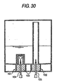
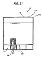
Fig. 30 shows an example of such an ink cartridge. In the ink cartridge,plug members 103 made of synthetic rubber are attached to anink supplying portion 101 and an atmosphericair introducing portion 102, respectively. When the ink cartridge 100 is attached to an inkjet printer, anink supply pipe 104 and an atmosphericair introduction pipe 105 which are disposed on the inkjet printer, which are made of a metal, and which have a needle-like hollow shape, pierce through the twoplug members 103, respectively. In anink cartridge 110 shown inFig. 31 , anink supplying portion 111 is configured in the same manner as that of the ink cartridge ofFig. 30 , but an atmosphericair introducing portion 112 is configured so that an atmosphericair introducing port 115 formed in an upper end portion of theink cartridge 110 is closed by aseal tape 116 or the like. When theink cartridge 110 is attached to an inkjet printer, the operator peels off theseal tape 116 to expose the atmosphericair introducing port 115 to the outside. In another ink cartridge, valve mechanisms which can prevent ink leakage from occurring are disposed in an ink supplying portion and an atmospheric air introducing portion, respectively (for example, see JP-A-2001-328279 (Fig. 1 )). - In the ink cartridges shown in
Figs. 30 and31 , the ink supply pipe and the atmospheric air introduction pipe which have a needle-like hollow shape, and which pierce through the synthetic rubber-made plug members in the attached state, are made of a metal. Particularly, the ink cartridge ofFig. 30 requires the two metal needles. This is disadvantageous from the viewpoint of the production cost of an inkjet printer. In the ink cartridge ofFig. 31 , the atmospheric air introducing port is exposed to the outside in a state where the ink cartridge is detached from the inkjet printer in order to be replaced with a fresh one. In the case where, for example, the detached ink cartridge is placed on a desk, the ink remaining in the cartridge may leak from the atmospheric air introducing port to the outside depending on the placement direction of the cartridge. In the ink supplying portion, the plug member is once pierced by the ink supply pipe, and hence there is the possibility that a small amount of ink leaks from the plug member from which the ink supply pipe has been extracted. - In the ink cartridge disclosed in JP-A-2001-328279, since the valve mechanisms are disposed respectively in the ink supplying portion and the atmospheric air introducing portion, the number of parts is increased, and the structure is complicated, whereby the production cost of the ink cartridge is increased. Also, in the ink cartridge of
Fig. 31 , the user must peel off the seal tape to open the atmospheric air introducing port. When this operation is not conducted, the ink cannot be:correctly supplied. In the ink cartridge of JP-A-2001-328279, the atmospheric air introducing port is closed by a check valve, and hence the atmospheric air introducing port does not fail to be opened. However, in the case where, when the atmospheric air introducing port is opened, the pressure difference between the exterior and interior of the ink cartridge is equal to or larger than a predetermined value, the pressure of the ink in the cartridge pulsates, and hence the pressure of the ink supplied to the inkjet head becomes unstable. - It is an object of the invention to surely prevent ink leakage fromoccurring in a state where an ink cartridge is detached from an inkjet printer, simplify a structure for preventing such ink leakage from occurring, and reduce the production cost. It is another object of the invention to surely open an ink supplying path and an atmospheric air introducing path in conjunction with an operation of attaching an ink cartridge.
- According to an aspect of the invention, there is provided an ink cartridge according to claim 1.
- When the ink cartridge is attached to an inkjet printer, the ink supply pipe disposed on the inkjet printer is attached to the cartridge body. In the valve mechanism, the first opening-closing portion opens the ink path in conjunction of the operation of attaching the ink supply pipe, and the second opening-closing portion opens the atmospheric air path.
- In conjunction with the operation of attaching the ink supply pipe, therefore, both the ink path and the atmospheric air path can be opened by the single valve mechanism. As a result, the number of parts can be reduced, and the structure can be simplified, so that the production cost can be lowered. Unlike the case of the conventional ink cartridge, the ink supply pipe is not required to pierce through a plug member for sealing. Therefore, the ink supply pipe is not always necessary to be made of a metal, and can be configured by an economical material which is relatively soft, such as a synthetic resin.
- According to another aspect of the invention, there is provided an inkjet printer according to claim 13. When, in conjunction with an operation of attaching the ink supply pipe, the second opening-closing portion is moved by the operating portion which butts against the second opening-closing portion, therefore, the atmospheric air path can be easily opened.
- The present invention may be more readily described with reference to the accompanying drawings:
-
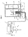
Fig. 1 is a diagram of an ink cartridge and an inkjet printer in a first embodiment of the invention; -
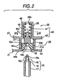
Fig. 2 is an enlarged view of a valve mechanism before the ink cartridge is attached; -
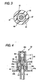
Fig. 3 is a sectional view taken along the line III-III inFig. 2 ; -
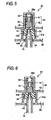
Fig. 4 is an enlarged view of the valve mechanism during an operation of attaching the ink cartridge; -
Fig. 5 is an enlarged view of the valve mechanism in a state where the operation of attaching the ink cartridge is completed; -
Fig. 6 is an enlarged view of the valve mechanism during an operation of detaching the ink cartridge; -
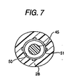
Fig. 7 is a view of a modification of the first embodiment and corresponding toFig. 3 ; -
Fig. 8 is an enlarged view of a valve mechanism before an ink cartridge of Modification A is attached; -
Fig. 9 is an enlarged view of the valve mechanism during an operation of attaching the ink cartridge; -
Fig. 10 is an enlarged view of the valve mechanism in a state where the operation of attaching the ink cartridge is completed; -
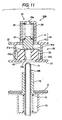
Fig. 11 is an enlarged view of a valve mechanism before an ink cartridge of Modification B is attached; -
Fig. 12 is an enlarged view of the valve mechanism during an operation of attaching the ink cartridge; -
Fig. 13 is an enlarged view of the valve mechanism in a state where the operation of attaching the ink cartridge is completed; -
Fig. 14 is an enlarged view of a valve mechanism before an ink cartridge of Modification C is attached; -
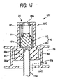
Fig. 15 is an enlarged view of the valve mechanism during an operation of attaching the ink cartridge; -
Fig. 16 is an enlarged view of the valve mechanism in a state where the operation of attaching the ink cartridge is completed; -
Fig. 17 is an enlarged view of a valve mechanism during an operation of attaching an ink cartridge Modification D; -
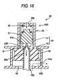
Fig. 18 is an enlarged view of the valve mechanism in a state where the operation of attaching the ink cartridge is completed; -
Fig. 19 is a longitudinal-sectional view of an ink cartridge of a second embodiment; -
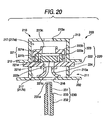
Fig. 20 is an enlarged view of a valve mechanism before the ink cartridge is attached; -
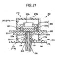
Fig. 21 is an enlarged view of the valve mechanism during an operation of attaching the ink cartridge; -
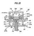
Fig. 22 is an enlarged view of the valve mechanism in a state where the operation of attaching the ink cartridge is completed; -
Fig. 23 is a longitudinal sectional view of an ink cartridge of a third embodiment; -
Fig. 24 is an enlarged view of a valve mechanism during an operation of attaching the ink cartridge; -
Fig. 25 is a sectional view taken along the line A-A inFig. 24 ; -
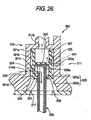
Fig. 26 is an enlarged view of the valve mechanism in a state where the operation of attaching the ink cartridge is completed; -
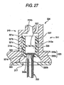
Fig. 27 is an enlarged view of the valve mechanism during an operation of detaching the ink cartridge; -
Fig. 28 is a longitudinal sectional view of an ink cartridge of a modification of the third embodiment; -
Fig. 29 is an enlarged view of a place where a valve member and an ink supply pipe are engaged with each other; -
Fig. 30 is a sectional view of a conventional ink cartridge; and -
Fig. 31 is a sectional view of another conventional ink cartridge. - A first embodiment of the invention will be described. In the first embodiment, the invention is applied to an ink cartridge which is to be attached to an inkjet printer.
- First, an inkjet printer 1 will be briefly described.
- As shown in
Fig. 1 , the inkjet printer 1 has: aninkjet head 2 havingnozzles 2a from which an ink I is ejected toward a recording sheet P; acarriage 5 which linearly moves theinkjet head 2 in one direction in a reciprocal manner; a transportingmechanism 6 which transports the recording sheet P; a purging device 7 which sucks air bubbles and the thickened ink I in theinkjet head 2; and an attachingportion 4 to which an ink cartridge 3 is to be detachably attached. Anink supply pipe 15 is fixed to the attachingportion 4 in a state where the ink supply pipe protrudes upward. - The ink I in the ink cartridge 3 is supplied to the
nozzles 2a of theinkjet head 2 via anink supply pipe 15. While theinkjet head 2 is reciprocally moved by thecarriage 5 in the direction perpendicular to the plane inFig. 1 , the ink I is ejected from thenozzles 2a toward the recording sheet P which is transported by the transportingmechanism 6 in a lateral direction inFig. 1 , thereby conducting a printing process on the recording sheet P. - The purging device 7 has: a
purge cap 10 which is movable in approaching/separating directions to an ink ejection surface, and which can cover the ink ejection surface of theinkjet head 2; and asuction pump 11 which sucks the ink I from thenozzles 2a. When theinkjet head 2 is outside the printable range where the printing process can be conducted on the recording sheet P, air bubbles entering theinkjet head 2, and the ink I which is thickened as a result of evaporation of water can be sucked from thenozzles 2a by thesuction pump 11. - Next, the ink cartridge 3 will be described.
- As shown in
Fig. 1 , the ink cartridge 3 has: acartridge body 20 having anink storing space 25 which stores the ink I; acover member 21 which covers the lower end of thecartridge body 20; and avalve mechanism 22 that can open and close both an ink path 23 (seeFigs. 4 and5 ) through which the ink is supplied to theinkjet head 2, and an atmospheric air path 24 (seeFig. 5 ) throughwhich atmospheric air is introduced into theink storing space 25. - As shown in
Fig. 2 , theink supply pipe 15 is formed into a hollow needle-like shape by a synthetic resin, and the inner path of theink supply pipe 15 is connected via a supply tube 8 to theinkjet head 2. Theink supply pipe 15 has a small-diameter portion 16 which is on the side of the tip end, and a large-diameter portion 17. A taperedportion 18 through which the small-diameter portion 16 is continuously connected to the large-diameter portion 17 is disposed integrally on an outer peripheral portion of theink supply pipe 15. In the small-diameter portion 16, a plurality ofink inflow ports 16a which allow the inner path of theink supply pipe 15 to communicate with the outside are formed. - As shown in
Fig. 1 , thecartridge body 20 is formed by, for example, a synthetic resin, and apartition wall 27 is formed in thecartridge body 20 to vertically separate theink storing space 25 which is substantially hermetically sealed to store the ink I, from an atmosphericair introducing space 26 into which atmospheric air is introduced from the outside. Twotubes ink storing space 25, and which have different lengths are formed integrally with thepartition wall 27. A small-diameter hole 41 (seeFig. 2 ) which houses avalve element 45 that will be described later is formed in theshorter tube 28, and anink introducing hole 28a through which the ink I in theink storing space 25 is introduced into the small-diameter hole 41 is formed in an upper wall portion of thetube 28. Atubular member 30 which covers a large part of thetube 28, and which is downward opened is put from the upper side on thetube 28. Thetubular member 30 guides the ink I remaining in the vicinity of the bottom of theink storing space 25 to theink introducing hole 28a of thetube 28, in order to use up the ink I in theink storing space 25. By contrast, thelonger tube 29 elongates to the vicinity of a top plate of thecartridge body 20, and guides the atmospheric air in the atmosphericair introducing space 26 to an upper portion of theink storing space 25. - Also a
tube 31 which elongates toward the atmosphericair introducing space 26 is formed on thepartition wall 27. In thetube 31, the internal space is formed so as to have a diameter that is larger than that of the above-mentionedtube 28 which elongates toward theink storing space 25. A large-diameter hole 42 (seeFig. 2 ) which houses atubular member 44 that will be described later is formed in thetube 31. An atmosphericair communicating hole 31a through which the large-diameter hole 42 communicates with the atmosphericair introducing space 26 is formed in a side portion of thetube 31. - The
cover member 21 is formed by, for example, a synthetic resin, and fixed to a lower end portion of thecartridge body 20 by welding or the like. The atmosphericair introducing space 26 is formed by thecover member 21 and thepartition wall 27. Aninsertion hole 43 which communicates with avalve housing hole 40 that will be described later, and into which theink supply pipe 15 is to be inserted from the outside is formed in thecover member 21. - As shown in
Fig. 2 , thevalve mechanism 22 has: thevalve housing hole 40 which is formed in thecartridge body 20, and which constitutes parts of theink path 23 and theatmospheric air path 24; a tubular member 44 (second opening-closing portion) which is attached into thevalve housing hole 40 so as to be slidable in the vertical directions (the insertion and counter-insertion directions of the ink supply pipe 15), and which has a throughhole 44a, theink supply pipe 15 being to be passed through the through hole; the valve element 45 (first opening-closing portion) which is disposed in thevalve housing hole 40 so as to be movable in the vertical directions to be buttable and approachable/separable with respect to thetubular member 44, the valve element closing the throughhole 44a in a state where the valve element butts against thetubular member 44; and a coil spring 46 (urging member) which urges thevalve element 45 in a downward direction (in the direction along which theink path 23 and theatmospheric air path 24 are closed). Thetubular member 44 and thevalve element 45 are juxtaposed in the insertion direction of theink supply pipe 15. Thetubular member 44 and thevalve element 45 function as a valve member. - The
valve housing hole 40 includes the small-diameter hole 41 formed in thetube 28, and the large-diameter hole 42 which communicates with the lower end of the small-diameter hole 41, and which is formed in thetube 31. Theinsertion hole 43 formed in thecover member 21 communicates with the lower end of the large-diameter hole 42. The lower end of thevalve housing hole 40 is opened to the outside through theinsertion hole 43 so that theink supply pipe 15 can be inserted into thevalve housing hole 40 from the lower side. The diameter of theinsertion hole 43 is smaller than that of the large-diameter hole 42, and thetubular member 44 attached to the large-diameter hole 42 is engaged with thecover member 21 so as not to escape from the large-diameter hole 42. Theink introducing hole 28a and the atmosphericair communicating hole 31a which have been described above are disposed on the side of theink storing space 25 with respect to the lower end of thevalve housing hole 40. Thevalve element 45 and thetubular member 44 are placed in the small-diameter hole 41 and the large-diameter hole 42 so as to correspond to theink introducing hole 28a and the atmosphericair communicating hole 31a, respectively. - The
tubular member 44 is an elastic member made of, for example, synthetic rubber, and configured so as to, in the large-diameter hole 42, be movable in the axial direction between an atmospheric air closing position (seeFigs. 2 and4 ) where the side face of thetubular member 44 is opposed to the atmosphericair communicating hole 31a to close the hole, and a position where the side face is not opposed to the atmosphericair communicating hole 31a, or an atmospheric air opening position (seeFigs. 5 and 6 ) where the atmosphericair communicating hole 31a is opened. Twosealingportions 44c which annularly protrude in an outer radial direction to be in sliding contact with the inner wall of the large-diameter hole 42 are disposed integrally on outer peripheral portions of upper and lower end portions of thetubular member 44, respectively. Because of the sealingportions 44c, thetubular member 44 and the large-diameter hole 42 are closely contacted with each other without forming a gap, and atmospheric air is prevented from entering the atmosphericair introducing space 26 through the atmosphericair communicating hole 31a in a state where thetubular member 44 is in the atmospheric air closing position. The throughhole 44a is formed in a middle portion of the upper half of thetubular member 44. A taperedpressing face 44b (second pressing face) which is continuous to the lower end of the throughhole 44a is formed on the inner side of the lower half of thetubular member 44. - When the
ink supply pipe 15 is inserted into thecartridge body 20, as shown inFigs. 4 and5 , the small-diameter portion 16 of theink supply pipe 15 is passed through the throughhole 44a, and the taperedportion 18 is then in close contact with thepressing face 44b. Thepressing face 44b of thetubular member 44 is pressed upward (in the direction along which theatmospheric air path 24 is opened) by theink supply pipe 15, whereby thetubular member 44 is moved from the atmospheric air closing position to the atmospheric air opening position in a state where the tubular member is in close contact with the outer periphery of the large-diameter portion 17. The taperedportion 18 of theink supply pipe 15 functions as an operating portion. - The
valve element 45 is formed by, for example, a synthetic resin, and attached to the small-diameter hole 41 so as to be vertically movable. As shown inFig. 3 , plural (for example, four) guidingportions 47 which vertical elongate, and which inward protrude are formed in plural (for example, four) places arranged in the circumferential direction. Thevalve element 45 is configured so that, in the small-diameter portion 16, the valve element is guided by theplural guiding portions 47 so as to be surely vertically moved.Gaps 48 between the guidingportions 47 constitute a part of theink path 23 which communicates with the interior of thecartridge body 20. Apressing face 45a (first pressing face) against which the small-diameter portion 16 of theink supply pipe 15 that has been passed through the throughhole 44a of thetubular member 44 is to butt and upward pressed by the small-diameter portion 16 is formed on the lower end face of thevalve element 45. Also anannular sealing portion 45b which downward protrudes so as to surround thepressing face 45a is formed on the lower end face of thevalve element 45. In the sealingportion 45b, the lower end face of thevalve element 45 can butt against the upper end face of thetubular member 44. In a state where thevalve element 45 butts against thetubular member 44, the throughhole 44a is closed. In this state, the ink I is prevented from leaking from the throughhole 44a, by the sealingportion 45b. A steppedspring receiving portion 45c which receives thecoil spring 46 is formed in an upper end side portion of thevalve element 45. - The
coil spring 46 is placed between thespring receiving portion 45c of thevalve element 45 and the upper end face of thetube 28, and downward urges thevalve element 45. - Next, the opening and closing operations of the
valve mechanism 22 which are conducted during the processes of attaching and detaching the ink cartridge 3 will be described. - As shown in
Fig. 2 , in a state where the ink cartridge 3 has not yet been attached to the inkjet printer 1, first, thevalve element 45 is downward urged by the urging force of thecoil spring 46 to butt against thetubular member 44, so that the throughhole 44a of thetubular member 44 is closed by thevalve element 45. Moreover, also thetubular member 44 is downward urged via thevalve element 45 by the urging force of thecoil spring 46, and engagingly held by thecover member 21, so that thetubular member 44 is in the atmospheric air closing position where the atmosphericair communicating hole 31a is closed. - When the ink cartridge 3 is attached to the inkjet printer 1, the
ink supply pipe 15 is inserted into thecartridge body 20 through theinsertion hole 43. The ink cartridge 3 which is to be attached is relatively moved with respect to theink supply pipe 15, whereby theink supply pipe 15 is inserted into thecartridge body 20. The distance between the upper end of the taperedportion 18 of theink supply pipe 15 and the upper end of the small-diameter portion 16 is set to be longer than that between thepressing face 44b of thetubular member 44 and the upper face of thetubular member 44. As shown inFig. 4 , therefore, the small-diameter portion 16 on the tip end side of theink supply pipe 15 is first passed through the throughhole 44a of thetubular member 44, the tip end of theink supply pipe 15 butts against thepressing face 45a of thevalve element 45, thevalve element 45 is pushed up by theink supply pipe 15 against the urging force of thecoil spring 46 to be upward moved, and thevalve element 45 is separated from thetubular member 44. As indicated by the arrows inFig. 4 , therefore, theink path 23 which elongates from theink introducing hole 28a to the portion below thepressing face 45a via the small-diameter hole 41, thegaps 48, and the large-diameter hole 42 is opened. At this time, theink inflow ports 16a formed in the small-diameter portion 16 of theink supply pipe 15 which upward protrudes from the throughhole 44a communicate with the interior of the large-diameter hole 42. Since theink path 23 communicates with theink supply pipe 15 in a state where thepressing face 44b of thetubular member 44 is in close contact with the taperedportion 18 of theink supply pipe 15, the ink is prevented from downward flowing out along the outer peripheral face of theink supply pipe 15 when the ink is supplied to theink supply pipe 15. - When the
ink supply pipe 15 is further inserted, as shown inFig. 5 , the taperedportion 18 of theink supply pipe 15 presses thepressing face 44b of thetubular member 44 to upward move integrally thetubular member 44 and thevalve element 45 against the urging force of thecoil spring 46. At this time, thetubular member 44 is moved from the atmospheric air closing position ofFig. 4 to the atmospheric air opening position ofFig. 5 , and hence the atmosphericair communicating hole 31a communicates with the large-diameter hole 42. As indicated by the broken arrow inFig. 5 , therefore, theatmospheric air path 24 which elongates from theinsertion hole 43 to the atmosphericair communicating hole 31a and the atmosphericair introducing space 26 is opened, and atmospheric air is introduced via thetube 29 into the ink storing space 25 (seeFig. 1 ). As a result, as indicated by the solid lines inFig. 5 , the ink in theink storing space 25 is supplied to theinkjet head 2 via theink path 23 and theink supply pipe 15. In the ink cartridge 3 of the first embodiment, when theink supply pipe 15 is inserted, thevalve element 45 is upward moved in conjunction with the inserting operation to Open theink path 23, and also thetubular member 44 is then upward moved to open theatmospheric air path 24. - By contrast, when the ink cartridge 3 is detached from the inkjet printer 1, the
ink supply pipe 15 is extracted from thecartridge body 20. As shown inFig. 6 , first, thevalve element 45 is downward urged by the urging force of thecoil spring 46 to butt against thetubular member 44, and theink path 23 is closed. Thevalve element 45 and thetubular member 44 are integrally downward moved by the urging force of thecoil spring 46, thetubular member 44 is moved from the atmospheric air opening position ofFig. 5 to the atmospheric air closing position ofFig. 2 where the tubular member is engaging held by thecover member 21, and theatmospheric air path 24 is closed. In the cage where the ink cartridge 3 is detached, when thevalve member 45 and thetubular member 44 are downward moved during a period from the timing when theink path 23 is closed to that when theatmospheric air path 24 is closed, the ink I inflows from theink storing space 25 into thevalve housing hole 40 via theink introducing hole 28a, and hence the pressure in theink storing space 25 is slightly lowered. Immediately before theatmospheric air path 24 is closed, the external atmospheric air is sucked into the atmosphericair introducing space 26 via theinsertion hole 43 and the atmosphericair communicating hole 31a. Therefore, a small amount of the ink I which outflows into the large-diameter hole 42 together with the extractedink supply pipe 15 is sucked together with the atmospheric air into the atmosphericair introducing space 26. Consequently, the ink I can be prevented from adhering to the vicinity of theinsertion hole 43, so that contamination of the hands of the operator, and leakage of the ink I in the case where the detached ink cartridge 3 is placed on a desk or the like can be prevented from occurring. - In the above-described ink cartridge 3, in conjunction with the operations of inserting and extracting the
ink supply pipe 15, both theink path 23 and theatmospheric air path 24 can be opened and closed by thesingle valve mechanism 22. Therefore, the number of parts can be reduced, and the structure can be simplified, so that the production cost can be lowered. - The
ink supply pipe 15 is requested only to have a strength which enables the ink supply pipe to push up thevalve element 45 and thetubular member 44 against the urging force of thecoil spring 46. Therefore, the ink supply pipe is not requested to have a strength which enables the ink supply pipe to pierce through aplug member 103 of the conventional ink cartridge (seeFigs. 30 and31 ). Consequently, theink supply pipe 15 can be configured by a material which is relatively soft, such as a synthetic resin. This is advantageous from the viewpoint of the cost of parts. - In the ink cartridge 3, the first and second opening-closing
portions portions portions - In the ink cartridge 3, the valve mechanism has a
valve housing hole 40 which is formed in thecartridge body 20, and which constitutes parts of the ink path and the atmospheric air path, one end of thevalve housing hole 40 is opened to an outside to enable theink supply pipe 15 to be inserted, the valve member is housed in thevalve housing hole 40 to be movable in an insertion direction of theink supply pipe 15, an ink introduction hole and an atmospheric air communicating hole which allow an interior of the valve housing hole and the ink storing space to communicate with each other are disposed on a side of the ink storing space with respect to the one end of thevalve housing hole 40, and the first and second opening-closingportions - In the ink cartridge 3, when the
ink supply pipe 15 is inserted into thevalve housing hole 40 from the opened one end of the valve housing hole, the valve member is moved in the insertion direction of the ink supply pipe in accordance with the operation of inserting the ink supply pipe, and the ink introduction hole and the atmospheric air communicating hole are opened by the first and second opening-closing portions, respectively. Therefore, atmospheric air is introduced into the ink storing space through the atmospheric air communicating hole, and the ink is supplied from the ink storing space into the ink supply pipe through the ink introduction hole. - In the ink cartridge 3, the valve member has an internal space into which the ink supply pipe is to be inserted, and, when the
ink supply pipe 15 is inserted into the internal space, the valve member is in close contact with an outer periphery of the ink supply pipe and causes the ink path to communicate with the ink supply pipe. As described above, the ink path communicates with the ink supply pipe in a state where the valve member is in close contact with the outer periphery of the ink supply pipe. When the ink is supplied from the ink path into the ink supply pipe, therefore, the ink can be prevented from flowing to the outside. - In the ink cartridge 3, the first and second opening-closing
portions member 46 for urging the first and second opening-closingportions ink supply pipe 15 is not inserted into thevalve housing hole 40, the first opening-closingportion 45 is urged by the urgingmember 46 to butt against the second opening-closingportion 44, thereby closing the ink path, and the second opening-closingportion 44 is urged by the urgingmember 46 to close the atmospheric air path, and, in conjunction with the operation of inserting theink supply pipe 15 into thevalve housing hole 40, the second opening-closingportion 44 is moved to open the atmospheric air path, and the first opening-closingportion 45 is separated from the second opening-closingportion 44 to cause the ink path to communicate with the ink supply pipe. - In the ink cartridge 3, the first and second opening-closing
portions valve housing hole 40, the first opening-closing portion is urged by the urgingmember 46 to butt against the second opening-closing portion, and the ink path is closed by the first opening-closing portion. Moreover, also the second opening-closing portion is urged by the urgingmember 46, and the atmospheric air path is closed by the second opening-closing portion. When theink supply pipe 15 is inserted into thevalve housing hole 40, the second opening-closing portion is moved in the valve housing hole to open the atmospheric air path in conjunction with the operation of inserting the ink supply pipe, and the first opening-closing portion is separated from the second opening-closing portion, so that the ink path and the ink supply pipe communicate with each other. Therefore, the ink in the ink storing space is supplied into theink supply pipe 15 through the ink path. - In the ink cartridge 3, the second opening-closing
portion 44 has a through hole into which theink supply pipe 15 is to be inserted, in a state where the ink supply pipe is not inserted into the through hole, the first opening-closingportion 45 is urged by the urging member to butt against the second opening-closing portion, thereby closing the through hole, and, in conjunction with an operation of inserting the ink supply pipe into the through hole, the first opening-closing portion is separated from the second opening-closing portion to cause the ink path to communicate with the ink supply pipe. When the ink supply pipe is inserted into the through hole of the second opening-closing portion, therefore, the first opening-closing portion is separated from the second opening-closing portion in conjunction with the inserting operation, whereby the through hole is opened and the ink path communicates with the ink supply pipe. - In the ink cartridge 3, when the
ink supply pipe 15 is extracted from the through hole, the first opening-closingportion 45 is caused by the urging member to butt against the second opening-closingportion 44, thereby closing the through hole, and the first and second opening-closing portions are then integrally moved to close the atmospheric air path. When the ink supply pipe is extracted, therefore, the first and second opening-closing portions are moved integrally with each other during a period from a timing when the first opening-closing portion butts against the second opening-closing portion to close the ink path to that when the atmospheric air path is closed. Consequently, the ink of an amount corresponding to the movement of the first and second opening-closing portions flows from the cartridge body into the valve housing hole. As a result, the pressure in the cartridge body is slightly lowered, and the ink which adheres to the interiors of the ink supply pipe and the valve housing hole is sucked into the atmospheric air path immediatelybefore the atmospheric air path is closed. Therefore, the ink hardly outflows to the exterior of the valve housing hole. - In the ink cartridge 3, the first opening-closing
portion 45 has a first pressing face which is to be pressed by a tip end portion of theink supply pipe 15 in a direction along which the ink path is opened, and the second opening-closingportion 44 has a second pressing face which, in conjunction with the operation of attaching the ink supply pipe, is to be pressed in a direction along which the atmospheric air path is opened. When theink supply pipe 15 is attached to the cartridge body, therefore, the first pressing face of the first opening-closing portion is pressed by the tip end portion of the ink supply pipe, and the first opening-closing portion opens the ink path. In conjunction with the operation of attaching the ink supply pipe, then, the second pressing face of the second opening-closing portion is pressed, and the second opening-closing portion opens the atmospheric air path. - In the inkjet printer 1, the operating portion is formed integrally with an outer peripheral portion of the
ink supply pipe 15. Therefore, it is not required to produce the operating portion as a component which is different from the ink supply pipe, so that the operating portion can be easily formed integrally with the ink supply pipe. - Next, modifications in which the first embodiment is variously modified will be described. The components which are configured in the same manner as those of the embodiment are denoted by the same reference numerals, and their description is often omitted.
- As the urging member which downward urges the
valve element 45 and thetubular member 44, another spring member such as a disc spring may be used in place of thecoil spring 46 in the embodiment. Alternatively, the urging member may be made of elastic synthetic rubber or the like. - The guiding portion which guides the
valve element 45 to move in the small-diameter hole 41 is not limited to the guiding portions 47 (seeFig. 3 ) of the first embodiment. As shown inFig. 7 , for example, aninner face 50 of the small-diameter hole 41 may function as the guiding portion, andgrooves 51 formed in theinner face 50 may constitute a part of theink path 23. Alternatively, the guidingportions 47 or thegrooves 51 may be disposed in the outer periphery of thevalve element 45. - The operation of inserting or extracting the
ink supply pipe 15 into thecartridge body 20 via theinsertion hole 43 is not limited to insertion or extraction which is conducted by moving the ink cartridge 3 with respect to the fixedink supply pipe 15. The operation of inserting or extracting may be conducted by moving theink supply pipe 15 with respect to the fixed ink cartridge 3. - Modifications (Modifications A to D) of the first embodiment in which the configuration of the valve mechanism is modified will be described.
- As shown in
Figs. 8 to 10 , avalve mechanism 22A of anink cartridge 3A of Modification A has: avalve housing hole 40 which is formed in thecartridge body 20, and which constitutes parts of anink path 23A (seeFig. 10 ) and anatmospheric air path 24A (seeFigs. 9 and10 ); a tubular member 60 (second opening-closingportion) which is attached into thevalve housing hole 40 so as to be slidable in the vertical directions, and which has a throughhole 60a, anink supply pipe 15A being to be passed through the through hole; a valve element 61 (first opening-closing portion) which is disposed in thevalve housing hole 40 so as to be movable in the vertical directions to be approachable/separable with respect to thetubular member 60, the valve element closing the throughhole 60a in a state where the valve element butts against thetubular member 60; and a coil spring 62 (urging member) which urges thevalve element 61 in a downward direction. Thetubular member 60 and thevalve element 61 are juxtaposed in the insertion direction of theink supply pipe 15A. - The
valve housing hole 40 is similar to that in the embodiment described above, and includes the small-diameter hole 41 formed in thetube 28, and the large-diameter hole 42 which communicates with the lower end of the small-diameter hole 41, and which is formed in thetube 31. The lower end of thevalve housing hole 40 is opened to the outside through theinsertion hole 43 formed in thecover member 21, thereby enabling theink supply pipe 15A to be passed into thevalve housing hole 40 from the lower side. - The
tubular member 60 is fittingly attached into the large-diameter hole 42 so as to be vertically slidable between an atmospheric air closing position (seeFig. 8 ) where the atmosphericair communicating hole 31a formed in thetube 31 is closed, and an atmospheric air opening position (seeFigs. 9 and10 ) where the atmosphericair communicating hole 31a is opened. The throughhole 60a into which theink supply pipe 15A is to be inserted is formed in a middle portion of the upper half of thetubular member 60. A taperedface 60c which is used for enabling theink supply pipe 15A to be smoothly inserted into the throughhole 60a, and in which the diameter is larger as further downward advancing is formed in the lower end of the throughhole 60a so as to be continuous to the throughhole 60a. In a state where theink supply pipe 15A is inserted into the throughhole 60a, thetubular member 60 is in close contact with the outer periphery of theink supply pipe 15A. Acoil spring 63 is placed inside the lower half of thetubular member 60. An annularspring receiving member 64 which receives thecoil spring 63 from the lower side is disposed so as to be vertically movable relative to thetubular member 60. - Two sealing
portions 60b which annularly protrude in an outer radial direction to be in sliding contact with the inner wall of the large-diameter hole 42 are disposed integrally on outer peripheral portions of upper and lower end portions of thetubular member 60, respectively. The two sealingportions 60b are in contact with the inner wall of the large-diameter hole 42, ina statewhere the sealingportions are slightlydownward inclined, so that the resistance actingbetween thetubularmember 60 and the large-diameter hole 42 when the tubular member is downward moved is larger than that acting when the tubular member is upward moved. In a state where thetubular member 60 and the large-diameter hole 42 are closely contacted with each other without forming a gap and thetubular member 60 is in the atmospheric air closing position (seeFig. 8 ), atmospheric air is prevented by the sealingportions 60b from flowing from the outside into the atmospheric air introducing space 26 (seeFig. 1 ) through the atmosphericair communicating hole 31a. - The
valve element 61 is configured in a substantially same manner as the valve element 45 (seeFigs. 2 to 6 ) of the first embodiment. Namely, thevalve element 61 is attached to the small-diameter hole 41 so as to be vertically movable in a state where the valve element is guided by the guidingportions 47 formed on the inner side face of the small-diameter hole 41. The gaps between the guidingportions 47 constitute a part of theink path 23A. Apressing face 61a and anannular sealing portion 61b which are upward pressed by a small-diameter portion 16A of theink supply pipe 15A are formed on the lower end face of thevalve element 61. - In the small-
diameter hole 41, thecoil spring 62 is placed above thevalve element 61, so that thevalve element 61 is downward urged by thecoil spring 62. The elastic force of thecoil spring 62 is weaker than that of thecoil spring 63 placed in thetubular member 60. - As shown in
Figs. 8 to 10 , theink supply pipe 15A which protrudes from the attachingportion 4 of the inkjet printer has the small-diameter portion 16A which is on the side of the tip end, and a large-diameter portion 17A. An operatingportion 65 through which the small-diameter portion 16A is continuously connected to the large-diameter portion 17A is formed integrally on an outer peripheral portion of theink supply pipe 15A. A tip end portion of the small-diameter portion 16A is formed into a rounded shape. In the small-diameter portion 16A, a plurality ofink inflow ports 66 which allow the interior of theink supply pipe 15A to communicate with the exterior are formed. The operatingportion 65 is formed as an annular face which, when theink supply pipe 15A is inserted into the throughhole 60a, can butt against the annularspring receiving member 64. - Next, the opening and closing operations of the
valve mechanism 22A which are conducted during the processes of attaching and detaching theink cartridge 3A will be described. - As shown in
Fig. 8 , in a state where theink supply pipe 15A has not yet been inserted into thecartridge body 20, thevalve element 61 is downward urged by the urging force of thecoil spring 62 to butt against thetubular member 60, so that the throughhole 60a of thetubular member 60 is closed by thevalve element 61. Moreover, also thetubular member 60 is downward urged via thevalve element 61 by the urging force of thecoil spring 62, and engagingly held by thecover member 21, so that thetubular member 60 is in the atmospheric air closing position where the atmosphericair communicating hole 31a is closed. - When the
ink cartridge 3A is attached to the inkjet printer, theink supply pipe 15A is inserted into thecartridge body 20 through theinsertion hole 43. As shown inFig. 9 , then, the small-diameter portion 16A of theink supply pipe 15A is inserted into the throughhole 60a, and the operatingportion 65 having the annular face butts against the lower face of the annularspring receiving member 64. The distance between the operatingportion 65 of theink supply pipe 15A and the upper end of the small-diameter portion 16A is set to be shorter than that between the lower face of thespring receiving member 64 and thetubular member 60. Therefore, the upper end of theink supply pipe 15A has not yet butted against thevalve element 61. The resistance acting between the sealingportions 60b and the large-diameter hole 42 when thetubular member 60 is upward moved is smaller than that acting when the tubular member is downward moved, so that thetubular member 60 can be upward moved in a relatively smooth manner. Moreover, the elastic force of thecoil spring 63 which is received by thespring receiving member 64 is stronger than that of thecoil spring 62 which downward urges thevalve element 61. When the insertion of theink supply pipe 15A is further advanced, therefore, the operatingportion 65 pushes up thetubular member 60 via thespring receiving member 64 and thecoil spring 63, and, in conjunction with the operation of inserting theink supply pipe 15A, thetubular member 60 and thevalve element 61 are integrally upward pushed up against the urging force of thecoil spring 62 until the upper face of thetubular member 60 butts against the upper wall of the large-diameter hole 42, i.e., thepartition wall 27. As a result, thetubular member 60 is moved from the atmospheric air closing position ofFig. 8 to the atmospheric air opening position ofFig. 9 , and hence the atmosphericair communicating hole 31a communicates with the large-diameter hole 42. As indicated by the broken arrow inFig. 9 , therefore, the atmospheric air path 24Awhich elongates from theinsertion hole 43 to the atmosphericair communicating hole 31a and the atmosphericair introducing space 26 is opened, and atmospheric air is introduced into theink storing space 25. - When the
ink supply pipe 15A is further inserted into thevalve housing hole 40 in a state where, as shown inFig. 9 , thetubular member 60 butts against the upper wall of the large-diameter hole 42 and is in the atmospheric air opening position, theink supply pipe 15A is upward moved while the operating portion of theink supply pipe 15A compresses thecoil spring 63 as shown inFig. 10 , the tip end of the small-diameter portion 16A butts against thepressing face 61a of thevalve element 61 to push up thevalve element 61, and thevalve element 61 is separated from thetubular member 60. As indicated by the arrows inFig. 10 , therefore, theink path 23A which elongates from theink introducing hole 28a to the portion below thepressing face 61a via the small-diameter hole 41, and the gaps between the valve element and the small-diameter hole 41 is opened. At this time, theink inflow ports 66 of the small-diameter portion 16A which upward protrudes from the throughhole 60a communicate with the interior of the large-diameter hole 42. Since theink path 23A communicates with theink supply pipe 15A in a state where the throughhole 60a is in close contact with the outer periphery of theink supply pipe 15A, the ink is prevented from downward flowing out along the outer face of theink supply pipe 15A when the ink is supplied to theink supply pipe 15A. - After being produced, the
ink cartridge 3A is vacuum packed in a sealed bag, and also the interior of thecartridge body 20 is depressurized. In the case where theink cartridge 3A is attached to the inkjet printer, when theink path 23A is opened by thevalve element 61 before theatmospheric air path 24A is opened by thetubular member 60, therefore, the ink in theink supply pipe 15A reversely flows into thecartridge body 20 in a decompressed state. Then, atmospheric air penetrates through nozzles of theinkjet head 2 connected to theink supply pipe 15A, thereby causing the possibility that the ink cannot be correctly ejected from theinkjet head 2. In Modification A, by contrast, when theink supply pipe 15A is inserted into thecartridge body 20, thetubular member 60 is upward moved in conjunction with the inserting operation to open theatmospheric air path 24A, and also thevalve element 61 is then upward moved to open theink path 23A. Therefore, the ink does not reversely flow from theink supply pipe 15A into theink cartridge 3A. - By contrast, in the case where the
ink cartridge 3A is detached from the inkjet printer, when theink supply pipe 15A is extracted from thecartridge body 20, thevalve element 61 is downward urged by the urging force of thecoil spring 62 to butt against thetubular member 60, and theink path 23A is closed. Thevalve element 61 and thetubular member 60 are integrally downward moved by the urging force of thecoil spring 62, and theatmospheric air path 24A is closed. - In the
ink cartridge 3A, when theink supply pipe 15A is attached to the cartridge body, the second opening-closingportion 60 opens the atmospheric air path, and the first opening-closingportion 61 then opens the ink path. After production, an ink cartridge is vacuum packed in a sealed bag, and also the interior of the cartridge body is depressurized. In the case where the ink cartridge is attached to the inkjet printer, when the ink path is opened by the first opening-closing portion before the atmospheric air path is opened by the second opening-closing portion, therefore, the ink in the ink supply pipe reversely flows into the cartridge body in a decompressed state. Then, atmospheric air penetrates through nozzles of an inkjet head connected to the ink supply pipe, thereby causing the possibility that the ink cannot be correctly ejected from the inkjet head. By contrast, the ink cartridge of the eighth invention is configured so that the second opening-closing portion opens the atmospheric air path, and the first opening-closing portion then opens the ink path. Therefore, the ink does not reversely flow into the ink cartridge, and the ink can be correctly ejected from the inkjet head. - In the
ink cartridge 3A, the first and second opening-closingportions ink supply pipe 15A, the first and second opening-closing portions are integrally moved to open the atmospheric air path, and the first opening-closing portion is then separated from the second opening-closing portion to open the inkpath. When the ink supply pipe is attached to the cartridge body, therefore, the second opening-closing portion opens the atmospheric air path, and the first opening-closing portion is then separated from the second opening-closing portion to open the ink path. As a result, the ink does not reversely flow from the ink supply pipe into the ink cartridge. - Modification B is different from Modification A in the shape of the tubular member. As shown in
Figs. 11 to 13 , atubular member 70 of avalve mechanism 22B is fittingly attached into the large-diameter hole 42 so as to be vertically slidable. A throughhole 70a into which anink supply pipe 15B is to be inserted is formed in thetubular member 70. In a state where theink supply pipe 15B is inserted into the throughhole 70a, thetubular member 70 is in close contact with the outer periphery of theink supply pipe 15B. In the same manner as Modification A, two sealingportions 70b are disposed on an outer peripheral portion of thetubular member 70. - As shown in
Figs. 11 to 13 , a tip end portion of theink supply pipe 15B which is protrudingly disposed in the attachingportion 4 of the inkjet printer is formed into a rounded shape. In the tip end portion, a plurality ofink inflow ports 71 which allow the interior of theink supply pipe 15B to communicate with the exterior are formed. Atubular operating portion 72 is fitted onto theink supply pipe 15B so as to be vertically movable relative to theink supply pipe 15B. Thetubular operating portion 72 is upward urged by acoil spring 74 which is housed in aspring housing chamber 73 in a bottom portion of the attachingportion 4. The elastic force of thecoil spring 74 is stronger than that of thecoil spring 62 which downward urges thevalve element 61. In a state where the operatingportion 72 is pushed up by thecoil spring 74 before anink cartridge 3B is attached to the attachingportion 4, the distance between the upper end of the operatingportion 72 and the end of theink supply pipe 15B is set to be shorter than that between the lower and upper faces of thetubular member 70. In this state, the upper end of theink supply pipe 15B is not required to protrude from the upper end of the operatingportion 72. - Next, operations of the
valve mechanism 22B which are conducted during the processes of attaching and detaching theink cartridge 3B will be described. - As shown in
Fig. 11 , in a state where theink supply pipe 15B has not yet been inserted into thecartridge body 20, thevalve element 61 is downward urged by the urging force of thecoil spring 62 to butt against thetubular member 70, so that the throughhole 70a of thetubular member 70 is closed by thevalve element 61. Moreover, also thetubular member 70 is downward urged via thevalve element 61 by the urging force of thecoil spring 72, and engagingly held by thecover member 21, so that thetubular member 70 is in the atmospheric air closing position where the atmosphericair communicating hole 31a is closed. - As shown in
Fig. 12 , when theink supply pipe 15B is inserted into thecartridge body 20, the upper end of the operatingportion 72 butts against the lower face of thetubular member 70, but the upper end of theink supply pipe 15B has not yet butted against thevalve element 61. Since the elastic force of thecoil spring 74 which upward urges the operatingportion 72 is stronger than that of thecoil spring 62 which downward urges thevalve element 61, thetubular member 70 and thevalve element 61 are pushed up by the operatingportion 72 against the urging force of thecoil spring 62 until the upper face of thetubular member 70 butts against the upper wall of the large-diameter hole 42. As a result, thetubular member 70 is moved from the atmospheric air closing position ofFig. 11 to the atmospheric air opening position ofFig. 12 , and hence the atmosphericair communicating hole 31a communicates with the large-diameter hole 42. As indicated by the broken arrow inFig. 12 , therefore,anatmospheric air path 24B which elongates from theinsertion hole 43 to the atmosphericair communicating hole 31a and the atmosphericair introducing space 26 is opened, and atmospheric air is introduced into theink storing space 25. - When the
ink supply pipe 15B is further inserted into thevalve housing hole 40 in a state where, as shown inFig. 12 , thetubular member 70 is moved to the atmospheric air opening position and the upper face of thetubular member 70 butts against the upper wall of the large-diameter hole 42, the movements of the operatingportion 72 and thetubular member 70 are restricted, and hence only theink supply pipe 15B is further inserted into thevalve housing hole 40 against the urging forces of the coil springs 62, 74 as shown inFig. 13 . The tip end of theink supply pipe 15B butts against thepressing face 61a of thevalve element 61 to push up thevalve element 61, and thevalve element 61 is separated from thetubular member 70. As indicated by the arrow inFig. 13 , therefore, theink path 23B which elongates from theink introducing hole 28a to the portion below thepressing face 61a via the small-diameter hole 41, the gaps between thevalve element 61 and the small-diameter hole 41, and the small-diameter hole 41 is opened. At this time, theink inflow ports 71 of the tip end portion of theink supply pipe 15B which upward protrudes from the throughhole 70a communicate with the interior of the small-diameter hole 41. - The operation of the
valve mechanism 22B which is conducted during the process of detaching theink cartridge 3B is substantially identical with that in Modification A. Specif ical ly, thevalve element 61 first butts against thetubular member 70 to close theink path 23B. Then, thevalve element 61 and thetubular member 70 are integrally downward moved to close theatmospheric air path 24B. - In this inkjet printer, the
operatingportion 72 is disposed to be movable relative to theink supply pipe 15B in parallel to an attachment direction of the ink supply pipe, and, after, in conjunction with the operation of attaching the ink supply pipe, the operating portion butts against the second opening-closing portion to move the second opening-closing portion to the position where the atmospheric air path is opened, theink supply pipe 15B moves the first opening-closing portion to a position where the ink path is opened. When the ink supply pipe is attached to the cartridge body, therefore, the second opening-closing portion is moved to open the atmospheric air path, by the operating portion which is relatively movable with respect to the ink supply pipe, and the first opening-closing portion is then moved by the ink supply pipe, so that the ink path can be opened. - Modification C is different from Modifications A, B in the shape of the tubular member. A
tubular member 80 of avalve mechanism 22C is fittingly attached into the large-diameter hole 42 so as to be vertically slidable. A throughhole 80a into which anink supply pipe 15C is to be inserted is formed in thetubular member 80. Atapered hole portion 80c in which the diameter is smaller as further upward advancing is formed in an upper end portion of the throughhole 80a. When theink supply pipe 15C is inserted into the throughhole 80a, the taperedhole portion 80c is in close contact with the outer periphery of theink supply pipe 15C. The taper angle of the taperedhole portion 80c is set so that the resistance (friction force) acting between theink supply pipe 15C and the taperedhole portion 80c is larger than the elastic force of thecoil spring 62 which downward urges thevalve element 61. In the same manner as Modification A, two sealingportions 80b are disposed on an outer peripheral portion of thetubular member 80. - As shown in
Figs. 14 to 16 , a tip end portion of theink supply pipe 15C which is disposed in the attachingportion 4 of the inkjet printer is formed into a rounded shape. In the tip end portion, a plurality ofink inflow ports 81 which allow the interior of theink supply pipe 15C to communicate with the exterior are formed. - The outer peripheral portion of the
ink supply pipe 15C which pushes up thetubular member 80 by means of friction acting between the portion and the taperedhole portion 80c as described later functions also as an operating portion for thetubular member 80. - Next, operations of the
valve mechanism 22C which are conducted during the processes of attaching and detaching theink cartridge 3C will be described. As shown inFig. 14 , in a state where theink supply pipe 15C has not yet been inserted into thecartridge body 20, thevalve element 61 is downward urged by the urging force of thecoil spring 62 to butt against thetubular member 80, so that the throughhole 80a of thetubular member 80 is closed by thevalve element 61. - Also the
tubular member 80 is downward urged via thevalve element 61 by the urging force of thecoil spring 62 and engagingly held by thecover member 21, so that thetubular member 80 is in the atmospheric air closing position where the atmosphericair communicating hole 31a is closed. - As shown in
Fig. 15 , when theink supply pipe 15C is inserted into thecartridge body 20, the tip end portion of theink supply pipe 15C is inserted into the throughhole 80a of thetubular member 80, and then in contact with the taperedhole portion 80c. Since the resistance (friction force) acting between theink supply pipe 15C and the taperedhole portion 80c is larger than the elastic force of thecoil spring 62 which downward urges thevalve element 61, thetubular member 80 and thevalve element 61 are pushed up against the urging force of thecoil spring 62 until thetubular member 80 butts against the upper wall of the large-diameter hole 42. As a result, thetubular member 80 is moved from the atmospheric air closing position ofFig. 14 to the atmospheric air opening position ofFig. 15 , and hence the atmosphericair communicating hole 31a communicates with the large-diameter hole 42. As indicated by the broken arrow inFig. 15 , therefore, anatmospheric air path 24C which elongates from theinsertion hole 43 to the atmosphericair communicating hole 31a and the atmosphericair introducing space 26 is opened, and atmospheric air is introduced into theink storing space 25. At this time, a friction resistance of a certain degree is set between thetapered hole portion 80c and theink supply pipe 15C so that the tip end portion of theink supply pipe 15C may be upward exposed from the upper face of thetubular member 80 through the through 80a, but the tip end portion does not butt against thepressing face 61a of thevalve element 61. - When the
ink supply pipe 15C is further inserted into thevalve housing hole 40 in a state where, as shown inFig. 15 , thetubular member 80 is moved to the atmospheric air opening position to butt against the upper wall of the large-diameter hole 42, the tip end portion of theink supply pipe 15C is upward protruded from thetubular member 80 against the resistance acting between the tip end portion and the taperedhole portion 80c. Then, the tip end portion of theink supply pipe 15C butts against thepressing face 61a of thevalve element 61 to push up thevalve element 61, and thevalve element 61 is separated from thetubular member 80. As indicated by the arrow inFig. 16 , therefore, theink path 23C which elongates from theink introducing hole 28a to the portion below thepressing face 61a via the small-diameter hole 41, the gaps between thevalve element 61 and the small-diameter hole 41, the small-diameter hole 41 is opened. At this time, theink inflow ports 81 formed in the tip end portion of theink supply pipe 15C communicate with the interior of the small-diameter hole 41. - The operation of the
valve mechanism 22C which is conducted during the process of detaching theink cartridge 3C is substantially identical with the operations in Modifications A, B. Specifically, thevalve element 61 first butts against thetubular member 80 to close theink path 23C. Then, thevalve element 61 and thetubular member 80 are integrally downward moved to close theatmospheric air path 24C. - Modification D is different from Modifications A to C in the shape of the tubular member. As shown in
Figs. 17 and18 , atubular member 90 of avalve mechanism 22D is fittingly attached into the large-diameter hole 42 so as to be vertically slidable. A throughhole 90a into which anink supply pipe 15D is to be inserted is formed in thetubular member 90. In a state where theink supply pipe 15D is inserted into the throughhole 90a, thetubular member 90 is in close contact with the outer periphery of theink supply pipe 15D. In the same manner as Modification A, two sealing portions 90b are disposed on an outer peripheral portion of thetubular member 90. In a state where theink supply pipe 15D is not inserted into the throughhole 90a, a sealingfilm 90c which closes the throughhole 90a is formed in an upper end portion of the throughhole 90a. - As shown in
Figs. 17 and18 , a tip end portion of theink supply pipe 15D which is protrudingly disposed in the attachingportion 4 of the inkjet printer is formed into a pointed shape. In the tip end portion, a plurality ofink inflow ports 91 which allow the interior of theink supply pipe 15D to communicate with the exterior are formed. The tip end portion of theink supply pipe 15D which butts against the sealingfilm 90c in order to push up thetubular member 90 as described later, and the outer peripheral portion of the ink supplypipe 15Dwhich generates a friction force between the portion and the throughhole 90a function also as an operating portion for thetubular member 90. - Operations of the
valve mechanism 22D which are conducted during the processes of attaching and detaching theink cartridge 3D will be described. - In a state where the
ink supply pipe 15D has not yet been inserted into thecartridge body 20, thevalve element 61 is downward urged by the urging force of thecoil spring 62 to butt against thetubular member 90. The throughhole 90a of thetubular member 90 is sealed by the sealingfilm 90c to attain a state where anink path 23D is closed. Moreover, also thetubular member 90 is downward urged via thevalve element 61 by the urging force of thecoil spring 62, and engagingly held by thecover member 21, so that thetubular member 90 is in the atmospheric air closing position where the atmosphericair communicating hole 31a is closed. - As shown in
Fig. 17 , when theink supply pipe 15D is inserted into thecartridge body 20, the tip end portion of theink supply pipe 15D is inserted into the throughhole 90a of thetubular member 90. At this time, the tip end portion of theink supply pipe 15D butts against the sealingfilm 90c. The sum of the resistance (friction force) acting between thetubular member 90 and theink supply pipe 15D, and the force at which thesealing film 90c is smashed by theink supply pipe 15D is larger than the urging force of thecoil spring 62 which downward urges thevalve element 61. Therefore, thetubular member 90 and thevalve element 61 are pushed up against the urging force of thecoil spring 62 until thetubular member 90 butts against the upper wall of the large-diameter hole 42. As a result, thetubular member 90 is moved to the atmospheric air opening position ofFig. 17 , and hence the atmosphericair communicating hole 31a communicates with the large-diameter hole 42. As indicated by the broken arrow inFig. 18 , therefore, anatmospheric air path 24D which elongates from theinsertion hole 43 to the atmosphericair communicating hole 31a and the atmosphericair introducing space 26 is opened, and atmospheric air is introduced into theink storing space 25. - When the
ink supply pipe 15D is further inserted into thevalve housing hole 40 in a state where, as described above, thetubular member 90 is moved to the atmospheric air opening position, the tip end portion of theink supply pipe 15D having a pointed shape smashes the sealingfilm 90c, and is then upward protruded from thetubular member 90. Then, the tip end portion of theink supply pipe 15D butts against thepressing face 61a of thevalve element 61 to push up thevalve element 61, and thevalve element 61 is separated from thetubular member 90. As indicated by the arrows inFig. 18 , therefore, theink path 23D which elongates from theink introducing hole 28a to the portion below thepressing face 61a via the small-diameter hole 41, the gaps between thevalve element 61 and the small-diameter hole 41, and the small-diameter hole 41 is opened. At this time, theink inflow ports 91 formed in the tip end portion of theink supply pipe 15D communicate with the interior of the small-diameter hole 41. - The operation of the
valve mechanism 22D which is conducted during the process of detaching theink cartridge 3D is substantially identical with the operations in Modifications A to C. Specifically, thevalve element 61 first butts against thetubular member 90 to close theink path 23D. Then, thevalve element 61 and thetubular member 90 are integrally downward moved to close theatmospheric air path 24D. - Next, a second embodiment of the invention will be described.
- As shown in
Fig. 19 , in the same manner as the first embodiment, anink cartridge 200 of the second embodiment has: acartridge body 201 having anink storing space 210 which stores the ink I; acover member 202 which covers the lower end of thecartridge body 201; and avalve mechanism 203 that can open and close both an ink path 240 (the solid arrows inFig. 22 ) through which the ink is supplied to theinkjet head 2, and an atmospheric air path 241 (the broken arrow inFigs. 21 and22 ) through which atmospheric air is introduced into theink storing space 210. In the same manner as the embodiment described above, anink supply pipe 230 is protrudingly disposed in the attachingportion 4. - In the
cartridge body 201, apartition wall 212 is formed to vertically separate theink storing space 210 which is substantially hermetically sealed to store the ink I, from an atmosphericair introducing space 211 into which atmospheric air is introduced from the outside. Twotubes ink storing space 210, and which have different lengths are formed integrally with thepartition wall 212. Theupper half 217a of avalve housing hole 217 which will be described later is formed in theshorter tube 213, and anink introducing hole 213a through which the ink I in theink storing space 210 is introduced into thevalve housing hole 217 is formed in an upper wall portion of thetube 213. - By contrast, the
longer tube 214 elongates to the vicinity of a top plate of thecartridge body 201, and guides the atmospheric air in the atmosphericair introducing space 211 to an upper portion of theink storing space 210. - The
cover member 202 is fixed to a lower end portion of thecartridge body 201 by welding or the like. The atmosphericair introducing space 211 is defined by thecover member 202 and thepartition wall 212. In thecover member 202, atube 215 which elongates toward the atmosphericair introducing space 211 is formed at a position corresponding to thetube 213. Thetube 215 forms thelower half 217b of thevalve housing hole 217. An atmosphericair communicating hole 215a through which the valve housing hole 217 (217b) communicates with the atmosphericair introducing space 211 is formed in a side portion of thetube 215. Aninsertion hole 216 which communicates with thelower half 217b of thevalve housing hole 217 is formed in thecover member 202. - The
valve mechanism 203 has: the valve housing hole 217 (217a, 217b) which constitutes parts of theink path 240 and theatmospheric air path 241; anelastic valve member 220 which is made of synthetic rubber or the like; and a valve element 221 (first opening-closing portion) which is made of a synthetic resin or the like, and which is housed in thevalve member 220. Thevalve member 220 has: avalve seat portion 222 having a throughhole 222a into which theink supply pipe 230 is to be inserted; an urging portion 223 (urging member) which is placed above thevalve seat portion 222; and an atmospheric air path opening-closing portion 224 (second opening-closing portion) which is placed below thevalve seat portion 222. Thevalve seat portion 222, the urgingportion 223, and the atmospheric air path opening-closing portion 224 (second opening-closing portion) are integrally configured. - An outer peripheral portion of the
valve member 220 is clamped between thepartition wall 212 and thetube 215, whereby the valve member is fixed. - The
valve seat portion 222 is formed into a substantially horizontal plate-like shape. The throughhole 222a into which theink supply pipe 230 is to be inserted is formed in a middle portion of thevalve seat portion 222. The urgingportion 223 has: a cylindricalside wall portion 223a which rises from an outer peripheral side portion of thevalve seat portion 222; and a projectedportion 223b which is radially inward projected integrally from the upper end of theside wall portion 223a. The lower face of the projectedportion 223b butts against thevalve element 221 housed inside the urgingportion 223, and thevalve element 221 is downward urged by the elastic forces of theside wall portion 223a and the projectedportion 223b. Anopening 223c constituting a part of theink path 240 is formed inside the projectedportion 223b. - The atmospheric air path opening-closing
portion 224 downward protrudes so as to be continuous to the throughhole 222a of thevalve seat portion 222, and is formed into a cylindrical shape in which the diameter is larger as further downward advancing. As shown inFig. 20 , in a state where theink supply pipe 230 is not inserted into the throughhole 222a, the lower end of the atmospheric air path opening-closingportion 224 butts against thecover member 202 to close apathbetween the atmosphericair communicating hole 215a and the insertion hole 21.6, i.e., theatmospheric air path 241. By contrast, as shown inFigs. 21 and22 , in a state where theink supply pipe 230 is inserted into the throughhole 222a, a lower end portion of the atmospheric air path opening-closingportion 224 is elastically deformed in a direction along which the lower end portion of the opening-closingportion 224 is separated from thecover member 202, whereby theatmospheric air path 241 is opened. - The
valve element 221 has: abasal portion 221a which butts against thevalve seat portion 222; and a valveside wall portion 221b having a short cylindrical shape which upward extends from an outer peripheral side portion of thebasal portion 221a. Apressing face 221c which is pressed in an upward direction (along which the ink path is opened) by the tip end of theink supply pipe 230, and anannular projection 221d which is projected toward thevalve seat portion 222 are formed on the lower face (the end face opposed to the valve seat portion 222) of thebasal portion 221a. Thevalve element 221 is urged toward thevalve seat portion 222 by the urgingportion 223. In a state where theannular projection 221d is in close contact with the upper face of thevalve seat portion 222, the throughhole 222a of thevalve seat portion 222 is blocked by thevalve element 221, and theink path 240 is closed. A communicatinghole 221e which allows upper and lower spaces of thevalve element 221 to communicate with each other is formed in a portion of thebasal portion 221a which is outside theannular projection 221d and inside the valveside wall portion 221b. - When the
ink supply pipe 230 is inserted into the throughhole 222a during a process of attaching theink cartridge 200 as shown inFig. 23 , thevalve element 221 is pushed up against the urging force of the urgingportion 223 by the tip end of theink supply pipe 230, to be upward moved while deforming the urgingportion 223. As a result, theannular projection 221d of thevalve element 221 is separated from thevalve seat portion 222, and theink path 240 is opened. - The
ink supply pipe 230 of the inkjet printer has a small-diameter portion 231 which is on the side of the tip end, and a large-diameter portion 232. A tapered portion 233 (operating portion) through which the small-diameter portion 231 is continuously connected to the large-diameter portion 232 is disposed integrally on an outer peripheral portion of theink supply pipe 230. Anink inflow port 231a which allows the inner path of theink supply pipe 230 to communicate with the outside is formed in the tip end of the small-diameter portion 231. - Next, the opening and closing operations of the
valve mechanism 203 which are conducted during the processes of attaching and detaching theink cartridge 200 will be described. - As shown in
Fig. 20 , in a state where theink cartridge 200 has not yet been attached to the inkjet printer, first, thevalve element 221 is downward urged by the urging force of the urgingportion 223 to butt against the upper face of thevalve seat portion 222, so that theannular projection 221d is in close contact with thevalve seat portion 222. As a result, the throughhole 222a is closed by thevalve element 221, and theink path 240 is closed. Moreover, the lower end of the atmospheric air path opening-closingportion 224 butts against thecover member 202, and also theatmospheric air path 241 is closed by the atmospheric air path opening-closingportion 224. - When, in this state, the
ink supply pipe 230 is inserted through theinsertion hole 216 into thecartridge body 201, the small-diameter portion 231 of theink supply pipe 230 is first inserted into the throughhole 222a as shown inFig. 21 , and the taperedportion 233 butts against a root portion of the atmospheric air path opening-closingportion 224. In accordance with the operation of inserting theink supply pipe 230, the atmospheric air path opening-closingportion 224 is pushed up by the taperedportion 233, and the lower end of the atmospheric air path opening-closingportion 224 is separated from thecover member 202. Therefore, theatmospheric air path 241 which elongates from theinsertion hole 216 to the atmosphericair communicating hole 215a and the atmosphericair introducing space 211 is opened. - When the
ink supply pipe 230 is further inserted, the tip end of theink supply pipe 230 butts against thepressing face 221c formed in thebasal portion 221a of thevalve element 221 to push up thevalve element 221 as shown inFig. 22 . At this time, the valveside wall portion 221b of thevalve element 221 pushes up the projectedportion 223b of the urgingportion 223, and the projectedportion 223b and theside wall portion 223a are elastically deformed. Therefore, thevalve element 221 is upward moved against the urging force of the urgingportion 223. As a result, thevalve element 221 is separated from the upper face of thevalve seat portion 222 to open the throughhole 222a, and the tip end portion of theink supply pipe 230 upward protrudes from the throughhole 222a. Therefore, theink path 240 which elongates from theink introducing hole 213a to the throughhole 222a via thevalve housing hole 217, theopening 223c, and the communicatinghole 221e, so that theink path 240 communicates with theink supply pipe 230 and the ink I is supplied to theink supply pipe 230. At this time, thevalve seat portion 222 is in close contact with the outer peripheral portions of the small-diameter portion 231 and the taperedportion 233 of theink supply pipe 230, thereby preventing the ink I flowing through theink path 240 from leaking from a portion between theink supply pipe 230 and thevalve seat portion 222. - By contrast, in the case where the
ink cartridge 200 is to be detached from the inkjet printer, when theink supply pipe 230 is extracted from thecartridge body 201, thevalve element 221 is downward urged by the urging force of the urgingportion 223 to butt against thevalve seat portion 222, and the throughhole 222a is closed, whereby theink path 240 is closed. Moreover, the lower end of the atmospheric air path opening-closingportion 224 is caused by the elasticity of the portion itself to butt against thecover member 202, and hence also theatmospheric air path 241 is closed. - In the
ink cartridge 200, the valve mechanism has a valve seat portion which is disposed in the cartridge body, and in which a through hole is formed, the ink supply pipe being to be inserted into the through hole, the first opening-closing portion is buttable against the valve seat portion from a side of the ink storing space of the cartridge body, to close the through hole, a part of the atmospheric air path is formed on a side opposite to the ink storing space across the valve seat portion, and the second opening-closing portion is disposed to be enabled to open and close the part of the atmospheric air path. When the ink supply pipe is attached to the cartridge body, therefore, the through hole is opened by the first opening-closing portion, so that the ink is supplied to the ink supply pipe passed through the through hole, and a part of the atmospheric air path is opened by the second opening-closing portion, so that atmospheric air is introduced into the ink storing space. - In the
ink cartridge 200, the second opening-closing portion protrudes from the valve seat portion to the side opposite to the ink storing space, and is disposed integrally with the valve seat portion, and the second opening-closing portion is elastically deformable in a direction along which the atmospheric air path is opened and closed. When the second opening-closing portion which is disposed integrally with the valve seat portion is elastically deformed, therefore, the part of the atmospheric air path which is formed on the side opposite to the ink storing space across the valve seat portion is opened or closed. - In the
ink cartridge 200, in a state where the ink supply pipe is inserted into the through hole, an inner peripheral face of the through hole is in close contact with an outer face of the ink supply pipe. As described above, when the ink supply pipe is inserted into the through hole, the inner peripheral face of the through hole is in close contact with the outer face of the ink supply pipe. During the process of supplying the ink from the ink path to the ink supply pipe, therefore, the ink can be prevented from flowing to the outside. - Next, a third embodiment of the invention will be described.
- As shown in
Fig. 23 , anink cartridge 300 of the third embodiment has: acartridge body 301 having anink storing space 310 which stores an ink; acover member 302 which covers an upper portion of thecartridge body 301; acap 303 which is disposed on the a lower end portion of thecartridge body 301; and avalve mechanism 304 that can open and close both an ink path 340 (the solid arrow inFig. 26 ) through which the ink is supplied to theinkjet head 2, and an atmospheric air path 341 (the broken arrows inFig. 26 ) through which atmospheric air is introduced into theink storing space 310. Each of thecartridge body 301, thecover member 302, and thecap 303 is made of a synthetic resin. - A
wall portion 312 which vertically extends is formed in a right portion of thecartridge body 301 inFig. 23 . Thewall portion 312 separates the internal space of thecartridge body 301 into an atmosphericair introducing space 311 on the right side and anink storing space 310 on the left side. The atmosphericair introducing space 311 communicates with the outside through an atmosphericair introducing port 302a formed in thecover member 302. In theink storing space 310, disposed are atube 314 which upward protrudes from abottom wall portion 313 of thecartridge body 301, and atube 315 which further upward protrudes from the upper end of thetube 314. - A tip end portion of the
tube 315 is higher than the ink level in theink storing space 310. - The
cover member 302 is fixed to an upper end portion of thecartridge body 301 by ultrasonic welding or the like. Aknob 302b which upward protrudes is disposed in thecover member 302. The atmosphericair introducing port 302a for introducing atmospheric air into the atmosphericair introducing space 311 is formed in thecover member 302. A gaspermeable membrane 316 which does not allow liquid to permeate the membrane and allows only a gas (atmospheric air) to permeate it is disposed in the atmosphericair introducing port 302a. - The
cap 303 is fixed to thecartridge body 301 by ultrasonic welding or the like so as to cover a lower end portion of thecartridge body 301. Aninsertion hole 317 which communicates with avalve housing hole 320 of thecartridge body 301, and into which theink supply pipe 330 is to be inserted is formed in thecap 303. The diameter of theinsertion hole 317 is smaller than that of the lower end of thevalve housing hole 320. - As shown in
Figs. 24 to 27 , thevalvemechanism 304 comprises: thevalve housing hole 320 which constitutes parts of theink path 340 and theatmospheric air path 341; and avalve member 321 which is slidably attached into thevalve housing hole 320. Thevalve housing hole 320 is formed by thetube 314 and thebottom wall portion 313. Thevalve housing hole 320 has: astraight hole portion 320a; and atapered hole portion 320b which is continuous to the lower end of thestraight hole portion 320a, and in which the diameter is larger as further downward advancing. Thevalve housing hole 320 communicates with a lower portion of theink storing space 310 through a communicatinghole 314a (first communicating hole) formed in a side wall portion of thetube 314. Thevalve housing hole 320 communicates also with an upper portion of theink storing space 310 through a communicatinghole 314b (third communicating hole) formed in an upper wall portion of thetube 314, and thetube 315. Furthermore, thevalve housing hole 320 communicates with the atmosphericair introducing space 311 through a communicatinghole 312a (fifth communicating hole) formed in thewall portion 312. - The
valve member 321 is made of a material which is elastically deformable, such as synthetic rubber, and formed into a substantially cylindrical shape in which both the ends are opened. A lower end portion of thevalve member 321 is formed into tapered shape in which the diameter is larger as further downward advancing. First, second, third, andfourth sealing portions valve housing hole 320 are disposed on outer peripheral portions of upper and lower end portions, and middle portions of thevalve member 321, respectively. Ahorizontal butting portion 322 against which the tip end of theink supply pipe 330 is to butt is formed inside a portion between the second andthird sealing portions valve member 321, anengagingportion 323 which i s engageable with aflange portion 330a formed in a tip end portion of theink supply pipe 330 is formed so as to inward protrude in a rib-like shape. The lower end portion of thevalve member 321 including the engagingportion 323 is configured so as to be elastically deformable in the diameter-decreasing direction. Alternatively, the engagingportion 323 may be configured so as to annularly protrude. Alternatively, plural engagingportions 323 may be discretely formed at equal circumferential intervals on the inner face of thevalve member 321. - A communicating hole 324 (second communicating hole) which allows the
valve housing hole 320 and aninternal space 326 of thevalve member 321 to communicate with each other is formed in a portion between the third andfourth sealing portions internal space 327 of thevalve member 321 and thevalve housing hole 320 to communicate with each other is formed in a portion which is between the second andthird sealing portions portion 322. Theinternal space 326 communicating with the communicating hole 324 (second communicating hole), and theinternal space 327 communicating with the communicating hole 325 (fourth communicating hole) are vertically separated from each other by the butting portion 322 (partition wall). - As shown in
Figs. 24 and25 , tworibs 328 which vertically elongate between the first andthird sealing portions valve member 321, at positions which are symmetric about the center axis of thevalve member 321. In the space between thevalve member 321 and thevalve housing hole 320, the tworibs 328 separate aspace 350 which communicates with the communicatinghole 314a, and into which the ink flows from aspace 351 which communicates with the communicatinghole 312a, and into which atmospheric air flows. The tworibs 328 are engaged with twovertical grooves 352 which are formed in the inner face of thevalve housing hole 320, respectively, thereby preventing thevalve member 321 from being rotated in thevalve housing hole 320 when thevalve member 321 is moved in thevalve housing hole 320. - As shown in
Fig. 24 , theink supply pipe 330 is made of a synthetic resin, and, in the same manner as the embodiments described above, protrudingly disposed in the attachingportion 4. Aflange portion 330a is formed in a tip end portion of theink supply pipe 330. Anink inflow port 330b which allows the inner path of theink supply pipe 330 to communicate with the outside is formed in the vicinity of theflange portion 330a. Theflange portion 330a constitutes an operating portion which slidingly operates thevalve member 321 as described later. - Next, the opening and closing operations of the
valve mechanism 304 which are conducted during the processes of attaching and detaching theink cartridge 300 will be described. - As shown in
Fig. 24 , in a state where theink cartridge 300 has not yet been attached to the inkjet printer, first, thevalve member 321 is positioned near theinsertion hole 317 in thevalve housing hole 320, and the lower end portion of thevalve member 321 is placed inside the taperedhole portion 320b of thevalve housing hole 320, and increased in diameter. The communicatinghole 314a communicating with theink storing space 310 is placed between the second andthird sealing portions ink path 340 is closed. Moreover, the communicatinghole 312a communicating with the atmosphericair introducing space 311 is placed between the first andsecond sealing portions tube 315, i. e., theatmospheric air path 341 is closed with respect to the communicatinghole 312a. At this time, although both the communicatinghole 314a on the side of theink storing space 310, and the communicatinghole 325 on the atmospheric air introduction side are positioned between the second andthird sealing portions hole 325, by the tworibs 328 which block communication between the holes. - When, in this state, the
ink supply pipe 330 is inserted through theinsertion hole 317 into thecartridge body 301, theflange portion 330a of theink supply pipe 330 is inserted into theinternal space 326 without interfering with the engagingportion 323 of thevalve member 321 as shown inFig. 26 because the diameter of the lower end portion of thevalve member 321 is increased. The upper face of theflange portion 330a of theink supply pipe 330 butts against the lower face of the buttingportion 322 of thevalve member 321, and thevalve member 321 is pushed up by theink supply pipe 330 until the tubular member butts against the upper wall portion of thetube 314. At this time, the tapered lower end portion of thevalve member 321 is gradually elastically deformed in the diameter-decreasing direction along the taperedhole portion 320b, and thefourth sealing portion 321d formed in the lower end portion of thevalve member 321 is in close contact with thestraight hole portion 320a. - Moreover, the engaging
portion 323 is in close contact with the outer periphery of theink supply pipe 330 to seal the lowerinternal space 326 with respect to the outside, and the internal space communicates with theink inflow port 330b. - The communicating
hole 314a communicating with theink storing space 310 is placed between the third andfourth sealing portions hole 324 of thevalve member 321 communicates with the communicatinghole 314a of thetube 314. Namely, theink path 340 which elongates from theink storing space 310 to theinternal space 326 of thevalve member 321 via the communicatinghole 314a, thevalve housing hole 320, and the communicatinghole 324 is opened, and theink path 340 communicates with theink supply pipe 330 through theink inflow port 330b. At the same time, the communicatinghole 312a communicating with the atmosphericair introducing space 311 is placed between the second andthird sealing portions hole 325 of thevalve member 321 communicates with the communicatinghole 312a of thewall portion 312. Namely, theatmospheric air path 341 which elongates from thetube 315 to the communicatinghole 312a via the upperinternal space 327 of thevalve member 321, the communicatinghole 325, and thevalve housing hole 320 in the outer periphery of thevalve member 321 is opened to the outside. Therefore, atmospheric air is introduced from the atmosphericair introducing space 311 into the upper portion of theink storing space 310, and the ink I in theink storing space 310 is supplied to theink supply pipe 330. At this time, as shown inFig. 26 , theinternal space 326 which communicates with the communicatinghole 314a, and into which the ink flows is separated from theinternal space 327 which communicates with the communicatinghole 312a, and into which the atmospheric air flows, by the partition wall formed by the buttingportion 322. Therefore, the ink does not flow into theinternal space 327. - By contrast, in the case where the
ink cartridge 300 is to be detached from the inkjet printer, when theink supply pipe 330 is extracted from thecartridge body 301, theflange portion 330a of theink supply pipe 330 is engaged with or butts against the engagingportion 323 formed in the lower end portion of thevalve member 321 as shown inFig. 27 . Therefore, thevalve member 321 is downward moved integrally with theink supply pipe 330. As the engagingportion 323 is further moved along the taperedhole portion 320b, however, the engaging portion is gradually further elastically deformed in the diameter-increasing direction to return to its original shape. Therefore, the engagement state between the engagingportion 323 and theflange portion 330a is cancelled, and thevalve member 321 is engagingly held by thecover member 302, so that only theink supply pipe 330 is extracted to the outside of thecartridge body 301. - In the
ink cartridge 300, the valve mechanism has: a valve housing hole which is formed in thecartridge body 301, and which constitutes parts of the ink path and the atmospheric air path; and the valve member in which the first and second opening-closing portions are formed into an integral cylindrical shape, and into which a tip end portion of the ink supply pipe is to be inserted, the valve member is slidably attached into the valve housing hole, and the valve member has: a butting portion against which, when a tip end portion of the ink supply pipe is inserted into the valve member, a tip end of the ink supply pipe butts to move the valve member in a direction along which the ink path and the atmospheric air path are opened; and an engaging portion with which, when the ink supply pipe is extracted, the tip end portion of the ink supply pipe is engaged to move the valve member in a direction along which the ink path and the atmospheric air path are closed. - In the
ink cartridge 300, when the tip end portion of the ink supply pipe is inserted into the tubular valve member, the tip end of the ink supply pipe butts against the butting portion of the valve member, and, in conjunction with the operation of inserting the ink supply pipe, the valve member is moved to open the ink path and the atmospheric air path. By contrast, when the ink supply pipe is extracted from the valve member, the tip end portion of the ink supply pipe is engaged with the engaging portion of the valve member, and, in conjunction with the operation of detaching the ink supply pipe, the valve member is moved to close the ink path and the atmospheric air path. - In the
ink cartridge 300, the engaging portion is disposed in an end portion of the valve member on a side into which the ink supply pipe is to be inserted, and the engaging portion is elastically deformable in a diameter-increasing or diameter-decreasing direction of the valve member. By means of the configuration in which the diameter of the engaging portion disposed in the end portion of the valve member can be increased or decreased as described above, the ink supplypipe can be inserted into or extracted from the valve member. - In the
ink cartridge 300, the ink path has: a first communicating hole which allows the ink storing space in the cartridge body and the valve housing hole to communicate with each other; and a second communicating hole which allows the valve housing hole and the internal space of the valve member to communicate with each other, the atmospheric air path has: a third communicating hole which allows an outside of the cartridge body and the valve housing hole to communicate with each other; a fourth communicating hole which allows the valve housing hole and the internal space of the valve member to communicate with each other; and a fifth communicating hole which allows the valve housing hole and the ink storing space in the cartridge body to communicate with each other, and the valvemember has a partition wall which, in the internal space, separates a portion communicating with the second communicating hole from a portion communicating with the fourth communicating hole. - The ink stored in the ink storing space of the cartridge body flows into the valve housing hole through the first communicating hole. Thereafter, the ink enters the internal space of the valve member through the second communicating hole, and then flows from the internal space to the ink supply pipe. The atmospheric air outside the cartridge body flows into the valve housing hole through the third communicating hole. Thereafter, the atmospheric air enters the internal space of the valve member through the fourth communicating hole, and then flows into the ink storing space through the fifth communicating hole. In the internal space of the valve member, the portion into which the ink is to flow from the second communicating hole is separated by the partition wall from that into which atmospheric air is to flow from the fourth communicating hole. Therefore, the atmospheric air does not enter the ink path, and the ink does not enter the atmospheric air path.
- Next, a modification of the third embodiment will be described. An ink cartridge of the modification is different from the third embodiment in the shape of the valve member. In the following description, the components which are configured in the same manner as those of the third embodiment are denoted by the same reference numerals, and their description is often omitted.
- As shown in
Fig. 28 , in the same manner as the third embodiment, anink cartridge 300E comprises: thecartridge body 301; thecover member 302; thecap 303; and avalve mechanism 304E disposed in thecartridge body 301. - The
valve mechanism 304E has: thevalve housing hole 320 formed in thecartridge body 301; and avalve member 321E which is attached to thevalve housing hole 320 so as to be vertically slidable. Thevalve housing hole 320 has: thestraight hole portion 320a; and the taperedhole portion 320bwhich is continuous to the lower end of thestraight hole portion 320a, and in which the diameter is larger as further downward advancing. - The
valve member 321E housed in thevalve housing hole 320 has a substantially cylindrical shape. Unlike in thevalve member 321 of the third embodiment, a lower end portion of thevalve member 321E is not formed into a tapered shape. In the same manner as the third embodiment, the first, second, third, andfourth sealing portions valve member 321E. The buttingportion 322 against which aflange portion 360 of anink supply pipe 330E is to butt is formed inside thevalve member 321E. - An engaging
portion 323E which inward protrudes is formed inside a lower end portion of thevalve member 321E. When theink supply pipe 330E is inserted into thevalve member 321E, and when theink supply pipe 330E is extracted from thevalve member 321E, a lower end portion including the engagingportion 323E is expanded by theflange portion 360 of theink supply pipe 330E so that the lower end portion is slightly elastically deformable in the diameter-increasing direction. In order to enable theflange portion 360 to be smoothly inserted into and extracted from thevalve member 321E, preferably, taperedportions portion 323E as shown inFig. 29 , and taperedportions flange portion 360 of theink supplypipe 330E. Alternatively, the taperedportions 323a, 323b or 360a, 360b may be disposed in only one of the engagingportion 323E and theflange portion 360. - When the
ink supply pipe 330E is inserted into thecartridge body 301 of theink cartridge 300E, the engagingportion 323E is expanded by theflange portion 360 of theink supply pipe 330E to be elastically deformed in the diameter-increasing direction, and the flange portion 3 60 is inserted into the internal space of thevalve member 321E. In the same manner as the third embodiment, theflange portion 360 then butts against the buttingportion 322 to push up thevalve member 321E, whereby the ink path and the atmospheric air path are opened. - By contrast, when the
ink supply pipe 330E is extracted from thecartridge body 301, theflange portion 360 is engaged with the engagingportion 323E, and theink supply pipe 330E and thevalve member 321E are integrally downward moved, whereby the ink path and the atmospheric air path are closed. When the lower end of thevalve member 321E butts against thecap 303, the engagingportion 323E is expanded by theflange portion 360 to be elastically deformed in the diameter-increasing direction, and theflange portion 360 is extracted from thevalve member 321E. - In the modification, the engaging
portion 323E is elastically deformable in the diameter-increasing direction in the taperedhole portion 320b of thevalve housing hole 320. It is not necessary to form the valve housing hole into a tapered shape. It is requested only that at least the inner diameter of the lower end portion of the valve housing hole is partially increased. - In the third embodiment and the modification, as described above, the positional relationships among the communicating
holes fourth sealing portions 321a to 321d in the sliding direction of thevalve member
Claims (14)
- An ink cartridge (3) comprising:a cartridge body (20) which has an ink storing space (25) for storing an ink (I); anda valve mechanism (22) that opens and closes both an ink path (23) which, when an ink supply pipe (15) is attached to the cartridge body, communicates with the ink supply pipe, and an atmospheric air path (24) through which atmospheric air is introduced into the ink storing space, the valve mechanism including:(a) a valve housing hole (40) which is formed in the cartridge body, and which constitutes parts of the ink path and the atmospheric air path;(b) a valve member having: a first opening-closing portion (45) which is relatively movable with respect to the cartridge body, and which opens and closes the ink path; and a second opening-closing portion (44) which is relatively movable with respect to the cartridge body, and which opens and closes the atmospheric air path the valve member being housed in the valve housing hole to be movable in an insertion direction of the ink supply pipe;wherein when the ink supply pipe is attached to the cartridge body, in conjunction with the attaching operation, the first opening-closing portion opens the ink path, and the second opening-closing portion opens the atmospheric air path.
- The ink cartridge according to claim 1, wherein the first and second opening-closing portions of the valve member are arranged in a predetermined direction that is coincident with a direction along which the ink supply pipe is attached; and
in accordance with an operation of attaching the ink supply pipe, the first and second opening-closing portions are operated sequentially or integrally in the predetermined direction. - The ink cartridge according to claim 1 or 2, wherein one end of the valve housing hole is opened to an outside to enable the ink supply pipe to be inserted,;
an ink introduction hole and an atmospheric air communicating hole which allow an interior of the valve housing hole and the ink storing space to communicate with each other are disposed on a side of the ink storing space with respect to the one end of the valve housing hole; and
the first and second opening-closing portions of the valve member are placed in correspondence with the ink introduction hole and the atmospheric air communicating hole, respectively, and/or
wherein the valve member has an internal space into which the ink supply pipe is to be inserted, and, when the ink supply pipe is inserted into the internal space, the valve member is in close contact with an outer periphery of the ink supply pipe and causes the ink path to communicate with the ink supply pipe. - The ink cartridge according to of claims 1 to 3, wherein the first and second opening-closing portions are configured by separate components, respectively;
the valve mechanism has urging member that urges the first and second opening-closing portions in a direction along which the ink path and the atmospheric air path are closed;
in a state where the ink supply pipe is not inserted into the valve housing hole, the first opening-closing portion is urged by the urging member to butt against the second opening-closing portion, thereby closing the ink path, and the second opening-closing portion is urged by the urging member to close the atmospheric air path; and
in conjunction with the operation of inserting the ink supply pipe into the valve housing hole, the second opening-closing portion is moved to open the atmospheric air path, and the first opening-closing portion is separated from the second opening-closing portion to cause the ink path to communicate with the ink supply pipe. - The ink cartridge according to one of claims 1 to 4, wherein the second opening-closing portion has a through hole into which the ink supply pipe is to be inserted;
in a state where the ink supply pipe is not inserted into the through hole, the first opening-closing portion is urged by the urging member to butt against the second opening-closing portion, thereby closing the through hole; and
in conjunction with an operation of inserting the ink supply pipe into the through hole, the first opening-closing portion is separated from the second opening-closing portion to cause the ink path to communicate with the ink supply pipe, and/or
wherein, when the ink supply pipe is extracted from the through hole, the first opening-closing portion is caused by the urging member to butt against the second opening-closing portion, thereby closing the through hole, and the first and second opening-closing portions are then integrally moved to close the atmospheric air path. - The ink cartridge according to one of claims 1 to 5, wherein when the ink supply pipe is attached to the cartridge body, the second opening-closing portion opens the atmospheric air path, and the first opening-closing portion then opens the ink path.
- The ink cartridge according to one of claims 1 to 6, wherein the first and second opening-closing portions are configured by separate components, respectively; and
in conjunction with the operation of attaching the ink supply pipe, the first and second opening-closing portions are integrally moved to open the atmospheric air path, and the first opening-closing portion is then separated from the second opening-closing portion to open the ink path. - The ink cartridge according to one of claims 1 to 7, wherein the first opening-closing portion has a first pressing face which is to be pressed by a tip end portion of the ink supply pipe in a direction along which the ink path is opened, and the second opening-closing portion has a second pressing face which, in conjunction with the operation of attaching the ink supply pipe, is to be pressed in a direction along which the atmospheric air path is opened.
- The ink cartridge according to one of claims 1 to 8, wherein the valve mechanism has: a valve housing hole which is formed in the cartridge body, and which constitutes parts of the ink path and the atmospheric air path; and the valve member in which the first and second opening-closing portions are formed into an integral cylindrical shape, and into which a tip end portion of the ink supply pipe is to be inserted;
the valve member is slidably attached into the valve housing hole; and
the valve member has: a butting portion against which, when a tip end portion of the ink supply pipe is inserted into the valve member, a tip end of the ink supply pipe butts to move the valve member in a direction along which the ink path and the atmospheric air path are opened; and an engaging portion with which, when the ink supply pipe is extracted, the tip end portion of the ink supply pipe is engaged to move the valve member in a direction along which the ink path and the atmospheric air path are closed. - The ink cartridge according to claim 9, wherein the engaging portion is disposed in an end portion of the valve member on a side into which the ink supply pipe is to be inserted, and the engaging portion is elastically deformable in a diameter-increasing or diameter-decreasing direction of the valve member, and/or
wherein the ink path has: a first communicating hole which allows the ink storing space in the cartridge body and the valve housing hole to communicate with each other; and a second communicating hole which allows the valve housing hole and the internal space of the valve member to communicate with each other;
the atmospheric air path has: a third communicating hole which allows an outside of the cartridge body and the valve housing hole to communicate with each other; a fourth communicating hole which allows the valve housing hole and the internal space of the valve member to communicate with each other; and a fifth communicating hole which allows the valve housing hole and the ink storing space in the cartridge body to communicate with each other; and
the valve member has a partition wall which, in the internal space, separates a portion communicating with the second communicating hole from a portion communicating with the fourth communicating hole. - The ink cartridge according to one of claims 1 to 10, wherein the valve mechanism comprises a valve seat portion which is disposed in the cartridge body, and in which a through hole is formed, the ink supply pipe being to be inserted into the through hole;
the first opening-closing portion is buttable against the valve seat portion from a side of the ink storing space of the cartridge body, to close the through hole; and
a part of the atmospheric air path is formed on a side opposite to the ink storing space across the valve seat portion, and the second opening-closing portion is disposed to open and close the part of the atmospheric air path. - The ink cartridge according to claim 11, wherein the second opening-closing portion protrudes from the valve seat portion to the side opposite to the ink storing space, and is disposed integrally with the valve seat portion; and
the second opening-closing portion is elastically deformable in a direction along which the atmospheric air path is opened and closed, and/or
wherein, in a state where the ink supply pipe is inserted into the through hole, an inner peripheral face of the through hole is in close contact with an outer face of the ink supply pipe. - An inkjet printer comprising:an ink supply pipe;an ink cartridge according to claim 1; and further comprising:an operating portion which, in conjunction with an operation of attaching the ink supply pipe to the cartridge body, butts against the second opening-closing portion to move the second opening-closing portion to a position where the atmospheric air path is opened.
- The inkjet printer according to claim 13, wherein the operating portion is formed integrally with an outer peripheral portion of the ink supply pipe, and/or
wherein the operating portion is disposed to be movable relative to the ink supply pipe in parallel to an attachment direction of the ink supply pipe; and
after, in conjunction with the operation of attaching the ink supply pipe, the operating portion butts against the second opening-closing portion to move the second opening-closing portion to the position where the atmospheric air path is opened, the ink supply pipe moves the first opening-closing portion to a position where the ink path is opened.
Priority Applications (1)
| Application Number | Priority Date | Filing Date | Title |
|---|---|---|---|
| DE602004001374.9T DE602004001374T3 (en) | 2003-09-30 | 2004-09-28 | Ink cartridge and inkjet printer |
Applications Claiming Priority (4)
| Application Number | Priority Date | Filing Date | Title |
|---|---|---|---|
| JP2003340543 | 2003-09-30 | ||
| JP2003340543 | 2003-09-30 | ||
| JP2004189527 | 2004-06-28 | ||
| JP2004189527A JP4506301B2 (en) | 2003-09-30 | 2004-06-28 | Ink cartridge and inkjet printer |
Publications (3)
| Publication Number | Publication Date |
|---|---|
| EP1520711A1 EP1520711A1 (en) | 2005-04-06 |
| EP1520711B1 EP1520711B1 (en) | 2006-06-28 |
| EP1520711B2 true EP1520711B2 (en) | 2014-08-06 |
Family
ID=34315722
Family Applications (1)
| Application Number | Title | Priority Date | Filing Date |
|---|---|---|---|
| EP04023058.3A Active EP1520711B2 (en) | 2003-09-30 | 2004-09-28 | Ink cartridge and inkjet printer |
Country Status (6)
| Country | Link |
|---|---|
| US (1) | US7328987B2 (en) |
| EP (1) | EP1520711B2 (en) |
| JP (1) | JP4506301B2 (en) |
| CN (1) | CN1321004C (en) |
| AT (1) | ATE331630T1 (en) |
| DE (1) | DE602004001374T3 (en) |
Families Citing this family (55)
| Publication number | Priority date | Publication date | Assignee | Title |
|---|---|---|---|---|
| JP4261983B2 (en) * | 2003-05-22 | 2009-05-13 | キヤノン株式会社 | Ink tank |
| US7334889B2 (en) | 2003-11-25 | 2008-02-26 | Brother Kogyo Kabushiki Kaisha | Ink cartridge |
| US7669991B2 (en) | 2005-09-29 | 2010-03-02 | Brother Kogyo Kabushiki Kaisha | Ink cartridge |
| US7575311B2 (en) | 2005-09-29 | 2009-08-18 | Brother Kogyo Kabushiki Kaisha | Ink cartridge |
| JP4539517B2 (en) * | 2005-09-29 | 2010-09-08 | ブラザー工業株式会社 | ink cartridge |
| EP1787817B1 (en) * | 2005-09-29 | 2008-08-27 | Brother Kogyo Kabushiki Kaisha | Ink cartridge |
| US7635180B2 (en) | 2005-09-29 | 2009-12-22 | Brother Kogyo Kabushiki Kaisha | Ink cartridge |
| US7591548B2 (en) | 2005-09-29 | 2009-09-22 | Brother Kogyo Kabushiki Kaisha | Ink cartridge |
| US7578584B2 (en) | 2005-09-29 | 2009-08-25 | Brother Kogyo Kabushiki Kaisha | Ink cartridge |
| JP4931396B2 (en) * | 2005-10-07 | 2012-05-16 | 株式会社セイコーアイ・インフォテック | Head unit and recording apparatus having head unit |
| JP4715460B2 (en) * | 2005-11-17 | 2011-07-06 | セイコーエプソン株式会社 | Liquid ejector |
| CN101817261B (en) * | 2006-03-24 | 2013-01-23 | 精工爱普生株式会社 | Ink container |
| JP4169047B2 (en) * | 2006-05-24 | 2008-10-22 | セイコーエプソン株式会社 | Liquid discharge head and liquid discharge apparatus |
| JP4862596B2 (en) * | 2006-10-06 | 2012-01-25 | ブラザー工業株式会社 | ink cartridge |
| JP4284556B2 (en) | 2006-10-31 | 2009-06-24 | ブラザー工業株式会社 | Ink supply apparatus, ink cartridge, and inkjet image recording apparatus |
| EP1925456A3 (en) * | 2006-11-22 | 2009-08-26 | Seiko Epson Corporation | Liquid-jet apparatus |
| DE102007001084A1 (en) * | 2006-12-12 | 2008-06-19 | Pelikan Hardcopy Production Ag | Ink cartridge, for mounting below) inkjet on printing head of ink jet printer, has vent aperture with valve coupled to valve on ink outlet, both valves opening automatically when cartridge is inserted |
| JP2008162117A (en) * | 2006-12-28 | 2008-07-17 | Brother Ind Ltd | Image recorder |
| JP4318053B2 (en) | 2006-12-28 | 2009-08-19 | ブラザー工業株式会社 | Ink supply apparatus and inkjet image recording apparatus |
| TW200841691A (en) * | 2007-04-13 | 2008-10-16 | Benq Corp | Apparatuses and methods for voice command processing |
| JP4880564B2 (en) | 2007-10-18 | 2012-02-22 | 株式会社リコー | Liquid container and image forming apparatus |
| WO2009089566A1 (en) * | 2008-01-16 | 2009-07-23 | Silverbrook Research Pty Ltd | Low insertion force fluid coupling |
| US7862162B2 (en) | 2008-01-16 | 2011-01-04 | Silverbrook Research Pty Ltd | Low insertion force fluid coupling |
| JP2009220338A (en) * | 2008-03-14 | 2009-10-01 | Showa Marutsutsu Co Ltd | Connector unit for discharging fluid and fluid supply system |
| JP5285937B2 (en) * | 2008-03-17 | 2013-09-11 | 株式会社パックプラス | Connector unit for fluid discharge |
| JP4561853B2 (en) * | 2008-03-27 | 2010-10-13 | ブラザー工業株式会社 | Droplet ejection device and liquid cartridge |
| JP4915427B2 (en) * | 2009-03-30 | 2012-04-11 | ブラザー工業株式会社 | Liquid supply joint, liquid discharge head and recording apparatus using the same |
| DE102009026081A1 (en) | 2009-05-14 | 2010-11-18 | Pelikan Hardcopy Production Ag | Ink cartridge and associated inkjet printer |
| JP5340240B2 (en) * | 2010-04-02 | 2013-11-13 | キヤノン株式会社 | TANK AND PRINTER HAVING THE SAME |
| JP5769384B2 (en) * | 2010-04-20 | 2015-08-26 | キヤノン株式会社 | Ink cartridge and ink jet recording apparatus |
| JP5747917B2 (en) * | 2010-07-30 | 2015-07-15 | ブラザー工業株式会社 | Liquid cartridge and liquid discharge device |
| US8651643B2 (en) | 2010-10-22 | 2014-02-18 | Hewlett-Packard Development Company, L.P. | Fluid cartridge |
| KR101255743B1 (en) * | 2010-12-28 | 2013-04-17 | 에이피시스템 주식회사 | Material providing unit and material providing method ussing the same |
| JP5915190B2 (en) * | 2012-01-11 | 2016-05-11 | 株式会社リコー | Image forming apparatus |
| JP2014100814A (en) * | 2012-11-17 | 2014-06-05 | Mimaki Engineering Co Ltd | Ink supply device |
| JP6011309B2 (en) * | 2012-12-18 | 2016-10-19 | ブラザー工業株式会社 | ink cartridge |
| JP6128004B2 (en) * | 2014-02-10 | 2017-05-17 | ブラザー工業株式会社 | Liquid supply device and liquid cartridge |
| JP6094505B2 (en) * | 2014-02-10 | 2017-03-15 | ブラザー工業株式会社 | Liquid cartridge |
| JP6112032B2 (en) * | 2014-02-10 | 2017-04-12 | ブラザー工業株式会社 | Liquid cartridge |
| JP6210313B2 (en) * | 2014-02-10 | 2017-10-11 | ブラザー工業株式会社 | Liquid consuming device and liquid cartridge |
| JP6094506B2 (en) * | 2014-02-10 | 2017-03-15 | ブラザー工業株式会社 | Liquid cartridge |
| JP6107696B2 (en) | 2014-02-10 | 2017-04-05 | ブラザー工業株式会社 | Liquid cartridge |
| CA2960102C (en) | 2014-09-11 | 2023-10-24 | Vlp Therapeutics, Llc | Flavivirus virus like particle |
| JP6604046B2 (en) * | 2015-06-18 | 2019-11-13 | ブラザー工業株式会社 | Liquid cartridge and liquid consumption apparatus |
| US9878552B2 (en) | 2015-06-18 | 2018-01-30 | Brother Kogyo Kabushiki Kaisha | Liquid cartridge provided with connecting channel providing communication between liquid supply chamber and liquid storage chamber |
| JP6531535B2 (en) * | 2015-07-21 | 2019-06-19 | ブラザー工業株式会社 | Liquid cartridge |
| US9895900B2 (en) | 2015-07-21 | 2018-02-20 | Brother Kogyo Kabushiki Kaisha | Liquid cartridge having structure for opening and closing liquid channel and air channel |
| JP6676927B2 (en) * | 2015-10-30 | 2020-04-08 | セイコーエプソン株式会社 | Liquid injection device |
| JP6434588B2 (en) * | 2017-08-28 | 2018-12-05 | 理想科学工業株式会社 | ink cartridge |
| JP7059067B2 (en) * | 2018-03-27 | 2022-04-25 | キヤノン株式会社 | Inkjet recording device |
| US11897270B2 (en) * | 2018-11-20 | 2024-02-13 | Hewlett-Packard Development Company, L.P. | Fluid supply valve |
| US10717284B1 (en) * | 2019-03-28 | 2020-07-21 | Xerox Corporation | System and method for attenuating the drying of ink from a printhead during periods of printer inactivity |
| CN110293767B (en) * | 2019-07-31 | 2024-03-22 | 上海汉图科技有限公司 | Ink cartridge assembly, ink cartridge component and printer |
| JP7427916B2 (en) * | 2019-10-31 | 2024-02-06 | セイコーエプソン株式会社 | Channel member, channel unit, and liquid injection device |
| JP2023043905A (en) * | 2021-09-17 | 2023-03-30 | セイコーエプソン株式会社 | Ink supply container |
Citations (1)
| Publication number | Priority date | Publication date | Assignee | Title |
|---|---|---|---|---|
| EP1464502A1 (en) † | 2003-04-04 | 2004-10-06 | Canon Kabushiki Kaisha | Liquid container, liquid using apparatus, printing apparatus, and ink jet cartridge |
Family Cites Families (7)
| Publication number | Priority date | Publication date | Assignee | Title |
|---|---|---|---|---|
| DE69118489T2 (en) * | 1990-11-30 | 1996-08-14 | Canon Kk | Ink tank and recording head with such a tank |
| ATE179122T1 (en) * | 1992-02-24 | 1999-05-15 | Canon Kk | A LIQUID CONTAINER, AN INKJET CARTRIDGE HAVING A LIQUID CONTAINER, AND AN INKJET RECORDING APPARATUS HAVING SUCH A CARTRIDGE |
| US5777647A (en) * | 1994-10-31 | 1998-07-07 | Hewlett-Packard Company | Side-loaded pressure regulated free-ink ink-jet pen |
| JP2001199082A (en) * | 1999-10-08 | 2001-07-24 | Seiko Epson Corp | Ink cartridge, ink jet recording apparatus and method for fitting ink cartridge |
| CN1150088C (en) * | 2000-02-15 | 2004-05-19 | 珠海飞马耗材有限公司 | Ink box |
| JP4029544B2 (en) * | 2000-05-18 | 2008-01-09 | セイコーエプソン株式会社 | Liquid container |
| JP3587251B2 (en) * | 2000-07-28 | 2004-11-10 | セイコーエプソン株式会社 | Ink cartridge for inkjet recording device |
-
2004
- 2004-06-28 JP JP2004189527A patent/JP4506301B2/en active Active
- 2004-09-28 EP EP04023058.3A patent/EP1520711B2/en active Active
- 2004-09-28 AT AT04023058T patent/ATE331630T1/en not_active IP Right Cessation
- 2004-09-28 DE DE602004001374.9T patent/DE602004001374T3/en active Active
- 2004-09-29 CN CNB2004100832201A patent/CN1321004C/en active Active
- 2004-09-29 US US10/951,680 patent/US7328987B2/en active Active
Patent Citations (1)
| Publication number | Priority date | Publication date | Assignee | Title |
|---|---|---|---|---|
| EP1464502A1 (en) † | 2003-04-04 | 2004-10-06 | Canon Kabushiki Kaisha | Liquid container, liquid using apparatus, printing apparatus, and ink jet cartridge |
Also Published As
| Publication number | Publication date |
|---|---|
| ATE331630T1 (en) | 2006-07-15 |
| JP2005125741A (en) | 2005-05-19 |
| EP1520711A1 (en) | 2005-04-06 |
| US20050088497A1 (en) | 2005-04-28 |
| EP1520711B1 (en) | 2006-06-28 |
| US7328987B2 (en) | 2008-02-12 |
| DE602004001374T3 (en) | 2014-10-02 |
| DE602004001374D1 (en) | 2006-08-10 |
| CN1603122A (en) | 2005-04-06 |
| DE602004001374T2 (en) | 2007-04-19 |
| JP4506301B2 (en) | 2010-07-21 |
| CN1321004C (en) | 2007-06-13 |
Similar Documents
| Publication | Publication Date | Title |
|---|---|---|
| EP1520711B2 (en) | Ink cartridge and inkjet printer | |
| KR100484960B1 (en) | Ink cartridge for recording device and ink jet recording device | |
| EP2002981B1 (en) | Method for producing a liquid container | |
| US7147309B2 (en) | Liquid cartridge | |
| JP3809828B2 (en) | Method for manufacturing liquid cartridge | |
| EP1918110B1 (en) | A liquid cartridge | |
| JP4469686B2 (en) | Liquid ejector | |
| CN113442590B (en) | Liquid supply device, liquid storage tank, cartridge, and liquid ejection device | |
| JP4813760B2 (en) | ink cartridge | |
| JP4466026B2 (en) | ink cartridge | |
| JP4479280B2 (en) | Inkjet recording device | |
| JP2004249707A (en) | Liquid cartridge | |
| KR100714938B1 (en) | Ink cartridge | |
| JP2006062377A (en) | Liquid cartridge | |
| JP5434016B2 (en) | Valve unit | |
| ES2371146T3 (en) | PROCEDURE TO PRODUCE A LIQUID CONTAINER. | |
| JP2000037879A (en) | Ink tank coupler for ink jet recorder | |
| JP2006027195A (en) | Liquid holding container, liquid feeding mechanism of liquid holding container and liquid jetting apparatus |
Legal Events
| Date | Code | Title | Description |
|---|---|---|---|
| PUAI | Public reference made under article 153(3) epc to a published international application that has entered the european phase |
Free format text: ORIGINAL CODE: 0009012 |
|
| AK | Designated contracting states |
Kind code of ref document: A1 Designated state(s): AT BE BG CH CY CZ DE DK EE ES FI FR GB GR HU IE IT LI LU MC NL PL PT RO SE SI SK TR |
|
| AX | Request for extension of the european patent |
Extension state: AL HR LT LV MK |
|
| 17P | Request for examination filed |
Effective date: 20050801 |
|
| AKX | Designation fees paid |
Designated state(s): AT BE BG CH CY CZ DE DK EE ES FI FR GB GR HU IE IT LI LU MC NL PL PT RO SE SI SK TR |
|
| GRAP | Despatch of communication of intention to grant a patent |
Free format text: ORIGINAL CODE: EPIDOSNIGR1 |
|
| GRAS | Grant fee paid |
Free format text: ORIGINAL CODE: EPIDOSNIGR3 |
|
| GRAA | (expected) grant |
Free format text: ORIGINAL CODE: 0009210 |
|
| AK | Designated contracting states |
Kind code of ref document: B1 Designated state(s): AT BE BG CH CY CZ DE DK EE ES FI FR GB GR HU IE IT LI LU MC NL PL PT RO SE SI SK TR |
|
| PG25 | Lapsed in a contracting state [announced via postgrant information from national office to epo] |
Ref country code: IT Free format text: LAPSE BECAUSE OF FAILURE TO SUBMIT A TRANSLATION OF THE DESCRIPTION OR TO PAY THE FEE WITHIN THE PRESCRIBED TIME-LIMIT;WARNING: LAPSES OF ITALIAN PATENTS WITH EFFECTIVE DATE BEFORE 2007 MAY HAVE OCCURRED AT ANY TIME BEFORE 2007. THE CORRECT EFFECTIVE DATE MAY BE DIFFERENT FROM THE ONE RECORDED. Effective date: 20060628 Ref country code: AT Free format text: LAPSE BECAUSE OF FAILURE TO SUBMIT A TRANSLATION OF THE DESCRIPTION OR TO PAY THE FEE WITHIN THE PRESCRIBED TIME-LIMIT Effective date: 20060628 Ref country code: NL Free format text: LAPSE BECAUSE OF FAILURE TO SUBMIT A TRANSLATION OF THE DESCRIPTION OR TO PAY THE FEE WITHIN THE PRESCRIBED TIME-LIMIT Effective date: 20060628 Ref country code: PL Free format text: LAPSE BECAUSE OF FAILURE TO SUBMIT A TRANSLATION OF THE DESCRIPTION OR TO PAY THE FEE WITHIN THE PRESCRIBED TIME-LIMIT Effective date: 20060628 Ref country code: FI Free format text: LAPSE BECAUSE OF FAILURE TO SUBMIT A TRANSLATION OF THE DESCRIPTION OR TO PAY THE FEE WITHIN THE PRESCRIBED TIME-LIMIT Effective date: 20060628 Ref country code: LI Free format text: LAPSE BECAUSE OF FAILURE TO SUBMIT A TRANSLATION OF THE DESCRIPTION OR TO PAY THE FEE WITHIN THE PRESCRIBED TIME-LIMIT Effective date: 20060628 Ref country code: BE Free format text: LAPSE BECAUSE OF FAILURE TO SUBMIT A TRANSLATION OF THE DESCRIPTION OR TO PAY THE FEE WITHIN THE PRESCRIBED TIME-LIMIT Effective date: 20060628 Ref country code: CH Free format text: LAPSE BECAUSE OF FAILURE TO SUBMIT A TRANSLATION OF THE DESCRIPTION OR TO PAY THE FEE WITHIN THE PRESCRIBED TIME-LIMIT Effective date: 20060628 Ref country code: SK Free format text: LAPSE BECAUSE OF FAILURE TO SUBMIT A TRANSLATION OF THE DESCRIPTION OR TO PAY THE FEE WITHIN THE PRESCRIBED TIME-LIMIT Effective date: 20060628 Ref country code: CZ Free format text: LAPSE BECAUSE OF FAILURE TO SUBMIT A TRANSLATION OF THE DESCRIPTION OR TO PAY THE FEE WITHIN THE PRESCRIBED TIME-LIMIT Effective date: 20060628 Ref country code: SI Free format text: LAPSE BECAUSE OF FAILURE TO SUBMIT A TRANSLATION OF THE DESCRIPTION OR TO PAY THE FEE WITHIN THE PRESCRIBED TIME-LIMIT Effective date: 20060628 Ref country code: RO Free format text: LAPSE BECAUSE OF FAILURE TO SUBMIT A TRANSLATION OF THE DESCRIPTION OR TO PAY THE FEE WITHIN THE PRESCRIBED TIME-LIMIT Effective date: 20060628 |
|
| REG | Reference to a national code |
Ref country code: GB Ref legal event code: FG4D |
|
| REG | Reference to a national code |
Ref country code: CH Ref legal event code: EP |
|
| REG | Reference to a national code |
Ref country code: IE Ref legal event code: FG4D |
|
| REF | Corresponds to: |
Ref document number: 602004001374 Country of ref document: DE Date of ref document: 20060810 Kind code of ref document: P |
|
| PG25 | Lapsed in a contracting state [announced via postgrant information from national office to epo] |
Ref country code: DK Free format text: LAPSE BECAUSE OF FAILURE TO SUBMIT A TRANSLATION OF THE DESCRIPTION OR TO PAY THE FEE WITHIN THE PRESCRIBED TIME-LIMIT Effective date: 20060928 Ref country code: IE Free format text: LAPSE BECAUSE OF NON-PAYMENT OF DUE FEES Effective date: 20060928 Ref country code: SE Free format text: LAPSE BECAUSE OF FAILURE TO SUBMIT A TRANSLATION OF THE DESCRIPTION OR TO PAY THE FEE WITHIN THE PRESCRIBED TIME-LIMIT Effective date: 20060928 |
|
| PG25 | Lapsed in a contracting state [announced via postgrant information from national office to epo] |
Ref country code: MC Free format text: LAPSE BECAUSE OF NON-PAYMENT OF DUE FEES Effective date: 20060930 |
|
| PG25 | Lapsed in a contracting state [announced via postgrant information from national office to epo] |
Ref country code: ES Free format text: LAPSE BECAUSE OF FAILURE TO SUBMIT A TRANSLATION OF THE DESCRIPTION OR TO PAY THE FEE WITHIN THE PRESCRIBED TIME-LIMIT Effective date: 20061009 |
|
| PG25 | Lapsed in a contracting state [announced via postgrant information from national office to epo] |
Ref country code: PT Free format text: LAPSE BECAUSE OF FAILURE TO SUBMIT A TRANSLATION OF THE DESCRIPTION OR TO PAY THE FEE WITHIN THE PRESCRIBED TIME-LIMIT Effective date: 20061128 |
|
| NLV1 | Nl: lapsed or annulled due to failure to fulfill the requirements of art. 29p and 29m of the patents act | ||
| ET | Fr: translation filed | ||
| REG | Reference to a national code |
Ref country code: CH Ref legal event code: PL |
|
| PLBI | Opposition filed |
Free format text: ORIGINAL CODE: 0009260 |
|
| PLAX | Notice of opposition and request to file observation + time limit sent |
Free format text: ORIGINAL CODE: EPIDOSNOBS2 |
|
| 26 | Opposition filed |
Opponent name: S. O. S ELECTRONIC S.R.O. Effective date: 20070328 |
|
| PLBB | Reply of patent proprietor to notice(s) of opposition received |
Free format text: ORIGINAL CODE: EPIDOSNOBS3 |
|
| PG25 | Lapsed in a contracting state [announced via postgrant information from national office to epo] |
Ref country code: GR Free format text: LAPSE BECAUSE OF FAILURE TO SUBMIT A TRANSLATION OF THE DESCRIPTION OR TO PAY THE FEE WITHIN THE PRESCRIBED TIME-LIMIT Effective date: 20060929 |
|
| PG25 | Lapsed in a contracting state [announced via postgrant information from national office to epo] |
Ref country code: BG Free format text: LAPSE BECAUSE OF FAILURE TO SUBMIT A TRANSLATION OF THE DESCRIPTION OR TO PAY THE FEE WITHIN THE PRESCRIBED TIME-LIMIT Effective date: 20060928 Ref country code: EE Free format text: LAPSE BECAUSE OF FAILURE TO SUBMIT A TRANSLATION OF THE DESCRIPTION OR TO PAY THE FEE WITHIN THE PRESCRIBED TIME-LIMIT Effective date: 20060628 |
|
| PG25 | Lapsed in a contracting state [announced via postgrant information from national office to epo] |
Ref country code: LU Free format text: LAPSE BECAUSE OF NON-PAYMENT OF DUE FEES Effective date: 20060928 Ref country code: TR Free format text: LAPSE BECAUSE OF FAILURE TO SUBMIT A TRANSLATION OF THE DESCRIPTION OR TO PAY THE FEE WITHIN THE PRESCRIBED TIME-LIMIT Effective date: 20060628 Ref country code: HU Free format text: LAPSE BECAUSE OF FAILURE TO SUBMIT A TRANSLATION OF THE DESCRIPTION OR TO PAY THE FEE WITHIN THE PRESCRIBED TIME-LIMIT Effective date: 20061229 |
|
| PG25 | Lapsed in a contracting state [announced via postgrant information from national office to epo] |
Ref country code: CY Free format text: LAPSE BECAUSE OF FAILURE TO SUBMIT A TRANSLATION OF THE DESCRIPTION OR TO PAY THE FEE WITHIN THE PRESCRIBED TIME-LIMIT Effective date: 20060628 |
|
| PLAB | Opposition data, opponent's data or that of the opponent's representative modified |
Free format text: ORIGINAL CODE: 0009299OPPO |
|
| PUAH | Patent maintained in amended form |
Free format text: ORIGINAL CODE: 0009272 |
|
| STAA | Information on the status of an ep patent application or granted ep patent |
Free format text: STATUS: PATENT MAINTAINED AS AMENDED |
|
| 27A | Patent maintained in amended form |
Effective date: 20140806 |
|
| AK | Designated contracting states |
Kind code of ref document: B2 Designated state(s): AT BE BG CH CY CZ DE DK EE ES FI FR GB GR HU IE IT LI LU MC NL PL PT RO SE SI SK TR |
|
| REG | Reference to a national code |
Ref country code: DE Ref legal event code: R102 Ref document number: 602004001374 Country of ref document: DE |
|
| REG | Reference to a national code |
Ref country code: DE Ref legal event code: R102 Ref document number: 602004001374 Country of ref document: DE Effective date: 20140806 |
|
| REG | Reference to a national code |
Ref country code: FR Ref legal event code: PLFP Year of fee payment: 13 |
|
| REG | Reference to a national code |
Ref country code: FR Ref legal event code: PLFP Year of fee payment: 14 |
|
| REG | Reference to a national code |
Ref country code: FR Ref legal event code: PLFP Year of fee payment: 15 |
|
| PGFP | Annual fee paid to national office [announced via postgrant information from national office to epo] |
Ref country code: FR Payment date: 20180813 Year of fee payment: 15 |
|
| PGFP | Annual fee paid to national office [announced via postgrant information from national office to epo] |
Ref country code: GB Payment date: 20180926 Year of fee payment: 15 |
|
| GBPC | Gb: european patent ceased through non-payment of renewal fee |
Effective date: 20190928 |
|
| PG25 | Lapsed in a contracting state [announced via postgrant information from national office to epo] |
Ref country code: GB Free format text: LAPSE BECAUSE OF NON-PAYMENT OF DUE FEES Effective date: 20190928 Ref country code: FR Free format text: LAPSE BECAUSE OF NON-PAYMENT OF DUE FEES Effective date: 20190930 |
|
| PGFP | Annual fee paid to national office [announced via postgrant information from national office to epo] |
Ref country code: DE Payment date: 20220809 Year of fee payment: 19 |