BACKGROUND OF THE INVENTION
Field of the Invention
The present invention relates to an ink cartridge, and
also to an inkjet printer to which the ink cartridge is to be
attached.
Description of the Related Art
An ink cartridge has an ink supplying portion which supplies
an ink to an inkjet printer, and an atmospheric air introducing
portion through which atmospheric air is introduced into the
ink cartridge. In a state where the ink cartridge is attached
to the inkjet printer, atmospheric air is introduced from the
outside into the ink cartridge via the atmospheric air introducing
portion, and, in place of the atmospheric air, the ink in the
ink cartridge is supplied from the ink supplying portion to the
inkjet printer. Usually, such an ink cartridge is configured
so that, in a state where the ink cartridge is not attached to
an inkjet printer, the ink does not leak from the ink supplying
portion or the atmospheric air introducing portion.
Fig. 30 shows an example of such an ink cartridge. In the
ink cartridge, plug members 103 made of synthetic rubber are
attached to an ink supplying portion 101 and an atmospheric air
introducing portion 102, respectively. When the ink cartridge
100 is attached to an inkjet printer, an ink supply pipe 104
and an atmospheric air introduction pipe 105 which are disposed
on the inkjet printer, which are made of a metal, and which have
a needle-like hollow shape, pierce through the two plug members
103, respectively. In an ink cartridge 110 shown in Fig. 31,
an ink supplying portion 111 is configured in the same manner
as that of the ink cartridge of Fig. 30, but an atmospheric air
introducing portion 112 is configured so that an atmospheric
air introducing port 115 formed in an upper end portion of the
ink cartridge 110 is closed by a seal tape 116 or the like. When
the ink cartridge 110 is attached to an inkj et printer, the operator
peels off the seal tape 116 to expose the atmospheric air
introducing port 115 to the outside. In another ink cartridge,
valve mechanisms which can prevent ink leakage from occurring
are disposed in an ink supplying portion and an atmospheric air
introducing portion, respectively (for example, see
JP-A-2001-328279 (Fig. 1)).
SUMMARY OF THE INVENTION
In the ink cartridges shown in Figs. 30 and 31, the ink
supply pipe and the atmospheric air introduction pipe which have
a needle-like hollow shape, and whichpierce through the synthetic
rubber-made plug members in the attached state, are made of a
metal. Particularly, the ink cartridge of Fig. 30 requires the
two metal needles. This is disadvantageous from the viewpoint
of the production cost of an inkjet printer. In the ink cartridge
of Fig. 31, the atmospheric air introducing port is exposed to
the outside in a state where the ink cartridge is detached from
the inkjet printer in order to be replaced with a fresh one.
In the case where, for example, the detached ink cartridge is
placed on a desk, the ink remaining in the cartridge may leak
from the atmospheric air introducing port to the outside depending
on the placement direction of the cartridge. In the ink supplying
portion, the plug member is once pierced by the ink supply pipe,
and hence there is the possibility that a small amount of ink
leaks from the plug member from which the ink supply pipe has
been extracted.
In the ink cartridge disclosed in JP-A-2001-328279, since
the valve mechanisms are disposed respectively in the ink
supplying portion and the atmospheric air introducing portion,
the number of parts is increased, and the structure is complicated,
whereby the production cost of the ink cartridge is increased.
Also, in the ink cartridge of Fig. 31, the user must peel off
the seal tape to open the atmospheric air introducing port. When
this operation is not conducted, the ink cannot be:correctly
supplied. In the ink cartridge of JP-A-2001-328279, the
atmospheric air introducing port is closed by a check valve,
and hence the atmospheric air introducing port does not fail
to be opened. However, in the case where, when the atmospheric
air introducing port is opened, the pressure difference between
the exterior and interior of the ink cartridge is equal to or
larger than a predetermined value, the pressure of the ink in
the cartridge pulsates, and hence the pressure of the ink supplied
to the inkjet head becomes unstable.
It is an object of the invention to surely prevent ink
leakage fromoccurring in a state where an ink cartridge is detached
from an inkjet printer, simplify a structure for preventing such
ink leakage from occurring, and reduce the production cost. It
is another obj ect of the invention to surely open an ink supplying
path and an atmospheric air introducing path in conjunction with
an operation of attaching an ink cartridge.
According to an aspect of the invention, there is provided
an ink cartridge including: a cartridge body which has an ink
storing space for storing an ink; and a valve mechanism that
opens and closes both an ink path which, when the ink supply
pipe is attached to the cartridge body, communicates with the
ink supply pipe, and an atmospheric air path through which
atmospheric air is introduced into the ink storing space, the
valve mechanism including a valve member having: a first
opening-closing portion which is relatively movable with respect
to the cartridge body, and which opens and closes the ink path;
and a second opening-closing portion which is relatively movable
with respect to the cartridge body, and which opens and closes
the atmospheric air path; wherein when the ink supply pipe is
attached to the cartridge body, in conj unction with the attaching
operation, the first opening-closing portion opens the ink path,
and the second opening-closing portion opens the atmospheric
air path.
When the ink cartridge is attached to an inkjet printer,
the ink supply pipe disposed on the inkjet printer is attached
to the cartridge body. In the valve mechanism, the first
opening-closing portion opens the ink path in conjunction of
the operation of attaching the ink supply pipe, and the second
opening-closing portion opens the atmospheric air path.
In conjunction with the operation of attaching the ink
supply pipe, therefore, both the ink path and the atmospheric
air path can be opened by the single valve mechanism. As a result,
the number of parts can be reduced, and the structure can be
simplified, so that the production cost can be lowered. Unlike
the case of the conventional ink cartridge, the ink supply pipe
is not required to pierce through a plug member for sealing.
Therefore, the ink supply pipe is not always necessary to be
made of a metal, and can be configured by an economical material
which is relatively soft, such as a synthetic resin.
According to another aspect of the invention, there is
provided an inkjet printer including: an ink supply pipe; an
ink cartridge including: a cartridge body to which the ink supply
pipe is detachably attached, and which has an ink storing space
for storing an ink to be supplied to the inkjet printer via the
ink supply pipe; and a valve mechanism that opens and closes
both an ink path which, when the ink supply pipe is attached
to the cartridge body, communicates with the ink supply pipe,
and an atmospheric air path through which atmospheric air is
introduced into the ink storing space, the valve mechanism
including a valve member having: a first opening-closing portion
which is relatively movable with respect to the cartridge body,
and which opens and closes the ink path; and a second
opening-closing portion which is relatively movable with respect
to the cartridge body, and which opens and closes the atmospheric
air path; in which when the ink supply pipe is attached to the
cartridge body, in conjunction with the attaching operation,
the first opening-closing portion opens the ink path, and the
second opening-closing portion opens the atmospheric air path;
and an operating portion which, in conjunction with an operation
of attaching the ink supply pipe to the cartridge body, butts
against the second opening-closing portion to move the second
opening-closing portion to a position where the atmospheric air
path is opened. When, in conjunction with an operation of
attaching the ink supply pipe, the second opening-closing portion
is moved by the operating portion which butts against the second
opening-closing portion, therefore, the atmospheric air path
can be easily opened.
BRIEF DESCRIPTION OF THE DRAWINGS
The present invention may be more readily described with
reference to the accompanying drawings:
DETAILED DESCRIPTION OF THE PREFERRED EMBODIMENTS
A first embodiment of the invention will be described.
In the first embodiment, the invention is applied to an ink
cartridge which is to be attached to an inkjet printer.
First, an inkjet printer 1 will be briefly described.
As shown in Fig. 1, the inkjet printer 1 has: an inkjet
head 2 having nozzles 2a from which an ink I is ejected toward
a recording sheet P; a carriage 5 which linearly moves the inkjet
head 2 in one direction in a reciprocal manner; a transporting
mechanism 6 which transports the recording sheet P; a purging
device 7 which sucks air bubbles and the thickened ink I in the
inkj et head 2; and an attaching portion 4 to which an ink cartridge
3 is to be detachably attached. An ink supply pipe 15 is fixed
to the attaching portion 4 in a state where the ink supply pipe
protrudes upward.
The ink I in the ink cartridge 3 is supplied to the nozzles
2a of the inkjet head 2 via an ink supply pipe 15. While the
inkjet head 2 is reciprocally moved by the carriage 5 in the
direction perpendicular to the plane in Fig. 1, the ink I is
ejected from the nozzles 2a toward the recording sheet P which
is transported by the transporting mechanism 6 in a lateral
direction in Fig. 1, thereby conducting a printing process on
the recording sheet P.
The purging device 7 has: a purge cap 10 which is movable
in approaching/separating directions to an ink ejection surface,
and which can cover the ink ejection surface of the inkjet head
2; and a suction pump 11 which sucks the ink I from the nozzles
2a. When the inkjet head 2 is outside the printable range where
the printing process can be conducted on the recording sheet
P, air bubbles entering the inkjet head 2, and the ink I which
is thickened as a result of evaporation of water can be sucked
from the nozzles 2a by the suction pump 11.
Next, the ink cartridge 3 will be described.
As shown in Fig. 1, the ink cartridge 3 has: a cartridge
body 20 having an ink storing space 25 which stores the ink I;
a cover member 21 which covers the lower end of the cartridge
body 20; and a valve mechanism 22 that can open and close both
an ink path 23 (see Figs. 4 and 5) through which the ink is supplied
to the inkjet head 2, and an atmospheric air path 24 (see Fig.
5) throughwhich atmospheric air is introduced into the ink storing
space 25.
As shown in Fig. 2, the ink supply pipe 15 is formed into
a hollow needle-like shape by a synthetic resin, and the inner
path of the ink supply pipe 15 is connected via a supply tube
8 to the inkj et head 2 . The ink supply pipe 15 has a small-diameter
portion 16 which is on the side of the tip end, and a large-diameter
portion 17 . A tapered portion 18 through which the small-diameter
portion 16 is continuously connected to the large-diameter
portion 17 is disposed integrally on an outer peripheral portion
of the ink supply pipe 15. In the small-diameter portion 16,
a plurality of ink inflow ports 16a which allow the inner path
of the ink supply pipe 15 to communicate with the outside are
formed.
As shown in Fig. 1, the cartridge body 20 is formed by,
for example, a synthetic resin, and a partition wall 27 is formed
in the cartridge body 20 to vertically separate the ink storing
space 25 which is substantially hermetically sealed to store
the ink I, from an atmospheric air introducing space 26 into
which atmospheric air is introduced from the outside. Two tubes
28, 29 which elongate toward the ink storing space 25, and which
have different lengths are formed integrally with the partition
wall 27. A small-diameter hole 41 (see Fig. 2) which houses a
valve element 45 that will be described later is formed in the
shorter tube 28, and an ink introducing hole 28a through which
the ink I in the ink storing space 25 is introduced into the
small-diameter hole 41 is formed in an upper wall portion of
the tube 28. A tubular member 30 which covers a large part of
the tube 28, and which is downward opened is put from the upper
side on the tube 28. The tubular member 30 guides the ink I
remaining in the vicinity of the bottom of the ink storing space
25 to the ink introducing hole 28a of the tube 28, in order to
use up the ink I in the ink storing space 25. By contrast, the
longer tube 29 elongates to the vicinity of a top plate of the
cartridge body 20, and guides the atmospheric air in the
atmospheric air introducing space 26 to an upper portion of the
ink storing space 25.
Also a tube 31 which elongates toward the atmospheric air
introducing space 26 is formed on the partition wall 27. In the
tube 31, the internal space is formed so as to have a diameter
that is larger than that of the above-mentioned tube 28 which
elongates toward the ink storing space 25. A large-diameter hole
42 (see Fig. 2) which houses a tubular member 44 that will be
described later is formed in the tube 31. An atmospheric air
communicating hole 31a through which the large-diameter hole
42 communicates with the atmospheric air introducing space 26
is formed in a side portion of the tube 31.
The cover member 21 is formed by, for example, a synthetic
resin, and fixed to a lower end portion of the cartridge body
20 by welding or the like. The atmospheric air introducing space
26 is formed by the cover member 21 and the partition wall 27.
An insertion hole 43 which communicates with a valve housing
hole 40 that will be described later, and into which the ink
supply pipe 15 is to be inserted from the outside is formed in
the cover member 21.
As shown in Fig. 2, the valve mechanism 22 has: the valve
housing hole 40 which is formed in the cartridge body 20, and
which constitutes parts of the ink path 23 and the atmospheric
air path 24; a tubular member 44 (second opening-closing portion)
which is attached into the valve housing hole 40 so as to be
slidable in the vertical directions (the insertion and
counter-insertion directions of the ink supply pipe 15), and
which has a through hole 44a, the ink supply pipe 15 being to
be passed through the through hole; the valve element 45 (first
opening-closing portion) which is disposed in the valve housing
hole 40 so as to be movable in the vertical directions to be
buttable and approachable/separable with respect to the tubular
member 44, the valve element closing the through hole 44a in
a state where the valve element butts against the tubular member
44; and a coil spring 46 (urging member) which urges the valve
element 45 in a downward direction (in the direction along which
the ink path 23 and the atmospheric air path 24 are closed).
The tubular member 44 and the valve element 45 are juxtaposed
in the insertion direction of the ink supply pipe 15 . The tubular
member 44 and the valve element 45 function as a valve member.
The valve housing hole 40 includes the small-diameter hole
41 formed in the tube 28, and the large-diameter hole 42 which
communicates with the lower end of the small-diameter hole 41,
and which is formed in the tube 31. The insertion hole 43 formed
in the cover member 21 communicates with the lower end of the
large-diameter hole 42. The lower end of the valve housing hole
40 is opened to the outside through the insertion hole 43 so
that the ink supply pipe 15 can be inserted into the valve housing
hole 40 from the lower side. The diameter of the insertion hole
43 is smaller than that of the large-diameter hole 42, and the
tubular member 44 attached to the large-diameter hole 42 is engaged
with the cover member 21 so as not to escape from the large-diameter
hole 42. The ink introducing hole 28a and the atmospheric air
communicating hole 31a which have been described above are
disposed on the side of the ink storing space 25 with respect
to the lower end of the valve housing hole 40. The valve element
45 and the tubular member 44 are placed in the small-diameter
hole 41 and the large-diameter hole 42 so as to correspond to
the ink introducing hole 28a and the atmospheric air communicating
hole 31a, respectively.
The tubular member 44 is an elastic member made of, for
example, synthetic rubber, and configured so as to, in the
large-diameter hole 42, be movable in the axial direction between
an atmospheric air closing position (see Figs. 2 and 4) where
the side face of the tubular member 44 is opposed to the atmospheric
air communicating hole 31a to close the hole, and a position
where the side face is not opposed to the atmospheric air
communicating hole 31a, or an atmospheric air opening position
(see Figs. 5 and 6) where the atmospheric air communicating hole
31a is opened. Two sealingportions 44c which annularlyprotrude
in an outer radial direction to be in sliding contact with the
inner wall of the large-diameter hole 42 are disposed integrally
on outer peripheral portions of upper and lower end portions
of the tubular member 44, respectively. Because of the sealing
portions 44c, the tubular member 44 and the large-diameter hole
42 are closely contacted with each other without forming a gap,
and atmospheric air is prevented from entering the atmospheric
air introducing space 26 through the atmospheric air
communicating hole 31a in a state where the tubular member 44
is in the atmospheric air closing position. The through hole
44a is formed in a middle portion of the upper half of the tubular
member 44. A tapered pressing face 44b (second pressing face)
which is continuous to the lower end of the through hole 44a
is formed on the inner side of the lower half of the tubular
member 44.
When the ink supply pipe 15 is inserted into the cartridge
body 20, as shown in Figs. 4 and 5, the small-diameter portion
16 of the ink supply pipe 15 is passed through the through hole
44a, and the tapered portion 18 is then in close contact with
the pressing face 44b. The pressing face 44b of the tubular member
44 is pressed upward (in the direction along which the atmospheric
air path 24 is opened) by the ink supply pipe 15, whereby the
tubular member 44 is moved from the atmospheric air closing
position to the atmospheric air opening position in a state where
the tubular member is in close contact with the outer periphery
of the large-diameter portion 17. The tapered portion 18 of the
ink supply pipe 15 functions as an operating portion.
The valve element 45 is formed by, for example, a synthetic
resin, and attached to the small-diameter hole 41 so as to be
vertically movable. As shown in Fig. 3, plural (for example,
four) guiding portions 47 which vertical elongate, and which
inward protrude are formed in plural (for example, four) places
arranged in the circumferential direction. The valve element
45 is configured so that, in the small-diameter portion 16, the
valve element is guided by the plural guiding portions 47 so
as to be surely vertically moved. Gaps 48 between the guiding
portions 47 constitute a part of the ink path 23 which communicates
with the interior of the cartridge body 20. A pressing face 45a
(first pressing face) against which the small-diameter portion
16 of the ink supply pipe 15 that has been passed through the
through hole 44a of the tubular member 44 is to butt and upward
pressed by the small-diameter portion 16 is formed on the lower
end face of the valve element 45. Also an annular sealing portion
45b which downward protrudes so as to surround the pressing face
45a is formed on the lower end face of the valve element 45.
In the sealing portion 45b, the lower end face of the valve element
45 can butt against the upper end face of the tubular member
44. In a state where the valve element 45 butts against the tubular
member 44, the through hole 44a is closed. In this state, the
ink I is prevented from leaking from the through hole 44a, by
the sealing portion 45b. A stepped spring receiving portion 45c
which receives the coil spring 46 is formed in an upper end side
portion of the valve element 45.
The coil spring 46 is placed between the spring receiving
portion 45c of the valve element 45 and the upper end face of
the tube 28, and downward urges the valve element 45.
Next, the opening and closing operations of the valve
mechanism 22 which are conducted during the processes of attaching
and detaching the ink cartridge 3 will be described.
As shown in Fig. 2, in a state where the ink cartridge
3 has not yet been attached to the inkjet printer 1, first, the
valve element 45 is downward urged by the urging force of the
coil spring 46 to butt against the tubular member 44, so that
the through hole 44a of the tubular member 44 is closed by the
valve element 45. Moreover, also the tubular member 44 is
downward urged via the valve element 45 by the urging force of
the coil spring 46, and engagingly held by the cover member 21,
so that the tubular member 44 is in the atmospheric air closing
position where the atmospheric air communicating hole 31a is
closed.
When the ink cartridge 3 is attached to the inkjet printer
1, the ink supply pipe 15 is inserted into the cartridge body
20 through the insertion hole 43. The ink cartridge 3 which is
to be attached is relatively moved with respect to the ink supply
pipe 15, whereby the ink supply pipe 15 is inserted into the
cartridge body 20. The distance between the upper end of the
tapered portion 18 of the ink supply pipe 15 and the upper end
of the small-diameter portion 16 is set to be longer than that
between the pressing face 44b of the tubular member 44 and the
upper face of the tubular member 44. As shown in Fig. 4, therefore,
the small-diameter portion 16 on the tip end side of the ink
supply pipe 15 is first passed through the through hole 44a of
the tubular member 44, the tip end of the ink supply pipe 15
butts against the pressing face 45a of the valve element 45,
the valve element 45 is pushed up by the ink supply pipe 15 against
the urging force of the coil spring 46 to be upward moved, and
the valve element 45 is separated from the tubular member 44.
As indicated by the arrows in Fig. 4, therefore, the ink path
23 which elongates from the ink introducing hole 28a to the portion
below the pressing face 45a via the small-diameter hole 41, the
gaps 48, and the large-diameter hole 42 is opened. At this time,
the ink inflow ports 16a formed in the small-diameter portion
16 of the ink supply pipe 15 which upward protrudes from the
through hole 44a communicate with the interior of the
large-diameter hole 42. Since the ink path 23 communicates with
the ink supply pipe 15 in a state where the pressing face 44b
of the tubular member 44 is in close contact with the tapered
portion 18 of the ink supply pipe 15, the ink is prevented from
downward flowing out along the outer peripheral face of the ink
supply pipe 15 when the ink is supplied to the ink supply pipe
15.
When the ink supply pipe 15 is further inserted, as shown
in Fig. 5, the tapered portion 18 of the ink supply pipe 15 presses
the pressing face 44b of the tubular member 44 to upward move
integrally the tubular member 44 and the valve element 45 against
the urging force of the coil spring 46. At this time, the tubular
member 44 is moved from the atmospheric air closing position
of Fig. 4 to the atmospheric air opening position of Fig. 5,
and hence the atmospheric air communicating hole 31a communicates
with the large-diameter hole 42. As indicated by the broken arrow
in Fig. 5, therefore, the atmospheric air path 24 which elongates
from the insertion hole 43 to the atmospheric air communicating
hole 31a and the atmospheric air introducing space 26 is opened,
and atmospheric air is introduced via the tube 29 into the ink
storing space 25 (see Fig. 1) . As a result, as indicated by the
solid lines in Fig. 5, the ink in the ink storing space 25 is
supplied to the inkjet head 2 via the ink path 23 and the ink
supply pipe 15. In the ink cartridge 3 of the first embodiment,
when the ink supply pipe 15 is inserted, the valve element 45
is upward moved in conjunction with the inserting operation to
open the ink path 23, and also the tubular member 44 is then
upward moved to open the atmospheric air path 24.
By contrast, when the ink cartridge 3 is detached from
the inkjet printer 1, the ink supply pipe 15 is extracted from
the cartridge body 20. As shown in Fig. 6, first, the valve element
45 is downward urged by the urging force of the coil spring 46
to butt against the tubular member 44, and the ink path 23 is
closed. The valve element 45 and the tubular member 44 are
integrally downward moved by the urging force of the coil spring
46, the tubular member 44 is moved from the atmospheric air opening
position of Fig. 5 to the atmospheric air closing position of
Fig. 2 where the tubular member is engaging held by the cover
member 21, and the atmospheric air path 24 is closed. In the
case where the ink cartridge 3 is detached, when the valve member
45 and the tubular member 44 are downward moved during a period
from the timing when the ink path 23 is closed to that when the
atmospheric air path 24 is closed, the ink I inflows from the
ink storing space 25 into the valve housing hole 40 via the ink
introducing hole 28a, and hence the pressure in the ink storing
space 25 is slightly lowered. Immediately before the atmospheric
air path 24 is closed, the external atmospheric air is sucked
into the atmospheric air introducing space 26 via the insertion
hole 43 and the atmospheric air communicating hole 31a. Therefore,
a small amount of the ink I which outflows into the large-diameter
hole 42 together with the extracted ink supply pipe 15 is sucked
together with the atmospheric air into the atmospheric air
introducing space 26. Consequently, the ink I can be prevented
from adhering to the vicinity of the insertion hole 43, so that
contamination of the hands of the operator, and leakage of the
ink I in the case where the detached ink cartridge 3 is placed
on a desk or the like can be prevented from occurring.
In the above-described ink cartridge 3, in conjunction
with the operations of inserting and extracting the ink supply
pipe 15, both the ink path 23 and the atmospheric air path 24
can be opened and closed by the single valve mechanism 22.
Therefore, the number of parts can be reduced, and the structure
can be simplified, so that the production cost can be lowered.
The ink supply pipe 15 is requested only to have a strength
which enables the ink supply pipe to push up the valve element
45 and the tubular member 44 against the urging force of the
coil spring 46. Therefore, the ink supply pipe is not requested
to have a strength which enables the ink supply pipe to pierce
through a plug member 103 of the conventional ink cartridge (see
Figs. 30 and 31) . Consequently, the ink supply pipe 15 can be
configured by a material which is relatively soft, such as a
synthetic resin. This is advantageous from the viewpoint of the
cost of parts.
In the ink cartridge 3, the first and second opening-closing
portions 45, 44 of the valve member are arranged in a predetermined
direction that is coincident with a direction along which the
ink supply pipe is attached, and, in accordance with an operation
of attaching the ink supply pipe, the first and second
opening-closing portions 45, 44 are operated sequentially or
integrally in the predetermined direction. In conjunction of
the operation of attaching the ink supply pipe, therefore, the
first and second opening-closing portions 45, 44 are operated
sequentially or integrally in the attachment direction, and the
ink path and the atmospheric air path are opened.
In the ink cartridge 3, the valve mechanism has a valve
housing hole 40 which is formed in the cartridge body 20, and
which constitutes parts of the ink path and the atmospheric air
path, one end of the valve housing hole 40 is opened to an outside
to enable the ink supply pipe 15 to be inserted, the valve member
is housed in the valve housing hole 40 to be movable in an insertion
direction of the ink supply pipe 15, an ink introduction hole
and an atmospheric air communicating hole which allow an interior
of the valve housing hole and the ink storing space to communicate
with each other are disposed on a side of the ink storing space
with respect to the one end of the valve housing hole 40, and
the first and second opening-closing portions 45, 44 of the valve
member are placed in correspondence with the ink introduction
hole and the atmospheric air communicating hole, respectively.
In the ink cartridge 3, when the ink supply pipe 15 is
inserted into the valve housing hole 40 from the opened one end
of the valve housing hole, the valve member is moved in the
insertion direction of the ink supply pipe in accordance with
the operation of inserting the ink supply pipe, and the ink
introduction hole and the atmospheric air communicating hole
are opened by the first and second opening-closing portions,
respectively. Therefore, atmospheric air is introduced into the
ink storing space through the atmospheric air communicating hole,
and the ink is supplied from the ink storing space into the ink
supply pipe through the ink introduction hole.
In the ink cartridge 3, the valve member has an internal
space into which the ink supply pipe is to be inserted, and,
when the ink supply pipe 15 is inserted into the internal space,
the valve member is in close contact with an outer periphery
of the ink supply pipe and causes the ink path to communicate
with the ink supply pipe. As described above, the ink path
communicates with the ink supply pipe in a state where the valve
member is in close contact with the outer periphery of the ink
supply pipe. When the ink is supplied from the ink path into
the ink supply pipe, therefore, the ink can be prevented from
flowing to the outside.
In the ink cartridge 3, the first and second opening-closing
portions 45, 44 are configured by separate components,
respectively, the valve mechanism has an urging member 46 for
urging the first and second opening-closing portions 45, 44 in
a direction along which the ink path and the atmospheric air
path are closed, in a state where the ink supply pipe 15 is not
inserted into the valve housing hole 40, the first opening-closing
portion 45 is urged by the urging member 46 to butt against the
second opening-closing portion 44, thereby closing the ink path,
and the second opening-closing portion 44 is urged by the urging
member 46 to close the atmospheric air path, and, in conjunction
with the operation of inserting the ink supply pipe 15 into the
valve housing hole 40, the second opening-closing portion 44
is moved to open the atmospheric air path, and the first
opening-closing portion 45 is separated from the second
opening-closing portion 44 to cause the ink path to communicate
with the ink supply pipe.
In the ink cartridge 3, the first and second opening-closing
portions 45, 44 are configured by separate components,
respectively. In a state where the ink supply pipe is not inserted
into the valve housing hole 40, the first opening-closing portion
is urged by the urging member 46 to butt against the second
opening-closing portion, and the ink path is closed by the first
opening-closing portion. Moreover, also the second
opening-closing portion is urged by the urging member 46, and
the atmospheric air path is closed by the second opening-closing
portion. When the ink supply pipe 15 is inserted into the valve
housing hole 40, the second opening-closing portion is moved
in the valve housing hole to open the atmospheric air path in
conjunction with the operation of inserting the ink supply pipe,
and the first opening-closing portion is separated from the second
opening-closing portion, so that the ink path and the ink supply
pipe communicate with each other. Therefore, the ink in the ink
storing space is supplied into the ink supply pipe 15 through
the ink path.
In the ink cartridge 3, the second opening-closing portion
44 has a through hole into which the ink supply pipe 15 is to
be inserted, in a state where the ink supply pipe is not inserted
into the through hole, the first opening-closing portion 45 is
urged by the urging member to butt against the second
opening-closing portion, thereby closing the through hole, and,
in conjunction with an operation of inserting the ink supply
pipe into the through hole, the first opening-closing portion
is separated from the second opening-closing portion to cause
the ink path to communicate with the ink supply pipe. When the
ink supply pipe is inserted into the through hole of the second
opening-closing portion, therefore, the first opening-closing
portion is separated from the second opening-closing portion
in conjunction with the inserting operation, whereby the through
hole is opened and the ink path communicates with the ink supply
pipe.
In the ink cartridge 3, when the ink supply pipe 15 is
extracted from the through hole, the first opening-closing
portion 45 is caused by the urging member to butt against the
second opening-closing portion 44, thereby closing the through
hole, and the first and second opening-closing portions are then
integrally moved to close the atmospheric air path. When the
ink supply pipe is extracted, therefore, the first and second
opening-closing portions are moved integrally with each other
during a period from a timing when the first opening-closing
portion butts against the second opening-closing portion to close
the ink path to that when the atmospheric air path is closed.
Consequently, the ink of an amount corresponding to the movement
of the first and second opening-closing portions flows from the
cartridge body into the valve housing hole. As a result, the
pressure in the cartridge body is slightly lowered, and the ink
which adheres to the interiors of the ink supply pipe and the
valve housing hole is sucked into the atmospheric air path
immediatelybefore the atmospheric air path is closed. Therefore,
the ink hardly outflows to the exterior of the valve housing
hole.
In the ink cartridge 3, the first opening-closing portion
45 has a first pressing face which is to be pressed by a tip
end portion of the ink supply pipe 15 in a direction along which
the ink path is opened, and the second opening-closing portion
44 has a second pressing face which, in conjunction with the
operation of attaching the ink supply pipe, is to be pressed
in a direction along which the atmospheric air path is opened.
When the ink supply pipe 15 is attached to the cartridge body,
therefore, the first pressing face of the first opening-closing
portion is pressed by the tip end portion of the ink supply pipe,
and the first opening-closing portion opens the ink path. In
conjunction with the operation of attaching the ink supply pipe,
then, the second pressing face of the second opening-closing
portion is pressed, and the second opening-closing portion opens
the atmospheric air path.
In the inkjet printer 1, the operating portion is formed
integrally with an outer peripheral portion of the ink supply
pipe 15. Therefore, it is not required to produce the operating
portion as a component which is different from the ink supply
pipe, so that the operating portion can be easily formed integrally
with the ink supply pipe.
Next, modifications in which the first embodiment is
variously modified will be described. The components which are
configured in the same manner as those of the embodiment are
denoted by the same reference numerals, and their description
is often omitted.
As the urging member which downward urges the valve
45 and the tubular member 44, another spring member si
disc spring may be used in place of the coil spring 40
embodiment. Alternatively, the urging member may be
elastic synthetic rubber or the like.
The guiding portion which guides the valve eleme
move in the small-diameter hole 41 is not limited to the
portions 47 (see Fig. 3) of the first embodiment. As
Fig. 7, for example, an inner face 50 of the small-diame
41 may function as the guiding portion, and grooves 51
in the inner face 50 may constitute a part of the ink
Alternatively, the guiding portions 47 or the grooves
be disposed in the outer periphery of the valve elen
The operation of inserting or extracting the ink
pipe 15 into the cartridge body 20 via the insertion
is not limited to insertion or extraction which is cc
by moving the ink cartridge 3 with respect to the fixed in
pipe 15. The operation of inserting or extracting
conducted by moving the ink supply pipe 15 with respec
fixed ink cartridge 3.
Modifications (Modifications A to D) of the
embodiment in which the configuration of the valve me
is modified will be described.
(Modification A)
As shown in Figs. 8 to 10, a valve'mechanism 22A of an
ink cartridge 3A of Modification A has: a valve housing hole
40 which is formed in the cartridge body 20, and which constitutes
parts of an ink path 23A (see Fig. 10) and an atmospheric air
path 24A (see Figs. 9 and 10); a tubular member 60 (second
opening-closingportion) which is attached into the valve housing
hole 40 so as to be slidable in the vertical directions, and
which has a through hole 60a, an ink supply pipe 15A being to
be passed through the through hole; a valve element 61 (first
opening-closing portion) which is disposed in the valve housing
hole 40 so as to be movable in the vertical directions to be
approachable/separable with respect to the tubular member 60,
the valve element closing the through hole 60a in a state where
the valve element butts against the tubular member 60; and a
coil spring 62 (urging member) which urges the valve element
61 in a downward direction. The tubular member 60 and the valve
element 61 are juxtaposed in the insertion direction of the ink
supply pipe 15A.
The valve housing hole 40 is similar to that in the embodiment
described above, and includes the small-diameter hole 41 formed
in the tube 28, and the large-diameter hole 42 which communicates
with the lower end of the small-diameter hole 41, and which is
formed in the tube 31. The lower end of the valve housing hole
40 is opened to the outside through the insertion hole 43 formed
in the cover member 21, thereby enabling the ink supply pipe
15A to be passed into the valve housing hole 40 from the lower
side.
The tubular member 60 is fittingly attached into the
large-diameter hole 42 so as to be vertically slidable between
an atmospheric air closing position (see Fig. 8) where the
atmospheric air communicating hole 31a formed in the tube 31
is closed, and an atmospheric air opening position (see Figs.
9 and 10) where the atmospheric air communicating hole 31a is
opened. The through hole 60a into which the ink supply pipe 15A
is to be inserted is formed in a middle portion of the upper
half of the tubular member 60. A tapered face 60c which is used
for enabling the ink supply pipe 15A to be smoothly inserted
into the through hole 60a, and in which the diameter is larger
as further downward advancing is formed in the lower end of the
through hole 60a so as to be continuous to the through hole 60a.
In a state where the ink supply pipe 15A is inserted into the
through hole 60a, the tubular member 60 is in close contact with
the outer periphery of the ink supply pipe 15A. A coil spring
63 is placed inside the lower half of the tubular member 60.
An annular spring receiving member 64 which receives the coil
spring 63 from the lower side is disposed so as to be vertically
movable relative to the tubular member 60.
Two sealing portions 60b which annularly protrude in an
outer radial direction to be in sliding contact with the inner
wall of the large-diameter hole 42 are disposed integrally on
outer peripheral portions of upper and lower end portions of
the tubular member 60, respectively. The two sealing portions
60b are in contact with the inner wall of the large-diameter
hole 42, ina statewhere the sealingportions are slightlydownward
inclined, so that the resistance actingbetween the tubularmember
60 and the large-diameter hole 42 when the tubular member is
downward moved is larger than that acting when the tubular member
is upward moved. In a state where the tubular member 60 and the
large-diameter hole 42 are closely contacted with each other
without forming a gap and the tubular member 60 is in the
atmospheric air closing position (see Fig. 8), atmospheric air
is prevented by the sealing portions 60b from flowing from the
outside into the atmospheric air introducing space 26 (see Fig.
1) through the atmospheric air communicating hole 31a.
The valve element 61 is configured in a substantially same
manner as the valve element 45 (see Figs. 2 to 6) of the first
embodiment. Namely, the valve element 61 is attached to the
small-diameter hole 41 so as to be vertically movable in a state
where the valve element is guided by the guiding portions 47
formed on the inner side face of the small-diameter hole 41.
The gaps between the guiding portions 47 constitute a part of
the ink path 23A. A pressing face 61a and an annular sealing
portion 61b which are upward pressed by a small-diameter portion
16A of the ink supply pipe 15A are formed on the lower end face
of the valve element 61.
In the small-diameter hole 41, the coil spring 62 is placed
above the valve element 61, so that the valve element 61 is downward
urged by the coil spring 62. The elastic force of the coil spring
62 is weaker than that of the coil spring 63 placed in the tubular
member 60.
As shown in Figs. 8 to 10, the ink supply pipe 15A which
protrudes from the attaching portion 4 of the inkjet printer
has the small-diameter portion 16A which is on the side of the
tip end, and a large-diameter portion 17A. An operating portion
65 through which the small-diameter portion 16A is continuously
connected to the large-diameter portion 17A is formed integrally
on an outer peripheral portion of the ink supply pipe 15A. A
tip end portion of the small-diameter portion 16A is formed into
a rounded shape. In the small-diameter portion 16A, a plurality
of ink inflow ports 66 which allow the interior of the ink supply
pipe 15A to communicate with the exterior are formed. The
operating portion 65 is formed as an annular face which, when
the ink supply pipe 15A is inserted into the through hole 60a,
can butt against the annular spring receiving member 64.
Next, the opening and closing operations of the valve
mechanism 22A which are conducted during the processes of
attaching and detaching the ink cartridge 3A will be described.
As shown in Fig. 8, in a state where the ink supply pipe
15A has not yet been inserted into the cartridge body 20, the
valve element 61 is downward urged by the urging force of the
coil spring 62 to butt against the tubular member 60, so that
the through hole 60a of the tubular member 60 is closed by the
valve element 61. Moreover, also the tubular member 60 is
downward urged via the valve element 61 by the urging force of
the coil spring 62, and engagingly held by the cover member 21,
so that the tubular member 60 is in the atmospheric air closing
position where the atmospheric air communicating hole 31a is
closed.
When the ink cartridge 3A is attached to the inkjet printer,
the ink supply pipe 15A is inserted into the cartridge body 20
through the insertion hole 43. As shown in Fig. 9, then, the
small-diameter portion 16A of the ink supply pipe 15A is inserted
into the through hole 60a, and the operating portion 65 having
the annular face butts against the lower face of the annular
spring receiving member 64. The distance between the operating
portion 65 of the ink supply pipe 15A and the upper end of the
small-diameter portion 16A is set to be shorter than that between
the lower face of the spring receiving member 64 and the tubular
member 60. Therefore, the upper end of the ink supply pipe 15A
has not yet butted against the valve element 61. The resistance
acting between the sealing portions 60b and the large-diameter
hole 42 when the tubular member 60 is upward moved is smaller
than that acting when the tubular member is downward moved, so
that the tubular member 60 can be upward moved in a relatively
smooth manner. Moreover, the elastic force of the coil spring
63 which is received by the spring receiving member 64 is stronger
than that of the coil spring 62 which downward urges the valve
element 61. When the insertion of the ink supply pipe 15A is
further advanced, therefore, the operating portion 65 pushes
up the tubular member 60 via the spring receiving member 64 and
the coil spring 63, and, in conjunction with the operation of
inserting the ink supply pipe 15A, the tubular member 60 and
the valve element 61 are integrally upward pushed up against
the urging force of the coil spring 62 until the upper face of
the tubular member 60 butts against the upper wall of the
large-diameter hole 42, i.e., the partition wall 27. As a result,
the tubular member 60 is moved from the atmospheric air closing
position of Fig. 8 to the atmospheric air opening position of
Fig. 9, and hence the atmospheric air communicating hole 31a
communicates with the large-diameter hole 42. As indicated by
the broken arrow in Fig. 9, therefore, the atmospheric air path
24Awhich elongates from the insertion hole 43 to the atmospheric
air communicating hole 31a and the atmospheric air introducing
space 26 is opened, and atmospheric air is introduced into the
ink storing space 25.
When the ink supply pipe 15A is further inserted into the
valve housing hole 40 in a state where, as shown in Fig. 9, the
tubular member 60 butts against the upper wall of the
large-diameter hole 42 and is in the atmospheric air opening
position, the ink supply pipe 15A is upward moved while the
operating portion of the ink supply pipe 15A compresses the coil
spring 63 as shown in Fig. 10, the tip end of the small-diameter
portion 16A butts against the pressing face 61a of the valve
element 61 to push up the valve element 61, and the valve element
61 is separated from the tubular member 60. As indicated by the
arrows in Fig. 10, therefore, the ink path 23A which elongates
from the ink introducing hole 28a to the portion below the pressing
face 61a via the small-diameter hole 41, and the gaps between
the valve element and the small-diameter hole 41 is opened. At
this time, the ink inflow ports 66 of the small-diameter portion
16A which upward protrudes from the through hole 60a communicate
with the interior of the large-diameter hole 42. Since the ink
path 23A communicates with the ink supply pipe 15A in a state
where the through hole 60a is in close contact with the outer
periphery of the ink supply pipe 15A, the ink is prevented from
downward flowing out along the outer face of the ink supply pipe
15A when the ink is supplied to the ink supply pipe 15A.
After being produced, the ink cartridge 3A is vacuum packed
in a sealed bag, and also the interior of the cartridge body
20 is depressurized. In the case where the ink cartridge 3A is
attached to the inkjet printer, when the ink path 23A is opened
by the valve element 61 before the atmospheric air path 24A is
opened by the tubular member 60, therefore, the ink in the ink
supply pipe 15A reversely flows into the cartridge body 20 in
a decompressed state. Then, atmospheric air penetrates through
nozzles of the inkjet head 2 connected to the ink supply pipe
15A, thereby causing the possibility that the ink cannot be
correctly ejected from the inkjet head 2. In Modification A,
by contrast, when the ink supply pipe 15A is inserted into the
cartridge body 20, the tubular member 60 is upward moved in
conjunction with the inserting operation to open the atmospheric
air path 24A, and also the valve element 61 is then upward moved
to open the ink path 23A. Therefore, the ink does not reversely
flow from the ink supply pipe 15A into the ink cartridge 3A.
By contrast, in the case where the ink cartridge 3A is
detached from the inkjet printer, when the ink supply pipe 15A
is extracted from the cartridge body 20, the valve element 61
is downward urged by the urging force of the coil spring 62 to
butt against the tubular member 60, and the ink path 23A is closed.
The valve element 61 and the tubular member 60 are integrally
downward moved by the urging force of the coil spring 62, and
the atmospheric air path 24A is closed.
In the ink cartridge 3A, when the ink supply pipe 15A is
attached to the cartridge body, the second opening-closing
portion 60 opens the atmospheric air path, and the first
opening-closing portion 61 then opens the ink path. After
production, an ink cartridge is vacuum packed in a sealed bag,
and also the interior of the cartridge body is depressurized.
In the case where the ink cartridge is attached to the inkjet
printer, when the ink path is opened by the first opening-closing
portion before the atmospheric air path is opened by the second
opening-closing portion, therefore, the ink in the ink supply
pipe reversely flows into the cartridge body in a decompressed
state. Then, atmospheric air penetrates through nozzles of an
inkjet head connected to the ink supply pipe, thereby causing
the possibility that the ink cannot be correctly ejected from
the inkjet head. By contrast, the ink cartridge of the eighth
invention is configured so that the second opening-closing
portion opens the atmospheric air path, and the first
opening-closing portion then opens the ink path. Therefore, the
ink does not reversely flow into the ink cartridge, and the ink
can be correctly ejected from the inkjet head.
In the ink cartridge 3A, the first and second
opening-closing portions 61, 60 are configured by separate
components, respectively, and, in conjunction with the operation
of attaching the ink supply pipe 15A, the first and second
opening-closing portions are integrally moved to open the
atmospheric air path, and the first opening-closing portion is
then separated from the second opening-closing portion to open
the inkpath. When the ink supply pipe is attached to the cartridge
body, therefore, the second opening-closing portion opens the
atmospheric air path, and the first opening-closing portion is
then separated from the second opening-closing portion to open
the ink path. As a result, the ink does not reversely flow from
the ink supply pipe into the ink cartridge.
(Modification B)
Modification B is different from Modification A in the
shape of the tubular member. As shown in Figs. 11 to 13, a tubular
member 70 of a valve mechanism 22B is fittingly attached into
the large-diameter hole 42 so as to be vertically slidable. A
through hole 70a into which an ink supply pipe 15B is to be inserted
is formed in the tubular member 70. In a state where the ink
supply pipe 15B is inserted into the through hole 70a, the tubular
member 70 is in close contact with the outer periphery of the
ink supply pipe 15B. In the same manner as Modification A, two
sealing portions 70b are disposed on an outer peripheral portion
of the tubular member 70.
As shown in Figs. 11 to 13, a tip end portion of the ink
supply pipe 15B which is protrudingly disposed in the attaching
portion 4 of the inkjet printer is formed into a rounded shape.
In the tip end portion, a plurality of ink inflow ports 71 which
allow the interior of the ink supply pipe 15B to communicate
with the exterior are formed. A tubular operating portion 72
is fitted onto the ink supply pipe 15B so as to be vertically
movable relative to the ink supply pipe 15B. The tubular
operating portion 72 is upward urged by a coil spring 74 which
is housed in a spring housing chamber 73 in a bottom portion
of the attaching portion 4. The elastic force of the coil spring
74 is stronger than that of the coil spring 62 which downward
urges the valve element 61. In a state where the operating portion
72 is pushed up by the coil spring 74 before an ink cartridge
3B is attached to the attaching portion 4, the distance between
the upper end of the operating portion 72 and the end of the
ink supply pipe 15B is set to be shorter than that between the
lower and upper faces of the tubular member 70. In this state,
the upper end of the ink supply pipe 15B is not required to protrude
from the upper end of the operating portion 72.
Next, operations of the valve mechanism 22B which are
conducted during the processes of attaching and detaching the
ink cartridge 3B will be described.
As shown in Fig. 11, in a state where the ink supply pipe
15B has not yet been inserted into the cartridge body 20, the
valve element 61 is downward urged by the urging force of the
coil spring 62 to butt against the tubular member 70, so that
the through hole 70a of the tubular member 70 is closed by the
valve element 61. Moreover, also the tubular member 70 is
downward urged via the valve element 61 by the urging force of
the coil spring 72, and engagingly held by the cover member 21,
so that the tubular member 70 is in the atmospheric air closing
position where the atmospheric air communicating hole 31a is
closed.
As shown in Fig. 12, when the ink supply pipe 15B is inserted
into the cartridge body 20, the upper end of the operating portion
72 butts against the lower face of the tubular member 70, but
the upper end of the ink supply pipe 15B has not yet butted against
the valve element 61. Since the elastic force of the coil spring
74 which upward urges the operating portion 72 is stronger than
that of the coil spring 62 which downward urges the valve element
61, the tubular member 70 and the valve element 61 are pushed
up by the operating portion 72 against the urging force of the
coil spring 62 until the upper face of the tubular member 70
butts against the upper wall of the large-diameter hole 42. As
a result, the tubular member 70 is moved from the atmospheric
air closing position of Fig. 11 to the atmospheric air opening
position of Fig. 12, and hence the atmospheric air communicating
hole 31a communicates with the large-diameter hole 42. As
indicatedby the broken arrow in Fig. 12, therefore, an atmospheric
air path 24B which elongates from the insertion hole 43 to the
atmospheric air communicating hole 31a and the atmospheric air
introducing space 26 is opened, and atmospheric air is introduced
into the ink storing space 25.
When the ink supply pipe 15B is further inserted into the
valve housing hole 40 in a state where, as shown in Fig. 12,
the tubular member 70 is moved to the atmospheric air opening
position and the upper face of the tubular member 70 butts against
the upper wall of the large-diameter hole 42, the movements of
the operating portion 72 and the tubular member 70 are restricted,
and hence only the ink supply pipe 15B is further inserted into
the valve housing hole 40 against the urging forces of the coil
springs 62, 74 as shown in Fig. 13. The tip end of the ink supply
pipe 15B butts against the pressing face 61a of the valve element
61 to push up the valve element 61, and the valve element 61
is separated from the tubular member 70. As indicated by the
arrow in Fig. 13, therefore, the ink path 23B which elongates
from the ink introducing hole 28a to the portion below the pressing
face 61a via the small-diameter hole 41, the gaps between the
valve element 61 and the small-diameter hole 41, and the
small-diameter hole 41 is opened. At this time, the ink inflow
ports 71 of the tip end portion of the ink supply pipe 15B which
upward protrudes from the through hole 70a communicate with the
interior of the small-diameter hole 41.
The operation of the valve mechanism 22B which is conducted
during the process of detaching the ink cartridge 3B is
substantially identical with that in Modification A.
Specif ical ly, the valve element 61 first butts against the tubular
member 70 to close the ink path 23B. Then, the valve element
61 and the tubular member 70 are integrally downward moved to
close the atmospheric air path 24B.
In this inkjet printer, the operatingportion 72 is disposed
to be movable relative to the ink supply pipe 15B in parallel
to an attachment direction of the ink supply pipe, and, after,
in conjunction with the operation of attaching the ink supply
pipe, the operating portion butts against the second
opening-closing portion to move the second opening-closing
portion to the position where the atmospheric air path is opened,
the ink supply pipe 15B moves the first opening-closing portion
to a position where the ink path is opened. When the ink supply
pipe is attached to the cartridge body, therefore, the second
opening-closing portion is moved to open the atmospheric air
path, by the operating portion which is relatively movable with
respect to the ink supply pipe, and the first opening-closing
portion is then moved by the ink supply pipe, so that the ink
path can be opened.
(Modification C)
Modification C is different from Modifications A, B in
the shape of the tubular member. A tubular member 80 of a valve
mechanism 22C is fittingly attached into the large-diameter hole
42 so as to be vertically slidable. A through hole 80a into which
an ink supply pipe 15C is to be inserted is formed in the tubular
member 80. A tapered hole portion 80c in which the diameter is
smaller as further upward advancing is formed in an upper end
portion of the through hole 80a. When the ink supply pipe 15C
is inserted into the through hole 80a, the tapered hole portion
80c is in close contact with the outer periphery of the ink supply
pipe 15C. The taper angle of the tapered hole portion 80c is
set so that the resistance (friction force) acting between the
ink supply pipe 15C and the tapered hole portion 80c is larger
than the elastic force of the coil spring 62 which downward urges
the valve element 61. In the same manner as Modification A, two
sealing portions 80b are disposed on an outer peripheral portion
of the tubular member 80.
As shown in Figs. 14 to 16, a tip end portion of the ink
supply pipe 15C which is disposed in the attaching portion 4
of the inkjet printer is formed into a rounded shape. In the
tip end portion, a plurality of ink inflow ports 81 which allow
the interior of the ink supply pipe 15C to communicate with the
exterior are formed.
The outer peripheral portion of the ink supply pipe 15C
which pushes up the tubular member 80 by means of friction acting
between the portion and the tapered hole portion 80c as described
later functions also as an operating portion for the tubular
member 80.
Next, operations of the valve mechanism 22C which are
conducted during the processes of attaching and detaching the
ink cartridge 3C will be described. As shown in Fig. 14, in a
state where the ink supply pipe 15C has not yet been inserted
into the cartridge body 20, the valve element 61 is downward
urged by the urging force of the coil spring 62 to butt against
the tubular member 80, so that the through hole 80a of the tubular
member 80 is closed by the valve element 61.
Also the tubular member 80 is downward urged via the valve
element 61 by the urging force of the coil spring 62 and engagingly
held by the cover member 21, so that the tubular member 80 is
in the atmospheric air closing position where the atmospheric
air communicating hole 31a is closed.
As shown in Fig. 15, when the ink supply pipe 15C is inserted
into the cartridge body 20, the tip end portion of the ink supply
pipe 15C is inserted into the through hole 80a of the tubular
member 80, and then in contact with the tapered hole portion
80c. Since the resistance (friction force) acting between the
ink supply pipe 15C and the tapered hole portion 80c is larger
than the elastic force of the coil spring 62 which downward urges
the valve element 61, the tubular member 80 and the valve element
61 are pushed up against the urging force of the coil spring
62 until the tubular member 80 butts against the upper wall of
the large-diameter hole 42. As a result, the tubular member 80
is moved from the atmospheric air closing position of Fig. 14
to the atmospheric air opening position of Fig. 15, and hence
the atmospheric air communicating hole 31a communicates with
the large-diameter hole 42. As indicated by the broken arrow
in Fig. 15, therefore, an atmospheric air path 24C which elongates
from the insertion hole 43 to the atmospheric air communicating
hole 31a and the atmospheric air introducing space 26 is opened,
and atmospheric air is introduced into the ink storing space
25. At this time, a friction resistance of a certain degree is
set between the tapered hole portion 80c and the ink supply pipe
15C so that the tip end portion of the ink supply pipe 15C may
be upward exposed from the upper face of the tubular member 80
through the through 80a, but the tip end portion does not butt
against the pressing face 61a of the valve element 61.
When the ink supply pipe 15C is further inserted into the
valve housing hole 40 in a state where, as shown in Fig. 15,
the tubular member 80 is moved to the atmospheric air opening
position to butt against the upper wall of the large-diameter
hole 42, the tip end portion of the ink supply pipe 15C is upward
protruded from the tubular member 80 against the resistance acting
between the tip end portion and the tapered hole portion 80c.
Then, the tip end portion of the ink supply pipe 15C butts against
the pressing face 61a of the valve element 61 to push up the
valve element 61, and the valve element 61 is separated from
the tubular member 80. As indicated by the arrow in Fig. 16,
therefore, the ink path 23C which elongates from the ink
introducing hole 28a to the portion below the pressing face 61a
via the small-diameter hole 41, the gaps between the valve element
61 and the small-diameter hole 41, the small-diameter hole 41
is opened. At this time, the ink inflow ports 81 formed in the
tip end portion of the ink supply pipe 15C communicate with the
interior of the small-diameter hole 41.
The operation of the valve mechanism 22C which is conducted
during the process of detaching the ink cartridge 3C is
substantially identical with the operations in Modifications
A, B. Specifically, the valve element 61 first butts against
the tubular member 80 to close the ink path 23C. Then, the valve
element 61 and the tubular member 80 are integrally downward
moved to close the atmospheric air path 24C.
(Modification D)
Modification D is different from Modifications A to C in
the shape of the tubular member. As shown in Figs. 17 and 18,
a tubular member 90 of a valve mechanism 22D is fittingly attached
into the large-diameter hole 42 so as to be vertically slidable.
A through hole 90a into which an ink supply pipe 15D is to be
inserted is formed in the tubular member 90. In a state where
the ink supply pipe 15D is inserted into the through hole 90a,
the tubular member 90 is in close contact with the outer periphery
of the ink supply pipe 15D. In the same manner as Modification
A, two sealing portions 90b are disposed on an outer peripheral
portion of the tubular member 90. In a state where the ink supply
pipe 15D is not inserted into the through hole 90a, a sealing
film 90c which closes the through hole 90a is formed in an upper
end portion of the through hole 90a.
As shown in Figs. 17 and 18, a tip end portion of the ink
supply pipe 15D which is protrudingly disposed in the attaching
portion 4 of the inkjet printer is formed into a pointed shape.
In the tip end portion, a plurality of ink inflow ports 91 which
allow the interior of the ink supply pipe 15D to communicate
with the exterior are formed. The tip end portion of the ink
supply pipe 15D which butts against the sealing film 90c in order
to push up the tubular member 90 as described later, and the
outer peripheral portion of the ink supplypipe 15Dwhich generates
a friction force between the portion and the through hole 90a
function also as an operating portion for the tubular member
90.
Operations of the valve mechanism 22D which are conducted
during the processes of attaching and detaching the ink cartridge
3D will be described.
In a state where the ink supply pipe 15D has not yet been
inserted into the cartridge body 20, the valve element 61 is
downward urged by the urging force of the coil spring 62 to butt
against the tubular member 90. The through hole 90a of the tubular
member 90 is sealed by the sealing film 90c to attain a state
where an ink path 23D is closed. Moreover, also the tubular member
90 is downward urged via the valve element 61 by the urging force
of the coil spring 62, and engagingly held by the cover member
21, so that the tubular member 90 is in the atmospheric air closing
position where the atmospheric air communicating hole 31a is
closed.
As shown in Fig. 17, when the ink supply pipe 15D is inserted
into the cartridge body 20, the tip end portion of the ink supply
pipe 15D is inserted into the through hole 90a of the tubular
member 90. At this time, the tip end portion of the ink supply
pipe 15D butts against the sealing film 90c. The sum of the
resistance (friction force) acting between the tubular member
90 and the ink supply pipe 15D, and the force at which the sealing
film 90c is smashed by the ink supply pipe 15D is larger than
the urging force of the coil spring 62 which downward urges the
valve element 61. Therefore, the tubular member 90 and the valve
element 61 are pushed up against the urging force of the coil
spring 62 until the tubular member 90 butts against the upper
wall of the large-diameter hole 42. As a result, the tubular
member 90 is moved to the atmospheric air opening position of
Fig. 17, and hence the atmospheric air communicating hole 31a
communicates with the large-diameter hole 42. As indicated by
the broken arrow in Fig. 18, therefore, an atmospheric air path
24D which elongates from the insertion hole 43 to the atmospheric
air communicating hole 31a and the atmospheric air introducing
space 26 is opened, and atmospheric air is introduced into the
ink storing space 25.
When the ink supply pipe 15D is further inserted into the
valve housing hole 40 in a state where, as described above, the
tubular member 90 is moved to the atmospheric air opening position,
the tip end portion of the ink supply pipe 15D having a pointed
shape smashes the sealing film 90c, and is then upward protruded
from the tubular member 90. Then, the tip end portion of the
ink supply pipe 15D butts against the pressing face 61a of the
valve element 61 to push up the valve element 61, and the valve
element 61 is separated from the tubular member 90. As indicated
by the arrows in Fig. 18, therefore, the ink path 23D which
elongates from the ink introducing hole 28a to the portion below
the pressing face 61a via the small-diameter hole 41, the gaps
between the valve element 61 and the small-diameter hole 41,
and the small-diameter hole 41 is opened. At this time, the ink
inflow ports 91 formed in the tip end portion of the ink supply
pipe 15D communicate with the interior of the small-diameter
hole 41.
The operation of the valve mechanism 22D which is conducted
during the process of detaching the ink cartridge 3D is
substantially identical with the operations in Modifications
A to C. Specifically, the valve element 61 first butts against
the tubular member 90 to close the ink path 23D. Then, the valve
element 61 and the tubular member 90 are integrally downward
moved to close the atmospheric air path 24D.
Next, a second embodiment of the invention will be
described.
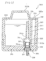
As shown in Fig. 19, in the same manner as the first
embodiment, an ink cartridge 200 of the second embodiment has:
a cartridge body 201 having an ink storing space 210 which stores
the ink I; a cover member 202 which covers the lower end of the
cartridge body 201; and a valve mechanism 203 that can open and
close both an ink path 240 (the solid arrows in Fig. 22) through
which the ink is supplied to the inkjet head 2, and an atmospheric
air path 241 (the broken arrow in Figs. 21 and 22) through which
atmospheric air is introduced into the ink storing space 210.
In the same manner as the embodiment described above, an ink
supply pipe 230 is protrudingly disposed in the attaching portion
4.
In the cartridge body 201, a partition wall 212 is formed
to vertically separate the ink storing space 210 which is
substantially hermetically sealed to store the ink I, from an
atmospheric air introducing space 211 into which atmospheric
air is introduced from the outside. Two tubes 213, 214 which
elongate toward the ink storing space 210, and which have different
lengths are formed integrally with the partition wall 212. The
upper half 217a of a valve housing hole 217 which will be described
later is formed in the shorter tube 213, and an ink introducing
hole 213a through which the ink I in the ink storing space 210
is introduced into the valve housing hole 217 is formed in an
upper wall portion of the tube 213.
By contrast, the longer tube 214 elongates to the vicinity
of a top plate of the cartridge body 201, and guides the atmospheric
air in the atmospheric air introducing space 211 to an upper
portion of the ink storing space 210.
The cover member 202 is fixed to a lower end portion of
the cartridge body 201 by welding or the like. The atmospheric
air introducing space 211 is defined by the cover member 202
and the partition wall 212. In the cover member 202, a tube 215
which elongates toward the atmospheric air introducing space
211 is formed at a position corresponding to the tube 213. The
tube 215 forms the lower half 217b of the valve housing hole
217. An atmospheric air communicating hole 215a through which
the valve housing hole 217 (217b) communicates with the
atmospheric air introducing space 211 is formed in a side portion
of the tube 215. An insertion hole 216 which communicates with
the lower half 217b of the valve housing hole 217 is formed in
the cover member 202.
The valve mechanism 203 has: the valve housing hole 217
(217a, 217b) which constitutes parts of the ink path 240 and
the atmospheric air path 241; an elastic valve member 220 which
is made of synthetic rubber or the like; and a valve element
221 (first opening-closing portion) which is made of a synthetic
resin or the like, and which is housed in the valve member 220.
The valve member 220 has: a valve seat portion 222 having a through
hole 222a into which the ink supply pipe 230 is to be inserted;
an urging portion 223 (urging member) which is placed above the
valve seat portion 222; and an atmospheric air path
opening-closing portion 224 (second opening-closing portion)
which is placed below the valve seat portion 222. The valve seat
portion 222, the urging portion 223, and the atmospheric air
path opening-closing portion 224 (second opening-closing
portion) are integrally configured.
An outer peripheral portion of the valve member 220 is
clamped between the partition wall 212 and the tube 215, whereby
the valve member is fixed.
The valve seat portion 222 is formed into a substantially
horizontal plate-like shape. The through hole 222a into which
the ink supply pipe 230 is to be inserted is formed in a middle
portion of the valve seat portion 222. The urging portion 223
has: a cylindrical side wall portion 223a which rises from an
outer peripheral side portion of the valve seat portion 222;
and a projected portion 223b which is radially inward projected
integrally from the upper end of the side wall portion 223a.
The lower face of the projected portion 223b butts against the
valve element 221 housed inside the urging portion 223, and the
valve element 221 is downward urged by the elastic forces of
the side wall portion 223a and the projected portion 223b. An
opening 223c constituting a part of the ink path 240 is formed
inside the projected portion 223b.
The atmospheric air path opening-closing portion 224
downward protrudes so as to be continuous to the through hole
222a of the valve seat portion 222, and is formed into a cylindrical
shape inwhich the diameter is larger as further downwardadvancing.
As shown in Fig. 20, in a state where the ink supply pipe 230
is not inserted into the through hole 222a, the lower end of
the atmospheric air path opening-closing portion 224 butts
against the cover member 202 to close apathbetween the atmospheric
air communicating hole 215a and the insertion hole 21.6, i.e.,
the atmospheric air path 241. By contrast, as shown in Figs.
21 and 22, in a state where the ink supply pipe 230 is inserted
into the through hole 222a, a lower end portion of the atmospheric
air path opening-closing portion 224 is elastically deformed
in a direction along which the lower end portion of the
opening-closing portion 224 is separated from the cover member
202, whereby the atmospheric air path 241 is opened.
The valve element 221 has: a basal portion 221a which butts
against the valve seat portion 222; and a valve side wall portion
221b having a short cylindrical shape which upward extends from
an outer peripheral side portion of the basal portion 221a. A
pressing face 221c which is pressed in an upward direction (along
which the ink path is opened) by the tip end of the ink supply
pipe 230, and an annular projection 221d which is projected toward
the valve seat portion 222 are formed on the lower face (the
end face opposed to the valve seat portion 222) of the basal
portion 221a. The valve element 221 is urged toward the valve
seat portion 222 by the urging portion 223. In a state where
the annular projection 221d is in close contact with the upper
face of the valve seat portion 222, the through hole 222a of
the valve seat portion 222 is blocked by the valve element 221,
and the ink path 240 is closed. A communicating hole 221e which
allows upper and lower spaces of the valve element 221 to
communicate with each other is formed in a portion of the basal
portion 221a which is outside the annular projection 221d and
inside the valve side wall portion 221b.
When the ink supply pipe 230 is inserted into the through
hole 222a during a process of attaching the ink cartridge 200
as shown in Fig. 23, the valve element 221 is pushed up against
the urging force of the urging portion 223 by the tip end of
the ink supply pipe 230, to be upward moved while deforming the
urging portion 223. As a result, the annular projection 221d
of the valve element 221 is separated from the valve seat portion
222, and the ink path 240 is opened.
The ink supply pipe 230 of the inkjet printer has a
small-diameter portion 231 which is on the side of the tip end,
and a large-diameter portion 232. A tapered portion 233
(operating portion) through which the small-diameter portion
231 is continuously connected to the large-diameter portion 232
is disposed integrally on an outer peripheral portion of the
ink supply pipe 230. An ink inflow port 231a which allows the
inner path of the ink supply pipe 230 to communicate with the
outside is formed in the tip end of the small-diameter portion
231.
Next, the opening and closing operations of the valve
mechanism 203 which are conducted during the processes of
attaching and detaching the ink cartridge 200 will be described.
As shown in Fig. 20, in a state where the ink cartridge
200 has not yet been attached to the inkjet printer, first, the
valve element 221 is downward urged by the urging force of the
urging portion 223 to butt against the upper face of the valve
seat portion 222, so that the annular projection 221d is in close
contact with the valve seat portion 222. As a result, the through
hole 222a is closed by the valve element 221, and the ink path
240 is closed. Moreover, the lower end of the atmospheric air
path opening-closing portion 224 butts against the cover member
202, and also the atmospheric air path 241 is closed by the
atmospheric air path opening-closing portion 224.
When, in this state, the ink supply pipe 230 is inserted
through the insertion hole 216 into the cartridge body 201, the
small-diameter portion 231 of the ink supply pipe 230 is first
inserted into the through hole 222a as shown in Fig. 21, and
the tapered portion 233 butts against a root portion of the
atmospheric air path opening-closing portion 224. In accordance
with the operation of inserting the ink supply pipe 230, the
atmospheric air path opening-closing portion 224 is pushed up
by the tapered portion 233, and the lower end of the atmospheric
air path opening-closing portion 224 is separated from the cover
member 202. Therefore, the atmospheric air path 241 which
elongates from the insertion hole 216 to the atmospheric air
communicating hole 215a and the atmospheric air introducing space
211 is opened.
When the ink supply pipe 230 is further inserted, the tip
end of the ink supply pipe 230 butts against the pressing face
221c formed in the basal portion 221a of the valve element 221
to push up the valve element 221 as shown in Fig. 22. At this
time, the valve side wall portion 221b of the valve element 221
pushes up the projected portion 223b of the urging portion 223,
and the projected portion 223b and the side wall portion 223a
are elastically deformed. Therefore, the valve element 221 is
upward moved against the urging force of the urging portion 223.
As a result, the valve element 221 is separated from the upper
face of the valve seat portion 222 to open the through hole 222a,
and the tip end portion of the ink supply pipe 230 upward protrudes
from the through hole 222a. Therefore, the ink path 240 which
elongates from the ink introducing hole 213a to the through hole
222a via the valve housing hole 217, the opening 223c, and the
communicating hole 221e, so that the ink path 240 communicates
with the ink supply pipe 230 and the ink I is supplied to the
ink supply pipe 230. At this time, the valve seat portion 222
is in close contact with the outer peripheral portions of the
small-diameter portion 231 and the tapered portion 233 of the
ink supply pipe 230, thereby preventing the ink I flowing through
the ink path 240 from leaking from a portion between the ink
supply pipe 230 and the valve seat portion 222.
By contrast, in the case where the ink cartridge 200 is
to be detached from the inkjet printer, when the ink supply pipe
230 is extracted from the cartridge body 201, the valve element
221 is downward urged by the urging force of the urging portion
223 to butt against the valve seat portion 222, and the through
hole 222a is closed, whereby the ink path 240 is closed. Moreover,
the lower end of the atmospheric air path opening-closing portion
224 is caused by the elasticity of the portion itself to butt
against the cover member 202, and hence also the atmospheric
air path 241 is closed.
In the ink cartridge 200, the valve mechanism has a valve
seat portion which is disposed in the cartridge body, and in
which a through hole is formed, the ink supply pipe being to
be inserted into the through hole, the first opening-closing
portion is buttable against the valve seat portion from a side
of the ink storing space of the cartridge body, to close the
through hole, a part of the atmospheric air path is formed on
a side opposite to the ink storing space across the valve seat
portion, and the second opening-closing portion is disposed to
be enabled to open and close the part of the atmospheric air
path. When the ink supply pipe is attached to the cartridge body,
therefore, the through hole is openedby the first opening-closing
portion, so that the ink is supplied to the ink supply pipe passed
through the through hole, and a part of the atmospheric air path
is opened by the second opening-closing portion, so that
atmospheric air is introduced into the ink storing space.
In the ink cartridge 200, the second opening-closing
portion protrudes from the valve seat portion to the side opposite
to the ink storing space, and is disposed integrally with the
valve seat portion, and the second opening-closing portion is
elastically deformable in a direction along which the atmospheric
air path is opened and closed. When the second opening-closing
portion which is disposed integrally with the valve seat portion
is elastically deformed, therefore, the part of the atmospheric
air path which is formed on the side opposite to the ink storing
space across the valve seat portion is opened or closed.
In the ink cartridge 200, in a state where the ink supply
pipe is inserted into the through hole, an inner peripheral face
of the through hole is in close contact with an outer face of
the ink supply pipe. As described above, when the ink supply
pipe is inserted into the through hole, the inner peripheral
face of the through hole is in close contact with the outer face
of the ink supply pipe. During the process of supplying the ink
from the ink path to the ink supply pipe, therefore, the ink
can be prevented from flowing to the outside.
Next, a third embodiment of the invention will be described.
As shown in Fig. 23, an ink cartridge 300 of the third
embodiment has: a cartridge body 301 having an ink storing space
310 which stores an ink; a cover member 302 which covers an upper
portion of the cartridge body 301; a cap 303 which is disposed
on the a lower end portion of the cartridge body 301; and a valve
mechanism 304 that can open and close both an ink path 340 (the
solid arrow in Fig. 26) through which the ink is supplied to
the inkjet head 2, and an atmospheric air path 341 (the broken
arrows in Fig. 26) through which atmospheric air is introduced
into the ink storing space 310. Each of the cartridge body 301,
the cover member 302, and the cap 303 is made of a synthetic
resin.
A wall portion 312 which vertically extends is formed in
a right portion of the cartridge body 301 in Fig. 23. The wall
portion 312 separates the internal space of the cartridge body
301 into an atmospheric air introducing space 311 on the right
side and an ink storing space 310 on the left side. The atmospheric
air introducing space 311 communicates with the outside through
an atmospheric air introducing port 302a formed in the cover
member 302. In the ink storing space 310, disposed are a tube
314 which upward protrudes from a bottom wall portion 313 of
the cartridge body 301, and a tube 315 which further upward
protrudes from the upper end of the tube 314.
A tip end portion of the tube 315 is higher than the ink
level in the ink storing space 310.
The cover member 302 is fixed to an upper end portion of
the cartridge body 301 by ultrasonic welding or the like. A knob
302b which upward protrudes is disposed in the cover member 302.
The atmospheric air introducing port 302a for introducing
atmospheric air into the atmospheric air introducing space 311
is formed in the cover member 302. A gas permeable membrane 316
which does not allow liquid to permeate the membrane and allows
only a gas (atmospheric air) to permeate it is disposed in the
atmospheric air introducing port 302a.
The cap 303 is fixed to the cartridge body 301 by ultrasonic
welding or the like so as to cover a lower end portion of the
cartridge body 301. An insertion hole 317 which communicates
with a valve housing hole 320 of the cartridge body 301, and
into which the ink supply pipe 330 is to be inserted is formed
in the cap 303. The diameter of the insertion hole 317 is smaller
than that of the lower end of the valve housing hole 320.
As shown in Figs. 24 to 27, the valvemechanism 304 comprises:
the valve housing hole 320 which constitutes parts of the ink
path 340 and the atmospheric air path 341; and a valve member
321 which is slidably attached into the valve housing hole 320.
The valve housing hole 320 is formed by the tube 314 and the
bottom wall portion 313. The valve housing hole 320 has: a
straight hole portion 320a; and a tapered hole portion 320b which
is continuous to the lower end of the straight hole portion 320a,
and in which the diameter is larger as further downward advancing.
The valve housing hole 320 communicates with a lower portion
of the ink storing space 310 through a communicating hole 314a
(first communicating hole) formed in a side wall portion of the
tube 314. The valve housing hole 320 communicates also with an
upper portion of the ink storing space 310 through a communicating
hole 314b (third communicating hole) formed in an upper wall
portion of the tube 314, and the tube 315. Furthermore, the valve
housing hole 320 communicates with the atmospheric air
introducing space 311 through a communicating hole 312a (fifth
communicating hole) formed in the wall portion 312.
The valve member 321 is made of a material which is
elastically deformable, such as synthetic rubber, and formed
into a substantially cylindrical shape in which both the ends
are opened. A lower end portion of the valve member 321 is formed
into tapered shape in which the diameter is larger as further
downward advancing. First, second, third, and fourth sealing
portions 321a, 321b, 321c, and 321d which annularly outward
protrude to be in close contact with the inner face of the valve
housing hole 320 are disposed on outer peripheral portions of
upper and lower end portions, and middle portions of the valve
member 321, respectively. A horizontal butting portion 322
against which the tip end of the ink supply pipe 330 is to butt
is formed inside a portion between the second and third sealing
portions 321b and 321c. Inside the tapered lower end portion
ofthevalvemember321, anengagingportion323whichisengageable
with a flange portion 330a formed in a tip end portion of the
ink supply pipe 330 is formed so as to inward protrude in a rib-like
shape. The lower end portion of the valve member 321 including
the engaging portion 323 is configured so as to be elastically
deformable in the diameter-decreasing direction. Alternatively,
the engaging portion 323 may be configured so as to annularly
protrude. Alternatively, plural engaging portions 323 may be
discretely formed at equal circumferential intervals on the inner
face of the valve member 321.
A communicating hole 324 (second communicating hole) which
allows the valve housing hole 320 and an internal space 326 of
the valve member 321 to communicate with each other is formed
in a portion between the third and fourth sealing portions 321c
and 321d. A communicating hole 325 (fourth communicating hole)
which allows an internal space 327 of the valve member 321 and
the valve housing hole 320 to communicate with each other is
formed in a portion which is between the second and third sealing
portions 321b and 321c, and which is higher in level than the
butting portion 322. The internal space 326 communicating with
the communicating hole 324 (second communicating hole) , and the
internal space 327 communicating with the communicating hole
325 (fourth communicating hole) are vertically separated from
each other by the butting portion 322 (partition wall).
As shown in Figs. 24 and 25, two ribs 328 which vertically
elongate between the first and third sealing portions 321a and
321c are formed on an outer peripheral portion of the valve member
321, at positions which are symmetric about the center axis of
the valve member 321. In the space between the valve member 321
and the valve housing hole 320, the two ribs 328 separate a space
350 which communicates with the communicating hole 314a, and
into which the ink flows from a space 351 which communicates
with the communicating hole 312a, and into which atmospheric
air flows. The two ribs 328 are engaged with two vertical grooves
352 which are formed in the inner face of the valve housing hole
320, respectively, thereby preventing the valve member 321 from
being rotated in the valve housing hole 320 when the valve member
321 is moved in the valve housing hole 320.
As shown in Fig. 24, the ink supply pipe 330 is made of
a synthetic resin, and, in the same manner as the embodiments
described above, protrudingly disposed in the attaching portion
4. A flange portion 330a is formed in a tip end portion of the
ink supply pipe 330. An ink inflow port 330b which allows the
inner path of the ink supply pipe 330 to communicate with the
outside is formed in the vicinity of the flange portion 330a.
The flange portion 330a constitutes an operating portion which
slidingly operates the valve member 321 as described later.
Next, the opening and closing operations of the valve
mechanism 304 which are conducted during the processes of
attaching and detaching the ink cartridge 300 will be described.
As shown in Fig. 24, in a state where the ink cartridge
300 has not yet been attached to the inkjet printer, first, the
valve member 321 is positioned near the insertion hole 317 in
the valve housing hole 320, and the lower end portion of the
valve member 321 is placed inside the tapered hole portion 320b
of the valve housing hole 320, and increased in diameter. The
communicating hole 314a communicating with the ink storing space
310 is placed between the second and third sealing portions 321b
and 321c, whereby the ink path 340 is closed. Moreover, the
communicating hole 312a communicating with the atmospheric air
introducing space 311 is placed between the first and second
sealing portions 321a and 321b, whereby also the space in the
tube 315, i. e., the atmospheric air path 341 is closed with respect
to the communicating hole 312a. At this time, although both the
communicating hole 314a on the side of the ink storing space
310, and the communicating hole 325 on the atmospheric air
introduction side are positioned between the second and third
sealing portions 321b and 321c, the ink is prevented from flowing
into the communicating hole 325, by the two ribs 328 which block
communication between the holes.
When, in this state, the ink supply pipe 330 is inserted
through the insertion hole 317 into the cartridge body 301, the
flange portion 330a of the ink supply pipe 330 is inserted into
the internal space 326 without interfering with the engaging
portion 323 of the valve member 321 as shown in Fig. 26 because
the diameter of the lower end portion of the valve member 321
is increased. The upper face of the flange portion 330a of the
ink supply pipe 330 butts against the lower face of the butting
portion 322 of the valve member 321, and the valve member 321
is pushed up by the ink supply pipe 330 until the tubular member
butts against the upper wall portion of the tube 314. At this
time, the tapered lower end portion of the valve member 321 is
gradually elastically deformed in the diameter-decreasing
direction along the tapered hole portion 320b, and the fourth
sealing portion 321d formed in the lower end portion of the valve
member 321 is in close contact with the straight hole portion
320a.
Moreover, the engaging portion 323 is in close contact
with the outer periphery of the ink supply pipe 330 to seal the
lower internal space 326 with respect to the outside, and the
internal space communicates with the ink inflow port 330b.
The communicating hole 314a communicating with the ink
storing space 310 is placed between the third and fourth sealing
portions 321c and 321d, and the communicating hole 324 of the
valve member 321 communicates with the communicating hole 314a
of the tube 314. Namely, the ink path 340 which elongates from
the ink storing space 310 to the internal space 326 of the valve
member 321 via the communicating hole 314a, the valve housing
hole 320, and the communicating hole 324 is opened, and the ink
path 340 communicates with the ink supply pipe 330 through the
ink inflow port 330b. At the same time, the communicating hole
312a communicating with the atmospheric air introducing space
311 is placed between the second and third sealing portions 321b
and 321c, and the communicating hole 325 of the valve member
321 communicates with the communicating hole 312a of the wall
portion 312. Namely, the atmospheric air path 341 which elongates
from the tube 315 to the communicating hole 312a via the upper
internal space 327 of the valve member 321, the communicating
hole 325, and the valve housing hole 320 in the outer periphery
of the valve member 321 is opened to the outside. Therefore,
atmospheric air is introduced from the atmospheric air
introducing space 311 into the upper portion of the ink storing
space 310, and the ink I in the ink storing space 310 is supplied
to the ink supply pipe 330. At this time, as shown in Fig. 26,
the internal space 326 which communicates with the communicating
hole 314a, and into which the ink flows is separated from the
internal space 327 which communicates with the communicating
hole 312a, and into which the atmospheric air flows, by the
partition wall formed by the butting portion 322. Therefore,
the ink does not flow into the internal space 327.
By contrast, in the case where the ink cartridge 300 is
to be detached from the inkjet printer, when the ink supply pipe
330 is extracted from the cartridge body 301, the flange portion
330a of the ink supply pipe 330 is engaged with or butts against
the engaging portion 323 formed in the lower end portion of the
valve member 321 as shown in Fig. 27. Therefore, the valve member
321 is downward moved integrally with the ink supply pipe 330.
As the engaging portion 323 is further moved along the tapered
hole portion 320b, however, the engaging portion is gradually
further elastically deformed in the diameter-increasing
direction to return to its original shape. Therefore, the
engagement state between the engaging portion 323 and the flange
portion 330a is cancelled, and the valve member 321 is engagingly
held by the cover member 302, so that only the ink supply pipe
330 is extracted to the outside of the cartridge body 301.
In the ink cartridge300, the valve mechanism has: a valve
housing hole which is formed in the cartridge body 301, and which
constitutes parts of the ink path and the atmospheric air path;
and the valve member in which the first and second opening-closing
portions are formed into an integral cylindrical shape, and into
which a tip end portion of the ink supply pipe is to be inserted,
the valve member is slidably attached into the valve housing
hole, and the valve member has: a butting portion against which,
when a tip end portion of the ink supply pipe is inserted into
the valve member, a tip end of the ink supply pipe butts to move
the valve member in a direction along which the ink path and
the atmospheric air path are opened; and an engaging portion
with which, when the ink supply pipe is extracted, the tip end
portion of the ink supply pipe is engaged to move the valve member
in a direction along which the ink path and the atmospheric air
path are closed.
In the ink cartridge 300, when the tip end portion of the
ink supply pipe is inserted into the tubular valve member, the
tip end of the ink supply pipe butts against the butting portion
of the valve member, and, in conjunction with the operation of
inserting the ink supply pipe, the valve member is moved to open
the ink path and the atmospheric air path. By contrast, when
the ink supply pipe is extracted from the valve member, the tip
end portion of the ink supply pipe is engaged with the engaging
portion of the valve member, and, in conjunction with the operation
of detaching the ink supply pipe, the valve member is moved to
close the ink path and the atmospheric air path.
In the ink cartridge 300, the engaging portion is disposed
in an end portion of the valve member on a side into which the
ink supply pipe is to be inserted, and the engaging portion is
elastically deformable in a diameter-increasing or
diameter-decreasing direction of the valve member. By means of
the configuration in which the diameter of the engaging portion
disposed in the end portion of the valve member can be increased
or decreased as described above, the ink supplypipe can be inserted
into or extracted from the valve member.
In the ink cartridge 300, the ink path has: a first
communicating hole which allows the ink storing space in the
cartridge body and the valve housing hole to communicate with
each other; and a second communicating hole which allows the
valve housing hole and the internal space of the valve member
to communicate with each other, the atmospheric air path has:
a third communicating hole which allows an outside of the cartridge
body and the valve housing hole to communicate with each other;
a fourth communicating hole which allows the valve housing hole
and the internal space of the valve member to communicate with
each other; and a fifth communicating hole which allows the valve
housing hole and the ink storing space in the cartridge body
to communicate with eachother, and the valvemember has apartition
wall which, in the internal space, separates a portion
communicating with the second communicating hole from a portion
communicating with the fourth communicating hole.
The ink stored in the ink storing space of the cartridge
body flows into the valve housing hole through the first
communicating hole. Thereafter, the ink enters the internal
space of the valve member through the second communicating hole,
and then flows from the internal space to the ink supply pipe.
The atmospheric air outside the cartridge body flows into the
valve housing hole through the third communicating hole.
Thereafter, the atmospheric air enters the internal space of
the valve member through the fourth communicating hole, and then
flows into the ink storing space through the fifth communicating
hole. In the internal space of the valve member, the portion
into which the ink is to flow from the second communicating hole
is separated by the partition wall from that into which atmospheric
air is to flow from the fourth communicating hole. Therefore,
the atmospheric air does not enter the ink path, and the ink
does not enter the atmospheric air path.
Next, a modification of the third embodiment will be
described. An ink cartridge of the modification is different
from the third embodiment in the shape of the valve member. In
the following description, the components which are configured
in the same manner as those of the third embodiment are denoted
by the same reference numerals, and their description is often
omitted.
As shown in Fig. 28, in the same manner as the third
embodiment, an ink cartridge 300E comprises: the cartridge body
301; the cover member 302; the cap 303; and a valve mechanism
304E disposed in the cartridge body 301.
The valve mechanism 304E has: the valve housing hole 320
formed in the cartridge body 301; and a valve member 321E which
is attached to the valve housing hole 320 so as to be vertically
slidable. The valve housing hole 320 has: the straight hole
portion 320a; and the taperedhole portion 320bwhich is continuous
to the lower end of the straight hole portion 320a, and in which
the diameter is larger as further downward advancing.
The valve member 321E housed in the valve housing hole
320 has a substantially cylindrical shape. Unlike in the valve
member 321 of the third embodiment, a lower end portion of the
valve member 321E is not formed into a tapered shape. In the
same manner as the third embodiment, the first, second, third,
and fourth sealing portions 321a, 321b, 321c, and 321d are formed
on the outer peripheral portion of the valve member 321E. The
butting portion 322 against which a flange portion 360 of an
ink supply pipe 330E is to butt is formed inside the valve member
321E.
An engaging portion 323E which inward protrudes is formed
inside a lower end portion of the valve member 321E. When the
ink supply pipe 330E is inserted into the valve member 321E,
and when the ink supply pipe 330E is extracted from the valve
member 321E, a lower end portion including the engaging portion
323E is expanded by the flange portion 360 of the ink supply
pipe 330E so that the lower end portion is slightly elastically
deformable in the diameter-increasing direction. In order to
enable the flange portion 360 to be smoothly inserted into and
extracted from the valve member 321E, preferably, tapered
portions 323a, 323b are formed in upper and lower sides of an
inner portion of the engaging portion 323E as shown in Fig. 29,
and tapered portions 360a, 360b are formed in upper and lower
sides of an outer portion of the flange portion 360 of the ink
supplypipe 330E. Alternatively, the taperedportions 323a, 323b
or 360a, 360b may be disposed in only one of the engaging portion
323E and the flange portion 360.
When the ink supply pipe 330E is inserted into the cartridge
body 301 of the ink cartridge 300E, the engaging portion 323E
is expanded by the flange portion 360 of the ink supply pipe
330E to be elastically deformed in the diameter-increasing
direction, and the flange portion 360 is inserted into the internal
space of the valve member 321E. In the same manner as the third
embodiment, the flange portion 360 then butts against the butting
portion 322 to push up the valve member 321E, whereby the ink
path and the atmospheric air path are opened.
By contrast, when the ink supply pipe 330E is extracted
from the cartridge body 301, the flange portion 360 is engaged
with the engaging portion 323E, and the ink supply pipe 330E
and the valve member 321E are integrally downward moved, whereby
the ink path and the atmospheric air path are closed. When the
lower end of the valve member 321E butts against the cap 303,
the engaging portion 323E is expanded by the flange portion 360
to be elastically deformed in the diameter-increasing direction,
and the flange portion 360 is extracted from the valve member
321E.
In the modification, the engaging portion 323E is
elastically deformable in the diameter-increasing direction in
the tapered hole portion 320b of the valve housing hole 320.
It is not necessary to form the valve housing hole into a tapered
shape. It is requested only that at least the inner diameter
of the lower end portion of the valve housing hole is partially
increased.
In the third embodiment and the modification, as described
above, the positional relationships among the communicating holes
314a, 312a and the first to fourth sealing portions 321a to 321d
in the sliding direction of the valve member 321 or 321E are
adequately set, whereby the atmospheric air path can be opened
faster than the ink path when the ink cartridge is attached to
the inkjet printer.