EP1520536A1 - Device for the application of acoustic shockwaves - Google Patents
Device for the application of acoustic shockwaves Download PDFInfo
- Publication number
- EP1520536A1 EP1520536A1 EP03022056A EP03022056A EP1520536A1 EP 1520536 A1 EP1520536 A1 EP 1520536A1 EP 03022056 A EP03022056 A EP 03022056A EP 03022056 A EP03022056 A EP 03022056A EP 1520536 A1 EP1520536 A1 EP 1520536A1
- Authority
- EP
- European Patent Office
- Prior art keywords
- shock wave
- focusing
- shock
- wave generating
- shock waves
- Prior art date
- Legal status (The legal status is an assumption and is not a legal conclusion. Google has not performed a legal analysis and makes no representation as to the accuracy of the status listed.)
- Withdrawn
Links
Images
Classifications
-
- A—HUMAN NECESSITIES
- A61—MEDICAL OR VETERINARY SCIENCE; HYGIENE
- A61B—DIAGNOSIS; SURGERY; IDENTIFICATION
- A61B17/00—Surgical instruments, devices or methods, e.g. tourniquets
- A61B17/22—Implements for squeezing-off ulcers or the like on the inside of inner organs of the body; Implements for scraping-out cavities of body organs, e.g. bones; Calculus removers; Calculus smashing apparatus; Apparatus for removing obstructions in blood vessels, not otherwise provided for
- A61B17/225—Implements for squeezing-off ulcers or the like on the inside of inner organs of the body; Implements for scraping-out cavities of body organs, e.g. bones; Calculus removers; Calculus smashing apparatus; Apparatus for removing obstructions in blood vessels, not otherwise provided for for extracorporeal shock wave lithotripsy [ESWL], e.g. by using ultrasonic waves
- A61B17/2255—Means for positioning patient, shock wave apparatus or locating means, e.g. mechanical aspects, patient beds, support arms, aiming means
-
- A—HUMAN NECESSITIES
- A61—MEDICAL OR VETERINARY SCIENCE; HYGIENE
- A61B—DIAGNOSIS; SURGERY; IDENTIFICATION
- A61B17/00—Surgical instruments, devices or methods, e.g. tourniquets
- A61B17/22—Implements for squeezing-off ulcers or the like on the inside of inner organs of the body; Implements for scraping-out cavities of body organs, e.g. bones; Calculus removers; Calculus smashing apparatus; Apparatus for removing obstructions in blood vessels, not otherwise provided for
- A61B17/22004—Implements for squeezing-off ulcers or the like on the inside of inner organs of the body; Implements for scraping-out cavities of body organs, e.g. bones; Calculus removers; Calculus smashing apparatus; Apparatus for removing obstructions in blood vessels, not otherwise provided for using mechanical vibrations, e.g. ultrasonic shock waves
-
- A—HUMAN NECESSITIES
- A61—MEDICAL OR VETERINARY SCIENCE; HYGIENE
- A61N—ELECTROTHERAPY; MAGNETOTHERAPY; RADIATION THERAPY; ULTRASOUND THERAPY
- A61N7/00—Ultrasound therapy
Definitions
- the invention relates to a device, in particular a Therapy device for the application of acoustic Shock waves according to the preamble of claim 1.
- Such therapy devices for the application of For example, acoustic shock waves are used for the Lithotripsy or in orthopedics for human applications used. Likewise, the therapy devices come in the Veterinary medicine is used.
- the area to be treated is located and applied a required number of acoustic shock waves.
- the area to be treated can be located at different distances from the body surface of the patient. This distance depends on the one hand on the type of area to be treated (kidney stones, soft tissue structures), on the other hand on the constitution of the patient (obese / not obese).
- the penetration depth of the acoustic shock waves is defined by the location of the shock wave generation and the geometry of the shock wave focusing device.
- shock wave focus In positioning the shock wave focus in the respective various low-lying therapeutic areas in the body of the Patients are therapy devices with different strengths or variable penetration depths required.
- From DE 197 18 511 C2 is a device of the initially genus known in the various hand-held Therapy heads with different penetration depths detachable with a supply unit can be connected. Here too no stepless adjustment of the penetration depth is possible. For different applications, the therapy heads need each to be exchanged.
- the object is based on a device of the beginning genus to improve so that a high Flexibility in the application a quick and easy Positioning of the shockwave focus in the therapy area achieved a low transmission loss of the shock waves becomes.
- the essential idea of the invention is a Device for the application of acoustic shock waves, the to a region of a human or to be treated animal body are directed, consisting of a housing with at least one coupling surface for coupling the Shock waves in the body to be treated, with a Shock wave generating device and one for focusing the shock waves suitable means to perform so that the Shock wave generating device with the for focusing the Shock waves suitable means in the housing relative to Coupling surface is designed to be movable.
- the position of the shock wave generating device together with the means suitable for focusing the shock waves is according to the invention in the housing relative to the coupling surface variable.
- the Shock wave generating device together with the Focusing the shock waves suitable means on a first axis that of the shock wave generating device through the coupling surface to one of which for focusing the Shock waves suitable means generated shock wave focus runs, formed movable.
- the shock wave generating device together with the Focusing the shock waves suitable means of inventive device in the direction of coupling surface is the penetration depth of the shock waves in the treated Patient varies and may affect the area to be treated be set.
- the housing with the coupling surface is opposite the shock wave generating device and to the Focusing the shock waves suitable means stationary arranged.
- the inventive device can be without a Use of accessories the penetration depth of the shock waves in the body of the patient and thus the depth of focus with a and the same device vary continuously.
- the coupling surface in a preferred manner of a Coupling membrane is formed, does not have to be moved and is therefore subject to no wear and no premature Aging.
- the Shock wave generating device together with the Focusing the shock waves suitable means on at least a second axis at an angle with the first axis forms, formed movable.
- the shock wave focus faster into the area to be treated in the body of the patient position, on the other hand, a larger area in the body of the Treat patients without the need for the patient, a patient support device or the Therapy device to move.
- a patient support device or the Therapy device to move.
- the shock wave focus on three-dimensional axes to move along a fracture.
- the shock wave generating device is fastened together with the means suitable for focusing the shock waves at a point in the housing and designed to be movable such that the shock wave generating device can be tilted together with the means suitable for focusing the shock waves around this point.
- the shock wave generating device can also be moved together with the means suitable for focusing the shock waves means in the direction of the coupling surface and simultaneously or sequentially tilted in different directions. With the described movements, the shock wave focus can be moved within a three-dimensional therapeutic area in the body of the patient.
- the movement of the shock wave generating device together with suitable for focusing the shock waves means both manually and electro-mechanically via a electric drive.
- the position of the shock wave generating device together with the means suitable for focusing the shock waves The first axis can be detected and thus the penetration depth of Shock waves in the patient's body and the location of the patient Shock wave focus determined at a distance from the coupling surface and be displayed to the user.
- the display can be made by means of a numeric scale on the outside of the case or above an electrical display.
- a display unit of the therapy device are displayed. This allows rapid treatment positioning of the therapy device at treatment sites located in the immediate vicinity of the patient.
- an operating unit for the electromechanical Movement of the shock wave generating device with the means suitable for focusing the shock waves and thus for the positioning of the shock wave focus in the Therapy area provided. This is the handiness of Therapy device further increased.
- the movement of the Shock wave generating device and the for focusing the Shock waves suitable means with an imaging system be coupled.
- the movement of the Shock wave generating device with the for focusing the Shock waves suitable means of positioning the Shock wave focus into the corresponding therapeutic area successful localization with the imaging system preferably automatically.
- the flexibility of the device has increased significantly in the form of an increase in the possibilities of use.
- the shock wave generation of the shock wave generating device is based in a preferred embodiment on the electro-hydraulic principle.
- the generation of the shock waves can also be effected, for example, electromagnetically or piezoelectrically.
- the focusing is realized in a conventional manner with a reflector.
- the shock waves by reflectors they can be designed as half-shell-shaped ellipsoids or paraboloids with different axis ratios.
- acoustic lenses with different focal lengths can be used.
- half-shell-shaped arrangements of electrical membranes or piezocrystal elements with different diameters can be used.
- the means suitable for focusing the shock waves means the maximum penetration depth of the shock waves is defined.
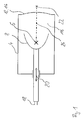
- FIG. 1 shows the Inventive device in a first embodiment in a side view.
- a housing 4 forms with a Coupling membrane 14 a closed volume by a for the propagation of shock waves suitable medium 16th is introduced.
- the coupling membrane 14 forms in the illustrated embodiment, the coupling surface 12 of Therapy device for coupling the shock waves in the zu treating body.
- a Shock wave generating device 6 In the housing 4 are a Shock wave generating device 6, the at least one Supply line 18 is operated and one for the Focusing the shock waves suitable means 8, below Focusing device 8 called.
- the shock wave generating device 6 and the Focusing device 8 are together on a first Axis 24 movably arranged, which of the Shock wave generating device 6 through the coupling membrane fourteenth to one generated by the focusing device 8 Shock wave focus 22 runs.
- An axial movement 20 of the Shock wave generating device 6 together with the Focusing device 8 is based on the stationary Housing 4 in and opposite to the direction of the coupling surface 12th
- the distance of the shock wave generating device 6 with the Focusing device 8 to the coupling surface 12 can be varied become.
- the distance of the shock wave generating device 6 to the shock wave focus 22 is determined by the geometry of the Focusing device 8 determined.
- By the variation of the Distance of the focusing device 8 together with the Shock wave generating device 6 to the coupling surface 12 is the depth of penetration of shock waves in the body of the patient and so that the position of the shock wave focus 22 changes.
- a movement 20 of the shock wave generating device 6 together with the focusing device 8 in the housing 4 can manually, electro-mechanically or hydraulically by means of a electrical or hydraulic drive.
- the operating principle of the shock wave generating device 6 is based in the illustrated embodiment on the electro-hydraulic Principle.
- shock wave generating device 6 and the Focusing device 8 with a second membrane second closed volume, which is within the Volume is through the housing 4 and the Coupling membrane 14 is generated.
- this second volume can conductive particles to promote sparkover are introduced, as known from EP 0 781 447 B1.
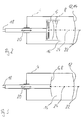
- shock waves can also be generated in other ways be such as with an electromagnetic or piezoelectric shock wave generating device 6, which in a respective further embodiment of the invention in the Figures 2 and 3 are shown.
- a membrane of a flat coil forms the Shock wave generating device 6.
- the generated Shock waves are by means of an acoustic lens. 8 focused.
- the Shock waves by means of dome-shaped piezo elements generated.
- the shape of the shock wave generating device 6 in this case forms the focusing device 8.
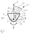
- FIG. 1 An advantageous embodiment of inventive device is that in the Housing 4, which is not explicitly shown in the figure is the shock wave generating device 6 with the Focusing device 8 in addition to the movement 20 on the first axis 24 on a second axis 26 simultaneously or is movable in succession.
- This can be advantageous Way the shock wave focus 22 in the area to be treated be positioned without a patient or, if required, a patient support device or the Therapy device to move.
- the second axis 26 forms with the first axis 24 an angle 28, which is preferably 90 ° is.
- the shock wave generating device 6 is fastened together with the focusing device 8 at a point 32 in the housing 4 and designed to be movable such that the shock wave generating device 6 together with the focusing device 8 can be tilted about this point 32.
- the tilt angle 34 may be displayed to the user.
- the main direction of the shock wave propagation thus takes place not only in a single direction but rather in different directions which describe a circular segment-shaped surface 30.
- the shock wave focus 22 is moved along the circumference of the circular segment-shaped surface 30.
- the shock wave generating device 6 may also together with the focusing device 8 in the direction of the coupling surface 12th moved and at the same time or successively in different Be tilted and tilted or sideways. With the described movements, the shock wave focus 22 within a three-dimensional therapeutic area in the body move the patient.
Abstract
Description
Die Erfindung betrifft eine Vorrichtung, insbesondere eine Therapievorrichtung zur Applikation von akustischen Stosswellen gemäss dem Oberbegriff des Anspruchs 1.The invention relates to a device, in particular a Therapy device for the application of acoustic Shock waves according to the preamble of claim 1.
Derartige Therapievorrichtungen zur Applikation von akustischen Stosswellen werden beispielsweise für die Lithotripsie oder in der Orthopädie für Humananwendungen eingesetzt. Ebenso kommen die Therapievorrichtungen in der Veterinärmedizin zum Einsatz.Such therapy devices for the application of For example, acoustic shock waves are used for the Lithotripsy or in orthopedics for human applications used. Likewise, the therapy devices come in the Veterinary medicine is used.
Hierbei wird der zu behandelnde Bereich lokalisiert und eine
erforderliche Anzahl akustischer Stosswellen appliziert. Der
zu therapierende Bereich kann dabei unterschiedlich weit von
der Körperoberfläche des Patienten entfernt liegen. Dieser
Abstand hängt einerseits von der Art des zu therapierenden
Bereiches (Nierensteine, Weichteilstrukturen), andererseits
von der Konstitution des Patienten (adipös/nicht adipös) ab.
Die Eindringtiefe der akustischen Stosswellen wird durch den
Ort der Stosswellenerzeugung und der Geometrie der
Stosswellenfokussierungseinrichtung definiert.Here, the area to be treated is located and applied a required number of acoustic shock waves. The area to be treated can be located at different distances from the body surface of the patient. This distance depends on the one hand on the type of area to be treated (kidney stones, soft tissue structures), on the other hand on the constitution of the patient (obese / not obese).
The penetration depth of the acoustic shock waves is defined by the location of the shock wave generation and the geometry of the shock wave focusing device.
Zur Positionierung des Stosswellenfokus in die jeweiligen verschieden tief gelegenen Therapiegebiete im Körper des Patienten sind Therapievorrichtungen mit verschieden festen oder variablen Eindringtiefen erforderlich.For positioning the shock wave focus in the respective various low-lying therapeutic areas in the body of the Patients are therapy devices with different strengths or variable penetration depths required.
Aus DE 195 09 004 C1 ist es bekannt, bei einer Vorrichtung der genannten Art austauschbare Koppelaufsätze wie beispielsweise Ankoppelpolster oder Koppelkissen zur Variierung des Abstandes zwischen der Stosswellenerzeugungseinrichtung und der Einkoppelfläche der Stosswellen in den Körper des Patienten vorzusehen, wodurch die Lage des Stosswellenfokus auf den zu therapierenden Bereich im Körper des Patienten angepasst werden kann. Eine schlechtere Energieübertragung der Stosswellen aufgrund einer zusätzlichen Koppelfläche ist dabei jedoch festzustellen. Zudem sind keine stufenlos einstellbaren Eindringtiefen, sondern nur entsprechend der Dicke der Ankoppelpolster bzw. Koppelkissen fest vorgegebene Eindringtiefen möglich. Zusätzlich gestaltet sich das Handling beim Aufsetzen der Koppelaufsätze aufwendig. From DE 195 09 004 C1 it is known in a device of mentioned type interchangeable coupling attachments such as Ankoppelpolster or coupling pad for varying the distance between the shock wave generating device and the Coupling surface of the shock waves in the body of the patient whereby the position of the shock wave focus on the adapted to the therapeutic area in the body of the patient can be. A worse energy transfer the Shock waves due to an additional coupling surface is included however, to determine. In addition, there are no infinitely adjustable Penetration depths, but only according to the thickness of the Ankoppelpolster or coupling pad firmly predetermined Penetration depths possible. In addition, the handling is designed consuming when attaching the coupling attachments.
Aus DE 197 18 511 C2 ist eine Vorrichtung der eingangs genannten Gattung bekannt, bei der verschiedene handgehaltene Therapieköpfe mit unterschiedlichen Eindringtiefen lösbar mit einer Versorgungseinheit verbunden werden können. Auch hier ist keine stufenlose Einstellung der Eindringtiefe möglich. Für unterschiedliche Anwendungen müssen die Therapieköpfe jeweils ausgetauscht werden.From DE 197 18 511 C2 is a device of the initially genus known in the various hand-held Therapy heads with different penetration depths detachable with a supply unit can be connected. Here too no stepless adjustment of the penetration depth is possible. For different applications, the therapy heads need each to be exchanged.
In DE 199 35 724 A1 wird ein Therapiegerät beschrieben, bei der die Koppelmembran zur Ankopplung der Vorrichtung an den Patienten flexibel ausgebildet und durch eine Koppelflüssigkeitsverschiebung unterschiedlich weit zur Behandlungsstelle bewegt und an den Körper des Patienten angelegt werden kann. Der Abstand zwischen der Stosswellenerzeugungseinrichtung und der Koppelfläche zur Einkopplung der Stosswellen in den zu behandelnden Körper des Patienten ist somit variabel. Damit wird eine stufenlose Einstellung der Eindringtiefe der Stosswellen in den Körper des Patienten erreicht. Jedoch ist in der genannten Vorrichtung eine elastische Koppelmembran erforderlich, welche aufgrund der starken Beanspruchung einer schnellen Alterung unterliegt. Weiterhin ist zur Steuerung der Verschiebung der Koppelflüssigkeit eine Drucklufterzeugungseinrichtung mit einer entsprechenden Druckluftleitung notwendig. Eine unhandhandliche Handhabung und eine aufwendige und kostenintensive Herstellung aufgrund der zusätzlichen Drucklufterzeugungsvorrichtung erweist sich als nachteilig.In DE 199 35 724 A1 a therapy device is described, in the coupling membrane for coupling the device to the Patients are trained flexibly and by a Coupling fluid shift differently far to Treatment site moved and attached to the patient's body can be created. The distance between the Shock wave generating device and the coupling surface for Coupling of the shock waves in the body to be treated Patient is thus variable. This will be a stepless Adjustment of the penetration depth of the shock waves in the body reached the patient. However, in the mentioned Device requires a resilient coupling membrane, which due to the heavy demands of rapid aging subject. Furthermore, to control the displacement of the Coupling fluid with a compressed air generating device a corresponding compressed air line necessary. A unmanageable handling and a complex and cost-intensive production due to the additional Compressed air generating device proves to be disadvantageous.
Allen vorgenannten Varianten ist gemeinsam, dass entweder die Koppelmembran verstellt wird oder Zusatzteile erforderlich sind. Dies verkürzt einerseits die Lebensdauer der Vorrichtung, andererseits gestaltet sich die Handhabung umständlich.All the above variants have in common that either the Coupling diaphragm is adjusted or additional parts required are. On the one hand, this shortens the life of the Device, on the other hand, the handling designed laborious.
Vor dem Hintergrund der vorstehenden Ausführung liegt der Erfindung die Aufgabe zugrunde eine Vorrichtung der eingangs genannten Gattung so zu verbessern, dass eine hohe Flexibilität in der Anwendung eine schnelle und einfache Positionierung des Stosswellenfokus in das Therapiegebiet bei einem geringen Übertragungsverlust der Stosswellen erreicht wird.Against the background of the preceding embodiment of the invention The object is based on a device of the beginning genus to improve so that a high Flexibility in the application a quick and easy Positioning of the shockwave focus in the therapy area achieved a low transmission loss of the shock waves becomes.
Diese Aufgabe wird erfindungsgemäss gelöst durch eine Vorrichtung mit den Merkmalen des Anspruchs 1. This object is achieved according to the invention by a device with the features of claim 1.
Vorteilhafte Ausführungen der Erfindung sind in den Unteransprüchen angegeben.Advantageous embodiments of the invention are in the subclaims specified.
Der wesentliche Gedanke der Erfindung besteht darin, eine Vorrichtung zur Applikation von akustischen Stosswellen, die auf ein zu behandelndes Gebiet eines menschlichen oder tierischen Körpers gerichtet sind, bestehend aus einem Gehäuse mit wenigstens einer Koppelfläche zur Einkopplung der Stosswellen in den zu behandelnden Körper, mit einer Stosswellenerzeugungseinrichtung und einem zur Fokussierung der Stosswellen geeigneten Mittel so auszuführen, dass die Stosswellenerzeugungseinrichtung mit dem zur Fokussierung der Stosswellen geeigneten Mittel im Gehäuse relativ zur Koppelfläche beweglich ausgebildet ist.The essential idea of the invention is a Device for the application of acoustic shock waves, the to a region of a human or to be treated animal body are directed, consisting of a housing with at least one coupling surface for coupling the Shock waves in the body to be treated, with a Shock wave generating device and one for focusing the shock waves suitable means to perform so that the Shock wave generating device with the for focusing the Shock waves suitable means in the housing relative to Coupling surface is designed to be movable.
Die Position der Stosswellenerzeugungseinrichtung zusammen mit dem zur Fokussierung der Stosswellen geeigneten Mittel ist erfindungsgemäss im Gehäuse relativ zu der Koppelfläche veränderbar. In vorteilhafter Weise ist dabei die Stosswellenerzeugungseinrichtung zusammen mit dem zur Fokussierung der Stosswellen geeigneten Mittel auf einer ersten Achse, die von der Stosswellenerzeugungseinrichtung durch die Ankoppelfläche zu einem von dem zur Fokussierung der Stosswellen geeigneten Mittel erzeugten Stosswellenfokus verläuft, bewegbar ausgebildet. Mit einer axialen Verschiebung der Stosswellenerzeugungseinrichtung zusammen mit dem zur Fokussierung der Stosswellen geeigneten Mittel der erfindungsgemässen Vorrichtung in Richtung Koppelfläche wird die Eindringtiefe der Stosswellen in den zu behandelnden Patienten variiert und kann auf das zu therapierende Gebiet eingestellt werden. Das Gehäuse mit der Koppelfläche ist gegenüber der Stosswellenerzeugungseinrichtung und dem zur Fokussierung der Stosswellen geeigneten Mittel ortsfest angeordnet.The position of the shock wave generating device together with the means suitable for focusing the shock waves is according to the invention in the housing relative to the coupling surface variable. Advantageously, is the Shock wave generating device together with the Focusing the shock waves suitable means on a first axis, that of the shock wave generating device through the coupling surface to one of which for focusing the Shock waves suitable means generated shock wave focus runs, formed movable. With an axial displacement the shock wave generating device together with the Focusing the shock waves suitable means of inventive device in the direction of coupling surface is the penetration depth of the shock waves in the treated Patient varies and may affect the area to be treated be set. The housing with the coupling surface is opposite the shock wave generating device and to the Focusing the shock waves suitable means stationary arranged.
Mit der erfindungsgemässen Vorrichtung lässt sich ohne eine Verwendung von Zubehörteilen die Eindringtiefe der Stosswellen in den Körper des Patienten und damit die Fokustiefe mit ein und derselben Vorrichtung stufenlos variieren.With the inventive device can be without a Use of accessories the penetration depth of the shock waves in the body of the patient and thus the depth of focus with a and the same device vary continuously.
Die Koppelfläche, die in bevorzugter Weise von einer Koppelmembran gebildet wird, muss nicht bewegt werden und unterliegt damit keinem Verschleiss und keiner vorzeitigen Alterung. The coupling surface, in a preferred manner of a Coupling membrane is formed, does not have to be moved and is therefore subject to no wear and no premature Aging.
In einer weiteren Ausführung ist die Stosswellenerzeugungseinrichtung zusammen mit dem zur Fokussierung der Stosswellen geeigneten Mittel auf wenigstens einer zweiten Achse, die einen Winkel mit der ersten Achse bildet, bewegbar ausgebildet. Dies ermöglicht neben der Positionierung des Stosswellenfokus in ein Therapiegebiet, welches unterschiedlich weit von der Koppelfläche der Therapievorrichtung entfernt lokalisiert sein kann, zusätzlich eine Positionierung des Stosswellenfokus auf einer Fläche die beispielsweise senkrecht zur Ausbreitungsrichtung der Stosswellen in dem Körper des Patienten verläuft.In another embodiment, the Shock wave generating device together with the Focusing the shock waves suitable means on at least a second axis at an angle with the first axis forms, formed movable. This allows besides the Positioning the shockwave focus in a therapy area, which different from the coupling surface of the Therapy device can be located remotely, in addition a positioning of the shock wave focus on a surface the For example, perpendicular to the propagation direction of Shock waves in the body of the patient runs.
Es lässt sich damit einerseits der Stosswellenfokus schneller in das zu therapierende Gebiet im Körper des Patienten positionieren, andererseits ein grösseres Gebiet im Körper des Patienten therapieren, ohne die Notwendigkeit den Patienten, eine Patientenlagerungsvorrichtung oder die Therapievorrichtung zu bewegen. Dies ist vor allem bei der Behandlung von orthopädischen Erkrankungen von Vorteil. Insbesondere bei der Behandlung von Pseudarthrosen ist es vorteilhaft den Stosswellenfokus auf dreidimensionalen Achsen entlang einer Fraktur zu verschieben.On the one hand, it makes the shock wave focus faster into the area to be treated in the body of the patient position, on the other hand, a larger area in the body of the Treat patients without the need for the patient, a patient support device or the Therapy device to move. This is especially true of the Treatment of orthopedic diseases beneficial. Especially in the treatment of pseudarthroses it is advantageously the shock wave focus on three-dimensional axes to move along a fracture.
In einer weiteren vorteilhaften Ausführung der
erfindungsgemässen Vorrichtung ist die
Stosswellenerzeugungseinrichtung zusammen mit dem zur
Fokussierung der Stosswellen geeigneten Mittel an einem
Punkt im Gehäuse befestigt und derart bewegbar ausgebildet,
dass die Stosswellenerzeugungseinrichtung zusammen mit dem zur
Fokussierung der Stosswellen geeigneten Mittel um diesen
Punkt kippbar ist. Dies ermöglicht eine Bewegung des
Stosswellenfokus über eine kreissegmentförmige Fläche.
Die Stosswellenerzeugungseinrichtung kann zudem zusammen mit
dem zur Fokussierung der Stosswellen geeigneten Mittel in
Richtung Koppelfläche bewegt und gleichzeitig oder
nacheinander in verschiedene Richtungen gekippt werden. Mit
den beschriebenen Bewegungen lässt sich der Stosswellenfokus
innerhalb eines dreidimensionalen Therapiegebietes im Körper
des Patienten bewegen.In a further advantageous embodiment of the device according to the invention, the shock wave generating device is fastened together with the means suitable for focusing the shock waves at a point in the housing and designed to be movable such that the shock wave generating device can be tilted together with the means suitable for focusing the shock waves around this point. This allows a movement of the shock wave focus over a circular segment-shaped surface.
The shock wave generating device can also be moved together with the means suitable for focusing the shock waves means in the direction of the coupling surface and simultaneously or sequentially tilted in different directions. With the described movements, the shock wave focus can be moved within a three-dimensional therapeutic area in the body of the patient.
Die Bewegung der Stosswellenerzeugungseinrichtung zusammen mit dem zur Fokussierung der Stosswellen geeigneten Mittel kann sowohl manuell als auch elektro-mechanisch über einen elektrischen Antrieb erfolgen. The movement of the shock wave generating device together with suitable for focusing the shock waves means both manually and electro-mechanically via a electric drive.
Die Position der Stosswellenerzeugungseinrichtung zusammen mit dem zur Fokussierung der Stosswellen geeigneten Mittel auf der ersten Achse kann erfasst und somit die Eindringtiefe der Stosswellen im Körper des Patienten und die Lage des Stosswellenfokus im Abstand von der Koppelfläche bestimmt und dem Anwender angezeigt werden. Die Anzeige kann mittels einer numerischen Skala auf der Aussenseite des Gehäuses oder über eine elektrische Anzeige erfolgen.The position of the shock wave generating device together with the means suitable for focusing the shock waves The first axis can be detected and thus the penetration depth of Shock waves in the patient's body and the location of the patient Shock wave focus determined at a distance from the coupling surface and be displayed to the user. The display can be made by means of a numeric scale on the outside of the case or above an electrical display.
In der Ausführung der erfindungsgemässen Vorrichtung bei der
die Bewegung der Stosswellenerzeugungseinrichtung mit dem zur
Fokussierung der Stosswellen geeigneten Mittel mittels
eines elektro-mechanischen Antriebs erfolgt, kann die
Umdrehung des Antriebsmotors erfasst, die erfolgte
Lageänderung berechnet und die Lage des Stosswellenfokus im
Abstand von der Koppelfläche an einer Anzeigeeinheit der
Therapievorrichtung zur Anzeige gebracht werden.
Dies gestattet eine schnelle Behandlungspositionierung der
Therapievorrichtung bei Behandlungsstellen, die sich im
hautnahen Bereich des Patienten befinden.In the embodiment of the device according to the invention in which the movement of the shock wave generating device with the means suitable for focusing the shock waves by means of an electro-mechanical drive, the rotation of the drive motor detected, the change in position calculated calculated and the position of the shock wave focus at a distance from the coupling surface a display unit of the therapy device are displayed.
This allows rapid treatment positioning of the therapy device at treatment sites located in the immediate vicinity of the patient.
Ferner ist in einer weiteren Ausführung am Gehäuse der Therapievorrichtung eine Bedieneinheit für die elektromechanische Bewegung der Stosswellenerzeugungseinrichtung mit dem zur Fokussierung der Stosswellen geeigneten Mittel und damit zur Positionierung des Stosswellenfokus in das Therapiegebiet vorgesehen. Hierdurch ist die Handlichkeit der Therapievorrichtung weiter gesteigert.Furthermore, in a further embodiment of the housing of the Therapy device an operating unit for the electromechanical Movement of the shock wave generating device with the means suitable for focusing the shock waves and thus for the positioning of the shock wave focus in the Therapy area provided. This is the handiness of Therapy device further increased.
Insbesondere kann der Bewegungablauf der Stosswellenerzeugungseinrichtung und dem zur Fokussierung der Stosswellen geeigneten Mittel mit einem bildgebenden System gekoppelt werden. Hierbei kann die Bewegung der Stosswellenerzeugungseinrichtung mit dem zur Fokussierung der Stosswellen geeigneten Mittel zur Positionierung des Stosswellenfokus in das entsprechende Therapiegebiet nach erfolgter Lokalisation mit dem bildgebenden System vorzugsweise automatisch erfolgen.In particular, the movement of the Shock wave generating device and the for focusing the Shock waves suitable means with an imaging system be coupled. Here, the movement of the Shock wave generating device with the for focusing the Shock waves suitable means of positioning the Shock wave focus into the corresponding therapeutic area successful localization with the imaging system preferably automatically.
Mit der erfindungsgemässen Lösung sind neben einer
verbesserten Handhabung und Verschleissfestigkeit die
Flexibilität der Vorrichtung in Form einer Erhöhung der
Einsatzmöglichkeiten deutlich gestiegen.
Die Stosswellenerzeugung der Stosswellenerzeugungseinrichtung
beruht in einer bevorzugten Ausführung auf dem
elektrohydraulischen Prinzip. Die Erzeugung der Stosswellen
kann aber auch beispielsweise elektromagnetisch oder
piezoelektrisch erfolgen.With the solution according to the invention, in addition to improved handling and wear resistance, the flexibility of the device has increased significantly in the form of an increase in the possibilities of use.
The shock wave generation of the shock wave generating device is based in a preferred embodiment on the electro-hydraulic principle. However, the generation of the shock waves can also be effected, for example, electromagnetically or piezoelectrically.
Die Fokussierung wird in an sich bekannter Weise mit einem
Reflektor realisiert. Im Falle der Fokussierung der
Stosswellen durch Reflektoren können diese als
halbschalenförmige Ellipsoiden oder Paraboloiden mit
verschiedenen Achsverhältnissen ausgebildet sein. Zur
Fokussierung können aber auch akustische Linsen mit
unterschiedlicher Brennweite verwendet werden. Weiter können
halbschalenförmige Anordnungen von elektrischen Membranen oder
Piezokristallelementen mit unterschiedlichen Durchmessern
verwendet werden.
Mit einer unterschiedlichen geometrischen Ausbildung der zur
Fokussierung der Stosswellen geeigneten Mittel wird die
maximale Eindringtiefe der Stosswellen definiert.The focusing is realized in a conventional manner with a reflector. In the case of focusing the shock waves by reflectors they can be designed as half-shell-shaped ellipsoids or paraboloids with different axis ratios. For focusing but also acoustic lenses with different focal lengths can be used. Furthermore, half-shell-shaped arrangements of electrical membranes or piezocrystal elements with different diameters can be used.
With a different geometric design of the means suitable for focusing the shock waves means the maximum penetration depth of the shock waves is defined.
Im Folgenden wird die Erfindung anhand von in den Zeichnungen dargestellten Ausführungsbeispielen näher erläutert. Es zeigen:
- Figur 1
- Schnittbild einer Seitenansicht der erfindungsgemässen Vorrichtung in einer ersten Ausführung,
- Figur 2
- Schnittbild einer Seitenansicht der erfindungsgemässen Vorrichtung in einer zweiten Ausführung
- Figur 3
- Schnittbild einer Seitenansicht der erfindungsgemässen Vorrichtung in einer dritten Ausführung und
Figur 4- Schnittbild einer Seitenansicht der erfindungsgemässen Vorrichtung in einer Ausführung mit dreidimensionaler Bewegung.
- FIG. 1
- Sectional view of a side view of the device according to the invention in a first embodiment,
- FIG. 2
- Cross-sectional view of a side view of the inventive device in a second embodiment
- FIG. 3
- Sectional view of a side view of the inventive device in a third embodiment and
- FIG. 4
- Sectional view of a side view of the device according to the invention in an embodiment with three-dimensional movement.
In den Zeichnungen sind vier Ausführungsbeispiele der erfindungsgemässen Vorrichtung schematisch und vereinfacht dargestellt.In the drawings, four embodiments of the inventive device schematically and simplified shown.
Das in Figur 1 dargestellte Schnittbild zeigt die
erfindungsgemässe Vorrichtung in einer ersten Ausführung in
einer Seitenansicht. Ein Gehäuse 4 bildet mit einer
Koppelmembran 14 ein abgeschlossenes Volumen, indem ein für
die Fortleitung der Stosswellen geeignetes Medium 16
eingebracht ist. Die Koppelmembran 14 bildet in der
dargestellten Ausführung die Koppelfläche 12 der
Therapievorrichtung zur Einkopplung der Stosswellen in den zu
behandelnden Körper.The sectional view shown in Figure 1 shows the
Inventive device in a first embodiment in
a side view. A
In dem Gehäuse 4 befinden sich eine
Stosswellenerzeugungseinrichtung 6, die über wenigstens eine
Versorgungsleitung 18 betrieben wird und ein für die
Fokussierung der Stosswellen geeignetes Mittel 8, im folgenden
Fokussierungseinrichtung 8 genannt.In the
Die Stosswellenerzeugungseinrichtung 6 und die
Fokussierungseinrichtung 8 sind gemeinsam auf einer ersten
Achse 24 beweglich angeordnet, welche von der
Stosswellenerzeugungseinrichtung 6 durch die Koppelmembran 14
zu einem von der Fokussierungseinrichtung 8 erzeugten
Stosswellenfokus 22 verläuft. Eine axiale Bewegung 20 der
Stosswellenerzeugungseinrichtung 6 zusammen mit der
Fokussiereinrichtung 8 erfolgt bezogen auf das ortsfeste
Gehäuse 4 in und entgegen der Richtung zur Koppelfläche 12.
Der Abstand der Stosswellenerzeugungseinrichtung 6 mit der
Fokussierungseinrichtung 8 zur Koppelfläche 12 kann variiert
werden. Der Abstand der Stosswellenerzeugungseinrichtung 6 zu
dem Stosswellenfokus 22 wird durch die Geometrie der
Fokussierungseinrichtung 8 bestimmt. Durch die Variierung des
Abstandes der Fokussierungseinrichtung 8 zusammen mit der
Stosswellenerzeugungseinrichtung 6 zur Koppelfläche 12 wird
die Eindringtiefe der Stosswellen im Körper des Patienten und
damit die Lage des Stosswellenfokus 22 verändert.The shock
Eine Bewegung 20 der Stosswellenerzeugungseinrichtung 6
zusammen mit der Fokussierungseinrichtung 8 im Gehäuse 4 kann
manuell, elektro-mechanisch oder hydraulisch mittels eines
elektrischen bzw. hydraulischen Antriebs erfolgen.A
Das Wirkprinzip der Stosswellenerzeugungseinrichtung 6 basiert
in dem dargestellten Ausführungsbeispiel auf dem elektrohydraulischen
Prinzip.The operating principle of the shock
In einer weiteren Ausführung, die hier nicht explizit
dargestellt ist, bildet unter Anwendung dieses Wirkprinzips
die Stosswellenerzeugungseinrichtung 6 und die
Fokussierungseinrichtung 8 mit einer zweiten Membran ein
zweites abgeschlossenes Volumen, welches sich innerhalb des
Volumens befindet, das durch das Gehäuse 4 und die
Koppelmembran 14 erzeugt wird. In dieses zweite Volumen können
leitfähige Partikel zur Begünstigung des Funkenüberschlages
eingebracht werden, wie aus EP 0 781 447 B1 bekannt.In another embodiment, not explicit here
shown forms using this principle of action
the shock
Die Stosswellen können aber auch in anderer Weise erzeugt
werden, wie beispielsweise mit einer elektromagnetischen oder
piezoelektrischen Stosswellenerzeugungseinrichtung 6, die in
einer jeweils weiteren Ausführungsform der Erfindung in den
Figuren 2 und 3 dargestellt sind.The shock waves can also be generated in other ways
be such as with an electromagnetic or
piezoelectric shock
In Figur 2 bildet eine Membran einer Flachspule die
Stosswellenerzeugungseinrichtung 6. Die generierten
Stosswellen werden mittels einer akustischen Linse 8
fokussiert. In dem Ausführungsbeispiel der Figur 3 werden die
Stosswellen mittels kalottenförmig angeordneten Piezoelementen
erzeugt. Die Form der Stosswellenerzeugungseinrichtung 6
bildet hierbei die Fokussierungseinrichtung 8.In FIG. 2, a membrane of a flat coil forms the
Shock
Verschiedene Verstell- bzw. Bewegungsmöglichkeiten der
erfindungsgemässen Vorrichtung sind in Figur 4 schematisch
dargestellt. Eine vorteilhafte Ausgestaltung der
erfindungsgemässen Vorrichtung besteht darin, dass in dem
Gehäuse 4, welches in der Abbildung nicht explizit dargestellt
ist, die Stosswellenerzeugungseinrichtung 6 mit der
Fokussierungseinrichtung 8 zusätzlich zu der Bewegung 20 auf
der ersten Achse 24 auf einer zweiten Achse 26 gleichzeitig
oder nacheinander bewegbar ist. Damit kann in vorteilhafter
Weise der Stosswellenfokus 22 in das zu therapierende Gebiet
positioniert werden ohne einen Patienten oder, falls
erforderlich, eine Patientenlagerungsvorrichtung oder die
Therapievorrichtung zu bewegen. Die zweite Achse 26 bildet mit
der ersten Achse 24 einen Winkel 28, der vorzugsweise 90°
beträgt.Various adjustment or movement possibilities of
Device according to the invention are schematic in FIG
shown. An advantageous embodiment of
inventive device is that in the
In einer weiteren vorteilhaften Ausführung ist die
Stosswellenerzeugungseinrichtung 6 zusammen mit der
Fokussierungseinrichtung 8 an einem Punkt 32 im Gehäuse 4
befestigt und derart bewegbar ausgebildet, dass die
Stosswellenerzeugungseinrichtung 6 zusammen mit der
Fokussierungseinrichtung 8 um diesen Punkt 32 kippbar ist. Die
erste Achse 24 bildet mit der in der gekippter Position der
Stosswellenerzeugungseinrichtung 6 und der
Fokussierungseinrichtung 8 ersten Achse 24.1 einen Kippwinkel
34, um dessen Grösse die Stosswellenerzeugungseinrichtung 6
zusammen mit der Fokussierungseinrichtung 8 gekippt worden
ist. Der Kippwinkel 34 kann dem Anwender angezeigt werden.
Die Hauptrichtung der Stosswellenausbreitung erfolgt damit
nicht nur in einer einzigen Richtung sondern vielmehr in
verschiedenen Richtungen die eine kreissegmentförmige Fläche
30 beschreiben. Der Stosswellenfokus 22 wird entlang des
Umfanges der kreissegmentförmigen Fläche 30 bewegt.In a further advantageous embodiment, the shock
The main direction of the shock wave propagation thus takes place not only in a single direction but rather in different directions which describe a circular segment-shaped
Die Stosswellenerzeugungseinrichtung 6 kann zudem zusammen mit
der Fokussierungseinrichtung 8 in Richtung Koppelfläche 12
bewegt und gleichzeitig oder nacheinander in verschiedene
Richtungen gekippt und oder seitwärts bewegt werden. Mit den
beschriebenen Bewegungen lässt sich der Stosswellenfokus 22
innerhalb eines dreidimensionalen Therapiegebietes im Körper
des Patienten bewegen. The shock
- 44
- Gehäusecasing
- 66
- StosswellenerzeugungseinrichtungShock wave generator
- 88th
- Für die Fokussierung der Stosswellen geeigneten Mittel; FokussierungseinrichtungSuitable means for focusing the shock waves; focusing device
- 1212
- Koppelflächecoupling surface
- 1414
- Koppelmembrancoupling membrane
- 1616
- Für die Ausbreitung der Stosswelle geeignetes MediumMedium suitable for the propagation of the shock wave
- 1818
- Versorgungsleitungensupply lines
- 2020
- Axiale Bewegung der Stosswellenerzeugungseinheit zusammen mit der FokussierungseinrichtungAxial movement of the shockwave generating unit together with the focusing device
- 2222
- StosswellenfokusShock wave focus
- 22.122.1
- Stosswellenfokus in gekippter Position der Stosswellenerzeugungseinrichtung und der FokussierungseinrichtungShock wave focus in tilted position of the Shock wave generating device and the focusing device
- 2424
- Erste AchseFirst axle
- 24.124.1
- Erste Achse in gekippter Position der Stosswellenerzeugungseinrichtung und der FokussierungseinrichtungFirst axis in tilted position of the Shock wave generating device and the focusing device
- 2626
- Zweite AchseSecond axis
- 2828
- Winkel zwischen erster und zweiter AchseAngle between first and second axis
- 3030
- Kreissegmentförmige FlächeCircular segment-shaped surface
- 3232
- Kipppunkttipping point
- 3434
- Kippwinkeltilt angle
Claims (10)
dadurch gekennzeichnet, dass die Stosswellenerzeugungseinrichtung (6) mit dem zur Fokussierung der Stosswellen geeigneten Mittel (8) im Gehäuse (4) relativ zur Koppelfläche (12) beweglich ausgebildet ist.Device for applying acoustic shock waves directed to a region of a human or animal body to be treated, comprising a housing with a coupling surface for coupling the shock waves into the body to be treated, with a shock wave generating device and one suitable for focusing the shock waves Medium,
characterized in that the shock wave generating means (6) with the means suitable for focusing the shock waves means (8) in the housing (4) relative to the coupling surface (12) is designed to be movable.
dadurch gekennzeichnet, dass die Stosswellenerzeugungseinrichtung (6) mit dem zur Fokussierung der Stosswellen geeigneten Mittel (8) auf einer ersten Achse (24), die von der Stosswellenerzeugungseinrichtung (6) durch die Koppelfläche (12) zu einem von dem zur Fokussierung der Stosswellen geeigneten Mittel (8) erzeugten Stosswellenfokus (22) verläuft, bewegbar ausgebildet ist.Device according to claim 1,
characterized in that the shock wave generating means (6) having means (8) adapted to focus the shock waves on a first axis (24) from the shock wave generating means (6) through the coupling surface (12) to one suitable for focusing the shock waves Means (8) generated shock wave focus (22) extends, is designed to be movable.
dadurch gekennzeichnet, dass die Stosswellenerzeugungseinrichtung (6) mit dem zur Fokussierung der Stosswellen geeigneten Mittel (8) auf wenigstens einer zweiten Achse (26), die einen Winkel (28) mit der ersten Achse (24) bildet, bewegbar ausgebildet ist.Device according to claim 2,
characterized in that the shock wave generating means (6) with the means for focusing the shock waves means (8) on at least one second axis (26) which forms an angle (28) with the first axis (24) is designed to be movable.
dadurch gekennzeichnet, dass die Stosswellenerzeugungseinrichtung (6) mit dem zur Fokussierung der Stosswellen geeigneten Mittel (8) an einem Punkt (32) im Gehäuse (4) befestigt und derart bewegbar ausgebildet ist, dass die Stosswellenerzeugungseinrichtung (6) mit dem zur Fokussierung der Stosswellen geeigneten Mittel (8) um diesen Punkt (32) kippbar ist. Device according to one or more of the preceding claims,
characterized in that the shock wave generating means (6) with the means suitable for focusing the shock waves means (8) at a point (32) in the housing (4) and is designed to be movable such that the shock wave generating means (6) with the for focusing the shock waves suitable means (8) is tiltable about this point (32).
dadurch gekennzeichnet, dass ein Winkel (34), um den die Stosswellenerzeugungseinrichtung (6) mit dem zur Fokussierung der Stosswellen geeigneten Mittel (8) gekippt wird, angezeigt wird.Device according to claim 4,
characterized in that an angle (34), around which the shock wave generating means (6) is tilted with the means (8) suitable for focusing the shock waves, is indicated.
dadurch gekennzeichnet, dass die Bewegung der Stosswellenerzeugungseinrichtung (6) mit dem zur Fokussierung der Stosswellen geeigneten Mittel (8) manuell erfolgt.Device according to one or more of the preceding claims,
characterized in that the movement of the shock wave generating means (6) with the means suitable for focusing the shock waves means (8) takes place manually.
dadurch gekennzeichnet, dass die Bewegung der Stosswellenerzeugungseinrichtung (6) mit dem zur Fokussierung der Stosswellen geeigneten Mittel (8) elektro-mechanisch erfolgt.Device according to one or more of the preceding claims,
characterized in that the movement of the shock wave generating means (6) with the means suitable for focusing the shock waves means (8) takes place electro-mechanically.
dadurch gekennzeichnet, dass die Bewegung der Stosswellenerzeugungseinrichtung (6) mit dem zur Fokussierung der Stosswellen geeigneten Mittel (8) von einem bildgebenden System bestimmt wird.Device according to claim 7,
characterized in that the movement of the shock wave generating means (6) with the means (8) suitable for focusing the shock waves is determined by an imaging system.
dadurch gekennzeichnet, dass die Stosswellenerzeugung der Stosswellenerzeugungseinrichtung (6) vorzugsweise auf dem elektrohydraulischen Prinzip beruht.Device according to claim 1,
characterized in that the shock wave generation of the shock wave generating means (6) is preferably based on the electro-hydraulic principle.
dadurch gekennzeichnet, dass die Position der Stosswellenerzeugungseinrichtung (6) mit dem zur Fokussierung der Stosswellen geeigneten Mittel (8) auf der ersten Achse (24) direkt oder indirekt angezeigt wird.Device according to one or more of the preceding claims,
characterized in that the position of the shock wave generating means (6) with the means (8) suitable for focusing the shock waves is indicated directly or indirectly on the first axis (24).
Priority Applications (2)
| Application Number | Priority Date | Filing Date | Title |
|---|---|---|---|
| EP03022056A EP1520536A1 (en) | 2003-10-01 | 2003-10-01 | Device for the application of acoustic shockwaves |
| US10/952,806 US8088073B2 (en) | 2003-10-01 | 2004-09-30 | Device for the application of acoustic shock waves |
Applications Claiming Priority (1)
| Application Number | Priority Date | Filing Date | Title |
|---|---|---|---|
| EP03022056A EP1520536A1 (en) | 2003-10-01 | 2003-10-01 | Device for the application of acoustic shockwaves |
Publications (1)
| Publication Number | Publication Date |
|---|---|
| EP1520536A1 true EP1520536A1 (en) | 2005-04-06 |
Family
ID=34306799
Family Applications (1)
| Application Number | Title | Priority Date | Filing Date |
|---|---|---|---|
| EP03022056A Withdrawn EP1520536A1 (en) | 2003-10-01 | 2003-10-01 | Device for the application of acoustic shockwaves |
Country Status (2)
| Country | Link |
|---|---|
| US (1) | US8088073B2 (en) |
| EP (1) | EP1520536A1 (en) |
Cited By (1)
| Publication number | Priority date | Publication date | Assignee | Title |
|---|---|---|---|---|
| WO2024067928A1 (en) | 2022-09-30 | 2024-04-04 | Richard Wolf Gmbh | Device for applying sound waves |
Families Citing this family (13)
| Publication number | Priority date | Publication date | Assignee | Title |
|---|---|---|---|---|
| US20080281199A1 (en) * | 2007-05-09 | 2008-11-13 | Healthtronics, Inc. | System and method for a dual shock source lithotripsy system |
| WO2011006017A1 (en) | 2009-07-08 | 2011-01-13 | Sanuwave, Inc. | Usage of extracorporeal and intracorporeal pressure shock waves in medicine |
| RU2529625C2 (en) | 2010-01-19 | 2014-09-27 | Дзе Борд Оф Риджентс Оф Дзе Юниверсити Оф Техас Систем | Devices and systems for generating high-frequency shock waves and methods for use thereof |
| US11865371B2 (en) | 2011-07-15 | 2024-01-09 | The Board of Regents of the University of Texas Syster | Apparatus for generating therapeutic shockwaves and applications of same |
| US10835767B2 (en) | 2013-03-08 | 2020-11-17 | Board Of Regents, The University Of Texas System | Rapid pulse electrohydraulic (EH) shockwave generator apparatus and methods for medical and cosmetic treatments |
| CA3075128C (en) | 2013-03-11 | 2022-07-19 | Northgate Technologies Inc. | Unfocused electrohydraulic lithotripter |
| US9057232B2 (en) * | 2013-04-11 | 2015-06-16 | Sanuwave, Inc. | Apparatuses and methods for generating shock waves for use in the energy industry |
| WO2016183307A1 (en) | 2015-05-12 | 2016-11-17 | Soliton, Inc. | Methods of treating cellulite and subcutaneous adipose tissue |
| US11484724B2 (en) | 2015-09-30 | 2022-11-01 | Btl Medical Solutions A.S. | Methods and devices for tissue treatment using mechanical stimulation and electromagnetic field |
| KR20230078826A (en) * | 2016-03-23 | 2023-06-02 | 솔리톤, 인코포레이티드 | Pulsed acoustic wave dermal clearing system and method |
| TWI742110B (en) | 2016-07-21 | 2021-10-11 | 美商席利通公司 | Rapid pulse electrohydraulic (eh) shockwave generator apparatus with improved electrode lifetime and method of producing compressed acoustic wave using same |
| CA3053796A1 (en) | 2017-02-19 | 2018-08-23 | Soliton, Inc. | Selective laser induced optical breakdown in biological medium |
| CN110652446A (en) * | 2018-06-29 | 2020-01-07 | 成都中医药大学附属医院 | Acupuncture point treatment device |
Citations (8)
| Publication number | Priority date | Publication date | Assignee | Title |
|---|---|---|---|---|
| DE3743883A1 (en) * | 1986-12-26 | 1988-07-14 | Toshiba Kawasaki Kk | MEDICAL ULTRASONIC TREATMENT DEVICE |
| US4957099A (en) * | 1988-02-10 | 1990-09-18 | Siemens Aktiengesellschaft | Shock wave source for extracorporeal lithotripsy |
| US5036855A (en) * | 1988-03-02 | 1991-08-06 | Laboratory Equipment, Corp. | Localization and therapy system for treatment of spatially oriented focal disease |
| US5247935A (en) * | 1992-03-19 | 1993-09-28 | General Electric Company | Magnetic resonance guided focussed ultrasound surgery |
| DE19509004C1 (en) | 1995-03-13 | 1996-10-24 | Siemens Ag | Acoustic therapy device, e.g. for dry-couple lithotripsy |
| US5759162A (en) * | 1992-03-10 | 1998-06-02 | Siemens Aktiengesellschaft | Method and apparatus for ultrasound tissue therapy |
| DE19718511C2 (en) | 1997-05-02 | 1999-07-08 | Hmt Ag | Device for the application of acoustic shock waves |
| DE19935724A1 (en) | 1999-07-29 | 2001-02-15 | Wolf Gmbh Richard | Therapy devices for shock wave treatment of a patient |
Family Cites Families (11)
| Publication number | Priority date | Publication date | Assignee | Title |
|---|---|---|---|---|
| FR2608912B1 (en) * | 1986-12-31 | 1989-12-15 | Technomed Int Sa | METHOD AND DEVICE FOR COORDINATING INITIAL POSITIONS IN THE SPACE OF A DEVICE FOR TRIGGERING AND CONCENTRATION OF SHOTS ON A TARGET POINT AND OF AN ARM OF TRACKING THE POSITION OF THIS TARGET ESPECIALLY FOR MEDICAL USE |
| US4858613A (en) * | 1988-03-02 | 1989-08-22 | Laboratory Equipment, Corp. | Localization and therapy system for treatment of spatially oriented focal disease |
| DE3811872A1 (en) * | 1988-04-09 | 1989-10-26 | Wolf Gmbh Richard | DEVICE FOR LOCATING AND DESTROYING OBJECTS WITH ULTRASOUND |
| DE3876800D1 (en) * | 1988-08-17 | 1993-01-28 | Siemens Ag | DEVICE FOR CONTACTLESSLY SMASHING A CONCRETE. |
| US5156144A (en) * | 1989-10-20 | 1992-10-20 | Olympus Optical Co., Ltd. | Ultrasonic wave therapeutic device |
| US5993389A (en) * | 1995-05-22 | 1999-11-30 | Ths International, Inc. | Devices for providing acoustic hemostasis |
| DE4229630C2 (en) * | 1992-09-04 | 1994-06-16 | Siemens Ag | Acoustic lens |
| US6007499A (en) * | 1997-10-31 | 1999-12-28 | University Of Washington | Method and apparatus for medical procedures using high-intensity focused ultrasound |
| WO2001045550A2 (en) * | 1999-12-23 | 2001-06-28 | Therus Corporation | Ultrasound transducers for imaging and therapy |
| US6361531B1 (en) * | 2000-01-21 | 2002-03-26 | Medtronic Xomed, Inc. | Focused ultrasound ablation devices having malleable handle shafts and methods of using the same |
| WO2002034104A2 (en) * | 2000-10-29 | 2002-05-02 | Medispec Ltd. | Pressure-pulse therapy device for treatment of deposits |
-
2003
- 2003-10-01 EP EP03022056A patent/EP1520536A1/en not_active Withdrawn
-
2004
- 2004-09-30 US US10/952,806 patent/US8088073B2/en active Active
Patent Citations (8)
| Publication number | Priority date | Publication date | Assignee | Title |
|---|---|---|---|---|
| DE3743883A1 (en) * | 1986-12-26 | 1988-07-14 | Toshiba Kawasaki Kk | MEDICAL ULTRASONIC TREATMENT DEVICE |
| US4957099A (en) * | 1988-02-10 | 1990-09-18 | Siemens Aktiengesellschaft | Shock wave source for extracorporeal lithotripsy |
| US5036855A (en) * | 1988-03-02 | 1991-08-06 | Laboratory Equipment, Corp. | Localization and therapy system for treatment of spatially oriented focal disease |
| US5759162A (en) * | 1992-03-10 | 1998-06-02 | Siemens Aktiengesellschaft | Method and apparatus for ultrasound tissue therapy |
| US5247935A (en) * | 1992-03-19 | 1993-09-28 | General Electric Company | Magnetic resonance guided focussed ultrasound surgery |
| DE19509004C1 (en) | 1995-03-13 | 1996-10-24 | Siemens Ag | Acoustic therapy device, e.g. for dry-couple lithotripsy |
| DE19718511C2 (en) | 1997-05-02 | 1999-07-08 | Hmt Ag | Device for the application of acoustic shock waves |
| DE19935724A1 (en) | 1999-07-29 | 2001-02-15 | Wolf Gmbh Richard | Therapy devices for shock wave treatment of a patient |
Cited By (2)
| Publication number | Priority date | Publication date | Assignee | Title |
|---|---|---|---|---|
| WO2024067928A1 (en) | 2022-09-30 | 2024-04-04 | Richard Wolf Gmbh | Device for applying sound waves |
| DE102022210443A1 (en) | 2022-09-30 | 2024-04-04 | Richard Wolf Gmbh | Device for the application of sound waves |
Also Published As
| Publication number | Publication date |
|---|---|
| US8088073B2 (en) | 2012-01-03 |
| US20050075588A1 (en) | 2005-04-07 |
Similar Documents
| Publication | Publication Date | Title |
|---|---|---|
| DE3932966C1 (en) | ||
| EP1452141B1 (en) | Shock wave generating device | |
| EP1520536A1 (en) | Device for the application of acoustic shockwaves | |
| EP2529792B1 (en) | Instrument for treating biological tissue with shock wave-like pressure waves | |
| EP2095843B1 (en) | Device for treating biological body substances with mechanical pressure waves | |
| EP0701731B1 (en) | Device for the treatment of biological tissue and concretions in the body | |
| EP0133946B1 (en) | Apparatus for the contactless disintegration of concrements | |
| EP2344252B1 (en) | Device for introducing shock waves into a living body and use thereof | |
| DE202010001176U1 (en) | Medical pressure wave device | |
| DE10301875B4 (en) | Device for generating different acoustic pressure waves through variable reflection surfaces | |
| DE3328039C2 (en) | FACILITIES FOR THE CONTACTLESS SMASHING OF A CONCERMENT IN THE BODY OF A LIVING BEING | |
| DE102006021049A1 (en) | Shock wave head for a shock wave treatment device and method for fragmentation and control of fragmentation of a fragmentation object located in an examination subject | |
| DE2902331A1 (en) | Medical instrument for varicose vein treatment - has ring of crystals to concentrate ultrasonic energy on treatment zone, with focus adjustment | |
| DE19928491A1 (en) | Device, in particular therapy device, for sonicating objects with focused sound | |
| WO2010049176A1 (en) | Medical device for treating tumor tissue | |
| DE10225709B4 (en) | Bellows for coupling a source of acoustic waves to a living being | |
| DE102006026232A1 (en) | Shock wave reflector for treatment of dental range, joint, tumors, coronary, cerebal-neurologic, spinal-neurological, comprises shock wave conductor, reflector, acoustic funnel for reducing cross-sectional dimensions of shock wave conductor | |
| DE4421938C2 (en) | Device for generating focused acoustic waves | |
| DE202009011534U1 (en) | Pressure wave device for treating the human or animal body with piezo pile | |
| DE19602686A1 (en) | Focussed acoustic wave generation equipment for dental surgery | |
| EP1785163B1 (en) | Ultrasound treatment unit | |
| WO2006108615A1 (en) | Focusing system for a device for producing shock waves | |
| DE4039408A1 (en) | Shock wave generator with reflector - has several reflector sections, each associated with different focus zone enabling rapid focus zone displacement | |
| EP4039202B1 (en) | Device for generating shock waves, in particular for generating a compressed shock wave | |
| EP2289435A1 (en) | Pressure wave device for treating the human or animal body with piezo layer stack |
Legal Events
| Date | Code | Title | Description |
|---|---|---|---|
| PUAI | Public reference made under article 153(3) epc to a published international application that has entered the european phase |
Free format text: ORIGINAL CODE: 0009012 |
|
| 17P | Request for examination filed |
Effective date: 20031023 |
|
| AK | Designated contracting states |
Kind code of ref document: A1 Designated state(s): AT BE BG CH CY CZ DE DK EE ES FI FR GB GR HU IE IT LI LU MC NL PT RO SE SI SK TR |
|
| AX | Request for extension of the european patent |
Extension state: AL LT LV MK |
|
| 19U | Interruption of proceedings before grant |
Effective date: 20050112 |
|
| 19W | Proceedings resumed before grant after interruption of proceedings |
Effective date: 20060201 |
|
| RAP1 | Party data changed (applicant data changed or rights of an application transferred) |
Owner name: HEALTHTRONICS INC. |
|
| RAP1 | Party data changed (applicant data changed or rights of an application transferred) |
Owner name: SANUWAVE, INC. |
|
| 17Q | First examination report despatched |
Effective date: 20071029 |
|
| AKX | Designation fees paid |
Designated state(s): AT BE BG CH CY CZ DE DK EE ES FI FR GB GR HU IE IT LI LU MC NL PT RO SE SI SK TR |
|
| STAA | Information on the status of an ep patent application or granted ep patent |
Free format text: STATUS: THE APPLICATION HAS BEEN WITHDRAWN |
|
| 18W | Application withdrawn |
Effective date: 20121211 |